EP4572031A1 - Wasserdichter steckverbinder - Google Patents
Wasserdichter steckverbinder Download PDFInfo
- Publication number
- EP4572031A1 EP4572031A1 EP23866654.9A EP23866654A EP4572031A1 EP 4572031 A1 EP4572031 A1 EP 4572031A1 EP 23866654 A EP23866654 A EP 23866654A EP 4572031 A1 EP4572031 A1 EP 4572031A1
- Authority
- EP
- European Patent Office
- Prior art keywords
- component
- conductive strip
- drainage
- waterproof connector
- disclosure
- Prior art date
- Legal status (The legal status is an assumption and is not a legal conclusion. Google has not performed a legal analysis and makes no representation as to the accuracy of the status listed.)
- Pending
Links
Images


Classifications
-
- H—ELECTRICITY
- H01—ELECTRIC ELEMENTS
- H01R—ELECTRICALLY-CONDUCTIVE CONNECTIONS; STRUCTURAL ASSOCIATIONS OF A PLURALITY OF MUTUALLY-INSULATED ELECTRICAL CONNECTING ELEMENTS; COUPLING DEVICES; CURRENT COLLECTORS
- H01R13/00—Details of coupling devices of the kinds covered by groups H01R12/70 or H01R24/00 - H01R33/00
- H01R13/46—Bases; Cases
- H01R13/52—Dustproof, splashproof, drip-proof, waterproof, or flameproof cases
- H01R13/5227—Dustproof, splashproof, drip-proof, waterproof, or flameproof cases with evacuation of penetrating liquids
-
- H—ELECTRICITY
- H01—ELECTRIC ELEMENTS
- H01R—ELECTRICALLY-CONDUCTIVE CONNECTIONS; STRUCTURAL ASSOCIATIONS OF A PLURALITY OF MUTUALLY-INSULATED ELECTRICAL CONNECTING ELEMENTS; COUPLING DEVICES; CURRENT COLLECTORS
- H01R13/00—Details of coupling devices of the kinds covered by groups H01R12/70 or H01R24/00 - H01R33/00
- H01R13/46—Bases; Cases
- H01R13/52—Dustproof, splashproof, drip-proof, waterproof, or flameproof cases
- H01R13/523—Dustproof, splashproof, drip-proof, waterproof, or flameproof cases for use under water
-
- F—MECHANICAL ENGINEERING; LIGHTING; HEATING; WEAPONS; BLASTING
- F21—LIGHTING
- F21V—FUNCTIONAL FEATURES OR DETAILS OF LIGHTING DEVICES OR SYSTEMS THEREOF; STRUCTURAL COMBINATIONS OF LIGHTING DEVICES WITH OTHER ARTICLES, NOT OTHERWISE PROVIDED FOR
- F21V23/00—Arrangement of electric circuit elements in or on lighting devices
- F21V23/06—Arrangement of electric circuit elements in or on lighting devices the elements being coupling devices, e.g. connectors
-
- F—MECHANICAL ENGINEERING; LIGHTING; HEATING; WEAPONS; BLASTING
- F21—LIGHTING
- F21V—FUNCTIONAL FEATURES OR DETAILS OF LIGHTING DEVICES OR SYSTEMS THEREOF; STRUCTURAL COMBINATIONS OF LIGHTING DEVICES WITH OTHER ARTICLES, NOT OTHERWISE PROVIDED FOR
- F21V31/00—Gas-tight or water-tight arrangements
- F21V31/03—Gas-tight or water-tight arrangements with provision for venting
-
- H—ELECTRICITY
- H01—ELECTRIC ELEMENTS
- H01R—ELECTRICALLY-CONDUCTIVE CONNECTIONS; STRUCTURAL ASSOCIATIONS OF A PLURALITY OF MUTUALLY-INSULATED ELECTRICAL CONNECTING ELEMENTS; COUPLING DEVICES; CURRENT COLLECTORS
- H01R13/00—Details of coupling devices of the kinds covered by groups H01R12/70 or H01R24/00 - H01R33/00
- H01R13/62—Means for facilitating engagement or disengagement of coupling parts or for holding them in engagement
- H01R13/6205—Two-part coupling devices held in engagement by a magnet
-
- H—ELECTRICITY
- H01—ELECTRIC ELEMENTS
- H01R—ELECTRICALLY-CONDUCTIVE CONNECTIONS; STRUCTURAL ASSOCIATIONS OF A PLURALITY OF MUTUALLY-INSULATED ELECTRICAL CONNECTING ELEMENTS; COUPLING DEVICES; CURRENT COLLECTORS
- H01R13/00—Details of coupling devices of the kinds covered by groups H01R12/70 or H01R24/00 - H01R33/00
- H01R13/66—Structural association with built-in electrical component
- H01R13/665—Structural association with built-in electrical component with built-in electronic circuit
- H01R13/6691—Structural association with built-in electrical component with built-in electronic circuit with built-in signalling means
-
- F—MECHANICAL ENGINEERING; LIGHTING; HEATING; WEAPONS; BLASTING
- F21—LIGHTING
- F21V—FUNCTIONAL FEATURES OR DETAILS OF LIGHTING DEVICES OR SYSTEMS THEREOF; STRUCTURAL COMBINATIONS OF LIGHTING DEVICES WITH OTHER ARTICLES, NOT OTHERWISE PROVIDED FOR
- F21V33/00—Structural combinations of lighting devices with other articles, not otherwise provided for
-
- F—MECHANICAL ENGINEERING; LIGHTING; HEATING; WEAPONS; BLASTING
- F21—LIGHTING
- F21W—INDEXING SCHEME ASSOCIATED WITH SUBCLASSES F21K, F21L, F21S and F21V, RELATING TO USES OR APPLICATIONS OF LIGHTING DEVICES OR SYSTEMS
- F21W2131/00—Use or application of lighting devices or systems not provided for in codes F21W2102/00-F21W2121/00
- F21W2131/10—Outdoor lighting
-
- H—ELECTRICITY
- H01—ELECTRIC ELEMENTS
- H01R—ELECTRICALLY-CONDUCTIVE CONNECTIONS; STRUCTURAL ASSOCIATIONS OF A PLURALITY OF MUTUALLY-INSULATED ELECTRICAL CONNECTING ELEMENTS; COUPLING DEVICES; CURRENT COLLECTORS
- H01R2107/00—Four or more poles
-
- H—ELECTRICITY
- H01—ELECTRIC ELEMENTS
- H01R—ELECTRICALLY-CONDUCTIVE CONNECTIONS; STRUCTURAL ASSOCIATIONS OF A PLURALITY OF MUTUALLY-INSULATED ELECTRICAL CONNECTING ELEMENTS; COUPLING DEVICES; CURRENT COLLECTORS
- H01R24/00—Two-part coupling devices, or either of their cooperating parts, characterised by their overall structure
- H01R24/66—Two-part coupling devices, or either of their cooperating parts, characterised by their overall structure with pins, blades or analogous contacts and secured to apparatus or structure, e.g. to a wall
- H01R24/68—Two-part coupling devices, or either of their cooperating parts, characterised by their overall structure with pins, blades or analogous contacts and secured to apparatus or structure, e.g. to a wall mounted on directly pluggable apparatus
-
- H—ELECTRICITY
- H01—ELECTRIC ELEMENTS
- H01R—ELECTRICALLY-CONDUCTIVE CONNECTIONS; STRUCTURAL ASSOCIATIONS OF A PLURALITY OF MUTUALLY-INSULATED ELECTRICAL CONNECTING ELEMENTS; COUPLING DEVICES; CURRENT COLLECTORS
- H01R24/00—Two-part coupling devices, or either of their cooperating parts, characterised by their overall structure
- H01R24/86—Parallel contacts arranged about a common axis
Definitions
- the present disclosure relates to the technical field of electrical connectors, and particularly to a waterproof connector.
- the purpose of this disclosure is to overcome the deficiencies in the prior art by providing a waterproof connector.
- a waterproof connector comprising a first component, a second component, and a drainage assembly.
- the first component is provided with a first conductive strip.
- the second component is docked and connected with the first component, and the second component is provided with a second conductive strip that abuts the first conductive strip.
- the drainage assembly is arranged on the first component and corresponds to the position of the first conductive strip.
- the first conductive strip and the second conductive strip are provided in multiple sets.
- the drainage assembly includes a drainage tray, which is installed on the end face of the first component near the second component.
- the drainage tray is provided with drainage holes
- the first conductive strip is installed on the first component and passes through the drainage holes.
- the end face of the first component near the second component is provided with a water channel that communicates with the drainage holes.
- the water channel and the drainage tray define a drainage cavity.
- the side wall of the water channel is provided with a water leakage port, which communicates with the drainage cavity.
- the first conductive strip passes through the drainage cavity and does not contact its inner side wall and bottom wall.
- first conductive strip and the second conductive strip are both made of elastic metal strips, and the first conductive strip is fixedly connected to the internal circuit of the first component, and the second conductive strip is fixedly connected to the internal circuit of the second component.
- the drainage tray near the end face of the second component is provided with a docking groove, and the drainage hole is set on the side wall of the docking groove near the bottom of the groove.
- the drainage tray near the end face of the second component is provided with a connection slot
- the second component near the end face of the first component is provided with a connecting ring corresponding to the connection slot, and the connecting ring is installed in the connection slot.
- connection slot facing the connecting ring is provided with multiple first magnets
- connecting ring is provided with second magnets corresponding to the first magnets, and the first magnets are magnetically connected to the second magnets.
- the end face of the first component near the second component is provided with a connection through-hole
- the end of the second component near the first component is provided with a connecting rod, which is arranged through the connection through-hole.
- connection through-hole is provided with an arcuate protrusion
- side wall of the connecting rod is provided with an arcuate groove, and the arcuate protrusion is engaged with the arcuate groove.
- the first component is provided with a battery, which is connected to the first conductive strip by wires.
- the outside of the first component is provided with a display screen connected to the battery.
- the second component is provided with an illumination light, which is connected to the second conductive strip by wires.
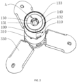
- the side surface of the first component is correspondingly provided with multiple cut planes, where two cut planes are set in parallel as a group.
- a support assembly which includes a support rod connected to the first component, and the support rod is provided with a bracket ring, which is surrounded by multiple support legs.
- the waterproof connector provided by this disclosure, when in use, allows the corresponding conductive strips to abut and connect by simply docking the first component with the second component, thereby making the entire circuit connected, which is convenient to operate.
- the drainage assembly set on the first component can timely discharge the accumulated water when water enters the connection point between the first and second components and is about to submerge the corresponding conductive strips, avoiding short circuits between adjacent conductive strips. This prevents damage to the electrical circuit or power supply due to short circuits during use, reducing safety hazards.
- first,” “second,” etc. are used for descriptive purposes only and should not be construed as indicating or implying relative importance or implicitly indicating the quantity of the indicated technical features.
- features defined with “first,” “second,” and other similar terms can explicitly or implicitly include one or more of such features.
- the meaning of “multiple” is two or more, unless otherwise specifically defined.
- the embodiment of this disclosure provides a waterproof connector, mainly used for outdoor electrical connections.
- the waterproof connector includes a first component 100, a second component 200, and a drainage assembly.
- the first component 100 is provided with a first conductive strip 140.
- the second component 200 is docked and connected with the first component 100, and the second component 200 is provided with a second conductive strip 230 that abuts the first conductive strip 140.
- the drainage assembly (not shown in the figure) is arranged on the first component 100 and corresponds to the position of the first conductive strip 140.
- FIGS. 2 and 4 there are multiple sets of the first conductive strip 140 and the second conductive strip 230.
- the waterproof connector provided in the embodiment of this disclosure, by installing the first conductive strip 140 and the second conductive strip 230 that need to be connected on the first component 100 and the second component 200 respectively, and then by docking the first component 100 with the second component 200, the first conductive strip 140 and the second conductive strip 230 can be abutted and connected, thus completing the conduction of the circuit.
- a drainage assembly is arranged on the first component 100 corresponding to the position of the first conductive strip 140, that is, a drainage assembly is arranged at the position where the first conductive strip 140 and the second conductive strip 230 are connected.
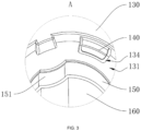
- the drainage assembly includes a drainage tray 130, which is installed on the end face of the first component 100 near the second component 200.
- the drainage tray 130 is provided with drainage holes 134, and the first conductive strip 140 is installed on the first component 100 and passes through the drainage holes 134.
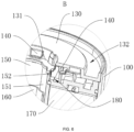
- the end face of the first component 100 near the second component 200 is provided with a water channel 180 that communicates with the drainage holes 134.
- the water channel 180 and the drainage tray 130 define a drainage cavity.
- the side wall of the water channel 180 is provided with a water leakage port 152, which communicates with the drainage cavity.
- the first conductive strip 140 passes through the drainage cavity and does not contact its inner side wall and bottom wall.
- This arrangement allows rainwater entering the connection surface between the first component 100 and the second component 200 to quickly enter the drainage cavity formed by the water channel 180 and the drainage tray 130, and then be discharged through the water leakage port 152.
- the first conductive strip 140 maintains a relative distance from the water flow, thereby reducing the probability of short circuits between adjacent conductive strips.
- the first conductive strip 140 and the second conductive strip 230 are both made of elastic metal strips, and the first conductive strip 140 is fixedly connected to the internal circuit of the first component 100, and the second conductive strip 230 is fixedly connected to the internal circuit of the second component 200.
- the good elasticity ensures a more reliable abutment connection between the first conductive strip 140 and the second conductive strip 230.
- the first conductive strip 140 and the second conductive strip 230 can be made of rigid metal strips.
- the drainage tray 130 near the end face of the second component 200 is provided with a docking groove 131, and the drainage hole 134 is set on the side wall of the docking groove 131 near the bottom of the groove.
- the drainage tray 130 is provided with a connection slot 132 near the end face of the second component 200
- the second component 200 is provided with a connecting ring 210 near the end face of the first component 100, corresponding to the connection slot 132.
- the connecting ring 210 is installed within the connection slot 132; the corresponding fit between the connecting ring 210 and the connection slot 132 facilitates accurate docking of the first component 100 with the second component 200, improving the docking installation efficiency of this embodiment.
- the docking faces of the first component 100 and the second component 200 can be set with square or circular protrusions and grooves to improve docking efficiency.
- connection slot 132 is provided with multiple first magnets 133 distributed towards the end face of the connecting ring 210, and the connecting ring 210 is provided with second magnets 211 corresponding to the first magnets 133.
- the first magnets 133 are magnetically connected to the second magnets 211, enhancing the docking installation efficiency of the first component 100 with the second component 200; where both the first magnets 133 and the second magnets 211 are chosen to be strong magnets to improve the connection reliability of the first component 100 with the second component 200.
- the first component 100 and the second component 200 can also be docked using other connection methods such as bolts or snaps.
- the first component 100 is provided with a connection through-hole 150 near the end face of the second component 200
- the second component 200 is provided with a connecting rod 240 near the end part of the first component 100.
- the connecting rod 240 is threaded through the connection through-hole 150; by threading the connecting rod 240 into the connection through-hole 150, the first component 100 can provide reliable radial support for the second component 200, facilitating the reliability of the connection between the first conductive strip 140 and the second conductive strip 230.
- connection through-hole 150 is provided with an arcuate protrusion 151
- side wall of the connecting rod 240 is provided with an arcuate groove 241.
- the arcuate protrusion 151 engages with the arcuate groove 241; this facilitates accurate docking of the first component 100 with the second component 200 and can effectively prevent incorrect or reversed connections between the first component 100 and the second component 200.
- a spacer tube 160 corresponding in shape can also be threaded through the connection through-hole 150.
- the spacer tube 160 can be chosen with different inner diameters to accommodate connecting rods 240 of different models of the second component 200, through the universality disclosed herein.
- the first component 100 is provided with a battery 170 inside, which is connected to the first conductive strip 140 via wires; the connection of the battery 170 through the first conductive strip 140 to the second conductive strip 230 can provide stable power to the exterior.
- the outside of the first component 100 is provided with a display screen 120 connected to the battery 170, which can display the remaining battery power.
- the second component 200 is provided with an illumination light 220, which is connected to the second conductive strip 230 via wires.
- the connection of the battery 170 through the first conductive strip 140 to the second conductive strip 230 can provide stable power to the illumination light 220, allowing it to provide stable illumination.
- the illumination light 220 is connected to the second component 200 via a lamp pole, with both ends of the lamp pole hingedly connected to the illumination light 220 and the second component 200, respectively. This facilitates the adjustment of the illumination direction of the illumination light 220, and the illumination light 220 is electrically connected to the second conductive strip 230 through the lamp pole and the wires set inside the second component 200.
- the second component 200 is provided with other electrical appliances, facilitating the combination by outdoor workers according to different needs, thereby enhancing the functionality of this disclosure.
- the second component 200 can also be provided with a second battery 170, and it can also dock with a third component, etc. By connecting multiple batteries 170 in series, the endurance of this disclosure can be improved.
- the side surface of the first component 100 is correspondingly provided with multiple cut planes 110, where two cut planes 110 are set in parallel as a pair, facilitating the storage stacking or transport clamping of the disclosure when not in use.
- the first component 100 is provided on the side away from the second component 200 with a support assembly, which includes a support rod 320.
- the support rod 320 is connected and installed with the first component 100, and the support rod 320 is provided with a bracket ring 310.
- the bracket ring 310 is provided on its peripheral side with multiple support legs 330, each of which is hingedly connected to the bracket ring 310, and the connections between each support leg 330 and the bracket ring 310 are set with the maximum spread angle, facilitating the stable support of the support assembly for this disclosure.
- the bracket ring 310 is sleeved on the support rod 320, and a locking component is provided between the bracket ring 310 and the support rod 320.
- the waterproof connector When using the waterproof connector provided by this disclosure, first place the first component 100 stably, then dock and install the second component 200 with the first component 100. During the process of the second component 200 gradually approaching and docking with the first component 100, the second conductive strip 230 on the second component 200 gradually approaches and finally contacts its corresponding first conductive strip 140, completing a stable connection. Especially when using this disclosure outdoors, it is easy to encounter rainy weather. During the rain, water can easily enter the docking gap between the first component 100 and the second component 200. The water entering the docking gap will first flow through the drainage hole 134 and enter the drainage cavity formed by the water channel 180 and the drainage tray 130, and finally be discharged from the water leakage port 152.
- the first conductive strip 140 is threaded through the drainage cavity and does not contact its inner side wall and bottom wall, it can further reduce the contact between the conductive strip and rainwater, lowering the risk of a short circuit in the conductive strip.
- the waterproof connector when in use, allows the corresponding conductive strips to be pressed against each other by docking the first component with the second component, thereby making the entire circuit connected, which is convenient to operate.
- the drainage component set on the first component can timely discharge the accumulated water when water enters the connection between the first and second components and is about to submerge the corresponding conductive strips, avoiding short circuits between adjacent conductive strips, thereby preventing damage to the electrical circuit or power supply due to short circuits during use, reducing safety hazards.
- the waterproof connector provided by this disclosure is reproducible and can be used in various industrial applications.
- the waterproof connector provided by this disclosure can be used in the field of electrical connectors.
Landscapes
- Engineering & Computer Science (AREA)
- General Engineering & Computer Science (AREA)
- Microelectronics & Electronic Packaging (AREA)
- Connector Housings Or Holding Contact Members (AREA)
Applications Claiming Priority (2)
| Application Number | Priority Date | Filing Date | Title |
|---|---|---|---|
| CN202322761483.4U CN221407752U (zh) | 2023-10-13 | 2023-10-13 | 防水连接器 |
| PCT/CN2023/127981 WO2025076872A1 (zh) | 2023-10-13 | 2023-10-30 | 防水连接器 |
Publications (2)
| Publication Number | Publication Date |
|---|---|
| EP4572031A1 true EP4572031A1 (de) | 2025-06-18 |
| EP4572031A4 EP4572031A4 (de) | 2025-06-18 |
Family
ID=95339704
Family Applications (1)
| Application Number | Title | Priority Date | Filing Date |
|---|---|---|---|
| EP23866654.9A Pending EP4572031A4 (de) | 2023-10-13 | 2023-10-30 | Wasserdichter steckverbinder |
Country Status (2)
| Country | Link |
|---|---|
| US (1) | US20250125555A1 (de) |
| EP (1) | EP4572031A4 (de) |
Family Cites Families (4)
| Publication number | Priority date | Publication date | Assignee | Title |
|---|---|---|---|---|
| CN210224415U (zh) * | 2019-08-05 | 2020-03-31 | 富士康(昆山)电脑接插件有限公司 | 防水电连接器 |
| CN213184752U (zh) * | 2020-09-23 | 2021-05-11 | 九阳股份有限公司 | 一种电连接器 |
| CN213278527U (zh) * | 2020-10-14 | 2021-05-25 | 浙江达威电子股份有限公司 | 防水的电连接器 |
| CN116171361A (zh) * | 2022-01-19 | 2023-05-26 | 深圳市栖息科技有限公司 | 照明装置 |
-
2023
- 2023-10-30 EP EP23866654.9A patent/EP4572031A4/de active Pending
-
2024
- 2024-04-28 US US18/648,452 patent/US20250125555A1/en active Pending
Also Published As
| Publication number | Publication date |
|---|---|
| JP3253228U (ja) | 2025-10-16 |
| US20250125555A1 (en) | 2025-04-17 |
| EP4572031A4 (de) | 2025-06-18 |
Similar Documents
| Publication | Publication Date | Title |
|---|---|---|
| US20250048574A1 (en) | Inverter, and, photovoltaic and energy storage system | |
| EP4572031A1 (de) | Wasserdichter steckverbinder | |
| WO2025076872A1 (zh) | 防水连接器 | |
| CN206833841U (zh) | 安装装置及采用该安装装置的显示屏单元 | |
| CN215170994U (zh) | 风扇 | |
| JP3253228U6 (ja) | 防水コネクタ | |
| CN213658931U (zh) | 蓄电池检测装置 | |
| CN212408426U (zh) | 一种吸顶式条形灯具 | |
| CN218887101U (zh) | 一种熔断器用绝缘外壳 | |
| CN220122265U (zh) | 一种光伏逆变器用接插件及光伏逆变器 | |
| CN207009001U (zh) | 控制单元及采用该控制单元的显示屏单元 | |
| CN218958104U (zh) | 防尘型电子连接器 | |
| CN219203584U (zh) | 一种电源插座 | |
| CN220272820U (zh) | 一种光伏连接器接头端子 | |
| CN215497085U (zh) | 天线滤波器装置 | |
| CN220672916U (zh) | 一种航空插头安装结构 | |
| CN218125063U (zh) | 便携式电子设备壳体及电子设备 | |
| CN218039591U (zh) | 一种定位端板、电池模组及电池包 | |
| CN218160957U (zh) | 一种便于安装的插排绝缘板 | |
| CN222826671U (zh) | 一种一体式连接器 | |
| CN217589609U (zh) | 易于装配的电动汽车充电口故障诊断连接器 | |
| CN220189793U (zh) | 电池包壳体、电池包、电池包组件及移动空调 | |
| CN216598135U (zh) | 一种琐式三插连接器内架 | |
| CN216055198U (zh) | 一种适用于自动化装配的异形接线端子连接结构 | |
| CN216214418U (zh) | 一种具有防护功能的电接插件 |
Legal Events
| Date | Code | Title | Description |
|---|---|---|---|
| STAA | Information on the status of an ep patent application or granted ep patent |
Free format text: STATUS: UNKNOWN |
|
| STAA | Information on the status of an ep patent application or granted ep patent |
Free format text: STATUS: THE INTERNATIONAL PUBLICATION HAS BEEN MADE |
|
| PUAI | Public reference made under article 153(3) epc to a published international application that has entered the european phase |
Free format text: ORIGINAL CODE: 0009012 |
|
| STAA | Information on the status of an ep patent application or granted ep patent |
Free format text: STATUS: REQUEST FOR EXAMINATION WAS MADE |
|
| STAA | Information on the status of an ep patent application or granted ep patent |
Free format text: STATUS: EXAMINATION IS IN PROGRESS |
|
| 17P | Request for examination filed |
Effective date: 20240328 |
|
| A4 | Supplementary search report drawn up and despatched |
Effective date: 20250416 |
|
| AK | Designated contracting states |
Kind code of ref document: A1 Designated state(s): AL AT BE BG CH CY CZ DE DK EE ES FI FR GB GR HR HU IE IS IT LI LT LU LV MC ME MK MT NL NO PL PT RO RS SE SI SK SM TR |
|
| 17Q | First examination report despatched |
Effective date: 20250526 |
|
| GRAP | Despatch of communication of intention to grant a patent |
Free format text: ORIGINAL CODE: EPIDOSNIGR1 |
|
| STAA | Information on the status of an ep patent application or granted ep patent |
Free format text: STATUS: GRANT OF PATENT IS INTENDED |
|
| RIC1 | Information provided on ipc code assigned before grant |
Ipc: H01R 13/52 20060101AFI20251001BHEP Ipc: H01R 13/62 20060101ALN20251001BHEP Ipc: H01R 24/68 20110101ALN20251001BHEP |
|
| DAV | Request for validation of the european patent (deleted) | ||
| DAX | Request for extension of the european patent (deleted) | ||
| INTG | Intention to grant announced |
Effective date: 20251014 |
|
| GRAS | Grant fee paid |
Free format text: ORIGINAL CODE: EPIDOSNIGR3 |
|
| GRAA | (expected) grant |
Free format text: ORIGINAL CODE: 0009210 |
|
| STAA | Information on the status of an ep patent application or granted ep patent |
Free format text: STATUS: THE PATENT HAS BEEN GRANTED |