EP4571173A1 - Planar illuminating device - Google Patents
Planar illuminating device Download PDFInfo
- Publication number
- EP4571173A1 EP4571173A1 EP23852279.1A EP23852279A EP4571173A1 EP 4571173 A1 EP4571173 A1 EP 4571173A1 EP 23852279 A EP23852279 A EP 23852279A EP 4571173 A1 EP4571173 A1 EP 4571173A1
- Authority
- EP
- European Patent Office
- Prior art keywords
- fresnel lens
- linear fresnel
- illumination device
- planar illumination
- area
- Prior art date
- Legal status (The legal status is an assumption and is not a legal conclusion. Google has not performed a legal analysis and makes no representation as to the accuracy of the status listed.)
- Pending
Links
Images


Classifications
-
- F—MECHANICAL ENGINEERING; LIGHTING; HEATING; WEAPONS; BLASTING
- F21—LIGHTING
- F21V—FUNCTIONAL FEATURES OR DETAILS OF LIGHTING DEVICES OR SYSTEMS THEREOF; STRUCTURAL COMBINATIONS OF LIGHTING DEVICES WITH OTHER ARTICLES, NOT OTHERWISE PROVIDED FOR
- F21V5/00—Refractors for light sources
- F21V5/007—Array of lenses or refractors for a cluster of light sources, e.g. for arrangement of multiple light sources in one plane
-
- F—MECHANICAL ENGINEERING; LIGHTING; HEATING; WEAPONS; BLASTING
- F21—LIGHTING
- F21V—FUNCTIONAL FEATURES OR DETAILS OF LIGHTING DEVICES OR SYSTEMS THEREOF; STRUCTURAL COMBINATIONS OF LIGHTING DEVICES WITH OTHER ARTICLES, NOT OTHERWISE PROVIDED FOR
- F21V13/00—Producing particular characteristics or distribution of the light emitted by means of a combination of elements specified in two or more of main groups F21V1/00 - F21V11/00
- F21V13/02—Combinations of only two kinds of elements
- F21V13/04—Combinations of only two kinds of elements the elements being reflectors and refractors
-
- F—MECHANICAL ENGINEERING; LIGHTING; HEATING; WEAPONS; BLASTING
- F21—LIGHTING
- F21V—FUNCTIONAL FEATURES OR DETAILS OF LIGHTING DEVICES OR SYSTEMS THEREOF; STRUCTURAL COMBINATIONS OF LIGHTING DEVICES WITH OTHER ARTICLES, NOT OTHERWISE PROVIDED FOR
- F21V5/00—Refractors for light sources
- F21V5/04—Refractors for light sources of lens shape
- F21V5/045—Refractors for light sources of lens shape the lens having discontinuous faces, e.g. Fresnel lenses
-
- F—MECHANICAL ENGINEERING; LIGHTING; HEATING; WEAPONS; BLASTING
- F21—LIGHTING
- F21V—FUNCTIONAL FEATURES OR DETAILS OF LIGHTING DEVICES OR SYSTEMS THEREOF; STRUCTURAL COMBINATIONS OF LIGHTING DEVICES WITH OTHER ARTICLES, NOT OTHERWISE PROVIDED FOR
- F21V7/00—Reflectors for light sources
- F21V7/0083—Array of reflectors for a cluster of light sources, e.g. arrangement of multiple light sources in one plane
-
- F—MECHANICAL ENGINEERING; LIGHTING; HEATING; WEAPONS; BLASTING
- F21—LIGHTING
- F21Y—INDEXING SCHEME ASSOCIATED WITH SUBCLASSES F21K, F21L, F21S and F21V, RELATING TO THE FORM OR THE KIND OF THE LIGHT SOURCES OR OF THE COLOUR OF THE LIGHT EMITTED
- F21Y2105/00—Planar light sources
- F21Y2105/10—Planar light sources comprising a two-dimensional [2D] array of point-like light-generating elements
- F21Y2105/14—Planar light sources comprising a two-dimensional [2D] array of point-like light-generating elements characterised by the overall shape of the two-dimensional [2D] array
-
- F—MECHANICAL ENGINEERING; LIGHTING; HEATING; WEAPONS; BLASTING
- F21—LIGHTING
- F21Y—INDEXING SCHEME ASSOCIATED WITH SUBCLASSES F21K, F21L, F21S and F21V, RELATING TO THE FORM OR THE KIND OF THE LIGHT SOURCES OR OF THE COLOUR OF THE LIGHT EMITTED
- F21Y2115/00—Light-generating elements of semiconductor light sources
- F21Y2115/10—Light-emitting diodes [LED]
Definitions
- the present invention relates to a planar illumination device.
- a direct-type planar illumination device having a linear Fresnel lens has been proposed (see Patent Document 1, or the like).
- the linear Fresnel lens By using the linear Fresnel lens, light distribution is efficiently performed, and high luminance, high luminance uniformity, low power consumption, and thinning, or the like are achieved.
- planar shape light-emitting surface shape
- a planar light source has been proposed with luminance unevenness occurring around the planar shape reduced (e.g., see Patent Document 2, or the like).
- light sources such as Light Emitting Diodes (LEDs) need to be linearly arranged along the light condensing position (focal point) of the linear Fresnel lens.
- LEDs Light Emitting Diodes
- linearly arranging the light sources becomes difficult along the light condensing position of the linear Fresnel lens up to the end part of the light emitting area due to the structural restriction of the frame edge part, degrading luminance uniformity due to the occurrence of dark area.
- the present invention has been made in view of the above, and an object of the present invention is to provide a planar illumination device capable of preventing the occurrence of a dark area in the irregular shape area and improving luminance uniformity.
- a planar illumination device is a direct-type planar illumination device having a linear Fresnel lens, and includes a plurality of light sources and a reflector.
- the plurality of light sources are linearly arranged on a substrate along a light condensing position of the linear Fresnel lens.
- the reflector having a plurality of reflective surfaces forming respective segments, each segment surrounding a corresponding one of the plurality of light sources.
- a segment of the reflector adjacent to the area is extended toward an outer edge side of the planar illumination device.
- the planar illumination device can prevent a dark area from occurring at the irregular shape area and can improve the luminance uniformity.
- a planar illumination device according to an embodiment will be described below with reference to the drawings.
- the present invention is not limited by this embodiment.
- the relationship between the dimensions of each element and the ratio of each element may differ from reality. Even between the drawings, there may be portions having the relationships and ratios of the dimensions different from each other.
- the contents described in one embodiment or modification are similarly applied to other embodiments or modifications.
- FIG. 1 is an external perspective view of a planar illumination device 1 according to an embodiment.
- the longitudinal direction of the planar illumination device 1 is an X-axis direction
- the lateral direction is a Y-axis direction
- the thickness direction is a Z-axis direction.
- the orientation during use is random.
- the planar illumination device 1 has a substantially rectangular (or substantially square) and plate-like outer shape.
- a housing is composed of a bottom frame (hidden behind the drawing) in the shape of a box with a floor for accommodating substrates or the like described later, and a top frame 9 covering the opening side of the bottom frame.
- An exit surface 1a (light emitting area) is formed at the top frame 9 by a substantially rectangular opening 9a, and light is emitted from the inside of the planar illumination device 1 toward the outside.
- an optical sheet 8 inside is exposed to the exit surface 1a. Details of the shape (irregular shape) of the opening 9a (exit surface 1a) will be described below.
- planar illumination device 1 When the planar illumination device 1 is used as a backlight for a vehicle-mounted display such as a cluster meter, a Center Information Display (CID), a head-up display and an indicator, a liquid crystal display device or the like is mounted at the exit surface 1a side.
- a vehicle-mounted display such as a cluster meter, a Center Information Display (CID), a head-up display and an indicator, a liquid crystal display device or the like is mounted at the exit surface 1a side.
- a vehicle-mounted display such as a cluster meter, a Center Information Display (CID), a head-up display and an indicator, a liquid crystal display device or the like is mounted at the exit surface 1a side.
- CID Center Information Display
- FIG. 2 is an exploded perspective view of the main part of the planar illumination device 1, and is viewed from the exit surface side as in FIG. 1 .
- the planar illumination device 1 consists of a substrate 3, a plurality of (many) light sources 4 being arranged at the substrate 3; a reflector 5; a condenser lens 6; a light distribution and field-of-view adjustment lens 7; and the optical sheet 8 attached to a bottom frame 2, and the top frame 9 fitting outside the bottom frame 2 to cover the bottom frame 2.
- the bottom frame 2 has a bottom part and four-sided sidewalls provided at the outer periphery of the bottom part.
- the bottom frame 2 is formed by die casting, sheet metal, or the like.
- the substrate 3 is fixed inside the bottom part of the bottom frame 2 through a fixing member (not illustrated) such as a double-sided tape.
- a fixing member such as a double-sided tape.
- light sources 4 composed of a plurality of (many) Light Emitting Diodes (LEDs) or the like, are arranged in a grid pattern.
- the plurality of light sources 4 can be driven by local dimming and are electrically connected so as to be individually lit.
- the luminance uniformity is further improved by adjusting the emission intensity of each light source 4.
- the back surface of the reflector 5 is fixed between the light sources 4 on the substrate 3 via a fixing member (not illustrated) composed of a plurality of double-sided strips or the like extending in the left-right direction (or the vertical direction) of the drawing.
- the reflector 5 has reflective surfaces surrounding each light source 4, and reflects light emitted at a wide angle from the light source 4 to the exit surface side to enhance the luminance.
- the reflector 5 is manufactured by injection molding of synthetic resin or the like.
- the condenser lens 6 disposed at the exit side of the reflector 5 condenses light incident from the light source 4 side into substantially parallel light.
- a linear Fresnel lens having uneven grooves extending in the longitudinal direction (X-axis direction) is provided at the exit surface, for example.
- the linear Fresnel lens may be provided at the incident surface of the condenser lens 6.
- the linear Fresnel lens has uneven grooves, corresponding to the inclined portion of the curved surface of a convex lens (cylindrical lens) and arranged in the short side direction (Y-axis direction).
- the linear Fresnel lens includes periodical portions in a number equal to the number of light sources 4 (arranged in the short side direction).
- the light distribution and field-of-view adjustment lens 7 includes a plurality of (many) minute prisms having uneven grooves extending in the X-axis direction, for example, at either the incident surface or the exit surface, and a plurality of (many) minute lenticular lenses having uneven grooves extending in the same direction. These prisms and lenticular lenses may be integrated as compound lenses.
- a plurality of (many) minute lenticular lenses having uneven grooves extending in the orthogonal Y-axis direction and adjusting the diffusion and luminance uniformity in the X-axis direction may be provided at the other surface.
- the optical sheet 8 disposed at the exit side of the light distribution and field-of-view adjustment lens 7 is a diffusion sheet or a polarization reflective sheet, but is not limited to this, and may be, for example, a prism sheet or a louver sheet.
- the diffusion sheet diffuses passing light.
- the polarization reflective sheet passes polarized light in a predetermined direction and reflects polarized light in a direction orthogonal to that predetermined direction.
- the top frame 9 is disposed at the exit surface side of the optical sheet 8, and the top frame 9 is fixed to the bottom frame 2.
- the top frame 9 is formed of resin, sheet metal, or the like.
- planar illumination device 1 is illustrated as a planar shape, the planar illumination device 1 may be curved.
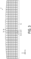
- FIG. 3 is a plan view of the reflector 5.
- the outside of the reflector 5 is surrounded by a sidewall 5a, and the inside of the reflector 5 is composed of respective segments for the corresponding light sources 4.
- Each segment has a substantially rectangular opening 5b, the light source 4 being exposed and arranged in the opening 5b, and a plurality of inclined reflective surfaces 5c, 5d, 5e, and 5f surrounding the opening 5b and opening toward the exit surface side.
- the reflector 5 has an irregular shape convex outward from a center part over substantially the entire length of the upper side.
- the reflective surface of the irregular shape area with the planar shape at the upper side being non-rectangular, is extended to the outer edge side as an extension section 5g.
- the extension section 5g is provided by tilting the reflective surfaces after making the opening of the irregular shape area the same shape as the opening 5b other than the irregular shape area. That is, the plurality of openings 5b exposing the light sources 4 of the reflector 5, are arranged in the same shapes and in a grid pattern, including the irregular shape area, and the reflective surface at the outer edge side of the irregular shape area is adjusted corresponding to the shape of the outer edge of the irregular shape area. In other words, in FIG.
- the ridge lines formed by the reflective surfaces 5d and 5f extend linearly in one direction (Y direction)
- the ridge lines formed by the reflective surfaces 5c and 5e extend linearly in a direction orthogonal to the one direction (X direction)
- only the ridge lines of the extension section 5g extend non-linearly (the valley line at the root is linear).
- the inclination angle of the reflective surface at the extension section 5g can be made constant over the entire length, and molding of the reflector 5 (manufacturing of a mold for molding the reflector 5) is further facilitated.
- This is also applicable to a case including, for example, an arc portion at a part of one side, or at a plurality of sides, of the outer edge of the rectangular opening, or a case including a straight line part not parallel to the grid, in addition to the opening 9a (exit surface 1a, light emitting area) shape of the present embodiment.
- the irregular shape area is not limited to a shape convex outward, but may also be concave inward. Further, instead of making the opening at the irregular shape area the same shape as the opening 5b at other than the irregular shape area, for example, the extension section 5g may be provided with a larger opening at the irregular shape area.
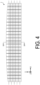
- FIG. 4 is a diagram simply illustrating the light emitting area of the planar illumination device 1 and the light condensing position with the light source arranged.
- the outline indicated by a broken line indicates the light emitting area.
- a center part of the upper side is irregular convex outward.
- a plurality of dashed lines extending in the horizontal direction (X-axis direction) of the drawing are the light condensing position (focal position) of a linear Fresnel lens 6a, and the light sources 4 are arranged at this light condensing position.
- the light condensing position and the positions of the light sources 4 may be parallel to each other with some distance apart.
- the light exiting from the linear Fresnel lens 6a can be inclined in the direction of arrangement of the prisms of the linear Fresnel lens 6a with respect to the optical axis of the light sources 4.
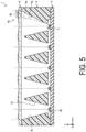
- FIG. 5 is a cross-sectional view of the planar illumination device 1 corresponding to the X-X section of FIG. 4 , and the bottom frame 2, the light distribution and field-of-view adjustment lens 7, the optical sheet 8, and the top frame 9 are not illustrated.
- the positions of the reflective surfaces 5c and 5e of the reflector 5 with respect to each light source 4 are almost the same in each segment, but in the irregular shape area at the right side, a removed section 5h is removed from the outer reflective surface to become the extension section 5g.
- the linear Fresnel lens 6a of the condenser lens 6 located at the exit surface side of the extension section 5g is an extension section 6b with the prism extending outward and continuing, unlike other areas.
- the condensing function is maintained even at the end part of the light emitting area, and luminance uniformity is further improved.
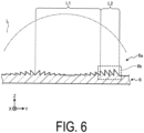
- FIG. 6 is an enlarged view of the extension section 6b of the condenser lens 6, and the extension section 6b of the prism is extended corresponding to a convex lens curved surface L of the cylindrical lens corresponding to the linear Fresnel lens 6a. That is, the other area in the segment corresponds to a partial curved surface L1 of the convex lens curved surface L, while the extension section 6b corresponds to a partial curved surface L2 continuing to the partial curved surface L1.
- the condensing by the linear Fresnel lens 6a is continuous even at the irregular shape area, and the occurrence of unevenness is prevented, and luminance uniformity is further improved.
- FIG. 7 is a diagram illustrating an example with a dark area DA occurring in a planar illumination device 1' of a comparative example due to the planar shape irregular and non-rectangular.
- the region surrounded by a broken line is a light emitting area of the planar illumination device 1', and the upper portion in the diagram has a planar shape irregular and non-rectangular.
- Each of the small squares indicates a segment, and in FIG. 7 , an area occurs projecting due to an irregular shape from the upper side of the segments arranged laterally at the upper side.
- the light sources are difficult to arrange linearly along the light condensing position of the linear Fresnel lens due to the structural restriction of the frame edge part (even when a linear Fresnel lens can be provided).
- each segment is surrounded by the reflective surfaces on four sides, light is not supplied to the upper irregular shape area and the dark area DA occurs, thereby lowering the luminance uniformity.
- FIG. 8 is a diagram illustrating another example with the dark area DA occurring in the planar illumination device 1' of a comparative example due to the planar shape irregular and non-rectangular.
- the irregular shape area is included in the sequence of segments.
- the light sources are difficult to arrange along the light condensing position of the linear Fresnel lens due to the structural restriction of the frame edge part, so that the dark area DA occurs.
- FIG. 9 is a diagram illustrating an example of the light condensing position with the light emitting area and the light sources arranged in the planar illumination device 1' of the comparative example, and corresponds to the arrangement of the light emitting area and the segments in FIG. 7 .
- a plurality of dashed lines extending in the horizontal direction (X-axis direction) are the light condensing position (focal position) of linear Fresnel lens 6a', and light sources 4' are arranged at the light condensing position.
- FIG. 10 is a cross-sectional view of the planar illumination device 1' corresponding to the X-X section of FIG. 9 , and the bottom frame, the light distribution and field-of-view adjustment lens, the optical sheet, and the top frame are not illustrated.
- a plurality of light sources 4' are arranged on a substrate 3', and a reflector 5' is arranged at the exit side of the light sources.
- Each light source 4' is exposed from the opening 5b', and reflective surfaces 5c' and 5e' are arranged at both sides of the opening 5b'.
- the removed section 5h is removed from the outer reflective surface in the irregular shape area at the right side, generating the extension section 5g. That is, at an area not enabling arrangement of (due to a lack of space or a small space) the light sources 4 at the light condensing position (of a virtually provided linear Fresnel lens) due to a planar shape of the light emitting area being irregular and non-rectangular in the planar illumination device 1, the segment of the reflector 5 adjacent to the area is extended toward the outer edge side of the planar illumination device 1.
- the light from the light source 4 reaches the end part of the light emitting area, so that the generation of a dark area at the irregular shape area is prevented and luminance uniformity is improved.
- the extension section 6b of the prism is provided at the linear Fresnel lens 6a corresponding to the portion of the extension section 5g extended by the removed section 5h of the reflector 5, the light-condensing function is also maintained, and the luminance uniformity of the portion supposed to be the dark area, is further improved. Furthermore, since the extension section 6b of the prism is continuously provided in accordance with the curved surface of the cylindrical lens corresponding to the linear Fresnel lens 6a, the occurrence of unevenness is prevented, and the luminance uniformity is further improved.
- the extending of the segment toward the outer edge side and the extending of the prism of the linear Fresnel lens 6a are performed in a direction orthogonal to the direction of extension of the uneven grooves of the linear Fresnel lens 6a. This enables simultaneous realization of the effect of extending the segment and the effect of extending the prism of the linear Fresnel lens 6a.
- linear Fresnel lens may be provided having uneven grooves extending in a direction orthogonal to the direction of the uneven grooves of the linear Fresnel lens 6a extending. This allows for a variety of light distributions.
- the other linear Fresnel lens is formed at a surface of the linear Fresnel lens, the surface being at an opposite side of the linear Fresnel lens 6a, or is formed separately from the linear Fresnel lens 6a. This increases the degree of freedom in the configuration of both linear Fresnel lenses.
- planar illumination device is a direct-type planar illumination device having a linear Fresnel lens, and includes:
- the segment of the reflector adjacent to the area is extended toward the outer edge side of the planar illumination device. This prevents generation of a dark area in the irregular shape area and improves luminance uniformity.
- a prism of the linear Fresnel lens is extended. This maintains the light-condensing function of the linear Fresnel lens, and further improves the luminance uniformity of the area having been supposed to become the dark area.
- the prism of the linear Fresnel lens is extended corresponding to a curved surface of a cylindrical lens corresponding to the linear Fresnel lens. This causes the condensing by the linear Fresnel lens to be continuous even at the irregular shape area, prevents the occurrence of unevenness, and further improves the luminance uniformity.
- the extending of the segment toward the outer edge side and the extending of the prism of the linear Fresnel lens are performed in a direction orthogonal to the direction of extension of the uneven grooves of the linear Fresnel lens extending. This enables to achieve simultaneously the effect of extending the segment and the effect of extending the prism of the linear Fresnel lens.
- linear Fresnel lens having uneven grooves extending in a direction orthogonal to the direction of the uneven grooves of the linear Fresnel lens extending. This allows for a variety of light distributions.
- the other linear Fresnel lens is formed at a surface of the linear Fresnel lens, the surface being at an opposite side of the linear Fresnel lens, or is formed separately from the linear Fresnel lens. This increases the degree of freedom in the configuration of both linear Fresnel lenses.
- the reflector has a plurality of openings exposing the light sources, the plurality of openings are arranged in the same shape and in a grid pattern, at the area including the irregular shape area, and the reflective surface at the outer edge side of the irregular shape area is adjusted corresponding to the shape of the outer edge of the irregular shape area. This facilitates manufacturing of mold for the reflector (mold for molding the reflector).
- a direct-type planar illumination device having a linear Fresnel lens includes:
- a prism of the linear Fresnel lens is extended. This prevents generation of a dark area in the irregular shape area and improves luminance uniformity.
- the present invention is not limited by the above embodiments.
- the present invention also includes configurations combining the above-described components appropriately. Further effects and modifications can be easily derived by those skilled in the art. Thus, a broader aspect of the present invention is not limited to the above-described embodiments, and various modifications can be made.
- 1 Planar illumination device 1a Exit surface, 2 Bottom frame, 3 Substrate, 4 Light source, 5 Reflector, 5a Sidewall, 5b Opening, 5c to 5f Reflective surface, 5g Extension section, 5h Removed section, 6 Condenser lens, 6a Linear Fresnel lens, 6b Extension section, 7 Light distribution and field-of-view adjustment lens, 8 Optical sheet, 9 Top frame, 9a Opening
Landscapes
- Engineering & Computer Science (AREA)
- General Engineering & Computer Science (AREA)
- Planar Illumination Modules (AREA)
Applications Claiming Priority (2)
| Application Number | Priority Date | Filing Date | Title |
|---|---|---|---|
| JP2022127388 | 2022-08-09 | ||
| PCT/JP2023/025062 WO2024034296A1 (ja) | 2022-08-09 | 2023-07-06 | 面状照明装置 |
Publications (1)
| Publication Number | Publication Date |
|---|---|
| EP4571173A1 true EP4571173A1 (en) | 2025-06-18 |
Family
ID=89851367
Family Applications (1)
| Application Number | Title | Priority Date | Filing Date |
|---|---|---|---|
| EP23852279.1A Pending EP4571173A1 (en) | 2022-08-09 | 2023-07-06 | Planar illuminating device |
Country Status (5)
| Country | Link |
|---|---|
| US (1) | US20260049708A1 (https=) |
| EP (1) | EP4571173A1 (https=) |
| JP (2) | JP7588737B2 (https=) |
| CN (1) | CN119677989A (https=) |
| WO (1) | WO2024034296A1 (https=) |
Families Citing this family (1)
| Publication number | Priority date | Publication date | Assignee | Title |
|---|---|---|---|---|
| WO2025178118A1 (ja) * | 2024-02-22 | 2025-08-28 | ミネベアミツミ株式会社 | 面状照明装置 |
Family Cites Families (10)
| Publication number | Priority date | Publication date | Assignee | Title |
|---|---|---|---|---|
| JP4873683B2 (ja) | 2005-04-19 | 2012-02-08 | チェイル インダストリーズ インコーポレイテッド | 面光源装置 |
| JP5322630B2 (ja) * | 2008-12-25 | 2013-10-23 | チェイル インダストリーズ インコーポレイテッド | 照明装置 |
| JP5467280B2 (ja) | 2009-05-25 | 2014-04-09 | 株式会社オプトデザイン | 照明装置 |
| JP2011151218A (ja) * | 2010-01-22 | 2011-08-04 | Stanley Electric Co Ltd | 発光装置 |
| JP6349106B2 (ja) * | 2014-03-03 | 2018-06-27 | 株式会社アイテックシステム | 照明装置 |
| CN208764682U (zh) * | 2018-10-31 | 2019-04-19 | 欧普照明股份有限公司 | 配光元件、光源组件及照明灯具 |
| JP6777253B2 (ja) * | 2019-03-08 | 2020-10-28 | 日亜化学工業株式会社 | 光源装置 |
| JP7307009B2 (ja) * | 2020-02-26 | 2023-07-11 | ミネベアミツミ株式会社 | 面状照明装置 |
| JP7560730B2 (ja) | 2020-05-29 | 2024-10-03 | 日亜化学工業株式会社 | 面状光源、液晶表示装置 |
| EP4177513B1 (en) | 2020-07-01 | 2026-04-22 | Minebea Mitsumi Inc. | Planar illumination device |
-
2023
- 2023-07-06 EP EP23852279.1A patent/EP4571173A1/en active Pending
- 2023-07-06 US US19/101,954 patent/US20260049708A1/en active Pending
- 2023-07-06 CN CN202380058535.1A patent/CN119677989A/zh active Pending
- 2023-07-06 WO PCT/JP2023/025062 patent/WO2024034296A1/ja not_active Ceased
- 2023-07-06 JP JP2023570459A patent/JP7588737B2/ja active Active
-
2024
- 2024-07-30 JP JP2024123776A patent/JP7546185B1/ja active Active
Also Published As
| Publication number | Publication date |
|---|---|
| JP7546185B1 (ja) | 2024-09-05 |
| US20260049708A1 (en) | 2026-02-19 |
| WO2024034296A1 (ja) | 2024-02-15 |
| JPWO2024034296A1 (https=) | 2024-02-15 |
| JP2024147823A (ja) | 2024-10-16 |
| JP7588737B2 (ja) | 2024-11-22 |
| CN119677989A (zh) | 2025-03-21 |
Similar Documents
| Publication | Publication Date | Title |
|---|---|---|
| US6425673B1 (en) | Light guide pipe having elongate roughened protrusions and/or roughened concaves, planar light source unit having a broad viewing angle characteristic, and liquid crystal display device | |
| JP5139310B2 (ja) | 面発光光源を用いるバックライト | |
| JP2020013714A (ja) | 面状照明装置 | |
| US11761608B2 (en) | Planar illumination device | |
| EP4571173A1 (en) | Planar illuminating device | |
| KR20200000330A (ko) | 면상 조명 장치 | |
| CN112601911A (zh) | 面状照明装置 | |
| JP2007227095A (ja) | 光混合部材、面光源装置 | |
| JP7670780B2 (ja) | 面状照明装置 | |
| US12595893B2 (en) | Planar illumination device | |
| JP6785397B2 (ja) | 面状照明装置 | |
| US12504659B2 (en) | Planar illumination device with local dimming | |
| JP6751452B2 (ja) | 面状照明装置 | |
| CN118696200A (zh) | 光学部件、光源装置以及平视显示器 | |
| JP7763996B2 (ja) | 面状照明装置 | |
| JP3981836B2 (ja) | 液晶表示パネルの照明装置 | |
| US20250359402A1 (en) | Light emitting device, surface light source device, and display device | |
| WO2022244350A1 (ja) | 面状照明装置 | |
| KR20200124368A (ko) | 도광체 및 이를 구비하는 백라이트 장치 | |
| JP2018045900A (ja) | 面光源装置および表示装置 |
Legal Events
| Date | Code | Title | Description |
|---|---|---|---|
| STAA | Information on the status of an ep patent application or granted ep patent |
Free format text: STATUS: THE INTERNATIONAL PUBLICATION HAS BEEN MADE |
|
| PUAI | Public reference made under article 153(3) epc to a published international application that has entered the european phase |
Free format text: ORIGINAL CODE: 0009012 |
|
| STAA | Information on the status of an ep patent application or granted ep patent |
Free format text: STATUS: REQUEST FOR EXAMINATION WAS MADE |
|
| 17P | Request for examination filed |
Effective date: 20250203 |
|
| AK | Designated contracting states |
Kind code of ref document: A1 Designated state(s): AL AT BE BG CH CY CZ DE DK EE ES FI FR GB GR HR HU IE IS IT LI LT LU LV MC ME MK MT NL NO PL PT RO RS SE SI SK SM TR |
|
| DAV | Request for validation of the european patent (deleted) | ||
| DAX | Request for extension of the european patent (deleted) | ||
| P01 | Opt-out of the competence of the unified patent court (upc) registered |
Free format text: CASE NUMBER: UPC_APP_0003838_4571173/2026 Effective date: 20260203 |