EP4568290A1 - Verfahren und vorrichtung zur konfiguration eines audiosystems - Google Patents
Verfahren und vorrichtung zur konfiguration eines audiosystems Download PDFInfo
- Publication number
- EP4568290A1 EP4568290A1 EP24213498.9A EP24213498A EP4568290A1 EP 4568290 A1 EP4568290 A1 EP 4568290A1 EP 24213498 A EP24213498 A EP 24213498A EP 4568290 A1 EP4568290 A1 EP 4568290A1
- Authority
- EP
- European Patent Office
- Prior art keywords
- video
- audio
- displayed
- listening
- listening area
- Prior art date
- Legal status (The legal status is an assumption and is not a legal conclusion. Google has not performed a legal analysis and makes no representation as to the accuracy of the status listed.)
- Pending
Links
Images



Classifications
-
- H—ELECTRICITY
- H04—ELECTRIC COMMUNICATION TECHNIQUE
- H04S—STEREOPHONIC SYSTEMS
- H04S7/00—Indicating arrangements; Control arrangements, e.g. balance control
- H04S7/30—Control circuits for electronic adaptation of the sound field
- H04S7/302—Electronic adaptation of stereophonic sound system to listener position or orientation
-
- H—ELECTRICITY
- H04—ELECTRIC COMMUNICATION TECHNIQUE
- H04S—STEREOPHONIC SYSTEMS
- H04S7/00—Indicating arrangements; Control arrangements, e.g. balance control
- H04S7/30—Control circuits for electronic adaptation of the sound field
- H04S7/302—Electronic adaptation of stereophonic sound system to listener position or orientation
- H04S7/303—Tracking of listener position or orientation
-
- H—ELECTRICITY
- H04—ELECTRIC COMMUNICATION TECHNIQUE
- H04S—STEREOPHONIC SYSTEMS
- H04S7/00—Indicating arrangements; Control arrangements, e.g. balance control
- H04S7/40—Visual indication of stereophonic sound image
-
- H—ELECTRICITY
- H04—ELECTRIC COMMUNICATION TECHNIQUE
- H04S—STEREOPHONIC SYSTEMS
- H04S2400/00—Details of stereophonic systems covered by H04S but not provided for in its groups
- H04S2400/11—Positioning of individual sound objects, e.g. moving airplane, within a sound field
Definitions
- a method and device for configuring an audio system are described, using a camera to select a listening area.
- the method and device can be used, in particular, for configuring a home audio system.
- An audio system for example a home audio system, can be associated with a listening zone, which represents a sound diffusion location in which a listener benefits from sound that meets desired criteria. Determining such a zone may require the implementation of various additional equipment. For example, it may be necessary to implement a microphone to make sound recordings in the room in which the audio system is placed, or to use a mobile phone. The recorded sound must then be processed by dedicated software to identify the listening zone. Other solutions may require in-depth knowledge of acoustics and sound reinforcement. The problem increases if several listening zones are envisaged, these listening zones corresponding for example to different configurations of the sound processing by the audio system. Switching from one zone to another requires carrying out the operations mentioned above again.
- the visual feedback obtained in real time using the camera helps the user with the configuration of the premises and/or the choice of a listening area and its geometric parameters.
- the video to be displayed may include only a part of the video obtained by the camera, in the sense that only a part of the camera's field of vision is reproduced in the video to be displayed.
- a listening zone is an area in which the sound produced by the audio source(s) meets one or more quality criteria.
- the method comprises superimposing, in the video to be displayed, a menu comprising several choices of value of a parameter, highlighting a current choice of parameter value, as well as the graphical representation of a listening zone corresponding only to a current choice of parameter value.
- the method comprises displaying an invitation to a user to move a piece of furniture in the broadcast location based on the graphical representation.
- a geometric parameter is defined by a value, or a range of values, or an open range.
- One or more exemplary embodiments relate to a device comprising a camera, at least one audio source, a processor and a memory comprising software code, the processor, when executing the software code, causing the device to implement one of the methods described.
- the at least one audio source can be oriented either manually or by means of an actuator.
- each block of a block diagram or each phase of a flowchart may represent a module or a portion of software code comprising instructions for implementing one or more functions. According to certain implementations, the order of the blocks or phases may be changed, or the corresponding functions may be implemented in parallel.
- the process blocks or phases may be implemented using circuits, software or a combination of circuits and software, in a centralized manner, or in a distributed manner, for all or part of the blocks or phases.
- a suitable data processing system or device comprises, for example, a combination of software code and circuits, such as a processor, controller or other circuit suitable for executing the software code.
- the processor or controller causes the system or device to implement all or part of the functionalities of the blocks and/or phases of the methods or processes according to the exemplary embodiments.
- the software code may be stored in non-volatile memory or a readable non-volatile storage medium (USB key, memory card or other medium) directly or through an interface suitable for the processor or controller.
- FIG. 1 is a schematic diagram of an audio system illustrating one or more embodiments in a non-limiting manner.
- the system of the Figure 1 comprises a configuration device 100 and a screen 101.
- the device 100 can be controlled by a user 102 using a remote control 103.
- the device 100 comprises a camera 104, a processor 105, a non-volatile memory 106 comprising software code, and an audio processing processor 107.
- the various components of the device 100 are connected by an internal bus 110.
- the audio processing processor 107 receives audio data as input and generates audio signals intended to be reproduced by one or more audio sources, represented here by two loudspeakers 108 and 109.
- the device 100 further comprises an interface (not illustrated) by which it is connected to the screen 101. This interface is for example an HDMI interface.
- the device 100 is adapted to generate a video signal for display on the screen 101.
- the generation of the video signal is for example carried out by the processor 104.
- the system of the Figure 1 is given for illustrative purposes for the clarity of presentation of the exemplary embodiments and a current implementation may obviously differ.
- the device 100 may comprise a single speaker or more than two speakers.
- the speakers 108 and 109 are fixed or orientable.
- the orientation may be adjusted manually or via actuators such as electric motors.
- position sensors are associated with the manually orientable speakers to allow the device 100 to determine the orientation.
- the device 100 integrates for example a video receiver and decoder functionality in addition to the audio and camera functionalities (product designated under the name 'video and sound box' or 'video sound box' in English). It should also be noted that both the functionality of the processor 105 and that of the processor 107 can be implemented with more than one component, or even be jointly implemented by one or more components. For example, a single processor can be used to implement both functionalities.
- the device 100 comprises two audio sources and the camera is placed on an axis of symmetry 111 of these audio sources. This is however not obligatory.
- FIG. 2 a schematic diagram illustrating an example of system placement Figure 1 in a room 200.
- the camera 104 of the device 100 has a horizontal viewing angle AdV_H.
- the room also includes furniture such as a sofa 202.
- a listening zone 201 is schematically represented by an ellipse, but its actual shape depends on the implementation, the number of loudspeakers, etc.
- a listening zone is a sound diffusion zone in which a listener benefits from sound meeting desired criteria, for example quality criteria. Such a criterion is, for example, that the phase shift between the sounds produced by the different loudspeakers is below a certain threshold, so that the stereophonic or spatial perception is of a desired level of quality.
- the geometric parameters defining a listening zone include, for example, the distance of a listening zone from the audio sources, or the width of the zone.
- the audio processing receives at least these geometric parameters as input and generates corresponding audio signals.
- a graphical representation of a listening area is displayed on the screen, superimposed with a video image obtained by the camera 104 of the room in which the device 100 is located.
- This visual feedback helps the user in real time with the configuration of the premises and/or the choice of a listening area.
- This choice may for example include the selection of a listening area from a list, the selection of one or more parameters defining a listening area or any other action or series of actions resulting in a determination of a listening area by the user.
- the configuration of the premises includes for example the movement of furniture so that a listener can easily position themselves in the listening area. In the specific context of the example of the Figure 2 , this can be achieved by placing for example the sofa 201 in the listening area.
- the choice of a listening area makes it possible to obtain a new listening area, for example more or less wide or more or less distant from the device 100.
- This choice of a new listening area is followed by a configuration of the audio processing carried out by the device 100 so that the characteristics of the sound produced correspond to the new listening area.
- the display is updated on the fly according to the user's choice.
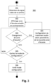
- FIG. 3 is a flowchart of a configuration method 300 according to one or more exemplary embodiments.
- a signal representative of the video of the room in which the audio system is broadcasting is obtained from the camera.
- a graphical representation of the currently configured listening area is added as an overlay on this video.
- a corresponding video signal is generated for display on the screen 101.
- the user 102 may then decide to change the listening area.
- Various ways of making this choice may then be envisaged, some of which are illustrated in the figures 5 to 10 described further.
- the audio processing is adapted to the new listening area and the new listening area is displayed as an overlay at 302, which allows the user to both appreciate the new sound processing and visualize the new listening area.
- the user is offered the option of selecting a listening area for overlay display, but only actually configuring the audio processing following additional validation of a selected listening area.
- This alternative allows the user to view a listening area (or several listening areas consecutively) without modifying the audio processing configuration parameters.
- the user decides not to - or no longer to - change the current listening zone in 303, he is asked to exit the configuration mode in 305. If this is the case, the configuration mode is stopped in 306. If not, the process loops back to 303.
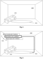
- FIG. 4 is a schematic representation of a video image that can be displayed with, superimposed, a graphical representation of a listening area 401.
- THE figures 5 to 10 are schematic representations of video images illustrating the display on the screen at various stages of the process. Some of these figures illustrate in particular particular implementations for the configuration or the selection of a listening zone. Some implementations implement menus, it being noted that these implementations are given only as examples and that other ways of Configuring a listening zone can be implemented, in particular by explicitly entering parameter values for a desired listening zone.
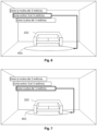
- FIG. 5 illustrates an initial positioning of the listening area visually delineated by the graphical representation 401, with a sofa 202 placed to the left of the room, outside the current listening area. The user can then either choose another listening area and/or move their sofa.
- the overlay video displayed on the screen provides immediate, real-time visual feedback helping the user to correctly move their furniture to a location in the room within the current listening area.
- the user can choose a listening area by configuring a distance between the device 100 and the listening area.
- Figure 5 illustrates a possible example of choices offered at 501, with a limited number of predefined choices presented on the screen as individually selectable menu items.
- three choices are displayed, namely a distance of less than three meters, a distance between 3 and 5 meters and a distance of more than 5 meters.
- the distance is defined here by a range, but it is quite possible to define a distance by a single value.
- the distance range indicates for example the distance frame for which the audio processing input parameters will not be modified as long as the user's distance remains within the frame.
- the intermediate distance is selected, the corresponding element is visually highlighted, and the corresponding graphical representation of the listening area is displayed superimposed on the video image.
- the user can either change the location of his furniture or vary the listening area.
- the user can, for example, align his sofa with the displayed listening area and/or indicate at what distance from the device he wishes to place the listening area.
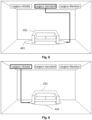
- the Figure 6 illustrates the alignment.
- the user chooses the distance corresponding to the location (the furthest distance in the example). This last case is illustrated by the Figure 7 .
- the user can also configure the width of the listening area.
- figure 8 illustrates an example of width choices, with a limited number of predefined choices presented on screen as individually selectable menu items.
- three choices are displayed, namely reduced width, standard width and extended width.
- the standard width has been selected and the corresponding element is visually highlighted in value.
- the figures 9 And 10 respectively represent the video image with the graphical representations of reduced width and extended width areas.
- the orientation of the sound source(s) may be modified.
- a listening area is associated with each orientation of the sound source(s), as well as a corresponding graphical representation.
- the device 100 then allows the user to preview the graphic representation of a listening zone for a particular orientation.
- a user first modifies the orientation of the sound sources, and the device 100 then generates a display, a graphical representation of the listening area corresponding to this orientation.
- the device determines the orientation of the sources either automatically using suitable sensors or based on information provided by the user.
- the use of sensors also makes it possible to verify that the orientations of several audio sources correspond to an authorized configuration and thus to warn the user accordingly.
- the user may have oriented two symmetrical sources with non-symmetrical orientations.
- the orientation of the audio source(s) is adjustable by one or more actuators.
- An actuator can be controlled by the processor 105 according to a command entered by the user. This command is for example a choice of a particular orientation.
- the adjustment of the orientation can be carried out as appropriate once the user is satisfied with a previewed listening area, or immediately according to a viewed listening area.
- the orientation of the audio sources is a configuration parameter for processing the audio data by the audio processor 107.
- FIG. 11 is a schematic diagram of a portion of the device 100 in the case where this device comprises two audio sources which, combined, generate stereo sound.
- the audio source can take three predefined orientations.
- the default orientation is for example an angle ⁇ of 45° relative to an axis parallel to the axis of symmetry of the device, with the other two positions varying for example by ⁇ ⁇ ° relative to the default position. Of course other positions can be chosen.
- the three possible orientations can be arbitrarily labeled, for example from 1 to 3, with orientation 2 being the default. This numbering may optionally be reported on the housing of the device 100 for easy identification of a current orientation of the audio source(s).
- the orientation can take more or less distinct values.
- the orientation of an audio source is continuously adjustable.
- FIG 12 is a schematic representation of a video image illustrating the display on the screen of three menu items having the orientations illustrated by the Figure 11
- a graphical representation of the listening area corresponding to the current orientation is displayed as an overlay. The corresponding element is visually highlighted.
- the figure 13 illustrates the case where the first orientation is selected, giving a wider listening area.
- FIG. 14 is a schematic diagram illustrating a method for determining the position of a point in the image as a function of a distance. This method can be applied to place a graphical representation at a given distance from the device 100.
- the diagram of the figure 14 represents a side view of the device 100 placed on a piece of furniture 1401 just in front of the screen 101.
- the camera of the device 100 has a vertical viewing angle AdV_V, in degrees. It is placed at a height h1 from the ground.
- the video return plane 1402 of the camera has a height h in number of pixels.
- the ground represented by the bottom L1 of this plane is located at a distance d1 from the camera.
- the camera can be inclined at an angle 'inc' relative to the horizontal.
- nbpx the number of pixels between the bottom of the camera's video return plane, i.e. line L1, and a line L2 of this plane, line L2 corresponding in plane 1402 to a line A in the room and for which we wish to determine the distance d2 from the camera.
- nbpx therefore represents a number of pixels on a vertical line in the image, between the two lines L1 and L2.
- ⁇ and ß represent respectively the angle between the horizontal and the straight line passing through the camera and line L2, and the angle between the horizontal and the straight line passing through the camera and L1.
- Line L2 is the projection of line A onto plane 1402 along the straight line passing through the camera and line A.
- FIG. 15 is a schematic diagram showing the placement of lines L1 and L2 in the displayed image. Lines L2 and A overlap in this image.
- an extended width ZE3 corresponds to 3 ⁇ 4 of the camera's viewing angle AdV_H
- a standard width ZE2 corresponds to 1/2 of this viewing angle
- a reduced width ZE1 corresponds to 1 ⁇ 4 of this viewing angle. If the horizontal resolution of the camera sensor is resH, then it is sufficient to apply a coefficient of 3 ⁇ 4, 1 ⁇ 2, or 1 ⁇ 4 to obtain the width in pixels of the listening area.
Landscapes
- Physics & Mathematics (AREA)
- Engineering & Computer Science (AREA)
- Acoustics & Sound (AREA)
- Signal Processing (AREA)
- User Interface Of Digital Computer (AREA)
- Stereophonic System (AREA)
Applications Claiming Priority (1)
| Application Number | Priority Date | Filing Date | Title |
|---|---|---|---|
| FR2313491A FR3156221A1 (fr) | 2023-12-04 | 2023-12-04 | Procédé et dispositif de configuration d’un système audio |
Publications (1)
| Publication Number | Publication Date |
|---|---|
| EP4568290A1 true EP4568290A1 (de) | 2025-06-11 |
Family
ID=89573390
Family Applications (1)
| Application Number | Title | Priority Date | Filing Date |
|---|---|---|---|
| EP24213498.9A Pending EP4568290A1 (de) | 2023-12-04 | 2024-11-18 | Verfahren und vorrichtung zur konfiguration eines audiosystems |
Country Status (3)
| Country | Link |
|---|---|
| US (1) | US20250184683A1 (de) |
| EP (1) | EP4568290A1 (de) |
| FR (1) | FR3156221A1 (de) |
Citations (7)
| Publication number | Priority date | Publication date | Assignee | Title |
|---|---|---|---|---|
| US20140096003A1 (en) * | 2012-09-28 | 2014-04-03 | Tesla Motors, Inc. | Vehicle Audio System Interface |
| US20150373452A1 (en) * | 2013-02-05 | 2015-12-24 | Toa Corporation | Loudspeaker System |
| US20170374465A1 (en) * | 2014-09-26 | 2017-12-28 | Apple Inc. | Audio system with configurable zones |
| US20180088900A1 (en) * | 2016-09-27 | 2018-03-29 | Grabango Co. | System and method for differentially locating and modifying audio sources |
| US20210266692A1 (en) * | 2018-06-25 | 2021-08-26 | Sony Corporation | Information processing device, information processing method, and information processing system |
| US20210385604A1 (en) * | 2020-06-05 | 2021-12-09 | Sony Corporation | Angular sensing for optimizing speaker listening experience |
| US20230239646A1 (en) * | 2016-08-31 | 2023-07-27 | Harman International Industries, Incorporated | Loudspeaker system and control |
-
2023
- 2023-12-04 FR FR2313491A patent/FR3156221A1/fr active Pending
-
2024
- 2024-11-18 EP EP24213498.9A patent/EP4568290A1/de active Pending
- 2024-12-03 US US18/967,597 patent/US20250184683A1/en active Pending
Patent Citations (7)
| Publication number | Priority date | Publication date | Assignee | Title |
|---|---|---|---|---|
| US20140096003A1 (en) * | 2012-09-28 | 2014-04-03 | Tesla Motors, Inc. | Vehicle Audio System Interface |
| US20150373452A1 (en) * | 2013-02-05 | 2015-12-24 | Toa Corporation | Loudspeaker System |
| US20170374465A1 (en) * | 2014-09-26 | 2017-12-28 | Apple Inc. | Audio system with configurable zones |
| US20230239646A1 (en) * | 2016-08-31 | 2023-07-27 | Harman International Industries, Incorporated | Loudspeaker system and control |
| US20180088900A1 (en) * | 2016-09-27 | 2018-03-29 | Grabango Co. | System and method for differentially locating and modifying audio sources |
| US20210266692A1 (en) * | 2018-06-25 | 2021-08-26 | Sony Corporation | Information processing device, information processing method, and information processing system |
| US20210385604A1 (en) * | 2020-06-05 | 2021-12-09 | Sony Corporation | Angular sensing for optimizing speaker listening experience |
Also Published As
| Publication number | Publication date |
|---|---|
| US20250184683A1 (en) | 2025-06-05 |
| FR3156221A1 (fr) | 2025-06-06 |
Similar Documents
| Publication | Publication Date | Title |
|---|---|---|
| FR2857810A1 (fr) | Appareil d'affichage video ayant une fonction de variation du rapport de visualisation et procede de commande de celui-ci | |
| EP1630811B1 (de) | System und Methode zur automatischen Erstellung von Gerät-abhängigem High-Definition Material | |
| CA2752691C (en) | Systems, apparatus and methods for subtitling for stereoscopic content | |
| JP5620651B2 (ja) | 再生装置、撮像装置、及びその制御方法 | |
| US8294711B2 (en) | Device, method, and program for three-dimensional imaging by reducing or eliminating parallax during a zoom operation | |
| JP5933931B2 (ja) | 設定メニューを表示する方法及び対応するデバイス | |
| FR2646307A1 (fr) | Systeme image dans l'image utilisant une synchronisation a la frequence verticale pour televiseur | |
| US10291907B2 (en) | Multi-view display control for channel selection | |
| WO2012011341A1 (ja) | 撮像装置、その制御方法およびプログラム | |
| CN102498499A (zh) | 提供用于显示的图像的方法和设备 | |
| FR2594241A1 (fr) | Processeur d'affichage de donnees sur un ecran d'affichage et procede d'affichage de donnees mettant en oeuvre ce dispositif | |
| US20200053395A1 (en) | Video distribution system, user terminal device, and video distribution method | |
| CN102196288A (zh) | 图像处理设备、图像转换方法和程序 | |
| US20150033123A1 (en) | Audio-visual interface for apparatus | |
| US8831383B2 (en) | Enhanced techniques for visual image alignment of a multi-layered document composition | |
| WO2017113720A1 (zh) | 一种视频播放方法及装置 | |
| WO2015038862A1 (en) | Depth key compositing for video and holographic projection | |
| KR102561371B1 (ko) | 디스플레이장치와, 기록매체 | |
| EP3460674A1 (de) | Vorrichtung, verfahren und programm zur anzeigen von fischaugenminiaturbildern | |
| US20140009663A1 (en) | Image capture device and audio hinting method thereof in focusing | |
| EP4568290A1 (de) | Verfahren und vorrichtung zur konfiguration eines audiosystems | |
| US20130016094A1 (en) | Vergence control method for stereo-scopic image control and portable device supporting the same | |
| WO2002045412A1 (fr) | Methode de visualisation d'un objet dans une fenetre d'un panorama | |
| JP2006086717A (ja) | 画像表示システム、画像再生装置及びレイアウト制御装置 | |
| US20130215225A1 (en) | Display apparatus and method for adjusting three-dimensional effects |
Legal Events
| Date | Code | Title | Description |
|---|---|---|---|
| PUAI | Public reference made under article 153(3) epc to a published international application that has entered the european phase |
Free format text: ORIGINAL CODE: 0009012 |
|
| STAA | Information on the status of an ep patent application or granted ep patent |
Free format text: STATUS: EXAMINATION IS IN PROGRESS |
|
| 17P | Request for examination filed |
Effective date: 20241118 |
|
| AK | Designated contracting states |
Kind code of ref document: A1 Designated state(s): AL AT BE BG CH CY CZ DE DK EE ES FI FR GB GR HR HU IE IS IT LI LT LU LV MC ME MK MT NL NO PL PT RO RS SE SI SK SM TR |
|
| GRAP | Despatch of communication of intention to grant a patent |
Free format text: ORIGINAL CODE: EPIDOSNIGR1 |
|
| STAA | Information on the status of an ep patent application or granted ep patent |
Free format text: STATUS: GRANT OF PATENT IS INTENDED |
|
| INTG | Intention to grant announced |
Effective date: 20260211 |