EP4568021A1 - Klemmeneinrichtung zum anschliessen eines elektrischen leiters - Google Patents
Klemmeneinrichtung zum anschliessen eines elektrischen leiters Download PDFInfo
- Publication number
- EP4568021A1 EP4568021A1 EP24217018.1A EP24217018A EP4568021A1 EP 4568021 A1 EP4568021 A1 EP 4568021A1 EP 24217018 A EP24217018 A EP 24217018A EP 4568021 A1 EP4568021 A1 EP 4568021A1
- Authority
- EP
- European Patent Office
- Prior art keywords
- clamping
- housing
- busbar
- contact
- terminal device
- Prior art date
- Legal status (The legal status is an assumption and is not a legal conclusion. Google has not performed a legal analysis and makes no representation as to the accuracy of the status listed.)
- Pending
Links
Images




Classifications
-
- H—ELECTRICITY
- H01—ELECTRIC ELEMENTS
- H01R—ELECTRICALLY-CONDUCTIVE CONNECTIONS; STRUCTURAL ASSOCIATIONS OF A PLURALITY OF MUTUALLY-INSULATED ELECTRICAL CONNECTING ELEMENTS; COUPLING DEVICES; CURRENT COLLECTORS
- H01R4/00—Electrically-conductive connections between two or more conductive members in direct contact, i.e. touching one another; Means for effecting or maintaining such contact; Electrically-conductive connections having two or more spaced connecting locations for conductors and using contact members penetrating insulation
- H01R4/28—Clamped connections, spring connections
- H01R4/48—Clamped connections, spring connections utilising a spring, clip, or other resilient member
- H01R4/4809—Clamped connections, spring connections utilising a spring, clip, or other resilient member using a leaf spring to bias the conductor toward the busbar
- H01R4/48185—Clamped connections, spring connections utilising a spring, clip, or other resilient member using a leaf spring to bias the conductor toward the busbar adapted for axial insertion of a wire end
- H01R4/4819—Clamped connections, spring connections utilising a spring, clip, or other resilient member using a leaf spring to bias the conductor toward the busbar adapted for axial insertion of a wire end the spring shape allowing insertion of the conductor end when the spring is unbiased
- H01R4/4821—Single-blade spring
-
- H—ELECTRICITY
- H01—ELECTRIC ELEMENTS
- H01R—ELECTRICALLY-CONDUCTIVE CONNECTIONS; STRUCTURAL ASSOCIATIONS OF A PLURALITY OF MUTUALLY-INSULATED ELECTRICAL CONNECTING ELEMENTS; COUPLING DEVICES; CURRENT COLLECTORS
- H01R13/00—Details of coupling devices of the kinds covered by groups H01R12/70 or H01R24/00 - H01R33/00
- H01R13/02—Contact members
-
- H—ELECTRICITY
- H01—ELECTRIC ELEMENTS
- H01R—ELECTRICALLY-CONDUCTIVE CONNECTIONS; STRUCTURAL ASSOCIATIONS OF A PLURALITY OF MUTUALLY-INSULATED ELECTRICAL CONNECTING ELEMENTS; COUPLING DEVICES; CURRENT COLLECTORS
- H01R11/00—Individual connecting elements providing two or more spaced connecting locations for conductive members which are, or may be, thereby interconnected, e.g. end pieces for wires or cables supported by the wire or cable and having means for facilitating electrical connection to some other wire, terminal, or conductive member, blocks of binding posts
- H01R11/01—Individual connecting elements providing two or more spaced connecting locations for conductive members which are, or may be, thereby interconnected, e.g. end pieces for wires or cables supported by the wire or cable and having means for facilitating electrical connection to some other wire, terminal, or conductive member, blocks of binding posts characterised by the form or arrangement of the conductive interconnection between the connecting locations
-
- H—ELECTRICITY
- H01—ELECTRIC ELEMENTS
- H01R—ELECTRICALLY-CONDUCTIVE CONNECTIONS; STRUCTURAL ASSOCIATIONS OF A PLURALITY OF MUTUALLY-INSULATED ELECTRICAL CONNECTING ELEMENTS; COUPLING DEVICES; CURRENT COLLECTORS
- H01R13/00—Details of coupling devices of the kinds covered by groups H01R12/70 or H01R24/00 - H01R33/00
- H01R13/02—Contact members
- H01R13/193—Means for increasing contact pressure at the end of engagement of coupling part, e.g. zero insertion force or no friction
-
- H—ELECTRICITY
- H01—ELECTRIC ELEMENTS
- H01R—ELECTRICALLY-CONDUCTIVE CONNECTIONS; STRUCTURAL ASSOCIATIONS OF A PLURALITY OF MUTUALLY-INSULATED ELECTRICAL CONNECTING ELEMENTS; COUPLING DEVICES; CURRENT COLLECTORS
- H01R13/00—Details of coupling devices of the kinds covered by groups H01R12/70 or H01R24/00 - H01R33/00
- H01R13/62—Means for facilitating engagement or disengagement of coupling parts or for holding them in engagement
- H01R13/639—Additional means for holding or locking coupling parts together, after engagement, e.g. separate keylock, retainer strap
-
- H—ELECTRICITY
- H01—ELECTRIC ELEMENTS
- H01R—ELECTRICALLY-CONDUCTIVE CONNECTIONS; STRUCTURAL ASSOCIATIONS OF A PLURALITY OF MUTUALLY-INSULATED ELECTRICAL CONNECTING ELEMENTS; COUPLING DEVICES; CURRENT COLLECTORS
- H01R4/00—Electrically-conductive connections between two or more conductive members in direct contact, i.e. touching one another; Means for effecting or maintaining such contact; Electrically-conductive connections having two or more spaced connecting locations for conductors and using contact members penetrating insulation
- H01R4/28—Clamped connections, spring connections
- H01R4/48—Clamped connections, spring connections utilising a spring, clip, or other resilient member
-
- H—ELECTRICITY
- H01—ELECTRIC ELEMENTS
- H01R—ELECTRICALLY-CONDUCTIVE CONNECTIONS; STRUCTURAL ASSOCIATIONS OF A PLURALITY OF MUTUALLY-INSULATED ELECTRICAL CONNECTING ELEMENTS; COUPLING DEVICES; CURRENT COLLECTORS
- H01R4/00—Electrically-conductive connections between two or more conductive members in direct contact, i.e. touching one another; Means for effecting or maintaining such contact; Electrically-conductive connections having two or more spaced connecting locations for conductors and using contact members penetrating insulation
- H01R4/28—Clamped connections, spring connections
- H01R4/48—Clamped connections, spring connections utilising a spring, clip, or other resilient member
- H01R4/4809—Clamped connections, spring connections utilising a spring, clip, or other resilient member using a leaf spring to bias the conductor toward the busbar
- H01R4/4828—Spring-activating arrangements mounted on or integrally formed with the spring housing
-
- H—ELECTRICITY
- H01—ELECTRIC ELEMENTS
- H01R—ELECTRICALLY-CONDUCTIVE CONNECTIONS; STRUCTURAL ASSOCIATIONS OF A PLURALITY OF MUTUALLY-INSULATED ELECTRICAL CONNECTING ELEMENTS; COUPLING DEVICES; CURRENT COLLECTORS
- H01R4/00—Electrically-conductive connections between two or more conductive members in direct contact, i.e. touching one another; Means for effecting or maintaining such contact; Electrically-conductive connections having two or more spaced connecting locations for conductors and using contact members penetrating insulation
- H01R4/28—Clamped connections, spring connections
- H01R4/48—Clamped connections, spring connections utilising a spring, clip, or other resilient member
- H01R4/4809—Clamped connections, spring connections utilising a spring, clip, or other resilient member using a leaf spring to bias the conductor toward the busbar
- H01R4/4828—Spring-activating arrangements mounted on or integrally formed with the spring housing
- H01R4/483—Pivoting arrangements, e.g. lever pushing on the spring
-
- H—ELECTRICITY
- H01—ELECTRIC ELEMENTS
- H01R—ELECTRICALLY-CONDUCTIVE CONNECTIONS; STRUCTURAL ASSOCIATIONS OF A PLURALITY OF MUTUALLY-INSULATED ELECTRICAL CONNECTING ELEMENTS; COUPLING DEVICES; CURRENT COLLECTORS
- H01R4/00—Electrically-conductive connections between two or more conductive members in direct contact, i.e. touching one another; Means for effecting or maintaining such contact; Electrically-conductive connections having two or more spaced connecting locations for conductors and using contact members penetrating insulation
- H01R4/28—Clamped connections, spring connections
- H01R4/48—Clamped connections, spring connections utilising a spring, clip, or other resilient member
- H01R4/4809—Clamped connections, spring connections utilising a spring, clip, or other resilient member using a leaf spring to bias the conductor toward the busbar
- H01R4/4828—Spring-activating arrangements mounted on or integrally formed with the spring housing
- H01R4/4835—Mechanically bistable arrangements, e.g. locked by the housing when the spring is biased
-
- H—ELECTRICITY
- H01—ELECTRIC ELEMENTS
- H01R—ELECTRICALLY-CONDUCTIVE CONNECTIONS; STRUCTURAL ASSOCIATIONS OF A PLURALITY OF MUTUALLY-INSULATED ELECTRICAL CONNECTING ELEMENTS; COUPLING DEVICES; CURRENT COLLECTORS
- H01R9/00—Structural associations of a plurality of mutually-insulated electrical connecting elements, e.g. terminal strips or terminal blocks; Terminals or binding posts mounted upon a base or in a case; Bases therefor
- H01R9/22—Bases, e.g. strip, block, panel
- H01R9/24—Terminal blocks
- H01R9/26—Clip-on terminal blocks for side-by-side rail- or strip-mounting
- H01R9/2608—Fastening means for mounting on support rail or strip
-
- H—ELECTRICITY
- H01—ELECTRIC ELEMENTS
- H01R—ELECTRICALLY-CONDUCTIVE CONNECTIONS; STRUCTURAL ASSOCIATIONS OF A PLURALITY OF MUTUALLY-INSULATED ELECTRICAL CONNECTING ELEMENTS; COUPLING DEVICES; CURRENT COLLECTORS
- H01R9/00—Structural associations of a plurality of mutually-insulated electrical connecting elements, e.g. terminal strips or terminal blocks; Terminals or binding posts mounted upon a base or in a case; Bases therefor
- H01R9/22—Bases, e.g. strip, block, panel
- H01R9/24—Terminal blocks
- H01R9/26—Clip-on terminal blocks for side-by-side rail- or strip-mounting
- H01R9/2675—Electrical interconnections between two blocks, e.g. by means of busbars
Definitions
- the invention relates to a terminal device for connecting an electrical conductor according to the preamble of claim 1.
- Such a terminal device comprises a housing that forms a plug-in opening into which the electrical conductor can be inserted in a plug-in direction for connection to the terminal device.
- a contact element has a contacting section.
- a connecting device has a spring element with a clamping leg that is adjustable between a clamping position and a release position and is designed, in the clamping position, to clamp the conductor inserted into the plug-in opening to make electrical contact between the conductor and the contacting section of the contact element.
- the clamping leg can be moved from the clamping position to the release position for inserting the conductor into the plug-in opening or for removing the conductor from the plug-in opening.
- the connecting device also has a locking element, via which the clamping leg is held in position relative to the housing in the release position. The locking element is adjustable when the electrical cable is inserted to release the clamping leg from the release position.
- connection device of the terminal device realizes a spring force connection by using the spring element, in which the electrical conductor in the connected position is clamped to the contact element under the elastic spring action of the spring element and is thus electrically connected to the contact element.
- the clamping leg While in the clamping position the clamping leg is brought close to the contacting section such that a conductor inserted into the plug-in opening is held clamped between the clamping leg and the contacting section and thus electrically contacted with the contacting section and is also preferably mechanically locked to the terminal device, the clamping leg can be transferred into a release position in which the clamping leg is removed from the contacting section and thus an inserted electrical conductor can be removed from the terminal device. In the release position, a conductor can also be plugged into the terminal device in a substantially forceless manner, wherein after insertion the clamping leg is transferred from the release position into the clamping position and thus the conductor is clamped to the contacting section.
- the clamping leg is held in position relative to the housing in the release position by a locking element.
- the manufacturer may deliver the terminal device to the user with the clamping leg in the release position, allowing the user to easily connect an electrical cable to the terminal device.
- the known connection device includes a spring element in the form of a tension spring, which, through elastic spring action, draws a connected electrical cable into contact with an associated contact element, thus establishing a clamping connection between the electrical cable and the contact element.
- the electrical cable is pushed through an opening in the clamping leg when attached and clamped between the clamping leg and the contact element in the connected position.
- a locking device is provided by means of which the clamping leg is locked in a release position relative to the housing.
- the locking device is triggered and the locking is thus released, so that the clamping leg is moved out of the release position and the electrical cable is thereby clamped to the contact element.
- a tool for example a screwdriver, can be attached to the connection device and a force can thereby be exerted on the clamping leg.
- DE 10 2019 135 203 A1 and the DE 10 2020 104 240 A1 each have an actuating element in the form of a so-called pusher, which can be pressed into the housing of the connecting device in order to act on the clamping leg and transfer the clamping leg into its release position.
- the actuating element is spring-loaded relative to the housing of the connecting device via a tension spring in the form of a compression spring.
- an actuating lug is arranged on the actuating element, which is hooked onto a fastening section of a holding element when the actuating element is in the actuated position.
- the DE 10 2021 117 396 A1 describes a connection arrangement for connecting an electrical conductor, in which a clamping spring is adjustable between a clamped position and an open position. In the clamped position, the electrical conductor to be connected is clamped against a clamping section of a current bar.
- An actuating element which can be guided along a first actuating direction, serves to transfer the clamping spring from the clamped position to the open position.
- a rotatably mounted lever element serves to actuate the actuating element.
- connection arrangement of the DE 10 2021 117 396 A1 can be used especially with a terminal block.
- a terminal device that can be attached to a busbar.
- the object of the present invention is to provide a terminal device which enables simple connection to a busbar, if possible without tools.
- the terminal device has a busbar connection device which has an attachment opening for attaching the terminal device along an attachment direction to a busbar, wherein the contact element has a contact section with which the busbar is in electrically contacting contact in a position of the terminal device in which it is attached to the busbar.
- An electrical conductor can be connected to the terminal device by inserting the electrical conductor into the plug-in opening of the housing.
- the clamping leg of the spring element of the connection device is preferably in the release position, so that the electrical conductor can be inserted into the plug-in opening in a substantially forceless manner, unhindered by the clamping leg.
- the clamping leg is moved from the release position to the clamping position, so that the electrical conductor is clamped to the contacting section and thus electrically connected to the contacting section of the contact element and is also preferably mechanically locked to the connection device of the terminal device.
- the connection device has a locking element for providing a locking hold on the clamping leg in the release position.
- the locking element can act directly or indirectly (via an element functionally arranged between the locking element and the clamping leg) on the clamping leg to thereby hold the clamping leg in position relative to the housing in the release position.
- the locking element When an electrical conductor is inserted into the plug-in opening of the housing, the locking element is triggered, releasing the clamping leg from the release position.
- the clamping leg of the spring element moves toward the clamping position due to spring preload on the spring element.
- the conductor thus clamps the electrical conductor inserted into the plug-in opening, electrically contacting the conductor with the contact section of the contact element and also mechanically locking it to the connection device of the terminal device.
- the clamping leg can, for example, be moved into the release position using an actuating element. In this position, the clamping leg is directly or indirectly locked relative to the housing via the locking element and is thus held in position. If an electrical conductor is connected to the terminal device with the clamping leg in the release position by inserting the conductor into the plug-in opening of the housing, the clamping leg releases and contacts the conductor with the contacting section of the contact element.
- the terminal device has a busbar connection device, which has an attachment opening for attaching the terminal device to a busbar along an attachment direction.
- the contact element has a contact section with which the busbar is in electrical contact when the terminal device is attached to the busbar.
- the conductor connected to the connection device is thus connected via the contact element, designed, for example, as a current bar, contacted with the busbar and thus connected to the busbar.
- a busbar is typically a rod-shaped element that extends along a longitudinal axis and is designed as a solid, electrically conductive, metal component.
- the busbar is connected to a reference potential, for example, a neutral conductor potential.
- a plurality of terminal devices of the same or different designs can be attached to the busbar and thus connected to a common potential associated with the busbar via the busbar.
- the terminal device is attached to the busbar by engaging the attachment opening with the busbar.
- the busbar In the attached position, the busbar is received in the attachment opening, with the contact section of the contact element being in electrical contact with the busbar within the attachment opening, thus electrically connecting the contact element to the busbar.
- the busbar can, for example, be rectangular in cross-section perpendicular to its longitudinal axis.
- the attachment opening of the busbar connection device is designed to accommodate a busbar with a rectangular cross-section.
- an electrical conductor is inserted into the plug-in opening of the housing in the plug-in direction, thereby bringing it into operative connection with the spring element within the housing by triggering the locking element and thus releasing the spring element from the release position.
- the terminal device is attached to the busbar in the attachment direction.
- the insertion direction and the attachment direction are aligned, so that the connection of an electrical conductor to the terminal device's connection device and the attachment of the terminal device to a (stationary) busbar occur along a common direction.
- the connecting device has an active element that can be adjusted relative to the housing.
- the active element is locked to the locking element in the release position of the clamping leg and is thus held in position relative to the housing.
- the active element can, for example, be used to act directly or indirectly on the clamping leg.
- the clamping leg can be moved from the clamping position to the release position, for example. After moving to the release position, the active element engages with the locking element and is thus held in position relative to the housing.
- the active element can be moved, in particular, between an inactive position and an active position relative to the housing in order to transfer the clamping leg from the clamping position to the release position.
- the clamping leg In the active position, the clamping leg is in the release position, with the active element being locked relative to the housing via the locking element and thus held in position relative to the housing.
- the active element has a contact contour.
- a contact section is formed on the clamping leg, which, in the release position, contacts the contact contour to hold the clamping leg in the release position.
- the clamping leg can be transferred, in particular, into the release position.
- the clamping leg is held in the release position, wherein the active element is locked in the active position associated with the release position via the locking element and is thus held in position relative to the housing.
- the contact section is formed, for example, as a tab on the clamping leg.
- the contact section can be formed on one edge of the clamping leg as a tab that is cut free relative to a clamping end of the clamping leg and bent over relative to the clamping end.
- the locking element is designed to interact with the conductor when the conductor is inserted.
- the locking element is adjustable relative to the active element when the conductor is inserted in order to release the locking connection between the active element and the locking element in the release position of the clamping leg.
- the connecting device is automatically triggered by the electrical conductor acting on the locking element and thereby releasing the locking connection between the active element and the locking element.
- the clamping leg is thus released and can adjust itself from the release position towards the clamping position, so that the conductor is automatically connected to the connecting device and, for this purpose, electrically connected to the Contacting section and is also preferably mechanically locked to the connection device.
- the active element is linearly displaceable relative to the housing. In another embodiment, however, the active element can also be movable along a curved path of movement or by pivoting relative to the housing.
- the active element is operatively connected, for example, to an actuating element that can be moved relative to the housing by user actuation to transfer the active element into the active position.
- the active element can be formed, for example, as a stamped and bent part and accommodated in the housing to act on the clamping leg in the housing and interact with the locking element, the actuating element can, for example, be accessible from the outside and thus enable actuation of the active element.
- the actuating element is operatively connected to the active element in such a way that when the actuating element is actuated, the active element is carried along and thus displaced relative to the housing.
- the actuating element can preferably be actuated by a user without the need for tools.
- a user can, for example, act on the actuating element with a finger, thereby adjusting the actuating element relative to the housing to act on the active element. This results in simple, convenient handling by a user, who, in particular, does not necessarily need a special tool to actuate the actuating element.
- the actuating element can in particular be designed as a lever and pivotably mounted on the housing.
- the actuating element can, for example, be pivotably mounted on the housing.
- the actuating element is thus designed as a lever element and can be pivoted towards the housing in order to act on the active element and thereby, via the active element, to transfer the clamping leg of the spring element from the clamping position towards the release position.
- the clamping leg can thus be moved from the clamping position to the release position, wherein the clamping leg in the release position is held in position indirectly via the active element and thus remains in the release position.
- the actuating element is pivotable relative to the housing about a pivot axis perpendicular to the plug-in direction.
- the active element can, for example, be linearly adjustable on the housing along a direction perpendicular to the plug-in direction and to the pivot axis of the actuating element.
- the clamping leg of the spring element is pivotable relative to the housing in a pivot plane perpendicular to the pivot axis of the actuating element.
- the pivot axis can be extended such that it is directed parallel to a longitudinal axis of a busbar, which is received in the attachment opening of the terminal device when the terminal device is attached to the busbar.
- the actuating element is preferably operatively connected to the active element, for example, by locking it. If the active element is locked relative to the housing via the locking element after the clamping leg has been moved into the release position, the actuating element is also held in an actuated position relative to the housing. If the clamping leg is released from the release position and the clamping leg moves from the release position toward the clamping position due to the spring tension on the spring element, the active element is carried along, thereby moving the actuating element from the actuated position to a non-actuated position.
- the housing has at least one bearing pin for supporting the actuating element.
- the at least one bearing pin protrudes, for example, axially along the pivot axis relative to a housing section of the housing and has an edge section that protrudes radially with respect to the pivot axis, with which edge section the at least one bearing pin engages over the actuating element.
- the actuating element is not only pivotally mounted on the housing via the bearing pin, but is also axially secured in its position relative to the housing, in particular such that the actuating element cannot deform (excessively) in the axial direction when force is applied.
- the actuating element is elastically preloaded relative to the housing via a preload element, for example in the form of a mechanical compression spring.
- a preload element for example in the form of a mechanical compression spring.
- the preload element can be tensioned when the actuating element is moved from the non-actuated position to the actuated position in order to transfer the clamping leg of the spring element from the clamping position to the release position via the active element operatively connected to the actuating element. Returning the actuating element from the actuated position to the non-actuated position is thus assisted by mechanical preload of the preload element.
- the locking element is formed integrally with the spring element.
- the locking element can be formed by a spring leg of the spring element, which is elastically deflectable and can thus, in particular, lock with the active element to hold the active element in position relative to the housing in the release position of the clamping leg.
- the spring element has a support leg supported on the housing and/or the contact element.
- the clamping leg is elastically deflectable relative to the support leg.
- the locking element is formed on the support leg and, in the release position of the clamping leg, locks, for example, with the active element and thus holds the active element and, via it, the clamping leg in the release position.
- the support leg is supported on the housing to secure the spring element.
- the clamping leg can, for example, be formed at a first end of the support leg, while the locking element is formed by a leg at a second end of the support leg remote from the first end.
- the clamping leg is elastically deflectable relative to the support leg and can thus be moved between the clamping position and the release position.
- the clamping leg In the release position, the clamping leg is elastically tensioned such that a clamping force acts in the direction of the clamping position.
- the clamping leg When the clamping leg is released from the release position, the clamping leg automatically moves into the clamping position due to the elastic tension force on the spring element.
- This clamping position clamps an electrical conductor inserted into the plug-in opening of the housing to the contacting section, thus electrically connecting it to the contacting section and also preferably mechanically locking it to the connection device.
- the locking element formed by a spring leg can also be elastically deflected relative to the support leg, so that the locking element can lock with the active element when the active element is transferred into the actuated position associated with the release position of the clamping leg and thus holds the active element in position relative to the housing in the locked position.
- the contact element has a clamping section.
- the contact section of the contact element when the terminal device is attached to the busbar, the contact section of the contact element is arranged on a first side of the busbar, while the clamping section is located on a second side of the busbar facing away from the first side.
- the contact section and the clamping section thus bear against the busbar on different sides.
- the contact element can implement a C-shaped receptacle through the contact section and the clamping section, within which the busbar is received when the terminal device is attached to the busbar and the busbar is received in the attachment opening of the terminal device.
- the clamping section can be elastically deflected relative to the contact section in order to pre-tension the busbar relative to the contact section.
- the clamping section is formed integrally with the contact element and thus integrally with the contact section.
- a (certain) degree of elasticity is provided at the clamping section, via which a contact force between the busbar and the contact element can be adjusted.
- the busbar connection device has a locking element for locking the terminal device to the busbar, which locking element is elastically adjustable relative to the housing.
- the locking element secures the terminal device to the busbar when the terminal device is attached to the busbar, so that the terminal device cannot be easily removed from the busbar, at least not without releasing the locking of the locking element.
- connection of the terminal device to the busbar can be secured in a form-fitting manner via the locking element, so that the terminal device is held in a form-fitting manner on the busbar when the locking element is in a locking position.
- the locking element is elastically adjustable relative to the housing. When the terminal assembly is attached to the busbar, the locking element can deflect and then snap back into its original position once the busbar is received in the attachment opening of the terminal assembly, thus locking the terminal assembly to the busbar.
- the housing has an insertion opening into which a tool for acting on the locking element can be inserted.
- a tool such as a screwdriver, can be brought into operative connection with the locking element via the insertion opening in order to act on the locking element and release the locking element from the locked position, allowing the terminal device to be removed from the busbar.
- the tool can preferably be inserted into the insertion opening along an insertion direction that differs from the insertion direction.
- the insertion direction is, for example, perpendicular to the insertion direction and also perpendicular to a longitudinal axis of the busbar received in the insertion opening.
- the tool can thus be guided through the insertion opening on the housing, through the housing, to the locking element of the busbar connection device in order to release the locking of the terminal device on the busbar.
- the insertion opening can, in particular, enable a tool to be fed in from a direction from which the terminal device is easily accessible, for example in a switch cabinet, and which, in particular, does not collide with a connected conductor.
- the clamping device can be designed with a comparatively small installation space, without the need to actuate the locking element with a tool resulting in a significant additional installation space requirement.
- the locking element is formed integrally with a housing portion of the housing or integrally with the contact element.
- the housing may be formed entirely in one piece.
- the locking element can be molded integrally with the housing.
- the locking element can be molded onto the contact element, for example, at an end protruding from the clamping portion of the contact element, via which a latching, positive-locking connection can be established between the busbar and the terminal device.
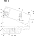
- the terminal device 1 shown in one embodiment has a connection device 2 which has a spring element 21 and realizes a spring force connection for connecting an electrical conductor 4.
- the terminal device 1 also has a busbar connection device 3, via which the terminal device 1 can be attached to a busbar 5 along an attachment direction A.
- connection device 2 is assigned a plug-in opening 20 formed in a housing 10 of the terminal device 1, into which an electrical conductor 4 with a (stripped) conductor end 40 can be inserted along a plug-in direction E in order to electrically contact the conductor 4 within the terminal device 1 with a contact element 22 and thus to connect it to the terminal device 1.
- connection device 2 has an active element 23 which is connected to a Actuating element 24 is operatively connected and can be adjusted via the actuating element 24 on the housing 10.
- the actuating element 24 is mounted on the housing 10 so as to be pivotable about a pivot axis S.
- bearing pins 102 are formed on the housing 10, which project axially along the pivot axis S on both sides of the housing 10 and each form a collar-shaped edge section 205 projecting radially to the pivot axis S, which partially engages over the actuating element 24, so that the actuating element 24 is mounted on the housing 10 so as to be pivotable about the pivot axis S via the bearing pins 102 and is also axially secured to the housing 10 via the edge sections 105 of the bearing pins 102.
- the actuating element 24 forms an actuating section 240, via which a user can press on the actuating element 24 in order to pivot the actuating element 24 along an actuating direction B about the pivot axis S relative to the housing 10.
- the pivot axis S is directed perpendicular to the plug-in direction E and also perpendicular to the attachment direction A, which is parallel to the plug-in direction E.
- the pivot axis S points parallel to a longitudinal axis L of a busbar 5 when the terminal device 1 is attached to the busbar 5 along the attachment direction A.
- Guide elements 104 in the form of outwardly projecting pin elements are formed on both sides of the housing 10.
- the guide elements 104 engage in guide sections 244 in the form of arcuate links on the actuating element 24, so that the actuating element 24 can be guided relative to the housing 10 and moved between defined positions, namely an actuated position according to Fig. 1 to 6A , 6B and a non-actuated position according to Fig. 7 to 10A , 10B is pivotable relative to the housing 10.
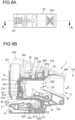
- the actuating element 24 is operatively connected to a base 233 of the active element 23 via a holding element 241 in the form of a hook element, as can be seen, for example, from the sectional view according to Fig. 6B can be seen. Furthermore, a pressing section 243 is formed on the actuating element 24, which cooperates with the base 233 of the active element 23. If the actuating element 24 is transferred from the non-actuated position to the actuated position and, for this purpose, pivoted in the actuating direction B relative to the housing 10, the actuating element 24 presses onto the base 233 of the active element 23 via the pressing section 243, thereby taking the active element 23 with it. In the actuated position the actuating element 24 is held in position relative to the housing 10 via the holding element 241 due to a locking of the active element 23.
- a preloading element 25 in the form of a mechanical compression spring acts between the actuating element 24 and a housing section 103 of the housing 10.
- the preloading element 25 is elastically tensioned, so that the return of the actuating element 24 from the actuated position to the non-actuated position is assisted by the preload of the preloading element 25.
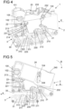
- the spring element 21 forms a clamping leg 210, which has two contact sections 212 formed laterally on the clamping leg by bent tabs and interacts via the contact sections 212 with contact contours 230 on legs 232 of the active element 23 and can thus be adjusted by adjusting the active element 23 relative to the housing 10, as can be seen, for example, from Fig. 4 is evident.
- the clamping leg 210 forms a clamping end 215 which is designed to cooperate with a conductor 4 inserted into the plug-in opening 20 in order to clamp the conductor 4 to a contacting section 220 of the contact element 22 and thus to electrically connect it to the connection device 2 and to mechanically lock it.
- the spring element 21 has a support leg 211, via which the spring element 21 is supported on the housing 10 in the illustrated embodiment and relative to which the clamping leg 210 is elastically deflectable. Via one end 216, the respective support leg 211 engages in an opening in the busbar 22 and is thus supported on the busbar 22.
- the support leg 211 can - alternatively or in addition to the support on the housing 10 - also be supported on the contact element 22, which is designed, for example, as a current bar.
- a locking element 214 is formed by a spring leg extending from the support leg 211.
- the locking element 214 forms locking sections 213, which, as can be seen from Fig. 4 visible, are designed to engage with counter-locking sections 231 of the active element 23 in order to hold the active element 23 in position relative to the housing 10 in an active position of the active element 23.
- the active element 23 is formed as a stamped and bent part and has two legs 232 bent to the base 233, on each of which a counter-locking section 231 is formed.
- locking elements 214 On the locking element 214, locking sections 213 are formed on both sides, which in the active position of the active element 23 according to Fig. 1 to 6A , 6B are engaged with the counter-locking sections 231 on the legs 232 of the active element 23 and thereby lock the active element 23 in the active position relative to the housing 10.
- the locking element 214 in the form of the spring leg is elastically deflectable to the support leg 211, so that when the active element 23 is transferred from an inactive position into the Fig. 1 to 6A , 6B In the active position shown, the locking element 214 is locked via the locking sections 213 with the counter-locking sections 231 of the active element 23 and the active element 23 is thus held in position relative to the housing 10.
- the clamping leg 210 of the spring element 21 is held in the release position on the legs 232 of the active element 23 via the contact contours 230 acting on the contact sections 212 of the clamping leg 210.
- the clamping leg 210 is thus removed from the contact section 220 of the contact element 22 with the clamping end 215, so that a space between the clamping leg 210 and the contact section 220 is released and a conductor 4 can be inserted into the plug-in opening 20 in a substantially forceless manner.
- the conductor end 40 of the conductor 4 comes into contact with the locking element 214 and thereby acts on the locking element 214 to release the locking of the locking sections 213 with the counter-locking sections 231 on the active element 23.
- the locking is thus automatically canceled, the active element 23 is released, and the hold of the clamping leg 210 in the release position is released, so that the clamping leg 210 can come into contact with the conductor 4 due to an elastic tension force on the spring element 21.
- the conductor 4 is thus clamped to the contacting section 220 and is thereby electrically connected to the contacting section 220 via the conductor end 40 and is also mechanically locked.
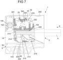
- Fig. 7 shows the terminal device 1 with conductor 4 connected to the connection device 2.
- a user can act on the actuating element 24 of the connection device 2 and move the active element 23 from the inactive position to the active position by pivoting the actuating element 24 in the actuating direction B.
- the clamping leg 210 of the spring element 21 is thereby carried along and transferred into the release position, in which the clamping leg 210 is held in position relative to the housing 10 by the locking of the active element 23 with the locking sections 213 of the locking element 214.
- the active element 23 of the connection device 2 is linearly displaceable within the housing 10 along a direction perpendicular to the pivot axis S and the plugging direction E.
- a user can act on the active element 23 from the outside via the actuating element 24 in order to transfer the active element 23 from the inactive position to the active position and thus move the clamping leg 210 from the clamping position to the release position.
- the active element 23 When transferred from the inactive position to the active position, the active element 23 automatically engages with the locking element 214 in the form of the spring leg of the spring element 21. Due to the operative connection of the actuating element 24 with the active element 23 via the holding element 241, the actuating element 24 is also held in the actuated position in position relative to the housing 10 due to the locking of the active element 23 relative to the housing 10, as can be seen from Fig. 1 to 6A , 6B is evident. If the locking is released when a conductor 4 is inserted, the actuating element 24 is returned to the non-actuated position due to the spring preload of the preload element 25, as can be seen from Fig. 7 is evident.
- the actuating element 24 engages with the pressing portion 243 in an opening 234 in the base 233 of the active element 23.
- the prestressing element 25 is supported on the one hand on the housing portion 103 of the housing 10 and on the other hand on the base 233 of the active element 23 and thus prestresses the active element 23 and thereby (indirectly) also the actuating element 24 relative to the housing 10.
- the biasing element 25 may be supported on the contact element 22 instead of being supported on the housing section 103.
- the terminal device 1 can be attached to an associated busbar 5 along the attachment direction A.
- the busbar 5 can be mounted stationary on an electrical system, for example, in a control cabinet.
- a connection option for connecting an electrical line 4 is created on the busbar 5, so that the electrical line 4 can be connected to the reference potential of the busbar 5.
- the busbar 5 is formed by a rod-shaped, solid, metal element.
- the busbar 5 is usually mounted stationary on an associated electrical system, for example, a control cabinet.
- the busbar connection device 3 of the terminal device 1 forms an attachment opening 30 formed on the housing 10, into which the busbar 5 can be engaged.
- the attachment opening 30 is designed to accommodate the busbar 5, which has a rectangular cross-section transverse to the longitudinal axis L.
- the contact element 22 is shaped such that it protrudes into the region of the attachment opening 30 in order to make contact with the busbar 5 within the attachment opening 30.
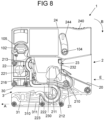
- the contact element 22 forms a C-shaped receptacle in the area of the attachment opening 30, which is formed by a contact section 222 and a clamping section 223, which, when the terminal device 1 is attached to the busbar 5, come to rest on opposite sides of the busbar 5, as can be seen, for example, from Fig. 12 can be seen. While the contact section 222 extends in a straight line in an area in which a contact with the busbar 5 is to be established, the clamping section 223 can be elastically deflected relative to the contact section 222, so that a contact force between the busbar 5 and the contact section 222 can be adjusted via the clamping section 223. In the attached position, the busbar 5 is clamped between the contact section 222 and the clamping section 223, so that a low-resistance electrical transition is established between the contact element 22 and the busbar 5.
- the contact section 222 is connected to the contacting section 220 of the contact element 22 via a connecting section 221.
- the support leg 211 of the spring element 21 is supported on the contact section 222.
- the support end 216 of the support leg 211 engages in an opening in the connecting section 221 for additional support of the spring element 21 relative to the contact element 22.
- the contact section 222 and the contacting section 220 extend parallel to one another along the plugging direction E and accommodate the spring element 21 between them.
- the active element 23 engages around the contacting section 220 with the legs 232 and is thus movable relative to the contacting section 220.
- the contact element 22 is designed as a bent metal part and enclosed in the housing 10 of the terminal device 1.
- the busbar connection device 5 has a locking element 31 which projects with a latching projection 310 into the region of the attachment opening 30 and is elastically connected to the housing 10 via a connecting section 311 such that the locking element 31 can be elastically deflected relative to the housing 10 along a direction perpendicular to the attachment direction A.
- the busbar 5 runs onto the locking element 31 and pushes the locking element 31 aside transversely to the attachment direction A.
- the locking element 31 snaps back into a relaxed starting position in which the locking projection 310 comes to lie in front of the busbar 5 with respect to the attachment direction A and the busbar 5 is thus locked in the attachment opening 30, as can be seen from Fig. 12 is evident.
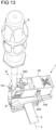
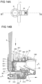
- a tool 6, for example in the form of a screwdriver, can be inserted into an insertion opening 101 of the housing 10, as shown in Fig. 13 and 14A, 14B
- the insertion opening 101 extends along an insertion direction X perpendicular to the application direction A and to the pivot axis S through the housing 10 and enables the tool 10 to be inserted in the insertion direction X into the housing 10 such that the tool 10 can be brought into operative connection with the locking element 31, as can be seen from the sectional view according to Fig. 14B is evident.
- a recess 242 of the actuating element 24 is aligned with the insertion opening 101, so that the actuating element 24 does not hinder the insertion of a tool 6 into the insertion opening 101.
- the locking element 31 By inserting a tool 6 in the insertion direction X and by pressing on the locking element 31, the locking element 31 can be inserted within the attachment opening 30 be deflected in order to bring the locking projection 310 out of its blocking, arresting position and thus release the busbar 5, so that the terminal device 1 can be removed from the busbar 5 opposite to the attachment direction A.
- a tool 6 can be easily brought into operative connection with the locking element 31 in order to remove the terminal device 1 from the busbar 5. No complex release mechanism, which would further increase the installation space required for the terminal device 1, is required.
- Fig. 15 shows another embodiment of a terminal device 1, which differs from the one described above with reference to FIG. 1 by the design of the locking element 31 of the busbar connection device 3.
- Fig. 1 to 14A , 14B The embodiment according to Fig. 15 the locking element 31 is formed integrally with the contact element 22 in that the locking element 31 is formed at an end of the contact element 22 protruding from the clamping section 223 and acts in a locking manner on the busbar 5 with a locking projection 310 in the form of a protruding tab in a locking position.
- the terminal device 1 is functionally identical to the one described above with reference to Fig. 1 to 14A , 14B described embodiment, so that reference should also be made to the explanations thereon.
- a terminal device may comprise one or more connection devices for connecting one or more conductors.
Landscapes
- Connections Arranged To Contact A Plurality Of Conductors (AREA)
- Details Of Connecting Devices For Male And Female Coupling (AREA)
Abstract
Eine Klemmeneinrichtung (1) zum Anschließen eines elektrischen Leiters (4) umfasst ein Kontaktelement (22), das einen Kontaktierungsabschnitt (220) aufweist, und eine Anschlusseinrichtung (2), die ein Federelement (21) mit einem Klemmschenkel (210) aufweist, der zwischen einer Klemmstellung und einer Freigabestellung verstellbar ist und ausgebildet ist, in der Klemmstellung klemmend auf den Leiter (4) zum elektrischen Kontaktieren des Leiters (4) mit dem Kontaktierungsabschnitt (220) des Kontaktelements (22) einzuwirken. Die Anschlusseinrichtung (2) weist ein Rastelement (214) auf, über das der Klemmschenkel (210) in der Freigabestellung in Position relativ zu dem Gehäuse (10) gehalten ist. Eine Sammelschienenanschlusseinrichtung (3) weist eine Ansetzöffnung (30) zum Ansetzen der Klemmeneinrichtung (1) entlang einer Ansetzrichtung (A) an eine Sammelschiene (5) auf, wobei das Kontaktelement (22) einen Anlageabschnitt (222) aufweist, mit dem die Sammelschiene (5) in einer an die Sammelschiene (5) angesetzten Stellung der Klemmeneinrichtung (1) in elektrisch kontaktierender Anlage ist.
Description
- Die Erfindung betrifft eine Klemmeneinrichtung zum Anschließen eines elektrischen Leiters nach dem Oberbegriff des Anspruchs 1.
- Eine derartige Klemmeneinrichtung umfasst ein Gehäuse, das eine Stecköffnung ausbildet, in die der elektrische Leiter in eine Steckrichtung zum Anschließen an die Klemmeneinrichtung einsteckbar ist. Ein Kontaktelement weist einen Kontaktierungsabschnitt auf. Eine Anschlusseinrichtung weist ein Federelement mit einem Klemmschenkel auf, der zwischen einer Klemmstellung und einer Freigabestellung verstellbar ist und ausgebildet ist, in der Klemmstellung klemmend auf den in die Stecköffnung eingesteckten Leiter zum elektrischen Kontaktieren des Leiters mit dem Kontaktierungsabschnitt des Kontaktelements einzuwirken, wobei der Klemmschenkel zum Einstecken des Leiters in die Stecköffnung oder zum Entnehmen des Leiters aus der Stecköffnung aus der Klemmstellung in die Freigabestellung bewegbar ist. Die Anschlusseinrichtung weist zudem ein Rastelement auf, über das der Klemmschenkel in der Freigabestellung in Position relativ zu dem Gehäuse gehalten ist, wobei das Rastelement bei Einstecken der elektrischen Leitung verstellbar ist, um den Klemmschenkel aus der Freigabestellung zu lösen.
- Die Anschlusseinrichtung der Klemmeneinrichtung verwirklicht durch Verwendung des Federelements einen Federkraftanschluss, bei dem der elektrische Leiter in angeschlossener Stellung mit dem Kontaktelement unter elastischer Federwirkung des Federelements verklemmt und somit elektrisch an das Kontaktelement angeschlossen ist.
- Während in der Klemmstellung der Klemmschenkel dem Kontaktierungsabschnitt so angenähert ist, dass ein in die Stecköffnung eingesteckter Leiter klemmend zwischen dem Klemmschenkel und dem Kontaktierungsabschnitt gehalten und somit elektrisch mit dem Kontaktierungsabschnitt kontaktiert und zudem vorzugsweise mechanisch an der Klemmeneinrichtung arretiert ist, kann der Klemmschenkel in eine Freigabestellung überführt werden, in der der Klemmschenkel von dem Kontaktierungsabschnitt entfernt ist und somit ein eingesteckter elektrischer Leiter von der Klemmeneinrichtung entnommen werden kann. In der Freigabestellung ist zudem ein Leiter in einer im Wesentlichen kraftlosen Weise an die Klemmeneinrichtung ansteckbar, wobei nach dem Einstecken der Klemmschenkel aus der Freigabestellung in die Klemmstellung überführt wird und somit der Leiter mit dem Kontaktierungsabschnitt verklemmt wird.
- Um ein einfaches Einstecken eines Leiters zu ermöglichen, ist der Klemmschenkel in der Freigabestellung über ein Rastelement in Position relativ zu dem Gehäuse gehalten. Beispielsweise kann vorgesehen sein, dass die Klemmeneinrichtung bei in der Freigabestellung befindlichem Klemmschenkel von einem Hersteller an einen Anwender ausgeliefert wird, sodass der Anwender in einfacher Weise eine elektrische Leitung an die Klemmeneinrichtung anschließen kann.
- Bei einer aus der
DE 10 2019 127 464 B3 bekannten Anschlusseinrichtung ist ein Federelement in Form einer Zugfeder vorgesehen, die eine angeschlossene elektrische Leitung durch elastische Federwirkung in Anlage mit einem zugeordneten Kontaktelement zieht und somit eine klemmende Verbindung zwischen der elektrischen Leitung und dem Kontaktelement herstellt. Die elektrische Leitung wird hierzu bei Ansetzen durch eine Öffnung in dem Klemmschenkel hindurchgeschoben und in angeschlossener Stellung zwischen dem Klemmschenkel und dem Kontaktelement verklemmt. - Bei der Anschlusseinrichtung der
DE 10 2019 127 464 B3 ist eine Rasteinrichtung vorgesehen, über die der Klemmschenkel in einer Freigabestellung relativ zu dem Gehäuse verrastet ist. Bei Einstecken der elektrischen Leitung wird die Rasteinrichtung ausgelöst und somit die Verrastung aufgehoben, sodass der Klemmschenkel aus der Freigabestellung verstellt wird und dadurch die elektrische Leitung mit dem Kontaktelement verklemmt. Um den Klemmschenkel in die Freigabestellung zu überführen, insbesondere um ein Ansetzen der elektrischen Leitung zu ermöglichen oder eine angeschlossene elektrische Leitung von der Anschlusseinrichtung zu lösen, kann ein Werkzeug, zum Beispiel ein Schraubendreher, an die Anschlusseinrichtung angesetzt und dadurch eine Kraft auf den Klemmschenkel ausgeübt werden. - Während bei der
DE 10 2019 127 464 B3 ein Verstellen des Klemmschenkels unmittelbar durch ein Werkzeug erfolgt, ist bei aus derDE 10 2019 135 203 A1 und derDE 10 2020 104 240 A1 bekannten Anschlusseinrichtungen jeweils ein Betätigungselement in Form eines sogenannten Drückers (Pushers) vorgesehen, der in das Gehäuse der Anschlusseinrichtung eingedrückt werden kann, um auf diese Weise auf den Klemmschenkel einzuwirken und den Klemmschenkel in seine Freigabestellung zu überführen. Das Betätigungselement ist jeweils über eine Spannfeder in Form einer Druckfeder gegenüber dem Gehäuse der Anschlusseinrichtung federvorgespannt. Bei der aus derDE 10 2019 135 203 A1 bekannten Anschlusseinrichtung ist hierbei an dem Betätigungselement eine Betätigungsnase angeordnet, die in betätigter Stellung des Betätigungselements an einem Befestigungsabschnitt eines Halteelements eingehakt ist. - Die
DE 10 2021 117 396 A1 beschreibt eine Anschlussanordnung zum Anschließen eines elektrischen Leiters, bei der eine Klemmfeder zwischen einer Klemmstellung und einer Offenstellung verstellbar ist. In der Klemmstellung ist der anzuschließende elektrische Leiter gegen einen Klemmabschnitt eines Strombalkens geklemmt. Ein entlang einer ersten Betätigungsrichtung führbares Betätigungselement dient dazu, die Klemmfeder von der Klemmstellung in die Offenstellung zu überführen. Ein drehbar gelagertes Hebelelement dient dazu, das Betätigungselement zu betätigen. - Die Anschlussanordnung der
DE 10 2021 117 396 A1 kann insbesondere bei einer Reihenklemme Verwendung finden. - Aus der
DE 10 2016 112 831 A1 ist eine Klemmeneinrichtung bekannt, die an eine Sammelschiene ansetzbar ist. - Aufgabe der vorliegenden Erfindung ist es, eine Klemmeneinrichtung zur Verfügung zu stellen, die ein einfaches, nach Möglichkeit werkzeugloses Anschließen an eine Sammelschiene ermöglicht.
- Diese Aufgabe wird durch einen Gegenstand mit den Merkmalen des Anspruchs 1 gelöst.
- Demnach weist die Klemmeneinrichtung eine Sammelschienenanschlusseinrichtung auf, die eine Ansetzöffnung zum Ansetzen der Klemmeneinrichtung entlang einer Ansetzrichtung an eine Sammelschiene aufweist, wobei das Kontaktelement einen Anlageabschnitt aufweist, mit dem die Sammelschiene in einer an die Sammelschiene angesetzten Stellung der Klemmeneinrichtung in elektrisch kontaktierender Anlage ist.
- Ein elektrischer Leiter kann an die Klemmeneinrichtung angeschlossen werden, indem der elektrische Leiter in die Stecköffnung des Gehäuses eingesteckt wird. Bei Einstecken des elektrischen Leiters befindet sich der Klemmschenkel des Federelements der Anschlusseinrichtung vorzugsweise in der Freigabestellung, sodass der elektrische Leiter in einer im Wesentlichen kraftlosen Weise in die Stecköffnung eingesteckt werden kann, ungehindert von dem Klemmschenkel. Ist der Leiter in die Stecköffnung eingesteckt, wird der Klemmschenkel aus der Freigabestellung in die Klemmstellung überführt, sodass der elektrische Leiter mit dem Kontaktierungsabschnitt verklemmt und somit elektrisch an den Kontaktierungsabschnitt des Kontaktelements angeschlossen und zudem vorzugsweise mechanisch an der Anschlusseinrichtung der Klemmeneinrichtung arretiert wird.
- Die Anschlusseinrichtung weist ein Rastelement zum Bereitstellen eines rastenden Halts an dem Klemmschenkel in der Freigabestellung auf. Das Rastelement kann unmittelbar oder mittelbar (über ein funktional zwischen dem Rastelement und dem Klemmschenkel angeordnetes Element) auf den Klemmschenkel einwirken, um dadurch den Klemmschenkel in der Freigabestellung in Position relativ zu dem Gehäuse zu halten.
- Wird ein elektrischer Leiter in die Stecköffnung des Gehäuses eingesteckt, wird dadurch das Rastelement ausgelöst und auf diese Weise der Klemmschenkel aus der Freigabestellung gelöst, sodass sich der Klemmschenkel des Federelements aufgrund einer Federvorspannung an dem Federelement in Richtung der Klemmstellung bewegt. Der Leiter wirkt somit klemmend auf den in die Stecköffnung eingesteckten elektrischen Leiter ein, um den Leiter mit dem Kontaktierungsabschnitt des Kontaktelements elektrisch zu kontaktieren und zudem mechanisch an der Anschlusseinrichtung der Klemmeneinrichtung zu arretieren.
- Weil das Rastelement bei Einstecken eines elektrischen Leiters selbsttätig auslöst und somit der Leiter bei Einstecken selbsttätig in Kontakt mit dem Kontaktierungsabschnitt des Kontaktelements gebracht wird, wird eine werkzeuglose Betätigung der Anschlusseinrichtung zum Anschließen eines elektrischen Leiters möglich. Um ein einfaches Anstecken des Leiters zu ermöglichen, kann der Klemmschenkel zum Beispiel über ein Betätigungselement in die Freigabestellung überführt werden, in der der Klemmschenkel über das Rastelement mittelbar oder unmittelbar relativ zu dem Gehäuse verrastet und somit in Position gehalten ist. Wird ein elektrischer Leiter bei in der Freigabestellung befindlichem Klemmschenkel an die Klemmeneinrichtung angeschlossen, indem der Leiter in die Stecköffnung des Gehäuses eingesteckt wird, löst der Klemmschenkel aus und kontaktiert den Leiter mit dem Kontaktierungsabschnitt des Kontaktelements.
- Die Klemmeneinrichtung weist, zusätzlich zu der Anschlusseinrichtung zum Anschließen eines elektrischen Leiters, eine Sammelschienenanschlusseinrichtung auf, die eine Ansetzöffnung zum Ansetzen der Klemmeneinrichtung entlang einer Ansetzrichtung an eine Sammelschiene aufweist. Das Kontaktelement weist einen Anlageabschnitt auf, mit dem die Sammelschiene in einer an die Sammelschiene angesetzten Stellung der Klemmeneinrichtung in elektrisch kontaktierender Anlage ist. Der an die Anschlusseinrichtung angeschlossene Leiter wird somit über das Kontaktelement, ausgestaltet zum Beispiel als Strombalken, mit der Sammelschiene kontaktiert und somit an die Sammelschiene angeschlossen.
- Bei einer Sammelschiene handelt es sich üblicherweise um ein stabförmiges Element, das entlang einer Längsachse längserstreckt ist und dabei als massives, elektrisch leitfähiges, metallenes Bauteil ausgebildet ist. Die Sammelschiene liegt auf einem Bezugspotenzial, zum Beispiel einem Nullleiterpotenzial, wobei eine Mehrzahl von Klemmeneinrichtungen gleicher oder unterschiedlicher Bauart an die Sammelschiene angesetzt und somit über die Sammelschiene auf ein gemeinsames, der Sammelschiene zugeordnetes Potenzial gebracht werden können.
- Das Ansetzen der Klemmeneinrichtung an die Sammelschiene erfolgt dadurch, dass die Ansetzöffnung mit der Sammelschiene in Eingriff gebracht wird. In angesetzter Stellung ist die Sammelschiene in der Ansetzöffnung aufgenommen, wobei innerhalb der Ansetzöffnung der Anlageabschnitt des Kontaktelements elektrisch mit der Sammelschiene in Kontakt ist und das Kontaktelement somit an die Sammelschiene elektrisch angeschlossen ist.
- Die Sammelschiene kann, um Querschnitt quer zu ihrer Längsachse, zum Beispiel rechteckförmig sein. Die Ansetzöffnung der Sammelschienenanschlusseinrichtung ist entsprechend zur Aufnahme einer im Querschnitt rechteckigen Sammelschiene ausgestaltet.
- Ein elektrischer Leiter wird zum Anschließen an die Anschlusseinrichtung der Klemmeneinrichtung in die Steckrichtung in die Stecköffnung des Gehäuses eingesteckt und dadurch mit dem Federelement innerhalb des Gehäuses in Wirkverbindung gebracht, indem das Rastelement ausgelöst und somit das Federelement aus der Freigabestellung gelöst wird. Das Ansetzen der Klemmeneinrichtung an die Sammelschiene erfolgt demgegenüber in die Ansetzrichtung. In einer Ausgestaltung sind hierbei die Steckrichtung und die Ansetzrichtung gleichgerichtet, sodass das Anschließen eines elektrischen Leiters an die Anschlusseinrichtung der Klemmeneinrichtung und das Ansetzen der Klemmeneinrichtung an eine (stationäre) Sammelschiene entlang einer gemeinsamen Richtung erfolgt.
- In einer Ausgestaltung weist die Anschlusseinrichtung ein zu dem Gehäuse verstellbares Wirkelement auf. Das Wirkelement ist in der Freigabestellung des Klemmschenkels mit dem Rastelement verrastet und ist dadurch in Position relativ zu dem Gehäuse gehalten.
- Das Wirkelement kann beispielsweise dazu dienen, direkt oder indirekt auf den Klemmschenkel einzuwirken. Durch Verstellen des Wirkelements kann der Klemmschenkel beispielsweise aus der Klemmstellung in die Freigabestellung überführt werden, wobei nach Überführen in die Freigabestellung das Wirkelement mit dem Rastelement verrastet und somit in Position relativ zu dem Gehäuse gehalten ist.
- Das Wirkelement kann insbesondere zwischen einer nicht aktiven Stellung und einer aktiven Stellung relativ zu dem Gehäuse bewegt werden, um den Klemmschenkel aus der Klemmstellung in die Freigabestellung zu überführen. In der aktiven Stellung befindet sich der Klemmschenkel in der Freigabestellung, wobei das Wirkelement über das Rastelement relativ zu dem Gehäuse verrastet und somit in Position relativ zu dem Gehäuse gehalten ist.
- In einer Ausgestaltung weist das Wirkelement eine Anlagekontur auf. An dem Klemmschenkel ist demgegenüber ein Anlageabschnitt geformt, der in der Freigabestellung mit der Anlagekontur in Anlage ist, um den Klemmschenkel in der Freigabestellung zu halten. Durch Verstellen des Wirkelements kann der Klemmschenkel insbesondere in die Freigabestellung überführt werden. Durch Anlage an dem Wirkelement wird der Klemmschenkel in der Freigabestellung gehalten, wobei das Wirkelement in der der Freigabestellung zugeordneten, aktiven Stellung über das Rastelement verrastet und somit in Position relativ zu dem Gehäuse gehalten ist.
- Der Anlageabschnitt ist zum Beispiel als Lasche an dem Klemmschenkel geformt. Beispielsweise kann der Anlageabschnitt an einem Rand des Klemmschenkels als eine relativ zu einem Klemmende des Klemmschenkels freigeschnittene, relativ zu dem Klemmende umgebogene Lasche geformt sein.
- In einer Ausgestaltung ist das Rastelement ausgebildet, bei Einstecken des Leiters mit dem Leiter zusammenzuwirken. Dadurch ist das Rastelement relativ zu dem Wirkelement bei Einstecken des Leiters verstellbar, um die Verrastung zwischen dem Wirkelement und dem Rastelement in der Freigabestellung des Klemmschenkels zu lösen. Bei Einstecken eines Leiters löst die Anschlusseinrichtung selbsttätig aus, indem der elektrische Leiter auf das Rastelement einwirkt und dadurch die Verrastung zwischen dem Wirkelement und dem Rastelement löst. Der Klemmschenkel wird somit freigegeben und kann sich aus der Freigabestellung in Richtung der Klemmstellung verstellen, sodass der Leiter selbsttätig an die Anschlusseinrichtung angeschlossen und dazu elektrisch mit dem Kontaktierungsabschnitt kontaktiert und zudem vorzugsweise mechanisch an der Anschlusseinrichtung arretiert wird.
- In einer Ausgestaltung ist das Wirkelement linear (geradlinig) relativ zu dem Gehäuse verschiebbar. In anderer Ausgestaltung kann das Wirkelement aber auch entlang einer gekrümmten Bewegungsbahn oder durch Verschwenken relativ zu dem Gehäuse bewegbar sein.
- Das Wirkelement ist, in einer Ausgestaltung, beispielsweise mit einem Betätigungselement wirkverbunden, das durch Nutzerbetätigung zum Überführen des Wirkelements in die aktive Stellung relativ zu dem Gehäuse bewegbar ist. Während das Wirkelement zum Beispiel als Stanzbiegeteil geformt sein kann und in dem Gehäuse aufgenommen ist, um in dem Gehäuse auf den Klemmschenkel einzuwirken und mit dem Rastelement zusammenzuwirken, kann das Betätigungselement beispielsweise von außen zugänglich sein und somit ein Betätigen des Wirkelements ermöglichen. Das Betätigungselement ist mit dem Wirkelement in Wirkverbindung derart, dass bei Betätigen des Betätigungselements das Wirkelement mitgenommen und somit relativ zu dem Gehäuse verschoben wird.
- Das Betätigungselement ist vorzugsweise werkzeuglos durch einen Nutzer betätigbar. Ein Nutzer kann zum Bewegen des Betätigungselements beispielsweise mit einem Finger auf das Betätigungselement einwirken und dadurch das Betätigungselement zum Einwirken auf das Wirkelement relativ zu dem Gehäuse verstellen. Es ergibt sich eine einfache, komfortable Handhabung durch einen Nutzer, der insbesondere nicht notwendigerweise über ein besonderes Werkzeug zum Betätigen des Betätigungselements verfügen muss.
- Das Betätigungselement kann insbesondere als Hebel ausgestaltet und schwenkbar an dem Gehäuse gelagert sein.
- Das Betätigungselement kann beispielsweise schwenkbar an dem Gehäuse gelagert sein. Das Betätigungselement ist somit als Hebelelement ausgestaltet und kann zu dem Gehäuse verschwenkt werden, um auf diese Weise auf das Wirkelement einzuwirken und dadurch über das Wirkelement den Klemmschenkel des Federelements aus der Klemmstellung in Richtung der Freigabestellung zu überführen. Durch Betätigung des Betätigungselements kann somit der Klemmschenkel aus der Klemmstellung in die Freigabestellung bewegt werden, wobei der Klemmschenkel in der Freigabestellung mittelbar über das Wirkelement in Position gehalten wird und somit in der Freigabestellung verbleibt.
- In einer Ausgestaltung ist das Betätigungselement um eine zu der Steckrichtung senkrechte Schwenkachse relativ zu dem Gehäuse schwenkbar. Das Wirkelement kann beispielsweise entlang einer zu der Steckrichtung und zu der Schwenkachse des Betätigungselements senkrechten Richtung linear an dem Gehäuse verstellbar sein. Der Klemmschenkel des Federelements ist in einer zur Schwenkachse des Betätigungselements senkrechten Schwenkebene relativ zu dem Gehäuse verschwenkbar. Die Schwenkachse kann hierbei so erstreckt sein, dass sie parallel zu einer Längsachse einer Sammelschiene gerichtet ist, die in der Ansetzöffnung der Klemmeneinrichtung bei an die Sammelschiene angesetzter Klemmeneinrichtung aufgenommen ist.
- Das Betätigungselement ist vorzugsweise mit dem Wirkelement wirkverbunden, zum Beispiel verrastet. Ist das Wirkelement nach Überführen des Klemmschenkels in die Freigabestellung über das Rastelement relativ zu dem Gehäuse verrastet, wird damit auch das Betätigungselement in einer betätigten Stellung in Position relativ zu dem Gehäuse gehalten. Wird der Klemmschenkel aus der Freigabestellung gelöst und bewegt sich der Klemmschenkel aufgrund der Federspannung an dem Federelement aus der Freigabestellung in Richtung der Klemmstellung, wird das Wirkelement mitgenommen und dadurch das Betätigungselement aus der betätigten Stellung in eine nicht betätigte Stellung bewegt.
- Dies kann auch für eine Zustandsanzeige verwendet werden, mittels derer ein Nutzer unmittelbar erkennen kann, ob nach Einstecken einer elektrischen Leitung die Anschlusseinrichtung ausgelöst hat.
- In einer Ausgestaltung weist das Gehäuse zumindest einen Lagerzapfen zum Lagern des Betätigungselements auf. Der zumindest eine Lagerzapfen steht zum Beispiel axial entlang der Schwenkachse relativ zu einem Gehäuseabschnitt des Gehäuses vor und weist einen radial mit Bezug auf die Schwenkachse vorstehenden Randabschnitt auf, mit dem der zumindest eine Lagerzapfen das Betätigungselement übergreift. Dadurch ist das Betätigungselement über den Lagerzapfen nicht nur schwenkbar an dem Gehäuse gelagert, sondern ist auch axial in seiner Position relativ zu dem Gehäuse gesichert, insbesondere derart, dass das Betätigungselement sich in axialer Richtung bei Kraftbeaufschlagung nicht (übermäßig) verformen kann.
- In einer Ausgestaltung ist das Betätigungselement über ein Vorspannelement, zum Beispiel in Form einer mechanischen Druckfeder, elastisch relativ zu dem Gehäuse vorgespannt. Beispielsweise kann das Vorspannelement gespannt werden, wenn das Betätigungselement aus der nicht betätigten Stellung in die betätigte Stellung bewegt wird, um den Klemmschenkel des Federelements über das mit dem Betätigungselement wirkverbundene Wirkelement aus der Klemmstellung in die Freigabestellung zu überführen. Ein Rückstellen des Betätigungselements aus der betätigten Stellung in die nicht betätigte Stellung wird somit durch eine mechanische Vorspannung des Vorspannelements unterstützt.
- Beispielsweise ist das Rastelement, in einer Ausgestaltung, einstückig mit dem Federelement geformt. Beispielsweise kann das Rastelement durch einen Federschenkel des Federelements geformt sein, der elastisch auslenkbar ist und somit insbesondere mit dem Wirkelement verrasten kann, um in der Freigabestellung des Klemmschenkels das Wirkelement in Position relativ zu dem Gehäuse zu halten.
- In einer Ausgestaltung weist das Federelement einen an dem Gehäuse und/oder dem Kontaktelement abgestützten Stützschenkel auf. Der Klemmschenkel ist elastisch relativ zu dem Stützschenkel auslenkbar. An dem Stützschenkel ist das Rastelement geformt, das in der Freigabestellung des Klemmschenkels zum Beispiel mit dem Wirkelement verrastet und somit das Wirkelement und darüber den Klemmschenkel in der Freigabestellung hält. Der Stützschenkel ist zum Festlegen des Federelements am Gehäuse abgestützt. Der Klemmschenkel kann beispielsweise an einem ersten Ende des Stützschenkels geformt sein, während das Rastelement durch einen Schenkel an einem von dem ersten Ende abliegenden, zweiten Ende des Stützschenkels geformt ist.
- Der Klemmschenkel ist elastisch zu dem Stützschenkel auslenkbar und kann somit zwischen der Klemmstellung und der Freigabestellung bewegt werden, wobei in der Freigabestellung der Klemmschenkel elastisch verspannt ist derart, dass eine Spannkraft in Richtung der Klemmstellung wirkt. Wird der Halt des Klemmschenkels in der Freigabestellung aufgehoben, gelangt der Klemmschenkel selbsttätig aufgrund der elastischen Spannkraft an dem Federelement in die Klemmstellung, um einen in die Stecköffnung des Gehäuses eingesteckten elektrischen Leiter mit dem Kontaktierungsabschnitt zu verklemmen und somit elektrisch an den Kontaktierungsabschnitt anzuschließen und zudem vorzugsweise mechanisch an der Anschlusseinrichtung zu arretieren.
- Auch das durch einen Federschenkel geformte Rastelement ist elastisch zu dem Stützschenkel auslenkbar, sodass das Rastelement bei Überführen des Wirkelements in die der Freigabestellung des Klemmschenkels zugeordnete, betätigte Stellung mit dem Wirkelement verrasten kann und somit in verrasteter Stellung das Wirkelement in Position relativ zu dem Gehäuse hält.
- In einer Ausgestaltung weist das Kontaktelement einen Spannabschnitt auf. Beispielsweise ist in der an die Sammelschiene angesetzten Stellung der Klemmeneinrichtung der Anlageabschnitt des Kontaktelements an einer ersten Seite der Sammelschiene angeordnet, während der Spannabschnitt sich an einer der ersten Seite abgewandten, zweiten Seite der Sammelschiene befindet. Der Anlageabschnitt und der Spannabschnitt liegen somit an unterschiedlichen Seiten an der Sammelschiene an. Beispielsweise kann das Kontaktelement durch den Anlageabschnitt und den Spannabschnitt eine C-förmige Aufnahme verwirklichen, innerhalb derer die Sammelschiene aufgenommen ist, wenn die Klemmeneinrichtung an die Sammelschiene angesetzt und die Sammelschiene in der Ansetzöffnung der Klemmeneinrichtung aufgenommen ist.
- Beispielsweise ist der Spannabschnitt elastisch relativ zu dem Anlageabschnitt auslenkbar, um die Sammelschiene relativ zu dem Anlageabschnitt vorzuspannen. Der Spannabschnitt ist einstückig an dem Kontaktelement und somit einstückig mit dem Anlageabschnitt geformt. An dem Spannabschnitt wird hierbei eine (gewisse) Elastizität bereitgestellt, über die eine Kontaktkraft zwischen der Sammelschiene und dem Kontaktelement eingestellt werden kann. Durch elastische Auslenkung des Spannabschnitts und somit durch Verspannen der Sammelschiene zwischen dem Anlageabschnitt und dem Spannabschnitt kann eine Kontaktkraft zwischen der Sammelschiene und dem Anlageabschnitt eingestellt werden, sodass ein vorteilhafter, niederohmiger elektrischer Übergang zwischen der Sammelschiene und dem Anlageabschnitt hergestellt wird.
- In einer Ausgestaltung weist die Sammelschienenanschlusseinrichtung ein Arretierungselement zum Arretieren der Klemmeneinrichtung an der Sammelschiene auf, das elastisch relativ zu dem Gehäuse verstellbar ist. Das Arretierungselement sichert die Klemmeneinrichtung an der Sammelschiene, wenn die Klemmeneinrichtung an die Sammelschiene angesetzt ist, sodass die Klemmeneinrichtung nicht ohne weiteres, jedenfalls nicht ohne Aufheben der Arretierung des Arretierungselements, von der Sammelschiene abgenommen werden kann.
- Insbesondere kann über das Arretierungselement die Verbindung der Klemmeneinrichtung mit der Sammelschiene formschlüssig gesichert werden, sodass die Klemmeneinrichtung, wenn sich das Arretierungselement in einer arretierenden Stellung befindet, formschlüssig an der Sammelschiene gehalten ist.
- Das Arretierungselement ist elastisch relativ zu dem Gehäuse verstellbar. Bei Ansetzen der Klemmeneinrichtung an die Sammelschiene kann das Arretierungselement ausweichen, um dann, wenn die Sammelschiene in der Ansetzöffnung der Klemmeneinrichtung aufgenommen ist, zurück in eine Ausgangsstellung zu schnappen und somit die Klemmeneinrichtung an der Sammelschiene zu arretieren.
- In einer Ausgestaltung weist das Gehäuse eine Einführöffnung auf, in das ein Werkzeug zum Einwirken auf das Arretierungselement einführbar ist. Über die Einführöffnung kann ein Werkzeug, zum Beispiel ein Schraubendreher, mit dem Arretierungselement in Wirkverbindung gebracht werden, um auf das Arretierungselement einzuwirken und das Arretierungselement aus der arretierenden Stellung zu lösen, sodass die Klemmeneinrichtung von der Sammelschiene abgenommen werden kann.
- Das Werkzeug ist vorzugsweise entlang einer von der Ansetzrichtung unterschiedlichen Einführrichtung in die Einführöffnung einführbar. Die Einführrichtung ist beispielsweise senkrecht zu der Ansetzrichtung und auch senkrecht zu einer Längsachse der in der Ansetzöffnung aufgenommenen Sammelschiene gerichtet. Das Werkzeug kann somit durch die Einführöffnung am Gehäuse durch das Gehäuse hindurch hin zu dem Arretierungselement der Sammelschienenanschlusseinrichtung geführt werden, um die Arretierung der Klemmeneinrichtung an der Sammelschiene aufzuheben. Die Einführöffnung kann insbesondere ein Zuführen eines Werkzeugs aus einer Richtung ermöglichen, aus der die Klemmeneinrichtung zum Beispiel in einem Schaltschrank leicht zugänglich ist und die insbesondere nicht mit einem angesteckten Leiter kollidiert.
- Dadurch, dass das Einführen des Werkzeugs durch die Einführöffnung in dem Gehäuse erfolgt, kann die Klemmeneinrichtung mit vergleichsweise kleinem Bauraum ausgestaltet sein, ohne dass das Erfordernis zum Betätigen des Arretierungselements durch ein Werkzeug zu einem nennenswerten zusätzlichen Bauraumbedarf führt.
- Das Arretierungselement ist, in einer Ausgestaltung, einstückig mit einem Gehäuseabschnitt des Gehäuses oder einstückig mit dem Kontaktelement geformt. Das Gehäuse kann zum Beispiel insgesamt einstückig aus einem Teil geformt sein. Das Arretierungselement kann in diesem Fall einstückig mit dem Gehäuse geformt sein. In anderer Ausgestaltung kann das Arretierungselement an dem Kontaktelement geformt sein, zum Beispiel an einem von dem Spannabschnitt des Kontaktelements abstehenden Ende, über das eine rastende, formschlüssige Verbindung zwischen der Sammelschiene und der Klemmeneinrichtung hergestellt werden kann.
- Der der Erfindung zugrunde liegende Gedanke soll nachfolgend anhand der in den Figuren dargestellten Ausführungsbeispiele näher erläutert werden. Es zeigen:
- Fig. 1
- eine Ansicht einer Klemmeneinrichtung, aufweisend eine Anschlusseinrichtung zum Anschließen eines elektrischen Leiters und eine Sammelschienenanschlusseinrichtung zum Ansetzen an eine Sammelschiene, in einer betätigten Stellung eines Betätigungselements;
- Fig. 2
- eine andere Ansicht der Klemmeneinrichtung;
- Fig. 3
- eine Seitenansicht der Klemmeneinrichtung;
- Fig. 4
- eine Ansicht der Klemmeneinrichtung, ohne einen Gehäusedeckel;
- Fig. 5
- eine Seitenansicht der Anordnung gemäß
Fig. 4 ; - Fig. 6A
- eine Draufsicht auf die Klemmeneinrichtung;
- Fig. 6B
- eine Schnittansicht entlang der Linie A-A gemäß
Fig. 6A ; - Fig. 7
- einen Teilschnittansicht der Klemmeneinrichtung, nach Einstecken eines elektrischen Leiters;
- Fig. 8
- eine Seitenansicht der Klemmeneinrichtung, vor Betätigung des Betätigungselements;
- Fig. 9A
- eine Draufsicht auf die Klemmeneinrichtung in der Stellung gemäß
Fig. 8 ; - Fig. 9B
- eine Schnittansicht entlang der Linie D-D gemäß
Fig. 9A ; - Fig. 10A
- eine Seitenansicht der Klemmeneinrichtung in der Stellung gemäß
Fig. 8 ; - Fig. 10B
- eine Schnittansicht entlang der Linie B-B gemäß
Fig. 10A ; - Fig. 10C
- eine Schnittansicht entlang der Linie C-C gemäß
Fig. 10A ; - Fig. 11
- eine Ansicht der Klemmeneinrichtung, bei Ansetzen an eine Sammelschiene;
- Fig. 12
- eine Ansicht der Klemmeneinrichtung in einer an die Sammelschiene angesetzten Stellung;
- Fig. 13
- eine Ansicht der Klemmeneinrichtung, bei Verwendung eines Werkzeugs zum Lösen der Klemmeneinrichtung von der Sammelschiene;
- Fig. 14A
- eine Draufsicht der Anordnung gemäß
Fig. 13 ; - Fig. 14B
- eine Schnittansicht entlang der Linie B-B gemäß
Fig. 14A ; und - Fig. 15
- eine Seitenansicht eines anderen Ausführungsbeispiels einer Klemmeneinrichtung.
- Eine in
Fig. 1 bis 14A ,14B in einem Ausführungsbeispiel dargestellte Klemmeneinrichtung 1 weist eine Anschlusseinrichtung 2 auf, die ein Federelement 21 aufweist und einen Federkraftanschluss zum Anschließen eines elektrischen Leiters 4 verwirklicht. - Die Klemmeneinrichtung 1 weist zudem eine Sammelschienenanschlusseinrichtung 3 auf, über die die Klemmeneinrichtung 1 entlang einer Ansetzrichtung A an eine Sammelschiene 5 angesetzt werden kann.
- Der Anschlusseinrichtung 2 ist eine in einem Gehäuse 10 der Klemmeneinrichtung 1 geformte Stecköffnung 20 zugeordnet, in die ein elektrischer Leiter 4 mit einem (abisolierten) Leiterende 40 entlang einer Steckrichtung E eingesteckt werden kann, um auf diese Weise den Leiter 4 innerhalb der Klemmeneinrichtung 1 elektrisch mit einem Kontaktelement 22 zu kontaktieren und somit an die Klemmeneinrichtung 1 anzuschließen.
- Wie aus
Fig. 4 und 5 in Zusammenschau mit der Schnittansicht gemäßFig. 6B ersichtlich ist, weist die Anschlusseinrichtung 2 ein Wirkelement 23 auf, das mit einem Betätigungselement 24 wirkverbunden ist und über das Betätigungselement 24 an dem Gehäuse 10 verstellt werden kann. - Das Betätigungselement 24 ist um eine Schwenkachse S schwenkbar an dem Gehäuse 10 gelagert. An dem Gehäuse 10 sind hierzu Lagerzapfen 102 geformt, die axial entlang der Schwenkachse S beidseitig an dem Gehäuse 10 vorstehen und jeweils einen radial zur Schwenkachse S vorstehenden, kragenförmigen Randabschnitt 205 ausbilden, der das Betätigungselement 24 abschnittsweise übergreift, sodass das Betätigungselement 24 über die Lagerzapfen 102 schwenkbar um die Schwenkachse S an dem Gehäuse 10 gelagert und zudem über die Randabschnitte 105 der Lagerzapfen 102 axial an dem Gehäuse 10 gesichert ist.
- Das Betätigungselement 24 bildet einen Betätigungsabschnitt 240 aus, über den ein Nutzer an dem Betätigungselement 24 drücken kann, um das Betätigungselement 24 entlang einer Betätigungsrichtung B um die Schwenkachse S relativ zu dem Gehäuse 10 zu verschwenken. Die Schwenkachse S ist senkrecht zu der Steckrichtung E und auch senkrecht zu der der Steckrichtung E gleichgerichteten Ansetzrichtung A gerichtet. Die Schwenkachse S weist parallel zu einer Längsachse L einer Sammelschiene 5, wenn die Klemmeneinrichtung 1 entlang der Ansetzrichtung A an die Sammelschiene 5 angesetzt ist.
- An dem Gehäuse 10 sind beidseits Führungselemente 104 in Form von nach außen vorstehenden Zapfenelementen geformt. Die Führungselemente 104 greifen in Führungsabschnitte 244 in Form von bogenförmigen Kulissen an dem Betätigungselement 24 ein, sodass darüber das Betätigungselement 24 relativ zu dem Gehäuse 10 geführt und zwischen definierten Stellungen, nämlich einer betätigten Stellung gemäß
Fig. 1 bis 6A ,6B und einer nicht betätigten Stellung gemäßFig. 7 bis 10A ,10B relativ zu dem Gehäuse 10 verschwenkbar ist. - Das Betätigungselement 24 ist über ein Halteelement 241 in Form eines Hakenelements mit einer Basis 233 des Wirkelements 23 wirkverbunden, wie dies zum Beispiel aus der Schnittansicht gemäß
Fig. 6B ersichtlich ist. An dem Betätigungselement 24 ist zudem ein Drückabschnitt 243 geformt, der mit der Basis 233 des Wirkelements 23 zusammenwirkt. Wird das Betätigungselement 24 aus der nicht betätigten Stellung in die betätigte Stellung überführt und dazu in die Betätigungsrichtung B relativ zu dem Gehäuse 10 verschwenkt, so drückt das Betätigungselement 24 über den Drückabschnitt 243 auf die Basis 233 des Wirkelements 23 und nimmt dadurch das Wirkelement 23 mit. In der betätigten Stellung wird das Betätigungselement 24 über das Halteelement 241 aufgrund einer Verrastung des Wirkelements 23 in Position relativ zu dem Gehäuse 10 gehalten. - Zwischen dem Betätigungselement 24 und einem Gehäuseabschnitt 103 des Gehäuses 10 wirkt ein Vorspannelement 25 in Form einer mechanischen Druckfeder. Bei Überführen des Betätigungselements 24 in die betätigte Stellung wird das Vorspannelement 25 elastisch gespannt, sodass ein Rückstellen des Betätigungselements 24 aus der betätigten Stellung in die nicht betätigte Stellung durch die Vorspannung des Vorspannelements 25 unterstützt wird.
- Das Federelement 21 bildet einen Klemmschenkel 210 aus, der zwei seitlich an dem Klemmschenkel durch umgebogene Laschen geformte Anlageabschnitte 212 aufweist und über die Anlageabschnitte 212 mit Anlagekonturen 230 an Schenkeln 232 des Wirkelements 23 zusammenwirkt und somit durch Verstellen des Wirkelements 23 relativ zum Gehäuse 10 verstellt werden kann, wie dies zum Beispiel aus
Fig. 4 ersichtlich ist. - Der Klemmschenkel 210 bildet ein Klemmende 215 aus, das dazu ausgestaltet ist, mit einem in die Stecköffnung 20 eingesteckten Leiter 4 zusammenzuwirken, um den Leiter 4 mit einem Kontaktierungsabschnitt 220 des Kontaktelements 22 zu verklemmen und somit elektrisch an die Anschlusseinrichtung 2 anzuschließen und mechanisch zu arretieren.
- Das Federelement 21 weist einen Stützschenkel 211 auf, über den das Federelement 21 bei dem dargestellten Ausführungsbeispiel an dem Gehäuse 10 abgestützt ist und relativ zu dem der Klemmschenkel 210 elastisch auslenkbar ist. Über ein Ende 216 greift der jeweilige Stützschenkel 211 in eine Öffnung an der Stromschiene 22 ein und ist somit an der Stromschiene 22 abgestützt.
- In einem anderen Ausführungsbeispiel kann der Stützschenkel 211 - alternativ oder zusätzlich zu der Abstützung an dem Gehäuse 10 - auch an dem zum Beispiel als Strombalken ausgebildeten Kontaktelement 22 abgestützt sein.
- An dem Federelement 21 der Anschlusseinrichtung 2 ist ein Rastelement 214 durch einen von dem Stützschenkel 211 erstreckten Federschenkel geformt. Das Rastelement 214 bildet Rastabschnitte 213 aus, die, wie aus
Fig. 4 ersichtlich, dazu ausgestaltet sind, mit Gegenrastabschnitten 231 des Wirkelements 23 zu verrasten, um in einer aktiven Stellung des Wirkelements 23 das Wirkelement 23 in Position relativ zu dem Gehäuse 10 zu halten. - Das Wirkelement 23 ist als Stanz-Biege-Teil geformt und weist zwei zu der Basis 233 umgebogene Schenkel 232 auf, an denen jeweils ein Gegenrastabschnitt 231 geformt ist. An dem Rastelement 214 sind beidseitig Rastabschnitte 213 geformt, die in der aktiven Stellung des Wirkelements 23 gemäß
Fig. 1 bis 6A ,6B mit den Gegenrastabschnitten 231 an den Schenkeln 232 des Wirkelements 23 in Eingriff sind und dadurch das Wirkelement 23 in der aktiven Stellung relativ zu dem Gehäuse 10 verrasten. - Das Rastelement 214 in Form des Federschenkels ist elastisch zu dem Stützschenkel 211 auslenkbar, sodass bei Überführen des Wirkelements 23 aus einer nicht aktiven Stellung in die in
Fig. 1 bis 6A ,6B dargestellte, aktive Stellung das Rastelement 214 über die Rastabschnitte 213 mit den Gegenrastabschnitten 231 des Wirkelements 23 verrastet und das Wirkelement 23 somit in Position relativ zu dem Gehäuse 10 gehalten wird. - Befindet sich das Wirkelement 23 in der aktiven Stellung und ist das Wirkelement 23 über das Rastelement 214 relativ zu dem Gehäuse 10 verrastet, so wird der Klemmschenkel 210 des Federelements 21 über die auf die Anlageabschnitte 212 des Klemmschenkels 210 einwirkenden Anlagekonturen 230 an den Schenkeln 232 des Wirkelements 23 in der Freigabestellung gehalten. Der Klemmschenkel 210 ist somit mit dem Klemmende 215 von dem Kontaktierungsabschnitt 220 des Kontaktelements 22 entfernt, sodass ein Raum zwischen dem Klemmschenkel 210 und dem Kontaktierungsabschnitt 220 freigegeben ist und ein Leiter 4 in einer im Wesentlichen kraftlosen Weise in die Stecköffnung 20 eingesteckt werden kann.
- Wird der Leiter 4 in die Stecköffnung 20 der jeweiligen Anschlusseinrichtung 2 eingeführt, so gelangt der Leiter 4 mit dem Leiterende 40 mit dem Rastelement 214 in Anlage und wirkt dadurch auf das Rastelement 214 ein, um die Verrastung der Rastabschnitte 213 mit den Gegenrastabschnitten 231 an dem Wirkelement 23 zu lösen. Bei Einstecken eines elektrischen Leiters 4 wird die Verrastung somit selbsttätig aufgehoben, das Wirkelement 23 freigegeben und der Halt des Klemmschenkels 210 in der Freigabestellung gelöst, sodass der Klemmschenkel 210 aufgrund einer elastischen Spannkraft an dem Federelement 21 in Anlage mit dem Leiter 4 kommen kann. Der Leiter 4 wird somit mit dem Kontaktierungsabschnitt 220 verklemmt und dadurch elektrisch über das Leiterende 40 an den Kontaktierungsabschnitt 220 angeschlossen und zudem mechanisch arretiert.
-
Fig. 7 zeigt die Klemmeneinrichtung 1 bei an die Anschlusseinrichtung 2 angeschlossenem Leiter 4. - Soll ein angeschlossener Leiter 4 aus der Anschlusseinrichtung 2 wieder entnommen werden, so kann ein Nutzer auf das Betätigungselement 24 der Anschlusseinrichtung 2 einwirken und durch Verschwenken des Betätigungselements 24 in die Betätigungsrichtung B das Wirkelement 23 aus der nicht aktiven Stellung in die aktive Stellung bewegen. Der Klemmschenkel 210 des Federelements 21 wird dabei mitgenommen und in die Freigabestellung überführt, in der der Klemmschenkel 210 durch die Verrastung des Wirkelements 23 mit den Rastabschnitten 213 des Rastelements 214 in Position relativ zu dem Gehäuse 10 gehalten wird.
- Bei dem dargestellten Ausführungsbeispiel ist das Wirkelement 23 der Anschlusseinrichtung 2 innerhalb des Gehäuses 10 linear entlang einer zu der Schwenkachse S und der Steckrichtung E senkrechten Richtung verschiebbar. Über das Betätigungselement 24 kann ein Nutzer von außen auf das Wirkelement 23 einwirken, um dadurch das Wirkelement 23 aus der nicht aktiven Stellung in die aktive Stellung zu überführen und somit den Klemmschenkel 210 aus der Klemmstellung in die Freigabestellung zu bewegen.
- Bei Überführen aus der nicht aktiven Stellung in die aktive Stellung verrastet das Wirkelement 23 selbsttätig mit dem Rastelement 214 in Form des Federschenkels des Federelements 21. Aufgrund der Wirkverbindung des Betätigungselements 24 mit dem Wirkelement 23 über das Halteelement 241 wird aufgrund der Verrastung des Wirkelements 23 relativ zu dem Gehäuse 10 auch das Betätigungselement 24 in der betätigten Stellung in Position relativ zu dem Gehäuse 10 gehalten, wie dies aus
Fig. 1 bis 6A ,6B ersichtlich ist. Wird die Verrastung bei Einstecken eines Leiters 4 aufgehoben, so wird das Betätigungselement 24 aufgrund der Federvorspannung des Vorspannelements 25 in die nicht betätigte Stellung zurückgestellt, wie dies ausFig. 7 ersichtlich ist. - Das Betätigungselement 24 greift mit dem Drückabschnitt 243 in eine Öffnung 234 in der Basis 233 des Wirkelements 23 ein. Das Vorspannelement 25 ist einerseits an dem Gehäuseabschnitt 103 des Gehäuses 10 und andererseits an der Basis 233 des Wirkelements 23 abgestützt und spannt somit das Wirkelement 23 und darüber (indirekt) auch das Betätigungselement 24 relativ zu dem Gehäuse 10 vor.
- In einem anderen Ausführungsbeispiel kann das Vorspannelement 25 - anstelle der Abstützung an dem Gehäuseabschnitt 103 - an dem Kontaktelement 22 abgestützt sein.
- Über die Sammelschienenanschlusseinrichtung 3 kann die Klemmeneinrichtung 1 entlang der Ansetzrichtung A an eine zugeordnete Sammelschiene 5 angesetzt werden. Die Sammelschiene 5 kann hierbei stationär an einer elektrischen Anlage, zum Beispiel in einem Schaltschrank, montiert sein. Durch Ansetzen der Klemmeneinrichtung 1 an die Sammelschiene 5 wird an der Sammelschiene 5 eine Anschlussmöglichkeit zum Anschließen einer elektrischen Leitung 4 geschaffen, sodass die elektrische Leitung 4 an das Bezugspotenzial der Sammelschiene 5 angeschlossen werden kann.
- Wie dies aus
Fig. 11 bis 14A ,14B ersichtlich ist, ist die Sammelschiene 5 durch ein stabförmiges, massives, metallenes Element ausgebildet. Die Sammelschiene 5 ist üblicherweise stationär an einer zugeordneten elektrischen Anlage, zum Beispiel einem Schaltschrank, montiert. - Die Sammelschienenanschlusseinrichtung 3 der Klemmeneinrichtung 1 bildet eine an dem Gehäuse 10 geformte Ansetzöffnung 30 aus, mit der die Sammelschiene 5 in Eingriff gebracht werden kann. Der Ansetzöffnung 30 ist zur Aufnahme der im Querschnitt quer zur Längsachse L rechteckigen Sammelschiene 5 ausgestaltet, wobei das Kontaktelement 22 so geformt ist, dass es in den Bereich der Ansetzöffnung 30 ragt, um innerhalb der Ansetzöffnung 30 mit der Sammelschiene 5 zu kontaktieren.
- Das Kontaktelement 22 bildet im Bereich der Ansetzöffnung 30 eine C-förmige Aufnahme aus, die durch einen Anlageabschnitt 222 und einen Spannabschnitt 223 gebildet ist, die bei an die Sammelschiene 5 angesetzter Klemmeneinrichtung 1 an einander abgewandten Seiten der Sammelschiene 5 zu liegen kommen, wie dies beispielsweise aus
Fig. 12 ersichtlich ist. Während der Anlageabschnitt 222 in einem Bereich, in der eine Anlage mit der Sammelschiene 5 hergestellt werden soll, geradlinig erstreckt ist, ist der Spannabschnitt 223 elastisch zu dem Anlageabschnitt 222 auslenkbar, sodass über den Spannabschnitt 223 eine Kontaktkraft zwischen der Sammelschiene 5 und dem Anlageabschnitt 222 eingestellt werden kann. In angesetzter Stellung ist die Sammelschiene 5 zwischen dem Anlageabschnitt 222 und dem Spannabschnitt 223 verspannt, sodass ein niederohmiger elektrischer Übergang zwischen dem Kontaktelement 22 und der Sammelschiene 5 hergestellt ist. - Der Anlageabschnitt 222 ist über einen Verbindungsabschnitt 221 mit dem Kontaktierungsabschnitt 220 des Kontaktelements 22 verbunden. An dem Anlageabschnitt 222 ist der Stützschenkel 211 des Federelements 21 abgestützt. In eine Öffnung an dem Verbindungsabschnitt 221 greift das Stützende 216 des Stützschenkels 211 zur zusätzlichen Abstützung des Federelements 21 relativ zu dem Kontaktelement 22 ein. Der Anlageabschnitt 222 und der Kontaktierungsabschnitt 220 erstrecken sich parallel zueinander entlang der Steckrichtung E und nehmen zwischen sich das Federelement 21 auf. Das Wirkelement 23 umgreift mit den Schenkeln 232 den Kontaktierungsabschnitt 220 und ist somit relativ zu dem Kontaktierungsabschnitt 220 bewegbar.
- Das Kontaktelement 22 ist als gebogenes Metallteil ausgestaltet und in dem Gehäuse 10 der Klemmeneinrichtung 1 eingefasst.
- Die Sammelschienenanschlusseinrichtung 5 weist ein Arretierungselement 31 auf, das mit einem Rastvorsprung 310 in den Bereich der Ansetzöffnung 30 ragt und über einen Verbindungsabschnitt 311 elastisch mit dem Gehäuse 10 verbunden ist derart, dass das Arretierungselement 31 elastisch entlang einer zur Ansetzrichtung A senkrechten Richtung relativ zu dem Gehäuse 10 auslenkbar ist. Bei Ansetzen der Klemmeneinrichtung 1 an eine Sammelschiene 5 läuft die Sammelschiene 5 auf das Arretierungselement 31 auf und drängt das Arretierungselement 31 quer zur Ansetzrichtung A beiseite. Hat die Sammelschiene 5 den Rastvorsprung 310 des Arretierungselements 31 passiert, so schnappt das Arretierungselement 31 zurück in eine entspannte Ausgangsstellung, in der der Rastvorsprung 310 mit Bezug auf die Ansetzrichtung A vor der Sammelschiene 5 zu liegen kommt und die Sammelschiene 5 somit in der Ansetzöffnung 30 arretiert ist, wie dies aus
Fig. 12 ersichtlich ist. - Um die Klemmeneinrichtung 1 von der Sammelschiene 5 zu lösen, kann ein Werkzeug 6, zum Beispiel in Form eines Schraubendrehers, in eine Einführöffnung 101 des Gehäuses 10 eingeführt werden, wie dies aus
Fig. 13 und14A, 14B ersichtlich ist. Die Einführöffnung 101 erstreckt sich entlang einer zu der Ansetzrichtung A und zu der Schwenkachse S senkrechten Einführrichtung X durch das Gehäuse 10 hindurch und ermöglicht ein Einführen des Werkzeugs 10 in die Einführrichtung X in das Gehäuse 10 derart, dass das Werkzeug 10 mit dem Arretierungselement 31 in Wirkverbindung gebracht werden kann, wie dies aus der Schnittansicht gemäßFig. 14B ersichtlich ist. - Mit der Einführöffnung 101 fluchtet eine Aussparung 242 des Betätigungselements 24, sodass das Betätigungselement 24 das Einführen eines Werkzeugs 6 in die Einführöffnung 101 nicht behindert.
- Durch Einführen eines Werkzeugs 6 in die Einführrichtung X und durch Drücken auf das Arretierungselement 31 kann das Arretierungselement 31 innerhalb der Ansetzöffnung 30 ausgelenkt werden, um den Rastvorsprung 310 aus seiner sperrenden, arretierenden Stellung zu bringen und die Sammelschiene 5 somit freizugeben, sodass die Klemmeneinrichtung 1 entgegen der Ansetzrichtung A von der Sammelschiene 5 abgenommen werden kann.
- Weil die Einführöffnung 101 senkrecht zur Ansetzrichtung A durch das Gehäuse 10 hindurch erstreckt ist, kann ein Werkzeug 6 in einfacher Weise mit dem Arretierungselement 31 in Wirkverbindung gebracht werden, um die Klemmeneinrichtung 1 von der Sammelschiene 5 abzunehmen. Es ist kein aufwendiger Lösemechanismus, der einen Bauraumbedarf der Klemmeneinrichtung 1 zusätzlich vergrößern würde, erforderlich.
-
Fig. 15 zeigt ein anderes Ausführungsbeispiel einer Klemmeneinrichtung 1, das sich durch die Ausgestaltung des Arretierungselements 31 der Sammelschienenanschlusseinrichtung 3 von dem vorangehend anhand vonFig. 1 bis 14A ,14B beschriebenen Ausführungsbeispiel unterscheidet. So ist bei dem Ausführungsbeispiel gemäßFig. 15 das Arretierungselement 31 einstückig mit dem Kontaktelement 22 geformt, indem das Arretierungselement 31 an einem von dem Spannabschnitt 223 vorstehenden Ende des Kontaktelements 22 geformt ist und mit einem Rastvorsprung 310 in Form einer vorstehenden Lasche in einer arretierenden Stellung sperrend auf die Sammelschiene 5 einwirkt. - Im Übrigen, insbesondere mit Blick auf die Ausgestaltung der Anschlusseinrichtung 2, ist die Klemmeneinrichtung 1 in funktionaler Hinsicht identisch mit dem vorangehend anhand von
Fig. 1 bis 14A ,14B beschriebenen Ausführungsbeispiel, sodass auch auf die Erläuterungen hierzu verwiesen werden soll. - Der der Erfindung zugrunde liegende Gedanke ist nicht auf die vorangehend geschilderten Ausführungsbeispiele beschränkt, sondern lässt sich auch in anderer Weise verwirklichen.
- Eine Klemmeneinrichtung kann ein oder mehrere Anschlusseinrichtungen zum Anschließen eines oder mehrerer Leiter aufweisen.
-
- 1
- Abgriffklemme
- 10
- Gehäuse
- 100
- Gehäuseabschnitt
- 101
- Einführöffnung
- 102
- Lagerzapfen
- 103
- Gehäuseabschnitt
- 104
- Führungselement
- 105
- Randabschnitt
- 2
- Anschlusseinrichtung
- 20
- Stecköffnung
- 21
- Federelement
- 210
- Klemmschenkel
- 211
- Stützschenkel
- 212
- Anlageabschnitt
- 213
- Rastabschnitt
- 214
- Rastelement
- 215
- Klemmende
- 216
- Stützende
- 22
- Kontaktelement (Strombalken)
- 220
- Kontaktierungsabschnitt
- 221
- Abschnitt
- 222
- Anlageabschnitt
- 223
- Spannabschnitt
- 23
- Wirkelement
- 230
- Anlagekontur
- 231
- Gegenrastabschnitt
- 232
- Schenkel
- 233
- Basis
- 234
- Öffnung
- 24
- Betätigungselement
- 240
- Betätigungsabschnitt
- 241
- Halteelement
- 242
- Öffnung
- 243
- Drückabschnitt
- 244
- Führungsabschnitt (Führungskulisse)
- 25
- Vorspannelement (Feder)
- 3
- Sammelschienenanschlusseinrichtung
- 30
- Ansetzöffnung
- 31
- Arretierungselement
- 310
- Rastvorsprung
- 311
- Verbindungsabschnitt
- 4
- Leiter
- 40
- Leiterende
- 5
- Sammelschiene
- 6
- Werkzeug
- A
- Ansetzrichtung
- B
- Betätigungsrichtung
- E
- Steckrichtung
- L
- Längsachse
- S
- Schwenkachse
- X
- Einführrichtung
Claims (15)
- Klemmeneinrichtung (1) zum Anschließen eines elektrischen Leiters (4), miteinem Gehäuse (10), das eine Stecköffnung (20) ausbildet, in die der elektrische Leiter (4) in eine Steckrichtung (E) zum Anschließen an die Klemmeneinrichtung (1) einsteckbar ist,einem Kontaktelement (22), das einen Kontaktierungsabschnitt (220) aufweist, undeiner Anschlusseinrichtung (2), die ein Federelement (21) mit einem Klemmschenkel (210) aufweist, der zwischen einer Klemmstellung und einer Freigabestellung verstellbar ist und ausgebildet ist, in der Klemmstellung klemmend auf den in die Stecköffnung (20) eingesteckten Leiter (4) zum elektrischen Kontaktieren des Leiters (4) mit dem Kontaktierungsabschnitt (220) des Kontaktelements (22) einzuwirken, wobei der Klemmschenkel (210) zum Einstecken des Leiters (4) in die Stecköffnung (20) oder zum Entnehmen des Leiters (4) aus der Stecköffnung (20) aus der Klemmstellung in die Freigabestellung bewegbar ist,wobei die Anschlusseinrichtung (2) ein Rastelement (214) aufweist, über das der Klemmschenkel (210) in der Freigabestellung in Position relativ zu dem Gehäuse (10) gehalten ist, wobei das Rastelement (214) bei Einstecken der elektrischen Leitung (4) verstellbar ist, um den Klemmschenkel (210) aus der Freigabestellung zu lösen,gekennzeichnet durch eine Sammelschienenanschlusseinrichtung (3), die eine Ansetzöffnung (30) zum Ansetzen der Klemmeneinrichtung (1) entlang einer Ansetzrichtung (A) an eine Sammelschiene (5) aufweist, wobei das Kontaktelement (22) einen Anlageabschnitt (222) aufweist, mit dem die Sammelschiene (5) in einer an die Sammelschiene (5) angesetzten Stellung der Klemmeneinrichtung (1) in elektrisch kontaktierender Anlage ist.
- Klemmeneinrichtung (1) nach Anspruch 1, dadurch gekennzeichnet, dass die Steckrichtung (E) und die Ansetzrichtung (A) gleichgerichtet sind.
- Klemmeneinrichtung (1) nach Anspruch 1 oder 2, dadurch gekennzeichnet, dass die Anschlusseinrichtung (2) ein zu dem Gehäuse (10) verstellbares Wirkelement (23) zum Einwirken auf den Klemmschenkel (210) aufweist, wobei das Wirkelement (23) in der Freigabestellung des Klemmschenkels (210) mit dem Rastelement (214) verrastet und dadurch in Position relativ zu dem Gehäuse (10) gehalten ist.
- Klemmeneinrichtung (1) nach Anspruch 3, dadurch gekennzeichnet, dass das Wirkelement (23) eine Anlagekontur (230) aufweist, wobei an dem Klemmschenkel (210) ein Anlageabschnitt (212) geformt ist, der in der Freigabestellung mit der Anlagekontur (230) in Anlage ist, um den Klemmschenkel (210) in der Freigabestellung zu halten.
- Klemmeneinrichtung (1) nach Anspruch 3 oder 4, dadurch gekennzeichnet, dass das Rastelement (214) ausgebildet ist, bei Einstecken des Leiters (4) mit dem Leiter (4) zusammenzuwirken, und das Rastelement (214) dadurch relativ zu dem Wirkelement (23) verstellbar ist, um die Verrastung zwischen dem Wirkelement (23) und dem Rastelement (214) in der Freigabestellung des Klemmschenkels (210) zu lösen.
- Klemmeneinrichtung (1) nach einem der Ansprüche 3 bis 5, dadurch gekennzeichnet, dass das Wirkelement (23) linear relativ zu dem Gehäuse (10) verschiebbar ist.
- Klemmeneinrichtung (1) nach einem der Ansprüche 3 bis 6, dadurch gekennzeichnet, dass die Anschlusseinrichtung (2) ein durch einen Nutzer betätigbares Betätigungselement (24) aufweist, wobei das Wirkelement (23) zum Einwirken auf den Klemmschenkel (210) durch Nutzerbetätigung des Betätigungselements (24) relativ zu dem Gehäuse (10) bewegbar ist.
- Klemmeneinrichtung (1) nach Anspruch 7, dadurch gekennzeichnet, dass das Betätigungselement (24) schwenkbar an dem Gehäuse (10) gelagert ist.
- Klemmeneinrichtung (1) nach Anspruch 7 oder 8, dadurch gekennzeichnet, dass das Betätigungselement (24) um eine zu der Steckrichtung (E) senkrechte Schwenkachse (S) relativ zu dem Gehäuse (10) schwenkbar ist.
- Klemmeneinrichtung (1) nach einem der Ansprüche 7 bis 9, dadurch gekennzeichnet, dass das Gehäuse (10) zumindest einen Lagerzapfen (102) zum Lagern des Betätigungselements (24) aufweist, wobei der zumindest eine Lagerzapfen (102) einen radial vorspringenden Randabschnitt (105) aufweist, mit dem der zumindest eine Lagerzapfen (102) das Betätigungselement (24) übergreift.
- Klemmeneinrichtung (1) nach einem der Ansprüche 7 bis 10, dadurch gekennzeichnet, dass das Betätigungselement (24) über ein Vorspannelement (25) elastisch relativ zu dem Gehäuse (10) vorgespannt ist.
- Klemmeneinrichtung (1) nach einem der vorangehenden Ansprüche, dadurch gekennzeichnet, dass das Rastelement (214) einstückig mit dem Federelement (21) geformt ist.
- Klemmeneinrichtung (1) nach einem der vorangehenden Ansprüche, dadurch gekennzeichnet, dass das Federelement (21) einen an dem Gehäuse (10) und/oder dem Kontaktelement (22) abgestützten Stützschenkel (211) aufweist, zu dem der Klemmschenkel (210) elastisch auslenkbar ist und an dem das Rastelement (214) geformt ist.
- Klemmeneinrichtung (1) nach einem der vorangehenden Ansprüche, dadurch gekennzeichnet, dass das Kontaktelement (22) einen Spannabschnitt (223) aufweist, wobei in der an die Sammelschiene (5) angesetzten Stellung der Klemmeneinrichtung (1) der Anlageabschnitt (222) an einer ersten Seite der Sammelschiene (5) und der Spannabschnitt (223) an einer der ersten Seite abgewandten, zweiten Seite der Sammelschiene (5) angeordnet ist.
- Klemmeneinrichtung (1) nach Anspruch 14, dadurch gekennzeichnet, dass der Spannabschnitt (223) elastisch relativ zu dem Anlageabschnitt (222) auslenkbar ist, um die Sammelschiene (5) relativ zu dem Anlageabschnitt (222) vorzuspannen.
Applications Claiming Priority (1)
| Application Number | Priority Date | Filing Date | Title |
|---|---|---|---|
| LU505691A LU505691B1 (de) | 2023-12-04 | 2023-12-04 | Klemmeneinrichtung zum Anschließen eines elektrischen Leiters |
Publications (1)
| Publication Number | Publication Date |
|---|---|
| EP4568021A1 true EP4568021A1 (de) | 2025-06-11 |
Family
ID=89157983
Family Applications (1)
| Application Number | Title | Priority Date | Filing Date |
|---|---|---|---|
| EP24217018.1A Pending EP4568021A1 (de) | 2023-12-04 | 2024-12-03 | Klemmeneinrichtung zum anschliessen eines elektrischen leiters |
Country Status (3)
| Country | Link |
|---|---|
| EP (1) | EP4568021A1 (de) |
| CN (1) | CN120109554A (de) |
| LU (1) | LU505691B1 (de) |
Citations (8)
| Publication number | Priority date | Publication date | Assignee | Title |
|---|---|---|---|---|
| DE10158948A1 (de) * | 2001-12-03 | 2003-06-12 | Wago Verwaltungs Gmbh | Sammelanschluss für elektr. Verteileranlagen |
| EP1322000A2 (de) * | 2001-12-21 | 2003-06-25 | Weidmüller Interface GmbH & Co. | Sammelschienen-Anschlussklemme |
| DE102013105263B3 (de) * | 2013-05-23 | 2014-09-11 | Wago Verwaltungsgesellschaft Mbh | Steckverbinder |
| DE102013107292B4 (de) * | 2013-07-10 | 2016-09-15 | Wago Verwaltungsgesellschaft Mbh | Steckverbinder |
| DE102016112831A1 (de) | 2016-07-13 | 2018-01-18 | Phoenix Contact Gmbh & Co. Kg | Anschlussklemme |
| DE102019127464B3 (de) | 2019-10-11 | 2021-03-25 | Phoenix Contact Gmbh & Co. Kg | Anschlusseinrichtung zum Anschließen einer elektrischen Leitung |
| DE102019135203A1 (de) | 2019-12-19 | 2021-06-24 | Phoenix Contact Gmbh & Co. Kg | Anschlussanordnung, Anschlusseinrichtung sowie elektronisches Gerät |
| DE102021117396A1 (de) | 2021-07-06 | 2023-01-12 | Phoenix Contact Gmbh & Co. Kg | Anschlussanordnung, Anschlussklemme und elektronisches Gerät |
-
2023
- 2023-12-04 LU LU505691A patent/LU505691B1/de active IP Right Grant
-
2024
- 2024-12-03 CN CN202411759221.7A patent/CN120109554A/zh active Pending
- 2024-12-03 EP EP24217018.1A patent/EP4568021A1/de active Pending
Patent Citations (8)
| Publication number | Priority date | Publication date | Assignee | Title |
|---|---|---|---|---|
| DE10158948A1 (de) * | 2001-12-03 | 2003-06-12 | Wago Verwaltungs Gmbh | Sammelanschluss für elektr. Verteileranlagen |
| EP1322000A2 (de) * | 2001-12-21 | 2003-06-25 | Weidmüller Interface GmbH & Co. | Sammelschienen-Anschlussklemme |
| DE102013105263B3 (de) * | 2013-05-23 | 2014-09-11 | Wago Verwaltungsgesellschaft Mbh | Steckverbinder |
| DE102013107292B4 (de) * | 2013-07-10 | 2016-09-15 | Wago Verwaltungsgesellschaft Mbh | Steckverbinder |
| DE102016112831A1 (de) | 2016-07-13 | 2018-01-18 | Phoenix Contact Gmbh & Co. Kg | Anschlussklemme |
| DE102019127464B3 (de) | 2019-10-11 | 2021-03-25 | Phoenix Contact Gmbh & Co. Kg | Anschlusseinrichtung zum Anschließen einer elektrischen Leitung |
| DE102019135203A1 (de) | 2019-12-19 | 2021-06-24 | Phoenix Contact Gmbh & Co. Kg | Anschlussanordnung, Anschlusseinrichtung sowie elektronisches Gerät |
| DE102021117396A1 (de) | 2021-07-06 | 2023-01-12 | Phoenix Contact Gmbh & Co. Kg | Anschlussanordnung, Anschlussklemme und elektronisches Gerät |
Also Published As
| Publication number | Publication date |
|---|---|
| LU505691B1 (de) | 2025-06-05 |
| CN120109554A (zh) | 2025-06-06 |
Similar Documents
| Publication | Publication Date | Title |
|---|---|---|
| EP3235061B1 (de) | Elektrische anschlussklemme | |
| EP3652808B1 (de) | Anschlusseinrichtung zum anschliessen einer elektrischen leitung | |
| EP2878040B1 (de) | Anschluss- oder verbindungsklemme mit einem drücker zur betätigung eines federelements | |
| DE102022121524A1 (de) | Anschlussklemme zum Anschließen einer elektrischen Leitung | |
| EP4358310A1 (de) | Anschlussklemme zum anschliessen einer elektrischen leitung | |
| DE102024119436A1 (de) | Anschlussklemme zum Anschließen einer elektrischen Leitung | |
| DE102022118234A1 (de) | Anschlussklemme zum Anschließen einer elektrischen Leitung | |
| DE102016112831B4 (de) | Anschlussklemme | |
| DE102022118237A1 (de) | Anschlussklemme zum Anschließen einer elektrischen Leitung | |
| EP3813198A1 (de) | Anschlusseinrichtung zum anschliessen einer elektrischen leitung | |
| DE102020119128A1 (de) | Steckverbindermodul zum Anschließen einer Schutzleitung | |
| DE102022120908A1 (de) | Anschlussklemme zum Anschließen einer elektrischen Leitung | |
| LU505691B1 (de) | Klemmeneinrichtung zum Anschließen eines elektrischen Leiters | |
| EP3714511B1 (de) | Anschlusseinrichtung zum anschliessen einer elektrischen leitung | |
| LU505692B1 (de) | Klemmeneinrichtung zum Anschließen eines elektrischen Leiters | |
| DE102021100100A1 (de) | Anschlusseinrichtung zum Anschließen einer elektrischen Leitung | |
| DE102023133799A1 (de) | Klemmeneinrichtung zum Anschließen eines elektrischen Leiters | |
| DE102023133800A1 (de) | Klemmeneinrichtung zum Anschließen eines elektrischen Leiters | |
| LU507360B1 (de) | Anschlussklemme zum Anschließen einer elektrischen Leitung | |
| LU508002B1 (de) | Anschlussklemme zum Anschließen einer elektrischen Leitung | |
| LU502846B1 (de) | Anschlussklemme zum Anschließen elektrischer Leitungen | |
| LU502683B1 (de) | Anschlussklemme zum Anschließen einer elektrischen Leitung | |
| DE102023135615A1 (de) | Anschlussklemme zum Anschließen einer elektrischen Leitung | |
| DE102024114957A1 (de) | Anschlussklemme zum Anschließen einer elektrischen Leitung | |
| DE102023135614A1 (de) | Anschlussklemme zum Anschließen einer elektrischen Leitung |
Legal Events
| Date | Code | Title | Description |
|---|---|---|---|
| PUAI | Public reference made under article 153(3) epc to a published international application that has entered the european phase |
Free format text: ORIGINAL CODE: 0009012 |
|
| STAA | Information on the status of an ep patent application or granted ep patent |
Free format text: STATUS: THE APPLICATION HAS BEEN PUBLISHED |
|
| AK | Designated contracting states |
Kind code of ref document: A1 Designated state(s): AL AT BE BG CH CY CZ DE DK EE ES FI FR GB GR HR HU IE IS IT LI LT LU LV MC ME MK MT NL NO PL PT RO RS SE SI SK SM TR |
|
| STAA | Information on the status of an ep patent application or granted ep patent |
Free format text: STATUS: REQUEST FOR EXAMINATION WAS MADE |
|
| 17P | Request for examination filed |
Effective date: 20251210 |