EP4567971A1 - Kühlkörperanordnung - Google Patents
Kühlkörperanordnung Download PDFInfo
- Publication number
- EP4567971A1 EP4567971A1 EP24815863.6A EP24815863A EP4567971A1 EP 4567971 A1 EP4567971 A1 EP 4567971A1 EP 24815863 A EP24815863 A EP 24815863A EP 4567971 A1 EP4567971 A1 EP 4567971A1
- Authority
- EP
- European Patent Office
- Prior art keywords
- heat sink
- flow path
- outlet
- flow paths
- inlet
- Prior art date
- Legal status (The legal status is an assumption and is not a legal conclusion. Google has not performed a legal analysis and makes no representation as to the accuracy of the status listed.)
- Pending
Links
Images


Classifications
-
- H—ELECTRICITY
- H01—ELECTRIC ELEMENTS
- H01M—PROCESSES OR MEANS, e.g. BATTERIES, FOR THE DIRECT CONVERSION OF CHEMICAL ENERGY INTO ELECTRICAL ENERGY
- H01M10/00—Secondary cells; Manufacture thereof
- H01M10/60—Heating or cooling; Temperature control
- H01M10/65—Means for temperature control structurally associated with the cells
- H01M10/655—Solid structures for heat exchange or heat conduction
- H01M10/6554—Rods or plates
-
- F—MECHANICAL ENGINEERING; LIGHTING; HEATING; WEAPONS; BLASTING
- F28—HEAT EXCHANGE IN GENERAL
- F28D—HEAT-EXCHANGE APPARATUS, NOT PROVIDED FOR IN ANOTHER SUBCLASS, IN WHICH THE HEAT-EXCHANGE MEDIA DO NOT COME INTO DIRECT CONTACT
- F28D1/00—Heat-exchange apparatus having stationary conduit assemblies for one heat-exchange medium only, the media being in contact with different sides of the conduit wall, in which the other heat-exchange medium is a large body of fluid, e.g. domestic or motor car radiators
- F28D1/02—Heat-exchange apparatus having stationary conduit assemblies for one heat-exchange medium only, the media being in contact with different sides of the conduit wall, in which the other heat-exchange medium is a large body of fluid, e.g. domestic or motor car radiators with heat-exchange conduits immersed in the body of fluid
- F28D1/03—Heat-exchange apparatus having stationary conduit assemblies for one heat-exchange medium only, the media being in contact with different sides of the conduit wall, in which the other heat-exchange medium is a large body of fluid, e.g. domestic or motor car radiators with heat-exchange conduits immersed in the body of fluid with plate-like or laminated conduits
- F28D1/0308—Heat-exchange apparatus having stationary conduit assemblies for one heat-exchange medium only, the media being in contact with different sides of the conduit wall, in which the other heat-exchange medium is a large body of fluid, e.g. domestic or motor car radiators with heat-exchange conduits immersed in the body of fluid with plate-like or laminated conduits the conduits being formed by paired plates touching each other
- F28D1/035—Heat-exchange apparatus having stationary conduit assemblies for one heat-exchange medium only, the media being in contact with different sides of the conduit wall, in which the other heat-exchange medium is a large body of fluid, e.g. domestic or motor car radiators with heat-exchange conduits immersed in the body of fluid with plate-like or laminated conduits the conduits being formed by paired plates touching each other with U-flow or serpentine-flow inside the conduits
-
- F—MECHANICAL ENGINEERING; LIGHTING; HEATING; WEAPONS; BLASTING
- F28—HEAT EXCHANGE IN GENERAL
- F28F—DETAILS OF HEAT-EXCHANGE AND HEAT-TRANSFER APPARATUS, OF GENERAL APPLICATION
- F28F1/00—Tubular elements; Assemblies of tubular elements
- F28F1/02—Tubular elements of cross-section which is non-circular
- F28F1/022—Tubular elements of cross-section which is non-circular with multiple channels
-
- F—MECHANICAL ENGINEERING; LIGHTING; HEATING; WEAPONS; BLASTING
- F28—HEAT EXCHANGE IN GENERAL
- F28F—DETAILS OF HEAT-EXCHANGE AND HEAT-TRANSFER APPARATUS, OF GENERAL APPLICATION
- F28F3/00—Plate-like or laminated elements; Assemblies of plate-like or laminated elements
- F28F3/12—Elements constructed in the shape of a hollow panel, e.g. with channels
-
- H—ELECTRICITY
- H01—ELECTRIC ELEMENTS
- H01M—PROCESSES OR MEANS, e.g. BATTERIES, FOR THE DIRECT CONVERSION OF CHEMICAL ENERGY INTO ELECTRICAL ENERGY
- H01M10/00—Secondary cells; Manufacture thereof
- H01M10/60—Heating or cooling; Temperature control
- H01M10/61—Types of temperature control
- H01M10/613—Cooling or keeping cold
-
- H—ELECTRICITY
- H01—ELECTRIC ELEMENTS
- H01M—PROCESSES OR MEANS, e.g. BATTERIES, FOR THE DIRECT CONVERSION OF CHEMICAL ENERGY INTO ELECTRICAL ENERGY
- H01M10/00—Secondary cells; Manufacture thereof
- H01M10/60—Heating or cooling; Temperature control
- H01M10/62—Heating or cooling; Temperature control specially adapted for specific applications
- H01M10/625—Vehicles
-
- H—ELECTRICITY
- H01—ELECTRIC ELEMENTS
- H01M—PROCESSES OR MEANS, e.g. BATTERIES, FOR THE DIRECT CONVERSION OF CHEMICAL ENERGY INTO ELECTRICAL ENERGY
- H01M10/00—Secondary cells; Manufacture thereof
- H01M10/60—Heating or cooling; Temperature control
- H01M10/65—Means for temperature control structurally associated with the cells
- H01M10/655—Solid structures for heat exchange or heat conduction
- H01M10/6556—Solid parts with flow channel passages or pipes for heat exchange
-
- H—ELECTRICITY
- H01—ELECTRIC ELEMENTS
- H01M—PROCESSES OR MEANS, e.g. BATTERIES, FOR THE DIRECT CONVERSION OF CHEMICAL ENERGY INTO ELECTRICAL ENERGY
- H01M10/00—Secondary cells; Manufacture thereof
- H01M10/60—Heating or cooling; Temperature control
- H01M10/65—Means for temperature control structurally associated with the cells
- H01M10/656—Means for temperature control structurally associated with the cells characterised by the type of heat-exchange fluid
- H01M10/6567—Liquids
-
- F—MECHANICAL ENGINEERING; LIGHTING; HEATING; WEAPONS; BLASTING
- F28—HEAT EXCHANGE IN GENERAL
- F28D—HEAT-EXCHANGE APPARATUS, NOT PROVIDED FOR IN ANOTHER SUBCLASS, IN WHICH THE HEAT-EXCHANGE MEDIA DO NOT COME INTO DIRECT CONTACT
- F28D21/00—Heat-exchange apparatus not covered by any of the groups F28D1/00 - F28D20/00
- F28D2021/0019—Other heat exchangers for particular applications; Heat exchange systems not otherwise provided for
- F28D2021/0028—Other heat exchangers for particular applications; Heat exchange systems not otherwise provided for for cooling heat generating elements, e.g. for cooling electronic components or electric devices
- F28D2021/0029—Heat sinks
-
- F—MECHANICAL ENGINEERING; LIGHTING; HEATING; WEAPONS; BLASTING
- F28—HEAT EXCHANGE IN GENERAL
- F28F—DETAILS OF HEAT-EXCHANGE AND HEAT-TRANSFER APPARATUS, OF GENERAL APPLICATION
- F28F2255/00—Heat exchanger elements made of materials having special features or resulting from particular manufacturing processes
- F28F2255/16—Heat exchanger elements made of materials having special features or resulting from particular manufacturing processes extruded
-
- H10W40/47—
-
- Y—GENERAL TAGGING OF NEW TECHNOLOGICAL DEVELOPMENTS; GENERAL TAGGING OF CROSS-SECTIONAL TECHNOLOGIES SPANNING OVER SEVERAL SECTIONS OF THE IPC; TECHNICAL SUBJECTS COVERED BY FORMER USPC CROSS-REFERENCE ART COLLECTIONS [XRACs] AND DIGESTS
- Y02—TECHNOLOGIES OR APPLICATIONS FOR MITIGATION OR ADAPTATION AGAINST CLIMATE CHANGE
- Y02E—REDUCTION OF GREENHOUSE GAS [GHG] EMISSIONS, RELATED TO ENERGY GENERATION, TRANSMISSION OR DISTRIBUTION
- Y02E60/00—Enabling technologies; Technologies with a potential or indirect contribution to GHG emissions mitigation
- Y02E60/10—Energy storage using batteries
Definitions
- the present disclosure relates to a heat sink assembly mounted to a bottom surface of a battery pack having a plurality of secondary batteries to facilitate heat dissipation of the battery pack.
- Secondary batteries are categorized into coin type batteries, cylindrical batteries, prismatic batteries, and pouch type batteries according to the shape of the battery case.
- an electrode assembly mounted inside the battery case is a chargeable and dischargeable power generating device comprising a stacked structure of electrodes and separators.
- heat sinks also called cooling plates
- the heat sink is mounted on the bottom surface of a group of secondary batteries, such as a battery pack mounting a plurality of secondary batteries and performs a cooling function by absorbing heat generated inside the pack with a coolant and releasing it to the outside.
- Heat sinks can be divided into brazing heat sinks and extruded heat sinks according to their structure or manufacturing method.
- a brazing heat sink is a structure in which two plates are brazed together to form a flow path, which has a high degree of freedom in flow path design but has a disadvantage in structural rigidity due to material degradation.
- extruded heat sinks which are manufactured as a continuum through extrusion molding, have an advantage in structural rigidity, but have the disadvantage that only straight flow paths can be realized, resulting in a large number of ports, and thus, pipes for connection take up space.
- the present disclosure is directed to providing a heat sink assembly that is an extruded heat sink and does not require a separate pipe for flow path formation, thereby occupying less space, and can improve differential pressure by reducing the number of components with a simplified flow path configuration, and uniformly inducing a rate of flow of coolant flowing in a plurality of flow paths.
- the present disclosure relates to a heat sink assembly includes a heat sink having a plurality of flow paths are integrally molded along an length direction by extrusion molding, the spaces between the flow paths forming a solid part, a first surface and a second surface of both ends in the length direction are opened, and both ends of the flow paths are spaced apart from the first surface and the second surface, and end plugs closing the opened first surface and second surface of both ends of the heat sink, respectively, wherein the first surface is disposed with an inlet port through which the coolant flows in and an outlet port through which the coolant flows out, and the second surface forms a return flow path of the coolant.
- an inlet flow path connected to the inlet port is disposed in a central region of the heat sink, and a pair of the outlet ports are provided such that the outlet flow paths connected to the outlet ports may be disposed on both sides of the inlet flow path.
- the end plug may comprise an inlet plug closing a first surface of the inlet flow path, a pair of outlet plugs closing a first surface of the outlet flow path, and a return flow plug closing a second surface of the return flow path.
- the plurality of outlet flow paths may have a separation distance from the first surface that gradually decreases as the plurality of the outlet flow paths becomes closer to the inlet port.
- the plurality of outlet flow paths may have a separation distance from the first surface that decreases linearly as the plurality of outlet flow paths becomes closer to the outlet port.
- the return flow path may have a constant separation distance from the second surface.
- the plurality of outlet flow paths wherein the pressure loss acting on the coolant flowing through the return flow path of the second surface to each of the plurality of outlet flow paths is proportional to the overall length of the outlet flow path, thereby uniformizing the rate of flow of the coolant flowing in each of the outlet flow paths.
- an expanded solid part may be provided between the inlet flow path and the outlet flow path adjacent to the inlet flow path.
- the pack structures may be mechanically coupled.
- a cross-sectional area in the length direction of the space between the inlet plug and the inlet flow path may be larger than a cross-sectional area in the length direction of the inlet flow path.
- coolant flowing out from each of the pair of outlet ports may be joined into one by a pipe member.
- the heat sink assembly of aspects of the present disclosure having the configuration as described above, has excellent structural rigidity because the heat sink is manufactured as a continuum by extrusion molding, meanwhile, it can comprise a cooling passage divided into an inlet and an outlet by performing machining processing on both ends in the length direction of the flow path integrally formed in the heat sink and closing the open surface with an end plug.
- the heat sink assembly of aspects of the present disclosure while having an extruded heat sink as a basic framework which is advantageous in structural rigidity, occupies less space by not requiring a separate pipe for forming the flow path, can improve the differential pressure by reducing the number of components with a simplified flow path configuration, and can obtain stable cooling performance throughout the overall heat dissipating area by uniformly inducing the rate of flow of the coolant flowing in the plurality of flow paths.
- the present disclosure relates to a heat sink assembly includes a heat sink having a plurality of flow paths are integrally molded along an length direction by extrusion molding, the spaces between the flow paths forming a solid part, a first surface and a second surface of both ends in the length direction are opened, and both ends of the flow paths are spaced apart from the first surface and the second surface, and end plugs closing the opened first surface and second surface of both ends of the heat sink, respectively, wherein the first surface is disposed with an inlet port through which the coolant flows in and an outlet port through which the coolant flows out, and the second surface forms a return flow path of the coolant.
- the heat sink assembly of aspects of the present disclosure having the above configuration is manufactured as a continuum by extrusion molding to possess excellent structural rigidity, meanwhile, and comprise a cooling passage divided into an inlet and an outlet by performing machining processing on both ends in the length direction of the flow path integrally formed in the heat sink and closing the open surface with an end plug.
- the heat sink assembly of aspects of the present disclosure while having an extruded heat sink as a basic framework which is advantageous in structural rigidity, occupies less space by not requiring a separate pipe for forming the flow path, can improve differential pressure by reducing the number of components with a simplified flow path configuration.
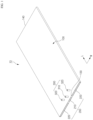
- FIG. 1 is a drawing illustrating a heat sink assembly according to one aspect of the present disclosure
- FIG. 2 is an exploded perspective view of the heat sink assembly of FIG. 1
- FIG. 3 is a drawing illustrating the structure of a heat sink in detail.
- the heat sink assembly 10 of aspects of the present disclosure includes a heat sink 100 manufactured by extrusion molding, and a plurality of end plugs 200.
- the open surfaces of the heat sink 100 are surfaces on both ends in a length direction L.
- the two open surfaces will be referred to as a first surface 130 and a second surface 140, respectively.
- the length direction L is defined as referring to the extrusion molding direction of the heat sink 100, in other words, the direction in which the plurality of flow paths 110 formed as hollow parts extend
- the width direction W is defined as referring to the direction in which the plurality of flow paths 110 are spaced apart and orthogonal to the length direction L on a plane.
- the heat sink 100 is manufactured as an extrusion in which a plurality of flow paths 110 are integrally molded along an length direction L by extrusion molding.
- the plurality of flow paths 110 in which the coolant flows are hollow parts formed along the length direction L, and the space between the flow paths 110 forms a solid part 120.
- the first surface 130 and the second surface 140 on both ends in the length direction L of the heat sink 100 are opened because of the features of the extrusion molding.
- FIG. 3 the structure of the flow path 110 is illustrated in more detail.
- a plurality of flow paths 110 extending in a length direction L between the first surface 130 and the second surface 140, the ends of which are separated from the first surface 130 and the second surface 140 by a predetermined distance.
- the separation distance of the flow paths 110 from the first surface 130 and the second surface 140 can be freely designed by a cutting processing that removes the flow paths 110, which are hollow parts, and the solid part 120 therebetween.
- a depth in which the end plugs 200 are to be inserted is obtained.
- the end plugs 200 close the opened first surface 130 and second surface 140 at both ends of the heat sink 100, respectively.
- the end plugs 200 have a thickness and width suitable for insertion into the openings on the first surface 130 and second surface 140 of the heat sink 100.
- the end plugs 200 inserted into the heat sink 100 may be sealed bonded by welding, for example, friction stir welding. If the welding depths of the friction stir welding performed on the upper and lower surfaces of the heat sink 100 are such that they overlap each other, a seal is completed by forming welding surfaces on up, down, left and right sides of the end plug 200.
- the heat sink assembly 10 can be configured to enable the flow of coolant across the overall heat transfer area of the heat sink assembly 10 by appropriately selecting the positions of the ports 300 through which the coolant flows in and out.
- the present disclosure includes an inlet port 310 through which coolant flows in and an outlet port 320 through which coolant flows out on the first surface 130, and the ports 300 are disposed such that the second surface 140 forms a return flow path 116 for coolant without separate ports.
- FIG. 4 is an enlarged view of "A" part of FIG. 1 , examined in conjunction with FIG. 3 , wherein an inlet flow path 112 connected to an inlet port 310 is disposed in a central region of the heat sink 100, a pair of outlet ports 320 are provided, and outlet flow paths 114 connected to the outlet ports 320 are disposed on both sides in the width direction W of the inlet flow path 112.
- two the inlet flow paths 112 are provided, and the terminals of the inlet flow path 112 are connected with a return flow path 116 elongated along the second surface 140, and the return flow path 116 is connected with the outlet flow paths 114 of both sides.
- the end plugs 200 closing the first surface 130 includes an inlet plug 210 closing the first surface 130 of the inlet flow path 112, and a pair of outlet plugs 220 closing the first surface 130 of the outlet flow path 114.
- a certain space is formed between the inlet plug 210 and the inlet flow path 112, and an inlet port 310 is disposed on this space. Accordingly, the coolant flowed in the inlet port 310 fills the space of the upstream side of the inlet flow path 112 and then diverges into each inlet flow path 112 and flows evenly.
- an outlet port 320 is disposed in the space between the outlet plug 220 and the outlet flow path 114.
- the cross-sectional area in the length direction L of the space between the inlet plug 210 and the inlet flow path 112 may be larger than the overall cross-sectional area in the length direction L of the inlet flow path 112.
- the space between the inlet plug 210 and the inlet flow path 112 forming reservoir space, the flow of coolant introduced into the plurality of inlet flow paths 112 may be uniform and smooth.
- FIG. 5 is an enlarged view of the "B" part of FIG. 1 , illustrating a return flow path 116.
- the second surface 140 of the heat sink 100 is closed with a return flow plug 230, and the terminal of each flow path 110, in other words, the end of each flow path 110 facing the second surface 140, is also separated from the return flow plug 230 by a predetermined separation distance, and the space thus formed forms the return flow path 116.
- the return flow path 116 may be formed by the flow paths 110 having a constant separation distance from the second surface 140, in other words, without substantial change in cross-sectional area.
- an end of each of the outlet flow paths 114 which directly connects to the outlet port 320, may be formed differently compared to the inlet flow path 112 or the return flow path 116.
- the plurality of outlet flow paths 114 may have a gradually decreasing separation distance from the first surface 130 as they become closer to the outlet port 320.
- the plurality of outlet flow paths 114 may have a linearly decreasing separation distance from the first surface 130 as they become closer to the outlet port 320.
- the outlet flow paths 114 near the center tend to have a concentration of coolant, which results in lower heat transfer performance in the peripheral regions. If the cooling performance of the heat sink assembly 10 varies according to the region, localized high heat regions are more likely to occur, which adversely affects the performance of the battery pack. Such deviation in cooling performance can be solved by inducing a uniform rate of flow of coolant through each of the outlet flow paths 114.
- FIG. 6 is a drawing illustrating overall coolant movement in the heat sink assembly of FIG. 1 .
- the plurality of outlet flow paths 114 has a shape such that the separation distance from the first surface 130 becomes gradually shorter as it becomes closer to the outlet port 320.
- the length of each of the plurality of outlet flow paths 114 becomes gradually longer as it becomes closer to the outlet port 320, in other words, as it becomes closer to the inlet flow path 112.
- the pressure loss acting on the coolant is proportional to the length of each outlet flow path 114 forming a boundary layer with the fluid.
- the heat sink assembly 10 enables the coolant to flow at a uniform rate of flow across the overall area of the heat sink 100, thereby exhibiting uniform cooling characteristics that are not concentrated in a particular region.
- FIG. 7 is a drawing illustrating one example of pack structures coupling to the heat sink assembly of FIG. 1 .
- an expanded solid part 122 is provided between the inlet flow path 112 and the outlet flow path 114 adjacent to the inlet flow path 112.
- the expanded solid part 122 refers to a solid part 122 having a larger width compared to, for example, the solid part 120 comprising the space between the flow paths 110.
- the expanded solid part 122 can be formed by forming a solid part with a width that skipped a space of about one flow path between the inlet flow path 112 and the outlet flow path 114.
- a flow path 110 is formed across nearly the entire of the heat sink 100, and therefore, in order to couple the heat sink assembly 10 of aspects of the present disclosure to the battery pack, it is necessary to provide a coupling structure capable of maintaining sufficient mechanical strength without damaging the flow path 110.
- an expanded solid part 122 is provided along the center length direction L of the heat sink assembly 10.
- a plurality of screw holes 124 may be processed along the expanded solid part 122, above which pack structures 400 (e.g., a center frame) may be firmly coupled to the heat sink assembly 10 by bolts 410 that are engaged to the screw holes 124.
- pack structures 400 e.g., a center frame
- FIG. 8 is a drawing illustrating an aspect of a pair of outlet ports interconnected by a pipe member.
- the present disclosure comprises two outlet ports 320 in the flow path structure. Therefore, two external pipes connecting to the outlet ports 320 are needed, but by connecting the pair of outlet ports 320 with the pipe member 330 in the shape of the letter "Y" or "T", as shown in FIG. 8 , the coolant flowing in two streams can be joined into one. By the pipe member 330 joining the two outlet ports 320 into one, the external pipe structure comprising the heat sink assembly 10 is more simplified.
Landscapes
- Engineering & Computer Science (AREA)
- Manufacturing & Machinery (AREA)
- Chemical & Material Sciences (AREA)
- Chemical Kinetics & Catalysis (AREA)
- Electrochemistry (AREA)
- General Chemical & Material Sciences (AREA)
- Physics & Mathematics (AREA)
- Thermal Sciences (AREA)
- Mechanical Engineering (AREA)
- General Engineering & Computer Science (AREA)
- Geometry (AREA)
- Cooling Or The Like Of Semiconductors Or Solid State Devices (AREA)
- Secondary Cells (AREA)
Applications Claiming Priority (2)
| Application Number | Priority Date | Filing Date | Title |
|---|---|---|---|
| KR1020230071942A KR20240173083A (ko) | 2023-06-02 | 2023-06-02 | 히트싱크 어셈블리 |
| PCT/KR2024/007360 WO2024248488A1 (ko) | 2023-06-02 | 2024-05-30 | 히트싱크 어셈블리 |
Publications (2)
| Publication Number | Publication Date |
|---|---|
| EP4567971A1 true EP4567971A1 (de) | 2025-06-11 |
| EP4567971A4 EP4567971A4 (de) | 2026-02-11 |
Family
ID=93658286
Family Applications (1)
| Application Number | Title | Priority Date | Filing Date |
|---|---|---|---|
| EP24815863.6A Pending EP4567971A4 (de) | 2023-06-02 | 2024-05-30 | Kühlkörperanordnung |
Country Status (5)
| Country | Link |
|---|---|
| EP (1) | EP4567971A4 (de) |
| JP (1) | JP2025528274A (de) |
| KR (1) | KR20240173083A (de) |
| CN (1) | CN119816987A (de) |
| WO (1) | WO2024248488A1 (de) |
Family Cites Families (9)
| Publication number | Priority date | Publication date | Assignee | Title |
|---|---|---|---|---|
| JP4819071B2 (ja) * | 2008-02-06 | 2011-11-16 | 本田技研工業株式会社 | 電気車両及び車両用dc/dcコンバータの冷却方法 |
| KR20140026961A (ko) * | 2012-08-24 | 2014-03-06 | 주식회사 한국쿨러 | 배터리용 열교환기 |
| JP2014216298A (ja) * | 2013-04-30 | 2014-11-17 | 日立オートモティブシステムズ株式会社 | 電池モジュール |
| KR101589935B1 (ko) * | 2014-01-06 | 2016-01-29 | 희성정밀 주식회사 | 전기 자동차용 배터리 냉각장치 및 그 제조 방법 |
| KR101619449B1 (ko) * | 2014-10-24 | 2016-05-10 | 주식회사 고산 | 배터리용 압출타입 열교환기 |
| KR101750029B1 (ko) * | 2017-02-24 | 2017-06-23 | 엠에이치기술개발 주식회사 | 배터리 냉각장치 및 이의 제조방법 |
| KR102378425B1 (ko) * | 2017-06-07 | 2022-03-24 | 삼성에스디아이 주식회사 | 배터리 팩 |
| CN109546263B (zh) * | 2018-12-03 | 2023-09-08 | 清华大学苏州汽车研究院(相城) | 一种水冷板机构及水冷板加工工艺 |
| KR102228616B1 (ko) | 2019-02-13 | 2021-03-16 | 주식회사 세광정밀 | 작동유체 유동저항 감소를 위한 수냉식 배터리팩 냉각장치 |
-
2023
- 2023-06-02 KR KR1020230071942A patent/KR20240173083A/ko active Pending
-
2024
- 2024-05-30 EP EP24815863.6A patent/EP4567971A4/de active Pending
- 2024-05-30 CN CN202480003870.6A patent/CN119816987A/zh active Pending
- 2024-05-30 JP JP2025513430A patent/JP2025528274A/ja active Pending
- 2024-05-30 WO PCT/KR2024/007360 patent/WO2024248488A1/ko active Pending
Also Published As
| Publication number | Publication date |
|---|---|
| WO2024248488A1 (ko) | 2024-12-05 |
| EP4567971A4 (de) | 2026-02-11 |
| CN119816987A (zh) | 2025-04-11 |
| KR20240173083A (ko) | 2024-12-10 |
| JP2025528274A (ja) | 2025-08-26 |
Similar Documents
| Publication | Publication Date | Title |
|---|---|---|
| JP7027641B2 (ja) | 電池セルの表面を冷却するための不均一流路を備えたクーリングジャケット及びそれを含むバッテリーモジュール | |
| CN104218274B (zh) | 电池组 | |
| JP2024084852A (ja) | 蓄電池モジュールに対するコールドプレート羽根 | |
| US10797366B2 (en) | Temperature-controlling device for a battery module, method for manufacturing same and battery module | |
| CN110024211A (zh) | 用于电池单体的套盒和包括所述套盒的电池模块 | |
| CN115968517A (zh) | 电池模块以及包括该电池模块的电池组和车辆 | |
| CN111081926B (zh) | 电池模块 | |
| EP4567971A1 (de) | Kühlkörperanordnung | |
| CN115621646A (zh) | 电池及电池的制造方法 | |
| EP4593160A1 (de) | Kühlkörperanordnung | |
| EP4553957A1 (de) | Kühlkörperanordnung | |
| EP4601083A1 (de) | Kühlkörperanordnung | |
| EP4560792A1 (de) | Kühlkörperanordnung | |
| US20260049775A1 (en) | Heat sink assembly | |
| CN104124493A (zh) | 电池组 | |
| EP4571945A1 (de) | Kühlkörperanordnung | |
| KR102862698B1 (ko) | 히트 싱크 어셈블리 | |
| CN222233722U (zh) | 电池包 | |
| CN223436568U (zh) | 一种液冷板、电池包及用电设备 | |
| KR20240173892A (ko) | 히트싱크 어셈블리 | |
| JP2025167794A (ja) | ヒートシンク | |
| CN121420410A (zh) | 挤出电池组壳体及其制造方法 |
Legal Events
| Date | Code | Title | Description |
|---|---|---|---|
| STAA | Information on the status of an ep patent application or granted ep patent |
Free format text: STATUS: THE INTERNATIONAL PUBLICATION HAS BEEN MADE |
|
| PUAI | Public reference made under article 153(3) epc to a published international application that has entered the european phase |
Free format text: ORIGINAL CODE: 0009012 |
|
| STAA | Information on the status of an ep patent application or granted ep patent |
Free format text: STATUS: REQUEST FOR EXAMINATION WAS MADE |
|
| 17P | Request for examination filed |
Effective date: 20250304 |
|
| AK | Designated contracting states |
Kind code of ref document: A1 Designated state(s): AL AT BE BG CH CY CZ DE DK EE ES FI FR GB GR HR HU IE IS IT LI LT LU LV MC ME MK MT NL NO PL PT RO RS SE SI SK SM TR |
|
| A4 | Supplementary search report drawn up and despatched |
Effective date: 20260113 |
|
| RIC1 | Information provided on ipc code assigned before grant |
Ipc: H01M 10/6556 20140101AFI20260107BHEP Ipc: H01M 10/6554 20140101ALI20260107BHEP Ipc: H01M 10/613 20140101ALI20260107BHEP Ipc: F28D 1/03 20060101ALI20260107BHEP Ipc: F28F 1/02 20060101ALI20260107BHEP Ipc: F28F 3/12 20060101ALI20260107BHEP Ipc: H01M 10/625 20140101ALI20260107BHEP Ipc: H01M 10/6567 20140101ALI20260107BHEP |