EP4567967A1 - Mehrfach versiegelte verbundkastenstruktur und batteriepack - Google Patents
Mehrfach versiegelte verbundkastenstruktur und batteriepack Download PDFInfo
- Publication number
- EP4567967A1 EP4567967A1 EP24205608.3A EP24205608A EP4567967A1 EP 4567967 A1 EP4567967 A1 EP 4567967A1 EP 24205608 A EP24205608 A EP 24205608A EP 4567967 A1 EP4567967 A1 EP 4567967A1
- Authority
- EP
- European Patent Office
- Prior art keywords
- layer
- liquid cooling
- plate layer
- bottom protection
- protection plate
- Prior art date
- Legal status (The legal status is an assumption and is not a legal conclusion. Google has not performed a legal analysis and makes no representation as to the accuracy of the status listed.)
- Pending
Links
Images





Classifications
-
- H—ELECTRICITY
- H01—ELECTRIC ELEMENTS
- H01M—PROCESSES OR MEANS, e.g. BATTERIES, FOR THE DIRECT CONVERSION OF CHEMICAL ENERGY INTO ELECTRICAL ENERGY
- H01M50/00—Constructional details or processes of manufacture of the non-active parts of electrochemical cells other than fuel cells, e.g. hybrid cells
- H01M50/20—Mountings; Secondary casings or frames; Racks, modules or packs; Suspension devices; Shock absorbers; Transport or carrying devices; Holders
- H01M50/204—Racks, modules or packs for multiple batteries or multiple cells
- H01M50/207—Racks, modules or packs for multiple batteries or multiple cells characterised by their shape
- H01M50/209—Racks, modules or packs for multiple batteries or multiple cells characterised by their shape adapted for prismatic or rectangular cells
-
- H—ELECTRICITY
- H01—ELECTRIC ELEMENTS
- H01M—PROCESSES OR MEANS, e.g. BATTERIES, FOR THE DIRECT CONVERSION OF CHEMICAL ENERGY INTO ELECTRICAL ENERGY
- H01M10/00—Secondary cells; Manufacture thereof
- H01M10/60—Heating or cooling; Temperature control
- H01M10/65—Means for temperature control structurally associated with the cells
- H01M10/655—Solid structures for heat exchange or heat conduction
- H01M10/6556—Solid parts with flow channel passages or pipes for heat exchange
-
- H—ELECTRICITY
- H01—ELECTRIC ELEMENTS
- H01M—PROCESSES OR MEANS, e.g. BATTERIES, FOR THE DIRECT CONVERSION OF CHEMICAL ENERGY INTO ELECTRICAL ENERGY
- H01M10/00—Secondary cells; Manufacture thereof
- H01M10/60—Heating or cooling; Temperature control
- H01M10/61—Types of temperature control
- H01M10/613—Cooling or keeping cold
-
- H—ELECTRICITY
- H01—ELECTRIC ELEMENTS
- H01M—PROCESSES OR MEANS, e.g. BATTERIES, FOR THE DIRECT CONVERSION OF CHEMICAL ENERGY INTO ELECTRICAL ENERGY
- H01M10/00—Secondary cells; Manufacture thereof
- H01M10/60—Heating or cooling; Temperature control
- H01M10/62—Heating or cooling; Temperature control specially adapted for specific applications
- H01M10/625—Vehicles
-
- H—ELECTRICITY
- H01—ELECTRIC ELEMENTS
- H01M—PROCESSES OR MEANS, e.g. BATTERIES, FOR THE DIRECT CONVERSION OF CHEMICAL ENERGY INTO ELECTRICAL ENERGY
- H01M10/00—Secondary cells; Manufacture thereof
- H01M10/60—Heating or cooling; Temperature control
- H01M10/64—Heating or cooling; Temperature control characterised by the shape of the cells
- H01M10/647—Prismatic or flat cells, e.g. pouch cells
-
- H—ELECTRICITY
- H01—ELECTRIC ELEMENTS
- H01M—PROCESSES OR MEANS, e.g. BATTERIES, FOR THE DIRECT CONVERSION OF CHEMICAL ENERGY INTO ELECTRICAL ENERGY
- H01M10/00—Secondary cells; Manufacture thereof
- H01M10/60—Heating or cooling; Temperature control
- H01M10/65—Means for temperature control structurally associated with the cells
- H01M10/655—Solid structures for heat exchange or heat conduction
- H01M10/6554—Rods or plates
-
- H—ELECTRICITY
- H01—ELECTRIC ELEMENTS
- H01M—PROCESSES OR MEANS, e.g. BATTERIES, FOR THE DIRECT CONVERSION OF CHEMICAL ENERGY INTO ELECTRICAL ENERGY
- H01M50/00—Constructional details or processes of manufacture of the non-active parts of electrochemical cells other than fuel cells, e.g. hybrid cells
- H01M50/20—Mountings; Secondary casings or frames; Racks, modules or packs; Suspension devices; Shock absorbers; Transport or carrying devices; Holders
- H01M50/233—Mountings; Secondary casings or frames; Racks, modules or packs; Suspension devices; Shock absorbers; Transport or carrying devices; Holders characterised by physical properties of casings or racks, e.g. dimensions
- H01M50/24—Mountings; Secondary casings or frames; Racks, modules or packs; Suspension devices; Shock absorbers; Transport or carrying devices; Holders characterised by physical properties of casings or racks, e.g. dimensions adapted for protecting batteries from their environment, e.g. from corrosion
Definitions
- the present disclosure relates to the technical field of batteries and, particularly, to a multi-sealed composite box structure and a battery pack.
- the battery box in the related techniques is mostly sealed by welding, and the bottom protection plate is composed of several metal plates spliced and welded, which is specifically stir friction welded on the bottom protection plate and the frame externally and CMT welded internally.
- the battery pack may have distortion leading to weld cracking, thereby having airtightness failure leading to safety accidents.
- the present disclosure is intended to address the following technical issues: how to improve the effectiveness and durability of the sealing of the battery box, reduce the friction between the bottom protection plate layer and the box frame, and increase the protection effect of the battery pack liquid cooling plate and the cell during driving.
- a multi-sealed composite box structure including: a box frame, including a side beam profile; a bottom protection plate layer, assembled to the box frame, and a side of the box frame assembled to the bottom protection plate layer being an assembling surface; a liquid cooling plate layer, positioned between the box frame and the bottom protection plate layer; a buffer layer, clamped between the bottom protection plate layer and the liquid cooling plate layer; at least two first edge sealing layers, sealed between the box frame and edges of the liquid cooling plate layer; and at least one second edge sealing layer, sealed between edges of the liquid cooling plate layer and edges of the bottom protection plate layer.
- a battery pack including a battery module and a multi-sealed composite box structure.
- At least one layer of sealing is provided at the assembly edges of the box frame 1 and the bottom protection plate layer, and at least two layers of sealing are provided at the assembly edges of the box frame and the liquid-cooling plate layer, so as to achieve at least three layers of sealing.
- the airtight reliability of the battery pack is greatly improved, and the at least two sealing layers between the box frame 1 and the liquid cooling plate layer are set horizontally spaced apart, so that there is no stacking of sealing layer heights in effect, thereby reducing the longitudinal space of the sealing compared to a battery pack with the same number of sealing layers.
- a buffer layer is set up between the bottom protection plate layer and the liquid cooling plate layer, which ensures that the liquid cooling plate is not affected by the amplitude of vibration during driving, achieving its own flexible buffer, and greatly reducing the extrusion deformation or fracture of the liquid cooling plate.
- Buffer layer with at least two layers of sealing layer allows the battery pack to achieve an overall flexible connection, compared to the rigid connection of welding in the prior art, further improving the protective effect of the liquid cooling plate and the battery cell, thereby greatly improving the safety of the battery pack.
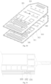
- the meanings of the attached markings are as follows: 1 box frame; 11 assembling surface; 12 connecting surface; 13 side beam profile; 131 first stepped surface; 132 second stepped surface; 133 third stepped surface; 14 intermediate beam structure; 2 liquid cooling plate layer; 3 bottom protection plate layer; 31 bottom protection plate body; 311 protruding step; 312 assembling step; 313 groove; 314 accommodating chamber; 32 protective coating; 321 gap; 4 buffer layer; 41 through-hole; 5 first edge sealing layer; 51 first sealing layer; 52 second sealing layer; 6 second edge sealing layer; 7 rivet nut; 8 bolt; 9 flow drilling screw; 10 reinforcing structure; 101 reinforcing rib; 102 assembly protruding step.
- the assembling surface of the side beam profile is provided with at least one descending stepped structure disposed from outer edges to inner edges, at least two first edge sealing layers are spaced apart along a descending direction of the stepped structure, and a thickness of the first edge sealing layer proximal to inner edges of the assembling surface is greater than that of the first edge sealing layer proximal to outer edges of the assembling surface.
- a buffer layer is provided between the bottom protection plate layer and the liquid cooling plate layer, which may increase the flexible buffering of the liquid cooling plate, and also forms a multi-layer sealing between the box frame, the bottom protection plate layer, and the liquid cooling plate layer, so as to improve the airtightness of the battery pack.
- the at least two first edge sealing layers between the box frame and the liquid cooling plate layer are set horizontally. Number of the sealing layers is increased, but the sealing thickness between the box frame and the liquid cooling plate layer is not increased, which therefore improves the sealing while also reduces the longitudinal space of the battery pack.
- the stepped structure includes a first stepped surface, a second stepped surface, and a third stepped surface arranged sequentially along the descending direction, and the first edge sealing layer is provided on at least one of the first stepped surface and the second stepped surface.
- the first edge sealing layer includes a first sealing layer, a side of the first sealing layer is configured to be abutted against the first stepped surface, and an opposite side of the first sealing layer is configured to be abutted against the liquid cooling plate layer.
- the first layer of sealing structure is achieved and good airtightness of the battery pack is ensured.
- the first edge sealing layer includes a second sealing layer, a side of the second sealing layer is configured to be abutted against the second stepped surface, and an opposite side of the second sealing layer is configured to be abutted against the liquid cooling plate layer.
- the second sealing layer may not only improve the airtightness, but also lead to an addition of the flexible buffering between the liquid cooling plate layer and the box frame.
- the bottom protection plate layer includes a bottom protection plate body and a protective coating, and the protective coating is assembled to a side of the bottom protection plate body distal to the box frame.
- the protective coating provides the following properties: such as waterproof, flame-retardant, mildew-resistant, cold resistant, corrosion-resistant, aging-resistant, UV-resistant, easy-to-clean, high-temperature-resistant, and good heat preservation, which may effectively protect the bottom protection plate, reduce potential damage to the battery caused by cuts and scraps on car chassis.
- edges of the bottom protection plate body are provided with a periphery of a protruding step protruding toward the box frame, a side of the second edge sealing layer is configured to be abutted against a surface of the protruding step, and an opposite side of the second edge sealing layer is configured to be abutted against the liquid cooling plate layer.
- the protruding steps are conducive to the assembly between the bottom protection plate layer and the liquid cooling plate layer, which achieves edge-to-edge fitting, and provides basis for sealing the edges.
- an inner side of the protruding step of the bottom protection plate body is formed with an accommodating chamber concave in a direction distal to the box frame, the buffer layer is positioned in the accommodating chamber, edges of an outer side of the protruding step are extended outwards to form a plurality of assembling steps and grooves connected alternately, main surfaces of the plurality of assembling steps are aligned with that of the protruding step, and main surfaces of the plurality of grooves are aligned with that of the bottom protection plate body on the inner side of the protruding step.
- the assembling step is assembled to the box frame, so that the buffer layer is pressed tightly to achieve the sealing and buffering.
- the accommodating chamber of the bottom protection plate body is provided with a reinforcing structure, and at least one of followings is met: the reinforcing structure is abutted against the buffer layer, and the reinforcing structure passes through the buffer layer to be in close proximity to the liquid cooling plate layer.
- the reinforcing structure may enhance the self strength of the bottom protection plate body, and/or, enhance the assembly strength between the bottom protection plate body, the liquid cooling plate layer, and the frame.
- a surface of the buffer layer proximal to the liquid cooling plate layer is protruded from a plane where the protruding step is positioned.
- the buffer layer achieves the buffering in a direction of its thickness.
- the protective coating is abutted against a surface of the bottom protection plate body distal to the box frame, and the protective coating is provided with a plurality of gaps corresponding to the plurality of assembling steps of the bottom protection plate body.
- the gaps may be designed in parts of the bottom protection plate that are not easily damaged to reduce the weight, lowering the overall weight of the battery pack and achieving the concept of lightweight.
- the assembling surface of the box frame is provided with a plurality of rivet nuts spaced apart, the bottom protection plate layer is attached to the rivet nuts by bolts, the liquid cooling plate layer is provided with allowance holes for avoiding contacting the bolts, and the liquid cooling plate layer is connected to the box frame through flow drilling screws.
- a distance between two adjacent flow drilling screws for connecting the liquid cooling plate and the box frame is not greater than 85mm; a piercing thickness of the flow drilling screws between the liquid cooling plate layer and the box frame is not greater than 4.5mm; and a distance between two adjacent rivet nuts of the assembling surface is not greater than 85mm.
- the securing stability between the liquid cooling plate layer and the box frame is satisfied, the securing stability between the box frame and the bottom protection plate layer is also satisfied.
- the piercing thickness of the flow drilling screws between the liquid cooling plate layer and the box frame being not greater than 4.5mm may restrict the thickness and the height of the box frame, and the piercing of the flow drilling screws may achieve the flexible compression of the first edge sealing layer.
- Multiple layers of the first edge sealing layers are identical in height after compressed, which saves space in the height direction, so as to reduce the overall height of the battery pack.
- a multi-sealed composite box structure including a box frame 1, liquid cooling plate layer 2, a buffer layer 4, and a bottom protection plate layer 3 provided sequentially from top to bottom.
- At least two first edge sealing layers 5 are sealed between the box frame 1 and edges of the liquid cooling plate layer 2.
- At least one second edge sealing layers 6 are sealed between edges of the liquid cooling plate layer 2 and edges of the bottom protection plate layer 3.
- the box frame 1 has an assembling surface 11, the assembling surface 11 is provided with a plurality of rivet nuts 7 spaced apart, the bottom protection plate layer 3 is attached to the rivet nuts 7 by bolts 8, the liquid cooling plate layer 2 is provided with allowance holes for avoiding contacting the bolts 8, and the liquid cooling plate layer 2 is connected to the box frame 1 through flow drilling screws 9.
- a buffer layer 4 is provided between the bottom protection plate layer 3 and the liquid cooling plate layer 2, which may increase the flexible buffer of the liquid cooling plate, and allow a multi-sealing to be formed between the box frame 1, the bottom protection plate layer 3, and the liquid cooling plate 2, thereby increasing the airtight reliability of the battery pack.
- a height direction of the battery pack is set as the Z-axis, the battery pack is placed with the direction toward the front of the car as the X-axis, and a direction perpendicular to the X-axis as the Y-axis.
- the box frame 1 includes a frame body and an intermediate beam structure 14, the side beam body is made of several side beam profiles 13 spliced together from end to end.
- the splices between frame body and the intermediate beam structure 14, among the side beam profiles 13 include, but are not limited to, such as welding, bonding, or one-piece connection.
- the specific number of the intermediate beam structures 14 is not specifically limited.
- the intermediate beam structures 14 there are 2-4 pieces of the intermediate beam structures 14 provided along the Y-axis, and a micro-beam along the X-axis is provided between two intermediate beam structures positioned in the middle.
- a bottom surface of the side beam profiles 13, i.e., the assembling surface 11, is provided with a plurality of holes for threading the flow drilling screws and holes for threading the bolts 8, and the holes for threading the flow drilling screws are spaced apart from the holes for threading the bolts 8, so as to achieve the assembly connection of the box frame 1.
- the box frame 1 includes the assembling surface 11 on bottom and a connecting surface 12 on top, in which the assembling surface 11 is configured to be assembled with the liquid cooling plate layer 2 and the bottom protection plate layer 3, and the connecting surface 12 is configured to connect the cover structure of the battery pack.
- the assembling surface 11 of the side beam profiles 13 is provided with at least one descending stepped structure disposed from outer edges to inner edges, which is configured to horizontally provide with at least two first edge sealing layers 5 spaced apart, and a thickness of the first edge sealing layer 5 with the assembling surface 11 proximal to inner edges is greater than that of the first edge sealing layer 5 with the assembling surface 11 proximal to outer edges.
- At least two first edge sealing layers 5 are horizontally provided between the box frame 1 and the liquid cooling plate layer 2, which leads to an increase of the number of sealing, but without an increase of the sealing thickness between the box frame 1 and the liquid cooling plate layer 2, thereby improving the sealing and lowering the longitudinal space of the battery pack along the Z-axis.
- Each of the stepped structure includes a first stepped surface 131, a second stepped surface 132, and a third stepped surface 133 arranged sequentially along the descending direction.
- the first edge sealing layer 5 is provided on the first stepped surface 131 and/or the second stepped surface 132, which may improve the connection airtightness between the liquid cooling plate layer 2 and the box frame 1.
- each side beam profile 13 provided along the Y-axis is provided with one stepped structure
- each side beam profile 13 provided along the X-axis is provided with two stepped structures.
- the stepped structure positioned on the outer side is configured to seal the first edge sealing layer 5, and the stepped structure positioned on the inner side is configured to secure and assemble with the bottom protection plate layer 3 and/or the liquid cooling plate layer 2.
- first edge sealing layers 5 there are two layers of the first edge sealing layers 5, which are the first sealing layer 51 and the second sealing layer 52.
- a side of the first sealing layer 51 is configured to be abutted against the first stepped surface 131, and an opposite side of the first sealing layer 51 is configured to be abutted against the liquid cooling plate layer 2, so as to form a first sealing ring structure.
- a side of the second sealing layer 52 is configured to be abutted against the second stepped surface 132, and an opposite side of the second sealing layer 52 is configured to be abutted against the liquid cooling plate layer 2, so as to form a second sealing ring structure.
- Edges of the bottom protection plate body 3 are provided with a periphery of a protruding step 311 protruding toward the box frame 1, a side of the second edge sealing layer 6 is configured to be abutted against a surface of the protruding step 311, and an opposite side of the second edge sealing layer 6 is configured to be abutted against the liquid cooling plate layer 2, so as to form the third sealing ring structure.
- the first sealing ring structure may serve to seal the box frame 1 and the liquid cooling plate layer 2, and the first sealing ring structure itself has a small amount of deformability to achieve a first buffering effect.
- a thickness of the second sealing ring structure is greater than that of the first sealing ring structure, and the second sealing ring structure is protruding from the first stepped surface 131, which may form a pre-tension force when securing and connecting the box frame 1 and the liquid cooling plate layer 2 to further enhance the connection airtightness.
- the extruded second sealing ring structure itself still has a certain amount of deformability, so that a second buffering effect is also achieved.
- the third sealing ring structure serves to seal the bottom protection plate layer 3 and the liquid cooling plate layer 2, when the bolts 8 penetrate through the bottom protection plate layer 3 and the liquid cooling plate layer 2 to be secured with the rivet nuts 7 on the box frame 1, the third sealing ring structure may form a pre-tension force, which further improves the connection airtightness between the bottom protection plate layer 3 and the liquid cooling plate layer 2.
- the third sealing ring structure itself has a certain amount of deformability, so as to achieve the third buffering effect.
- first sealing ring structure, the second sealing ring structure, and the third sealing ring structure include, but are not limited to, such as sealing adhesive, silicone foam sealing ring, or structural adhesive.
- first sealing ring structure adopts a sealing adhesive to be applied to form a first sealing layer 51
- the second sealing ring structure and the third sealing ring structure adopt the silicone foam sealing ring, which may provide good cushioning and sealing performance.
- the first sealing ring structure and the second sealing ring structure are provided in a horizontal direction and spaced apart, so that the first sealing ring structure is not stacked with the second sealing ring structure. Therefore, no increase in total sealing thickness is expected, reducing the height of the battery pack in the Z-axis direction.
- the bottom protection plate layer 3 is designed as an integral connection or an integral assembly between the bottom protection plate body 31 and the protective coating 32, with the protective coating 32 being assembled on the bottom surface of the bottom protection plate.
- the protective coating 32 adopts a PVC coating structure
- the PVC coating structure is waterproof, flame retardant, mildew resistant, cold resistant, corrosion resistant, aging resistant, UV resistant, easy to clean, high temperature resistant, and has good heat preservation, which effectively protects the bottom protection plate layer 3 and reduces the damage to the battery caused by the cuts and scrapes of the automobile chassis, and also plays a role in waterproofing and mildew proofing when water enters into the automobile chassis.
- edges of the bottom protection plate body 31 are provided with a periphery of a protruding step 311 protruding toward the box frame 1, a side of the second edge sealing layer 6 is configured to be abutted against a surface of the protruding step 311, and an opposite side of the second edge sealing layer 6 is configured to be abutted against the liquid cooling plate layer 2.
- the protruding step 311 is conducive to the assembly between the bottom protection plate layer 3 and the liquid cooling plate layer 2, which achieves edge-to-edge fitting, also provides basis for the sealing of the edges.
- An inner side of the protruding step 311 of the bottom protection plate body 31 is formed with an accommodating chamber 314 which is concave in a direction distal to the box frame 1, the buffer layer 4 is positioned in the accommodating chamber 314, edges of an outer side of the protruding step 311 are extended outwards to form a plurality of assembling steps 312 and grooves 313 connected alternately, top surfaces of the plurality of assembling steps 312 are aligned with that of the protruding step 311, and bottom walls of an inner side of the plurality of grooves 313 are aligned with a top surface of the bottom protection plate body 31 on the inner side of the protruding step 311, so as to facilitate the assembly between the assembling step 312 and the box frame 1, and the buffer layer 4 is also pressed tightly to achieve the sealing and buffering.
- the accommodating chamber 314 of the bottom protection plate body 31 is provided with a reinforcing structure 10.
- the reinforcing structure 10 is abutted against the buffer layer 4, and/or, the reinforcing structure 10 passes through the buffer layer 4 and is abutted against the liquid cooling plate layer 2.
- the reinforcing structure 10 enhances the self strength of the bottom protection plate body 31, and/or, enhances the assembly strength between the bottom protection plate body 31, the liquid cooling plate layer 2, and the frame.
- the reinforcing structure 10 includes reinforcing ribs 101 and the assembly protruding steps 102, and the reinforcing ribs 101 are protruded upwards in the Z-axis direction, so as to reduce the thickness of the buffer layer 4, so that the upper surface thereof may satisfy to be higher than the protruding step 311.
- the reinforcing ribs 101 are not limited in structure and direction, as long as the reinforcing ribs 101 is able to smoothly support the buffer layer 4 on a plane.
- the assembly protruding steps 102 are also protruded upwards in the Z-axis direction, so as to get close to the intermediate beam structure 14 configured along the X-axis direction, so that screws may pass through the assembly protruding steps 102 to be secured and mounted to the rivet nuts 7 on a bottom of the intermediate beam structure 14.
- a height of the assembly protruding step 102 should be greater than or equal to a length of the bolt 8, so that a lower end of the bolt 8 may not be protruded from a bottom of the bottom protection plate body 31.
- the buffer layer 4 is provided with through-holes 41 for avoiding contacting the assembly protruding steps 102, as long as the assembly protruding steps 102 may not act on the buffer layer 4 when screws pass through the assembly protruding steps 102 to be secured and mounted to the rivet nuts 7 on a bottom of the intermediate beam structure 14.
- a shape of the assembly protruding step 102 is not specifically limited.
- the reinforcing rib 101 is a shape of bar
- the assembly protruding step 102 is a shape of truncated cone.
- the protective coating 32 in order to further reduce the weight of the battery pack, appropriate weight reduction may be made on the protective coating 32.
- the protective coating 32 is abutted against a surface of the bottom protection plate body 31 distal to the box frame 1, so as to protect the bottom surface of the bottom protection plate.
- the upwardly protruding parts of the bottom protection plate since the surfaces of the assembly protruding steps 102 and the assembling steps 312 are relatively far from other planes, the possibility occurring friction or collision is relatively low.
- the protective coating 32 is provided with gaps 321 where the assembling steps 312 and the assembly protruding steps 102 of the bottom protection plate body 31 are positioned, so as to reduce the area of the protective coating 32, which saves the raw materials and also reduces the weight, reducing the overall weight of the battery pack, achieving a lightweight concept.
- a distance between two adjacent flow drilling screws 9 and/or rivet nuts 7 should be further limited. Specifically, at least one of followings is met: a distance between two adjacent flow drilling screws 9 for connecting the liquid cooling plate 2 and the box frame 1 is not greater than 85mm; a piercing thickness of the flow drilling screws 9 between the liquid cooling plate layer 2 and the box frame 1 is not greater than 4.5mm; and a distance between two adjacent rivet nuts 7 of the assembling surface 2 is not greater than 85mm.
- the piercing thickness of the flow drilling screws 9 between the liquid cooling plate layer 2 and the box frame 1 being not greater than 4.5mm may restrict the thickness and height of the box frame 1, which achieves the spatial compression of the edge sealing layer 5 and the second edge sealing layer 6 in the Z-axis direction, so as to achieve the flexible connection and a reduction in space occupation.
- the distance between two adjacent rivet nuts 7 may be different, or partly identical, and the distance between two adjacent flow drilling screws 9 may be different, or partly identical, which should be designed based on the actual situation to achieve no interference between the rivet nuts 7 and the flow drilling screws 9.
- the present disclosure also relates to a battery pack, including a cover, a battery module, and a multi-sealed composite box structure.
- the cover is assembled to the connecting surface 12 of the box frame 1, the battery module is position-limited assembled in the box frame 1 below the cover, and a three-layer flexible sealing structure between the box frame 1, the bottom protection plate layer 3, and the liquid cooling plate layer 2 is able to be configured to improve the resistance of the cell in the battery module. It greatly improves the protection effect of the battery pack, provides good self-cushioning adjustment ability, further strengthens the anti-drop and anti-shock characteristics, and also has good sealing to increase the safety and reliability of the battery pack.
- the multi-sealed composite box structure provided in the present disclosure provides the technical effects as follows.
Landscapes
- Chemical & Material Sciences (AREA)
- Chemical Kinetics & Catalysis (AREA)
- Electrochemistry (AREA)
- General Chemical & Material Sciences (AREA)
- Engineering & Computer Science (AREA)
- Manufacturing & Machinery (AREA)
- Secondary Cells (AREA)
- Battery Mounting, Suspending (AREA)
Priority Applications (1)
| Application Number | Priority Date | Filing Date | Title |
|---|---|---|---|
| MA71710A MA71710A (fr) | 2023-12-08 | 2024-10-09 | Structure de boîte composite multi-scellée et bloc-batterie |
Applications Claiming Priority (2)
| Application Number | Priority Date | Filing Date | Title |
|---|---|---|---|
| CN202323353671.XU CN221812116U (zh) | 2023-12-08 | 2023-12-08 | 一种多重密封的复合箱体结构及电池包 |
| CN202311685082.3A CN117691277A (zh) | 2023-12-08 | 2023-12-08 | 一种多重密封的复合箱体结构及电池包 |
Publications (1)
| Publication Number | Publication Date |
|---|---|
| EP4567967A1 true EP4567967A1 (de) | 2025-06-11 |
Family
ID=93061618
Family Applications (1)
| Application Number | Title | Priority Date | Filing Date |
|---|---|---|---|
| EP24205608.3A Pending EP4567967A1 (de) | 2023-12-08 | 2024-10-09 | Mehrfach versiegelte verbundkastenstruktur und batteriepack |
Country Status (4)
| Country | Link |
|---|---|
| US (1) | US20250192273A1 (de) |
| EP (1) | EP4567967A1 (de) |
| MA (1) | MA71710A (de) |
| WO (1) | WO2025118438A1 (de) |
Citations (3)
| Publication number | Priority date | Publication date | Assignee | Title |
|---|---|---|---|---|
| CN115020898B (zh) * | 2022-08-09 | 2022-11-04 | 楚能新能源股份有限公司 | 一种电池箱体 |
| US20230006277A1 (en) * | 2019-12-12 | 2023-01-05 | Valeo Systemes Thermiques | Compartment for an apparatus likely to emit heat |
| DE212021000535U1 (de) * | 2020-12-29 | 2023-09-28 | Svolt Energy Technology Company Limited | Batteriepackgehäuse und Batteriepack |
Family Cites Families (6)
| Publication number | Priority date | Publication date | Assignee | Title |
|---|---|---|---|---|
| CN216750099U (zh) * | 2022-02-11 | 2022-06-14 | 中创新航科技股份有限公司 | 电池箱 |
| KR20240119089A (ko) * | 2022-03-14 | 2024-08-06 | 비와이디 컴퍼니 리미티드 | 배터리 트레이, 배터리 팩 및 차량 |
| CN218274861U (zh) * | 2022-05-24 | 2023-01-10 | 北京车和家汽车科技有限公司 | 一种电池底护板结构、电池底部防护组件、电池及车辆 |
| CN218769729U (zh) * | 2022-08-22 | 2023-03-28 | 恒义超然工业技术(上海)有限公司 | 一种电池托盘箱体集成结构及电池模组 |
| CN220065947U (zh) * | 2023-06-19 | 2023-11-21 | 蜂巢能源科技股份有限公司 | 底护板组件和电池包 |
| CN117691277A (zh) * | 2023-12-08 | 2024-03-12 | 惠州亿纬锂能股份有限公司 | 一种多重密封的复合箱体结构及电池包 |
-
2024
- 2024-03-25 WO PCT/CN2024/083460 patent/WO2025118438A1/zh active Pending
- 2024-10-09 MA MA71710A patent/MA71710A/fr unknown
- 2024-10-09 EP EP24205608.3A patent/EP4567967A1/de active Pending
- 2024-10-11 US US18/914,046 patent/US20250192273A1/en active Pending
Patent Citations (3)
| Publication number | Priority date | Publication date | Assignee | Title |
|---|---|---|---|---|
| US20230006277A1 (en) * | 2019-12-12 | 2023-01-05 | Valeo Systemes Thermiques | Compartment for an apparatus likely to emit heat |
| DE212021000535U1 (de) * | 2020-12-29 | 2023-09-28 | Svolt Energy Technology Company Limited | Batteriepackgehäuse und Batteriepack |
| CN115020898B (zh) * | 2022-08-09 | 2022-11-04 | 楚能新能源股份有限公司 | 一种电池箱体 |
Also Published As
| Publication number | Publication date |
|---|---|
| US20250192273A1 (en) | 2025-06-12 |
| MA71710A (fr) | 2025-05-30 |
| WO2025118438A1 (zh) | 2025-06-12 |
Similar Documents
| Publication | Publication Date | Title |
|---|---|---|
| CN117691277A (zh) | 一种多重密封的复合箱体结构及电池包 | |
| EP4056408A1 (de) | Batteriepack und elektrisches fahrzeug | |
| US11139527B2 (en) | Lower box body and battery box | |
| CN217374126U (zh) | 电池包安装结构、车辆 | |
| US11766926B2 (en) | Battery pack case, battery pack including the same and vehicle including battery pack | |
| CN216720142U (zh) | 电池包框架、电池包和车辆 | |
| CN112582743B (zh) | 托盘、电池包及车辆 | |
| CN220290951U (zh) | 电池包箱体组件、电池包及车辆 | |
| EP4567967A1 (de) | Mehrfach versiegelte verbundkastenstruktur und batteriepack | |
| JP2025124751A (ja) | 蓄電装置 | |
| CN114447498A (zh) | 电池包和具有其的车辆 | |
| CN211907530U (zh) | 一种电池包防护板、电池包模组及车辆 | |
| CN219832926U (zh) | 电池箱及电池包 | |
| CN221812116U (zh) | 一种多重密封的复合箱体结构及电池包 | |
| CN218867288U (zh) | 一种隔离板及电池框架 | |
| CN217730588U (zh) | 一种挤压铝顶盖前横梁与侧围外板总成的连接结构 | |
| JP7386678B2 (ja) | 電池保護構造体 | |
| CN208868157U (zh) | 门槛梁及汽车 | |
| CN120728137A (zh) | 一种集成式下箱体总成结构、电池包及车辆 | |
| CN223245793U (zh) | 一种动力电池箱及动力电池箱的下箱体 | |
| CN222126783U (zh) | 一种电池包结构 | |
| CN213810889U (zh) | 室外机的底盘结构、室外机及空调 | |
| CN219321544U (zh) | 一种电池下箱体 | |
| CN223850416U (zh) | 一种蒙皮式电池托盘 | |
| CN222214382U (zh) | 电池包的壳体、电池包以及车辆 |
Legal Events
| Date | Code | Title | Description |
|---|---|---|---|
| PUAI | Public reference made under article 153(3) epc to a published international application that has entered the european phase |
Free format text: ORIGINAL CODE: 0009012 |
|
| STAA | Information on the status of an ep patent application or granted ep patent |
Free format text: STATUS: REQUEST FOR EXAMINATION WAS MADE |
|
| 17P | Request for examination filed |
Effective date: 20241009 |
|
| AK | Designated contracting states |
Kind code of ref document: A1 Designated state(s): AL AT BE BG CH CY CZ DE DK EE ES FI FR GB GR HR HU IE IS IT LI LT LU LV MC ME MK MT NL NO PL PT RO RS SE SI SK SM TR |