EP4567923A1 - Positivelektrodenaktivmaterial, positivelektrodenfolie, sekundärbatterie und elektrische vorrichtung - Google Patents
Positivelektrodenaktivmaterial, positivelektrodenfolie, sekundärbatterie und elektrische vorrichtung Download PDFInfo
- Publication number
- EP4567923A1 EP4567923A1 EP23916720.8A EP23916720A EP4567923A1 EP 4567923 A1 EP4567923 A1 EP 4567923A1 EP 23916720 A EP23916720 A EP 23916720A EP 4567923 A1 EP4567923 A1 EP 4567923A1
- Authority
- EP
- European Patent Office
- Prior art keywords
- lithium
- transition metal
- metal oxide
- nickel transition
- active material
- Prior art date
- Legal status (The legal status is an assumption and is not a legal conclusion. Google has not performed a legal analysis and makes no representation as to the accuracy of the status listed.)
- Pending
Links
Images


Classifications
-
- H—ELECTRICITY
- H01—ELECTRIC ELEMENTS
- H01M—PROCESSES OR MEANS, e.g. BATTERIES, FOR THE DIRECT CONVERSION OF CHEMICAL ENERGY INTO ELECTRICAL ENERGY
- H01M10/00—Secondary cells; Manufacture thereof
- H01M10/05—Accumulators with non-aqueous electrolyte
- H01M10/052—Li-accumulators
- H01M10/0525—Rocking-chair batteries, i.e. batteries with lithium insertion or intercalation in both electrodes; Lithium-ion batteries
-
- H—ELECTRICITY
- H01—ELECTRIC ELEMENTS
- H01M—PROCESSES OR MEANS, e.g. BATTERIES, FOR THE DIRECT CONVERSION OF CHEMICAL ENERGY INTO ELECTRICAL ENERGY
- H01M4/00—Electrodes
- H01M4/02—Electrodes composed of, or comprising, active material
- H01M4/36—Selection of substances as active materials, active masses, active liquids
- H01M4/362—Composites
- H01M4/364—Composites as mixtures
-
- H—ELECTRICITY
- H01—ELECTRIC ELEMENTS
- H01M—PROCESSES OR MEANS, e.g. BATTERIES, FOR THE DIRECT CONVERSION OF CHEMICAL ENERGY INTO ELECTRICAL ENERGY
- H01M4/00—Electrodes
- H01M4/02—Electrodes composed of, or comprising, active material
- H01M4/36—Selection of substances as active materials, active masses, active liquids
- H01M4/362—Composites
- H01M4/366—Composites as layered products
-
- H—ELECTRICITY
- H01—ELECTRIC ELEMENTS
- H01M—PROCESSES OR MEANS, e.g. BATTERIES, FOR THE DIRECT CONVERSION OF CHEMICAL ENERGY INTO ELECTRICAL ENERGY
- H01M4/00—Electrodes
- H01M4/02—Electrodes composed of, or comprising, active material
- H01M4/36—Selection of substances as active materials, active masses, active liquids
- H01M4/48—Selection of substances as active materials, active masses, active liquids of inorganic oxides or hydroxides
- H01M4/50—Selection of substances as active materials, active masses, active liquids of inorganic oxides or hydroxides of manganese
- H01M4/505—Selection of substances as active materials, active masses, active liquids of inorganic oxides or hydroxides of manganese of mixed oxides or hydroxides containing manganese for inserting or intercalating light metals, e.g. LiMn2O4 or LiMn2OxFy
-
- H—ELECTRICITY
- H01—ELECTRIC ELEMENTS
- H01M—PROCESSES OR MEANS, e.g. BATTERIES, FOR THE DIRECT CONVERSION OF CHEMICAL ENERGY INTO ELECTRICAL ENERGY
- H01M4/00—Electrodes
- H01M4/02—Electrodes composed of, or comprising, active material
- H01M4/36—Selection of substances as active materials, active masses, active liquids
- H01M4/48—Selection of substances as active materials, active masses, active liquids of inorganic oxides or hydroxides
- H01M4/52—Selection of substances as active materials, active masses, active liquids of inorganic oxides or hydroxides of nickel, cobalt or iron
- H01M4/525—Selection of substances as active materials, active masses, active liquids of inorganic oxides or hydroxides of nickel, cobalt or iron of mixed oxides or hydroxides containing iron, cobalt or nickel for inserting or intercalating light metals, e.g. LiNiO2, LiCoO2 or LiCoOxFy
-
- H—ELECTRICITY
- H01—ELECTRIC ELEMENTS
- H01M—PROCESSES OR MEANS, e.g. BATTERIES, FOR THE DIRECT CONVERSION OF CHEMICAL ENERGY INTO ELECTRICAL ENERGY
- H01M4/00—Electrodes
- H01M4/02—Electrodes composed of, or comprising, active material
- H01M2004/021—Physical characteristics, e.g. porosity, surface area
-
- Y—GENERAL TAGGING OF NEW TECHNOLOGICAL DEVELOPMENTS; GENERAL TAGGING OF CROSS-SECTIONAL TECHNOLOGIES SPANNING OVER SEVERAL SECTIONS OF THE IPC; TECHNICAL SUBJECTS COVERED BY FORMER USPC CROSS-REFERENCE ART COLLECTIONS [XRACs] AND DIGESTS
- Y02—TECHNOLOGIES OR APPLICATIONS FOR MITIGATION OR ADAPTATION AGAINST CLIMATE CHANGE
- Y02E—REDUCTION OF GREENHOUSE GAS [GHG] EMISSIONS, RELATED TO ENERGY GENERATION, TRANSMISSION OR DISTRIBUTION
- Y02E60/00—Enabling technologies; Technologies with a potential or indirect contribution to GHG emissions mitigation
- Y02E60/10—Energy storage using batteries
Definitions
- This application relates to the technical field of batteries, and in particular, to a positive active material, a positive electrode plate, a secondary battery, and an electrical device.
- Lithium-ion batteries as electrochemical energy storage devices, are favored by the energy storage and power battery industries due to their large capacity, no memory effect and wide application window.
- the pursuit of battery life and lifespan has become increasingly a pain point and consensus in the industry.
- Ternary materials have attracted widespread attention due to their low cost and high capacity.
- increasing their working voltage is the most effective way.
- the lifespan of ternary materials decreases significantly under high voltage conditions, especially under high temperature conditions. Therefore, improving the energy density of ternary materials while ensuring their service life has become an industry challenge.
- This application provides a positive active material, a positive electrode plate, a secondary battery, and an electrical device to improve the energy density and cycle life of the positive active material.
- a first aspect of this application provides a positive active material which includes a first lithium-nickel transition metal oxide and a second lithium-nickel transition metal oxide.
- Both the first lithium-nickel transition metal oxide and the second lithium-nickel transition metal oxide contain zirconium, and a molar content of zirconium element in the first lithium-nickel transition metal oxide is less than a molar content of zirconium element in the second lithium-nickel transition metal oxide, the first lithium-nickel transition metal oxide is of one or more structures of a monocrystalline particle or a quasi-monocrystalline particle, and the second lithium-nickel transition metal oxide is a secondary particle formed by aggregation of a plurality of primary particles.
- the first lithium-nickel transition metal oxide is of one or more structures of a monocrystallinel or a quasi-monocrystalline, and the structures are stable, strong, and not easily cracked in the cycle process, especially with better cycle performance at high temperature;
- the second lithium-nickel transition metal oxide is a secondary particle formed by the aggregation of the plurality of primary particles, and lithium ions diffuse more easily in this material, so that the discharge specific capacity is larger than that of a single crystal or a quasi-single crystal structure with an equal particle diameter, and the rate performance is better.
- the first lithium-nickel transition metal oxide and the second lithium-nickel transition metal oxide contain zirconium element to further improve the particle strength of the oxides.
- the enhancement of the particle strength can greatly improve the cracking resistance of the positive electrode material in the cycle process, especially by controlling the molar content of zirconium element in the first lithium-nickel transition metal oxide to be less than the molar content of zirconium element in the second lithium-nickel transition metal oxide, reducing the strength difference between the two oxides, better improving the cycle life of a battery cell as a whole, increasing the depth of charging and discharging, and increasing the mass energy density.
- a ratio of the molar content of zirconium element in the above first lithium-nickel transition metal oxide to the molar content of zirconium element in the second lithium-nickel transition metal oxide is d, and 0.5 ⁇ d ⁇ 1, optionally 0.7 ⁇ d ⁇ 1, and further optionally 0.8 ⁇ d ⁇ 0.9.
- particle strength of the above first lithium-nickel transition metal oxide is greater than particle strength of the second lithium-nickel transition metal oxide.
- the particle strength of the first lithium-nickel transition metal oxide is 30 MPa-300 MPa, and further optionally 110 MPa-230 MPa.
- the particle strength of the second lithium-nickel transition metal oxide is 20 MPa-250 MPa, and further optionally 90 MPa-210 MPa.
- a difference between the particle strength of the first lithium-nickel transition metal oxide and the particle strength of the second lithium-nickel transition metal oxide is between 10 MPa and 50 MPa, and further optionally between 20 MPa and 30 MPa.
- a number of the monocrystalline particle contained by the quasi-monocrystalline particle of the above first lithium-nickel transition metal oxide in a Scanning Electron Microscope (SEM) image is ⁇ 5/ ⁇ m 2 .
- a number of the primary particles contained by the secondary particle of the second lithium-nickel transition metal oxide in an SEM image is 3/ ⁇ m 2 -30/ ⁇ m 2 .
- a volume particle diameter distribution curve of the positive active material is a bimodal curve
- a low peak particle diameter of the bimodal curve is a first peak particle diameter
- a high peak particle diameter is a second peak particle diameter
- the first peak particle diameter is 2 ⁇ m-6 ⁇ m
- the second peak particle diameter is 6 ⁇ m-15 ⁇ m.
- Optimization of material particle gradation may effectively improve the voltage window and compaction density of the material.
- a high voltage window and compaction density are beneficial to achieving a high volumetric energy density and mass density, thereby significantly improving the endurance of the secondary battery.
- peak separation fitting is performed on the bimodal curve to obtain a small particle fitted peak pattern and a large particle fitted peak pattern
- the above D V N is measured using a laser particle diameter analyzer.
- the particle diameter of the positive active material is graded in the above manner, and the interparticle filling property is improved, thereby further improving the compaction
- a volume particle diameter distribution of the first lithium-nickel transition metal oxide satisfies a small particle fitted peak pattern; and a volume particle diameter distribution of the second lithium-nickel transition metal oxide satisfies the large particle fitted peak pattern.
- the first lithium-nickel transition metal oxide and the second lithium-nickel transition metal oxide simultaneously realize a better matching relationship in two aspects of composition and particle diameter, which further enhances the compaction density and improves the cyclic cracking defect.
- a molar amount of Zr in R per mole of the first lithium-nickel transition metal oxide or the second lithium-nickel transition metal oxide is less than or equal to 0.15, and further optionally, the molar amount of Zr in R per mole of the first lithium-nickel transition metal oxide or the second lithium-nickel transition metal oxide is less than or equal to 0.11.
- a Ni element content in the first lithium-nickel transition metal oxide is 0.5 ⁇ x ⁇ 0.98, and the Ni element content in the second lithium-nickel transition metal oxide is 0.6 ⁇ x ⁇ 0.98.
- the lithium-nickel transition metal oxide with high nickel or low and medium nickel may further improve the power performance of the oxide or enhance the structural stability of the oxide by further doping M and/or R elements.
- a molar amount of Zr in R per mole of the first lithium-nickel transition metal oxide or the second lithium-nickel transition metal oxide is less than or equal to 0.15.
- a Ni element content in the first lithium-nickel transition metal oxide is 0.5 ⁇ x ⁇ 0.98
- the Ni element content in the second lithium-nickel transition metal oxide is 0.6 ⁇ x ⁇ 0.98.
- the above cladding layer includes one oxide cladding layer or two oxide cladding layers, and/or an inner layer of the two oxide cladding layers is an island-shaped oxide cladding layer, and an outer layer of the two oxide cladding layers is a layered oxide cladding layer
- Interface performance is a key indicator for improving the performance of the positive electrode material. By adopting different forms of coating structures, the capacity may be increased while reducing side effects with the electrolyte solution, achieving a win-win goal.
- a thickness of the above cladding layer is 0.1 nm-200 nm, optionally 0.1 nm-100 nm, and further optionally 0.1 nm-50 nm, thereby avoiding obvious hindrance to ion diffusion caused by the excessive thickness of the cladding layer
- an element of the oxide cladding layer includes one or more of a group consisting of Zr, Al, P, B, Ti, W, Co, Nb, Mo, and Mg. The oxide cladding layer having the above elements improves the interface stability of the positive active material/electrolyte solution, and further enhances the cyclicity and safety.
- a weight ratio of the first lithium-nickel transition metal oxide in the above positive active material is 10%-95%, and optionally 50%-90%.
- a second aspect of this application provides a positive electrode plate including a current collector and a positive film layer, where the positive film layer includes a positive active material, and the positive active material is any one of the above positive active materials.
- the positive active material of this application has a good structure and good interface stability, so the positive electrode-electrolyte solution interface effect is low, which reduces the cracking of the positive active material, and meanwhile, reduces the side reaction between the positive electrode and the electrolyte solution, and reduces the formation of interface micro-cracks, thereby improving the energy density and lifespan of the positive electrode plate.
- a third aspect of this application provides a secondary battery including a positive electrode plate, a negative electrode plate, a separator, and an electrolyte solution, where the positive electrode plate is the above positive electrode plate.
- the secondary battery of this application has the advantages of a high energy density and high cycle performance.
- a fourth aspect of this application provides an electrical device including a secondary battery, where the secondary battery is selected from the above secondary batteries.
- the electrical device of this application operates more stably and safely at high temperature.
- Range disclosed in this application is limited in the form of lower limit and upper limit, and the given range is limited by selecting a lower limit and an upper limit, and the selected lower limit and upper limit define the boundary of a special range.
- the range limited in this way may include end values or not include end values, and may be combined arbitrarily, that is, any lower limit may be combined with any upper limit to form a range. For example, if the range of 60 to 120 and 80 to 110 is listed for a particular parameter, it is understood that the range of 60 to 110 and 80 to 120 is also expected.
- the numerical range "a to b" represents the abbreviation of any real number combination between a and b, where a and b are all real numbers.
- the numerical range "0 to 5" means that all real numbers between "0 to 5" are listed in this application and "0 to 5" is just an abbreviation of these numerical combinations.
- a parameter is expressed as an integer ⁇ 2, it is equivalent to disclosing that the parameter is, for example, an integer 2, 3, 4, 5, 6, 7, 8, 9, 10, 11, 12, etc.
- any embodiments and optional embodiments hereof may be combined with each other to form a new technical solution.
- any technical features and optional technical features hereof may be combined with each other to form a new technical solution.
- the method includes steps (a) and (b), indicating that the method may include steps (a) and (b) performed sequentially, or may include steps (b) and (a) performed sequentially.
- the method may further include step (c), indicating that step (c) may be added to the method in any order, for example, the method may include steps (a), (b) and (c), or may include steps (a), (c) and (b), or may include steps (c), (a) and (b), etc.
- the term "or” used herein is inclusive.
- the phrase "A or B” means "A alone, B alone, or both A and B". More specifically, all and any of the following conditions satisfy the condition "A or B”: A is true (or existent) and B is false (or absent); A is false (or absent) and B is true (or existent); and, both A and B are true (or existent).
- a secondary battery also known as a rechargeable battery or storage battery, is a battery that is reusable after an active material in the battery is activated by charging the battery that has been discharged.
- the secondary battery includes a positive electrode plate, a negative electrode plate, a separator, and an electrolyte solution.
- active ions e.g. lithium ions
- the separator is disposed between the positive electrode plate and the negative electrode plate, which mainly plays the role of preventing short circuits between the positive and negative electrodes, and at the same time, may allow active ions to pass through.
- the electrolyte solution mainly plays the role of conducting active ions between the positive electrode plate and the negative electrode plate.
- One embodiment of this application provides a positive active material which includes a first lithium-nickel transition metal oxide and a second lithium-nickel transition metal oxide.
- Both the first lithium-nickel transition metal oxide and the second lithium-nickel transition metal oxide contain zirconium, and a molar content of zirconium element in the first lithium-nickel transition metal oxide is less than a molar content of zirconium element in the second lithium-nickel transition metal oxide, the first lithium-nickel transition metal oxide is of one or more structures of a monocrystalline particle or a quasi-monocrystalline particle, and the second lithium-nickel transition metal oxide is a secondary particle formed by aggregation of a plurality of primary particles.
- ternary positive electrode materials may experience material cracking, especially under high cut-off voltage conditions.
- the internal resistance of the battery cell and the gas production of the battery cell will increase significantly, accelerating the capacity decay of the battery cell in the cycle process.
- the expansion force of the battery cell will rise, thus leading to safety accidents of the battery cell. Therefore, reducing the cracking of the positive electrode material in the cycle process is the fundamental reason for solving the above phenomenon.
- the structural stability of the materials may be enhanced, and the phenomenon of cyclic cracking may be improved.
- the combination of monocrystalline and polycrystalline may not only obtain a higher compaction density, but also improve the serious cracking of poly-crystals in the materials under a high voltage and prolong the lifespan of the battery cell.
- the first lithium-nickel transition metal oxide is of one or more structures of a monocrystalline particle or a quasi-monocrystalline particle, and the structures are stable, strong, and not easily cracked in the cycle process, especially with better cycle performance at high temperature;
- the second lithium-nickel transition metal oxide is a secondary particle formed by the aggregation of the plurality of primary particles, and lithium ions diffuse more easily in this material, so that the discharge specific capacity is larger than that of a monocrystalline or a quasi-monocrystalline structure with an equal particle diameter, and the rate performance is better.
- the particle strength of the oxides is further improved, and especially by doping more zirconium element in the second lithium-nickel transition metal oxide, the particle strength of the second lithium-nickel transition metal oxide is more effectively improved, cracking of the secondary particle is effectively reduced, and the difference in strength between the two oxides is reduced, so that the cycle life of the battery cell is better improved in cooperation with the first lithium-nickel transition metal oxide; and at the same time, the use of zirconium element may increase the charging and discharging depth of the positive active material and increase the mass energy density.
- Monocrystalline particle it refers to a complete particle that is not an aggregate of primary particles. Generally, in this application, the size of the monocrystalline particle is micron-sized.
- Quasi-monocrystalline particle it refers to a particle formed by aggregation of 2 to 10 monocrystalline particles.
- the number of monocrystalline particles is small and the size is between several hundred nanometers and 2 ⁇ m to 5 ⁇ m.
- Secondary particle it is an aggregate formed by aggregation of a plurality of primary particles.
- the "plurality of” herein generally refers to 10 or more.
- the zirconium content ratio of the above first lithium-nickel transition metal oxide to the second lithium-nickel transition metal oxide is d, and 0.5 ⁇ d ⁇ 1, optionally 0.7 ⁇ d ⁇ 1, and further optionally 0.8 ⁇ d ⁇ 0.9.
- the above d may be any point value in a range constituted by any two points of 0.51, 0.55, 0.6, 0.65, 0.7, 0.75, 0.8, 0.85, 0.9, or 0.98.
- doping zirconium element can effectively increase the particle strength of the material.
- increasing the doping amount of zirconium element will significantly reduce the capacity of the positive electrode material. Therefore, the relationship between the capacity of the positive electrode material and the particle strength is balanced by optimizing the amount of zirconium element.
- the doping amount of zirconium element in the above mixture can be measured by inductively coupled plasma emission spectrometry, and the ratio of zirconium element in the first lithium-nickel transition metal oxide and the second lithium-nickel transition metal oxide is determined by respectively measuring the ratio of zirconium element in the two lithium-nickel transition metal oxides.
- the particle strength of the above first lithium-nickel transition metal oxide is greater than the particle strength of the second lithium-nickel transition metal oxide.
- the particle strength of the first lithium-nickel transition metal oxide is 30 MPa to 300 MPa.
- it may be any point value in a range constituted by any two points of 30 MPa, 50 MPa, 80 MPa, 100 MPa, 110 MPa, 120 MPa, 150 MPa, 200 MPa, 230 MPa, 250 MPa, or 300 MPa, and may be further optionally 110 MPa-230 MPa.
- the particle strength of the second lithium-nickel transition metal oxide is 20 MPa to 250 MPa.
- it is any point value in a range constituted by any two points of 20 MPa, 50 MPa, 70 MPa, 90 MPa, 120 MPa, 150 MPa, 180 MPa, 200 MPa, 210 MPa, or 250 MPa, and further optionally 90 MPa to 210 MPa.
- the respective particle strength is improved, thus further reducing the formation of interface cracks in the positive active material in the cycle process, improving cycle stability, and prolonging the lifespan of the positive active material.
- the difference between the particle strength of the above first lithium-nickel transition metal oxide and the particle strength of the second lithium-nickel transition metal oxide is between 10 MPa and 50 MPa, and further optionally between 20 MPa and 30 MPa.
- the strength matching of the two particles is improved, excessive extrusion stress between the two particles is avoided due to the excessive strength difference between the two particles, and thus the cracking of the two particles caused by extrusion is effectively controlled.
- the above particle strength can be measured by a dynamic ultra-micro hardness tester (Shimadzu DUH-211S).
- the particle strength of the material is tested using a 115° triangular cone probe and under a pressure of 0 mN to 20 mN, and the force value and pressure when the material is broken are recorded.
- the number of the monocrystalline particles contained in the quasi-monocrystalline particle of the above first lithium-nickel transition metal oxide in an SEM image is ⁇ 5/ ⁇ m 2 , e.g. 1, 2, 3, 4, or 5.
- the number of the primary particles contained in the secondary particle of the above second lithium-nickel transition metal oxide in an SEM image is 3/ ⁇ m 2 -30/ ⁇ m 2 , e.g. 3, 5, 8, 10, 12, 15, 20, 25, or 30.
- Monocrystalline particles are usually prone to aggregation due to high sintering temperature and a small particle diameter, forming quasi-monocrystalline particles.
- a volume particle diameter distribution curve of the positive active material is a bimodal curve
- a low peak particle diameter of the bimodal curve is a first peak particle diameter
- a high peak particle diameter is a second peak particle diameter
- the first peak particle diameter is 2 ⁇ m to 6 ⁇ m
- the second peak particle diameter is 6 ⁇ m to 15 ⁇ m.
- a high voltage window and compaction density are beneficial to achieving a high volumetric energy density and mass density, thereby significantly improving the endurance of the secondary battery.
- peak separation fitting is performed on the bimodal curve to obtain a small particle fitted peak pattern and a large particle fitted peak pattern
- the above D V N is measured using a laser particle diameter analyzer.
- the particle diameter of the positive active material is graded in the above manner, and the interparticle filling property is improved, thereby further improving the compaction density of the
- a volume particle diameter distribution of the first lithium-nickel transition metal oxide satisfies a small particle fitted peak pattern; and a volume particle diameter distribution of the second lithium-nickel transition metal oxide satisfies the large particle fitted peak pattern.
- the first lithium-nickel transition metal oxide and the second lithium-nickel transition metal oxide simultaneously realize a better matching relationship in two aspects of composition and particle diameter, which further enhances the compaction density and improves the cyclic cracking defect.
- the first lithium-nickel transition metal oxide and the second lithium-nickel transition metal oxide of this application may be high-nickel or low-nickel lithium-nickel transition metal oxides commonly used in the art for positive electrode materials.
- a molar amount of Zr in R per mole of the first lithium-nickel transition metal oxide or the second lithium-nickel transition metal oxide is less than or equal to 0.15; and further optionally, the molar amount of Zr in R per mole of the first lithium-nickel transition metal oxide or the second lithium-nickel transition metal oxide is less than or equal to 0.11.
- a Ni element content in the first lithium-nickel transition metal oxide is 0.5 ⁇ x ⁇ 0.98
- a Ni element content in the second lithium-nickel transition metal oxide is 0.6 ⁇ x ⁇ 0.98.
- the high-nickel or low-and-medium-nickel lithium-nickel transition metal oxide may further improve the power performance of the oxide or enhance the structural stability of the oxide by further doping M and R elements.
- Zr exists in the first lithium-nickel transition metal oxide and the second lithium-nickel transition metal oxide in a doped manner, which may obviously improve the structural stability of the material.
- a molar amount of Zr in R per mole of the first lithium-nickel transition metal oxide or the second lithium-nickel transition metal oxide is less than or equal to 0.15.
- a Ni element content in the first lithium-nickel transition metal oxide is 0.5 ⁇ x ⁇ 0.98
- the Ni element content in the second lithium-nickel transition metal oxide is 0.6 ⁇ x ⁇ 0.98.
- the above cladding layer includes one oxide cladding layer or two oxide cladding layers; and further optionally, an inner layer of the two oxide cladding layers is an island-shaped oxide cladding layer, and an outer layer of the two oxide cladding layers is a layered oxide cladding layer.
- Island-shaped oxide cladding layer a cladding layer formed by the oxide in discrete island-shaped morphology
- Layered oxide cladding layer a cladding layer formed by the oxide in continuous layered morphology.
- the layered shape may be a layered structure with a uniform thickness or a layered structure with a non-uniform thickness. As long as it is a continuous oxide film layer, it is a layered oxide cladding layer.
- the island-shaped oxide cladding layer may avoid the problem of decreased material conductivity caused by thick layered coating. Further setting a layered oxide cladding layer outside the island-shaped oxide cladding layer is more effective in improving the cycle performance of the material. By adopting different forms of coating structures, the capacity may be increased while reducing side effects with the electrolyte solution, achieving a win-win goal.
- a thickness of the cladding layer is controlled to be 0.1 nm to 200 nm, optionally 0.1 nm to 100 nm, and further optionally 0.1 nm to 50 nm, thereby avoiding obvious hindrance to ion diffusion caused by the excessive thickness of the cladding layer and thus a decrease in ionic conductivity, where the thickness of the cladding layer is measured using a transmission electron microscope.
- an element of the oxide cladding layer includes one or more of Zr, Al, P, B, Ti, W, Co, Nb, Mo, and Mg.
- the oxide cladding layer having the above elements improves the interface stability of the positive active material/electrolyte solution, and further enhances the cyclicity and safety.
- the weight ratio of the first lithium-nickel transition metal oxide by adjusting a weight ratio of the first lithium-nickel transition metal oxide, the overall structural stability and energy density of the positive active material are adjusted, and the weight content of the first lithium-nickel transition metal oxide in the above positive active material is 10% to 90%.
- the weight ratio of the first lithium-nickel transition metal oxide in the positive active material is optionally 50% to 90%.
- the following method may be referred to: If the Ni/Co/Mn components of the first lithium-nickel transition metal oxide and the second lithium-nickel transition metal oxide are different, the total proportion of Ni, Co and Mn in the positive active material in the positive electrode plate may be tested by Inductive Coupled Plasma Emission Spectrometer (ICP) first, and then the respective proportions of Ni, Co and Mn of the two morphological particles are tested by combining Energy Dispersive X-Ray Spectroscopy (EDX) separately. Based on the above detection results of ICP and EDX, it is assumed that the mass ratio of the first material is x and the other one is (1-x), and the respective mass ratios of the two materials may be obtained by putting them into the equation.
- ICP Inductive Coupled Plasma Emission Spectrometer
- EDX Energy Dispersive X-Ray Spectroscopy
- the positive active material is sieved through screens with different meshes to obtain active materials with different particle diameters respectively, and the proportions and contents of the first lithium-nickel transition metal oxide and the second lithium-nickel transition metal oxide materials are determined according to the ICP measured data.
- the positive active material of this application may be prepared by referring to conventional methods after formulation according to the composition of this application.
- the following steps can be adopted for preparation: mixing lithium hydroxide or lithium carbonate, nickel cobalt M precursor material Ni x Co y M 1-x-y (OH) 2 , and N additive, sintering under the presence of oxygen, controlling the sintering conditions to obtain the first lithium-nickel transition metal oxide and the second lithium-nickel transition metal oxide respectively, and mixing the first lithium-nickel transition metal oxide and the second lithium-nickel transition metal oxide according to a preset mass ratio to prepare the positive active material.
- lithium-nickel transition metal oxide island-shaped coating and layered coating are achieved by controlling coating elements and coating temperature.
- aluminum element usually forms an island-shaped coating on the surface at 300 °C to 400 °C, while boron element is more likely to form a layered coating on the surface.
- specific coating means reference may be made to the prior art, and this application will not make a repeated description.
- a positive electrode plate generally includes a positive current collector and a positive film layer that overlays at least one surface of the positive current collector.
- the positive film layer includes a positive active material.
- the positive current collector includes two surfaces opposite to each other in a thickness direction of the positive current collector.
- the positive electrode film layer is disposed on either or both of the two opposite surfaces of the positive current collector.
- the positive current collector may be metal foil or a composite current collector.
- the metal foil aluminum foil may be used.
- the composite current collector may include a polymer material base layer and a metal layer formed on at least one surface of the polymer material base layer.
- the composite current collector may be formed by forming a metal material (aluminum, aluminum alloy, nickel, nickel alloy, titanium, titanium alloy, silver and silver alloy, etc.) on a polymer material substrate (such as a substrate of polypropylene (PP), polyethylene terephthalate (PET), polybutylene terephthalate (PBT), polystyrene (PS), polyethylene (PE), etc.).
- PP polypropylene
- PET polyethylene terephthalate
- PBT polybutylene terephthalate
- PS polystyrene
- PE polyethylene
- the positive active material is any one of the positive active materials provided in this application.
- the positive active material of this application has a good structure and good interface stability, so the positive electrode-electrolyte solution interface effect is low, which reduces the cracking of the positive active material, and meanwhile, reduces the side reaction between the positive electrode and the electrolyte solution, and reduces the formation of interface micro-cracks, thereby improving the energy density and lifespan of the positive electrode plate.
- the positive film layer further optionally includes a binder.
- the binder may include at least one of polyvinylidene fluoride (PVDF), polytetrafluoroethylene (PTFE), a vinylidene fluoride-tetrafluoroethylene-propylene terpolymer, a vinylidene fluoride-hexafluoropropylene-tetrafluoroethylene terpolymer, a tetrafluoroethylene-hexafluoropropylene copolymer, and fluorine-containing acrylate resin.
- PVDF polyvinylidene fluoride
- PTFE polytetrafluoroethylene
- PTFE polytetrafluoroethylene
- the positive film layer further optionally includes a conductive agent.
- the conductive agent may include at least one of superconductive carbon, acetylene black, carbon black, Ketjen black, a carbon dot, a carbon nanotube, graphene, and a carbon nanofiber.
- the positive electrode plate may be prepared according to the following method: dispersing the ingredients of the positive electrode plate such as the positive active material, the conductive agent, the binder, and any other ingredients into a solvent (such as N-methyl-pyrrolidone) to form a positive electrode slurry, coating a positive current collector with the positive electrode slurry, and performing steps such as drying and cold pressing to obtain the positive electrode plate.
- a solvent such as N-methyl-pyrrolidone
- the negative electrode plate includes a negative current collector and a negative electrode film layer disposed on at least one surface of the negative current collector.
- the negative electrode film layer includes a negative active material.
- the negative current collector includes two surfaces opposite to each other in a thickness direction of the negative current collector.
- the negative electrode film layer is disposed on either or both of the two opposite surfaces of the negative current collector.
- the negative current collector may be metal foil or a composite current collector.
- the metal foil copper foil may be used.
- the composite current collector may include a polymer material base layer and a metal layer formed on at least one surface of the polymer material substrate.
- the composite current collector may be formed by forming a metal material (copper, copper alloy, nickel, nickel alloy, titanium, titanium alloy, silver and silver alloy, etc.) on a polymer material substrate (such as a substrate of polypropylene (PP), polyethylene terephthalate (PET), polybutylene terephthalate (PBT), polystyrene (PS), polyethylene (PE), etc.).
- PP polypropylene
- PET polyethylene terephthalate
- PBT polybutylene terephthalate
- PS polystyrene
- PE polyethylene
- the negative active material may be a negative active material known for use in batteries in the art.
- the negative active material may include at least one of the following materials: artificial graphite, natural graphite, soft carbon, hard carbon, a silicon-based material, a tin-based material, lithium titanate, etc.
- the silicon-based material includes at least one of elemental silicon, a silicon oxide compound, a silicon carbon composite, a silicon nitrogen composite, and a silicon alloy.
- the tin-based material includes at least one of elemental tin, a tin oxide compound, and a tin alloy.
- this application is not limited to these materials, and other traditional materials that can be used as negative electrode active materials for batteries can also be used. Of such negative active materials, one may be used alone, or at least two may be used in combination.
- the negative film layer further optionally includes a binder.
- the binder includes at least one of styrene-butadiene rubber (SBR), polyacrylic acid (PAA), sodium polyacrylate (PAAS), polyacrylamide (PAM), polyvinyl alcohol (PVA), sodium alginate (SA), polymethacrylic acid (PMAA), and carboxymethyl chitosan (CMCS).
- the negative film layer further optionally includes a conductive agent.
- the conductive agent includes at least one of superconductive carbon, acetylene black, carbon black, Ketjen black, a carbon dot, a carbon nanotube, graphene, and a carbon nanofiber.
- the negative electrode film layer further optionally includes other agents, such as a thickener (for example, sodium carboxymethyl cellulose (CMC-Na)).
- a thickener for example, sodium carboxymethyl cellulose (CMC-Na)
- the negative electrode plate may be prepared according to the following method: dispersing the ingredients of the negative electrode plate such as the negative active material, the conductive agent, and the binder and any other ingredients in a solvent (such as deionized water) to form a negative slurry, coating a negative current collector with the negative slurry, and performing steps such as drying and cold pressing to obtain the negative electrode plate.
- a solvent such as deionized water
- the electrolyte plays the role of conducting ions between the positive electrode plate and the negative electrode plate.
- This application has no specific limitation on the type of electrolyte, which can be selected according to needs.
- the electrolyte may be liquid, gel or all-solid.
- the electrolyte is in a liquid state and includes an electrolyte salt and a solvent.
- the electrolyte salt includes at least one of lithium hexafluorophosphate, lithium tetrafluoroborate, lithium perchlorate, lithium hexafluoroarsenate, lithium bis(fluorosulfonyl)imide, lithium bis(trifluoromethanesulfonyl)imide, lithium trifluoromethanesulfonate, lithium difluorophosphate, lithium difluoro(oxalato)borate, lithium bis(oxalato)borate, lithium difluoro(bisoxalato)phosphate, and lithium tetrafluoro(oxalato)phosphate.
- the solvent includes at least one of ethylene carbonate, propylene carbonate, ethyl methyl carbonate, diethyl carbonate, dimethyl carbonate, dipropyl carbonate, methyl propyl carbonate, ethylene propylene carbonate, butyl carbonate, fluoroethylene carbonate, methyl formate, methyl acetate, ethyl acetate, propyl acetate, methyl propionate, ethyl propionate, propyl propionate, methyl butyrate, ethyl butyrate, 1,4-butyrolactone, sulfolane, methyl sulfonyl methane, ethyl methyl sulfone, and (ethylsulfonyl)ethane.
- the electrolyte solution further optionally includes an additive.
- the additive may include a negative electrode film-forming additive and a positive electrode film-forming additive.
- the additive may further include an additive capable of improving certain performance of the battery, for example, an additive for improving overcharge performance of the battery, or an additive for improving high-temperature or low-temperature performance of the battery, etc.
- the secondary battery further includes a separator.
- a separator This application has no particular limitation on the type of separator, and any known porous separator with good chemical stability and mechanical stability may be selected.
- the material of the separator includes at least one of glass fiber, non-woven fabric, polyethylene, polypropylene and polyvinylidene difluoride.
- the separator may be a single-layer film or a multi-layer composite film, without particular limitation.
- the materials of each layer may be the same or different, without particular limitation.
- the positive electrode plate, the negative electrode plate, and the separator may be made into an electrode assembly by winding or stacking.
- the secondary battery may include an outer packaging.
- the outer packaging may be used to package the electrode assembly and the electrolyte.
- the outer package of the secondary battery may be a hard housing, such as a hard plastic housing, an aluminum housing, a steel shell, etc.
- the outer package of the secondary battery may also be a soft package, such as a bag-type soft package.
- the material of the soft package may be plastic, and examples of the plastic include polypropylene, polybutylene terephthalate and polybutylene succinate.
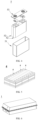
- FIG. 3 shows a secondary battery 5 of a prismatic structure as an example.
- the outer package may include a housing 51 and a cover plate 53, where the housing 51 may include a bottom plate and a side plate connected to the bottom plate, and the bottom plate and the side plate enclose an accommodation cavity.
- the housing 51 has an opening communicating to the accommodation cavity, and the cover plate 53 can cover the opening to close the accommodation cavity.
- the positive electrode plate, the negative electrode plate and the separator can form an electrode assembly 52 through a winding process or a lamination process.
- the electrode assembly 52 is packaged in the accommodation cavity.
- the electrolyte solution is infiltrated in the electrode assembly 52.
- the number of electrode assemblies 52 contained in the secondary battery 5 may be one or more, and a person skilled in the art can select according to specific actual needs.
- the secondary battery may be assembled into a battery module.
- the battery module may include one or more secondary batteries, and the specific number of secondary batteries in a battery module may be selected by a person skilled in the art depending on practical applications and capacity of the battery module.
- FIG. 5 shows a battery module 4 as an example.
- a plurality of secondary batteries 5 may be arranged in sequence along the length direction of the battery module 4. Of course, they may also be arranged in any other manner. Further, the plurality of secondary batteries 5 may be fixed by fasteners.
- the battery module 4 may further include a shell that provides an accommodation space.
- the plurality of secondary batteries 5 are accommodated in the accommodation space.
- the battery module may be assembled to form a battery pack.
- the battery pack may include one or more battery modules, and the specific number of battery modules in a battery pack may be selected by a person skilled in the art depending on practical applications and capacity of the battery pack.
- FIG. 6 and FIG. 7 show a battery pack 1 as an example.
- the battery pack 1 may include a battery box and a plurality of battery modules 4 disposed in the battery box.
- the battery box includes an upper box 2 and a lower box 3, and the upper box 2 can cover the lower box 3 and form a closed space for accommodating the battery modules 4.
- the plurality of battery modules 4 may be arranged in the battery box in any manner.
- this application further provides an electrical device, which includes at least one of the secondary battery, battery module or battery pack provided in this application.
- the secondary battery, battery module or battery pack may be used as a power source for the electrical device, and may also be used as an energy storage unit for the electrical device.
- the electrical device may include a mobile device (such as a mobile phone, a laptop, etc.), an electric vehicle (such as a pure electric vehicle, a hybrid electric vehicle, a plug-in hybrid electric vehicle, an electric bicycle, an electric scooter, an electric golf cart, an electric truck, etc.), an electric train, a ship and a satellite, an energy storage system, etc., but is not limited to these.
- a secondary battery, a battery module or a battery pack can be selected according to the use requirements thereof.
- FIG. 8 is an electrical device as an example.
- the electrical device is a pure electric vehicle, a hybrid electric vehicle, or a plug-in hybrid electric vehicle, etc.
- a battery pack or a battery module may be used.
- the SEM image is shown in FIG. 1 .
- the SEM image is shown in FIG. 2 .
- the first lithium-nickel transition metal oxide particles and the second lithium-nickel transition metal oxide particles sequentially prepared were mixed at a mass ratio of 2:8 to prepare the positive active material.
- the positive active material, polyvinylidene difluoride and conductive carbon black were mixed at a mass ratio of 90:5:5, then added with N-methyl-pyrrolidone (NMP), and stirred at 1000 r/min for 1 h until the mixture was uniformly mixed to obtain a positive electrode slurry.
- NMP N-methyl-pyrrolidone
- the positive electrode slurry was uniformly coated on one side surface of an aluminum foil current collector with a thickness of 13 microns, and after the coating was completed, dried in a drying oven at 100 °C, cold pressed, and slitted to obtain the positive electrode plate.
- a mixed solution of ethylene carbonate (EC) and diethyl carbonate (DEC) was mixed at a volume ratio of 1:2 to obtain a mixed solvent. Then sufficiently dried lithium hexafluorophosphate was dissolved in the mixed solvent in a glove box in an argon-containing atmosphere, and uniformly mixed to obtain an electrolyte solution. The concentration of the lithium salt in the electrolyte solution was 1 mol/L.
- the negative active materials graphite, sodium carboxymethyl cellulose, styrene-butadiene rubber, and acetylene black were mixed in a mass ratio of 96:1:1:2, added with deionized water, and uniformly stirred in a stirrer, and then the slurry was coated on both side surfaces of a copper foil with a thickness of 8 microns, dried in an oven at 100 °C, cold pressed, and slitted to obtain the negative electrode plate.
- the positive electrode plate, the separator, and the negative electrode plate were stacked in sequence to ensure that the positive and negative electrode plates cannot contact each other, and then they were wound into a bare cell through a winding needle, loaded into a prismatic aluminum housing, injected with an electrolyte solution, and subjected to the steps of standing, forming, capacity, etc. to prepare the battery cell.
- the first lithium-nickel transition metal oxide particles and the second lithium-nickel transition metal oxide particles prepared were mixed at a mass ratio of 3:7 to prepare the positive active material.
- the preparation procedure of the secondary battery was the same as that of Embodiment 1, and the positive active material of Embodiment 2 was used as the positive active material.
- the first lithium-nickel transition metal oxide particles and the second lithium-nickel transition metal oxide particles prepared were mixed at a mass ratio of 6:4 to prepare the positive active material.
- the first lithium-nickel transition metal oxide particles obtained above and aluminum oxide were mixed in a mixer at a molar ratio of 1:0.005, and then sintered at 400 °C in an oxygen-containing atmosphere to obtain a first lithium-nickel transition metal oxide having an Al 2 O 3 island-shaped cladding layer with a thickness of 2 nm on its surface. See Table 1 for specific powder parameters.
- the first lithium-nickel transition metal oxide particles and the second lithium-nickel transition metal oxide particles prepared were mixed at a mass ratio of 6:4 to prepare the positive active material.
- the first lithium-nickel transition metal oxide particles obtained above and boric acid were mixed in a mixer at a molar ratio of 1:0.01, and then sintered at 400 °C in an oxygen-containing atmosphere to obtain a first lithium-nickel transition metal oxide having a B 2 O 3 layered cladding layer with a thickness of 5 nm on its surface. See Table 1 for specific powder parameters.
- the first lithium-nickel transition metal oxide particles and the second lithium-nickel transition metal oxide particles prepared were mixed at a mass ratio of 6:4 to prepare the positive active material.
- the first lithium-nickel transition metal oxide particles obtained above, boric acid and aluminum oxide were mixed in a mixer at a molar ratio of 1:0.02:0.005, and then sintered at 400 °C in an oxygen-containing atmosphere to obtain a first lithium-nickel transition metal oxide having a cladding layer with a thickness of 20 nm on its surface, with an Al 2 O 3 island-shaped cladding layer inside and a B 2 O 3 island-shaped cladding layer outside. See Table 1 for specific powder parameters.
- the first lithium-nickel transition metal oxide particles and the second lithium-nickel transition metal oxide particles prepared were mixed at a mass ratio of 6:4 to prepare the positive active material.
- the second lithium-nickel transition metal oxide particles obtained above and aluminum oxide were mixed in a mixer at a molar ratio of 1:0.005, and then sintered at 400 °C in an oxygen-containing atmosphere to obtain a second lithium-nickel transition metal oxide having an Al 2 O 3 island-shaped cladding layer with a thickness of 2 nm on its surface. See Table 1 for specific powder parameters.
- the first lithium-nickel transition metal oxide particles and the second lithium-nickel transition metal oxide particles prepared were mixed at a mass ratio of 6:4 to prepare the positive active material.
- the second lithium-nickel transition metal oxide particles obtained above and boric acid were mixed in a mixer at a molar ratio of 1:0.01, and then sintered at 400 °C in an oxygen-containing atmosphere to obtain a second lithium-nickel transition metal oxide having a B 2 O 3 layered cladding layer with a thickness of 5 nm on its surface. See Table 1 for specific powder parameters.
- the first lithium-nickel transition metal oxide particles and the second lithium-nickel transition metal oxide particles prepared were mixed at a mass ratio of 6:4 to prepare the positive active material.
- the second lithium-nickel transition metal oxide particles obtained above, boric acid and aluminum oxide were mixed in a mixer at a molar ratio of 1:0.02:0.005, and then sintered at 400 °C in an oxygen-containing atmosphere to obtain a second lithium-nickel transition metal oxide having a cladding layer with a thickness of 20 nm on its surface, with an Al 2 O 3 island-shaped cladding layer inside and a B 2 O 3 island-shaped cladding layer outside. See Table 1 for specific powder parameters.
- the first lithium-nickel transition metal oxide particles and the second lithium-nickel transition metal oxide particles prepared were mixed at a mass ratio of 6:4 to prepare the positive active material.
- the first lithium-nickel transition metal oxide particles and the second lithium-nickel transition metal oxide particles prepared were mixed at a mass ratio of 1:9 to prepare the positive active material.
- the first lithium-nickel transition metal oxide particles and the second lithium-nickel transition metal oxide particles prepared were mixed at a mass ratio of 9:1 to prepare the positive active material.
- the first lithium-nickel transition metal oxide particles and the second lithium-nickel transition metal oxide particles prepared were mixed at a mass ratio of 5:5 to prepare the positive active material.
- the first lithium-nickel transition metal oxide particles prepared in Embodiment 12 and the second lithium-nickel transition metal oxide particles prepared in Embodiment 12 were mixed at a mass ratio of 0.5:9.5 to prepare the positive active material.
- the first lithium-nickel transition metal oxide particles prepared in Embodiment 12 and the second lithium-nickel transition metal oxide particles prepared in Embodiment 12 were mixed at a mass ratio of 9.5:0.5 to prepare the positive active material.
- the first lithium-nickel transition metal oxide particles and the second lithium-nickel transition metal oxide particles prepared were mixed at a mass ratio of 5:5 to prepare the positive active material.
- the first lithium-nickel transition metal oxide particles and the second lithium-nickel transition metal oxide particles prepared were mixed at a mass ratio of 5:5 to prepare the positive active material.
- the first lithium-nickel transition metal oxide particles and the second lithium-nickel transition metal oxide particles prepared were mixed at a mass ratio of 5:5 to prepare the positive active material.
- the first lithium-nickel transition metal oxide particles and the second lithium-nickel transition metal oxide particles prepared were mixed at a mass ratio of 5:5 to prepare the positive active material.
- the first lithium-nickel transition metal oxide particles and the second lithium-nickel transition metal oxide particles prepared were mixed at a mass ratio of 6:4 to prepare the positive active material.
- the first lithium-nickel transition metal oxide particles and the second lithium-nickel transition metal oxide particles prepared were mixed at a mass ratio of 5:5 to prepare the positive active material.
- the first lithium-nickel transition metal oxide particles and the second lithium-nickel transition metal oxide particles prepared were mixed at a mass ratio of 4:6 to prepare the positive active material.
- the first lithium-nickel transition metal oxide particles and the second lithium-nickel transition metal oxide particles prepared were mixed at a mass ratio of 3:7 to prepare the positive active material.
- the first lithium-nickel transition metal oxide particles and the second lithium-nickel transition metal oxide particles prepared were mixed at a mass ratio of 5:5 to prepare the positive active material.
- the first lithium-nickel transition metal oxide particles and the second lithium-nickel transition metal oxide particles prepared were mixed at a mass ratio of 5:5 to prepare the positive active material.
- the first lithium-nickel transition metal oxide particles and the second lithium-nickel transition metal oxide particles prepared were mixed at a mass ratio of 7:3 to prepare the positive active material.
- the first lithium-nickel transition metal oxide particles and the second lithium-nickel transition metal oxide particles prepared were mixed at a mass ratio of 7:3 to prepare the positive active material.
- the first lithium-nickel transition metal oxide particles and the second lithium-nickel transition metal oxide particles prepared were mixed at a mass ratio of 7:3 to prepare the positive active material.
- the first lithium-nickel transition metal oxide particles and the second lithium-nickel transition metal oxide particles prepared were mixed at a mass ratio of 7:3 to prepare the positive active material.
- the first lithium-nickel transition metal oxide particles and the second lithium-nickel transition metal oxide particles prepared were mixed at a mass ratio of 7:3 to prepare the positive active material.
- the first lithium-nickel transition metal oxide particles and the second lithium-nickel transition metal oxide particles prepared were mixed at a mass ratio of 7:3 to prepare the positive active material.
- the first lithium-nickel transition metal oxide particles and the second lithium-nickel transition metal oxide particles prepared were mixed at a mass ratio of 7:3 to prepare the positive active material.
- the first lithium-nickel transition metal oxide particles and the second lithium-nickel transition metal oxide particles prepared were mixed at a mass ratio of 7:3 to prepare the positive active material.
- the first lithium-nickel transition metal oxide particles and the second lithium-nickel transition metal oxide particles prepared were mixed at a mass ratio of 7:3 to prepare the positive active material.
- the first lithium-nickel transition metal oxide particles and the second lithium-nickel transition metal oxide particles prepared were mixed at a mass ratio of 7:3 to prepare the positive active material.
- the first lithium-nickel transition metal oxide particles and the second lithium-nickel transition metal oxide particles prepared were mixed at a mass ratio of 7:3 to prepare the positive active material.
- the first lithium-nickel transition metal oxide particles and the second lithium-nickel transition metal oxide particles prepared were mixed at a mass ratio of 7:3 to prepare the positive active material.
- Tests of particle diameter size types Dv10, Dv50 and Dv90.
- Equipment model Malvern 2000 (MasterSizer 2000) laser particle size analyzer, reference standard process: GB/T19077-2016/ISO 13320:2009, detailed test process: an appropriate amount of the sample to be tested (the sample concentration was guaranteed to have a 8% to 12% shading degree) was taken, added with 20 mL anhydrous ethanol, and subjected to ultrasonic treatment for 5 min (53 KHz/120 W) to ensure the complete dispersion of the sample, and then the sample was measured according to the GB/T19077-2016/ISO 13320:2009 standard. In order to avoid the aggregation in the drying process affecting the particle size test, the washed and wet sample was taken for the dispersion test.
- the first lithium-nickel transition metal oxide and the second lithium-nickel transition metal oxide were tested respectively by the above process to obtain the respective volume particle diameter distribution curves; and the positive film layer of the positive electrode plate was scraped and tested by the above process, and the volume particle diameter distribution curve obtained was a bimodal curve.
- the bimodal curve was fitted by peak separation using origin to obtain a small particle fitted peak pattern and a large particle fitted peak pattern.
- the small particle fitted peak pattern basically coincided with the volume particle diameter distribution curve of the first lithium-nickel transition metal oxide
- the large particle fitted peak pattern basically coincided with the volume particle diameter distribution curve of the second lithium-nickel transition metal oxide, indicating that the result of peak separation fitting was reliable.
- D V 10, D V 50 and D V 90 recorded in or used in Table 1 were obtained from the volume particle diameter distribution curves of the first lithium-nickel transition metal oxide and the second lithium-nickel transition metal oxide.
- the particle strength was characterized by a dynamic ultra-micro hardness tester.
- the particle strength of the material was tested with a 50 micron probe under pressure of 0 mN to 20 mN, and the force value and pressure when the material was broken were recorded.
- the first lithium-nickel transition metal oxide powder was tested by an electron microscope. The number of particles per square micron was recorded in ten different regions at 30,000 magnification, and the average value of the ten regions was taken as the number of monocrystallines per square micron.
- the number of the second lithium-nickel transition metal oxide was tested by an electron microscope. The number of particles per square micron was recorded in ten different regions at 30,000 magnification, and the average value of the ten regions was taken as the number of primary particles per square micron.
- the material was analyzed by TEM.
- the thickness of the cladding layer of the material was measured at ten points, and the average value was taken.
- the positive electrode slurry was coated on both side surfaces of a 13 ⁇ m aluminum foil with a coating thickness of 110 ⁇ m on one side, data on the compaction density and elongation rate were collected by a cold press after drying, and the compaction density corresponding to the elongation rate of 0.8% was used as a test value of the compaction density of the electrode plate of the positive active material.
- Elongation rate (length of the electrode plate after cold pressing - length of the electrode plate before cold pressing) / length of the electrode plate before cold pressing ⁇ 100%
- Gram capacity refers to a ratio of the capacitance that can be released by the active material inside the battery to the mass of the active material.
- a cycle refers to charging and discharging once with a constant current and then a constant voltage at a rate of 1 C.
- the first cycle is denoted as C0
- the nth cycle is Cn
- the capacity retention rate of each cycle is Cn/C0.
- the lithium-ion battery was first charged to 4.3 V with a constant current of 1/3 C, then charged at a constant voltage with a current of 0.025 C, and charged to 4.3 V.
- the volume of the lithium-ion battery was measured as V0 by placing the lithium-ion battery into deionized water using a drainage method, and then stored at a condition of 70 °C.
- the battery cell volume change was obtained every six days, and the nth time was Vn.
- Volume expansion rate (%) of the lithium-ion battery after storage at 70 °C (Vn - V0) / V0 ⁇ 100%.
- the battery cell was charged to 4.3 V at a constant current of 1 C, then charged at a constant voltage with a current of 0.05 C, charged to 4.3 V, then discharged to 2.8 V at a constant current of 1 C, and discharged at a constant voltage with a current of 0.05 C.
- the measured capacity was recorded as C0.
- the battery cell is charged to 4.3 V at 1 C current, and charged at a constant voltage with a current of 0.05 C.
- the fully charged battery cell was stored in a constant temperature furnace at 60 °C.
- the battery cell was taken out every 30 days, and at 25 °C, discharged to 2.8 V at a constant current of 1 C, and then discharged at a constant voltage of 0.05 C.
- the measured capacity was Cn.
- Capacity retention rate Cn / C0.
- the second step was repeated to obtain a variation diagram of a battery capacity retention rate over time.
- the lithium-ion battery was charged to a voltage of 4.3 V at a constant current of 1 C, then charged at a 4.3 V constant voltage with a current of 0.05 C, and subsequently discharged at a constant current of 1 C until the final voltage was 2.8 V and the capacity was C1.
- the above steps were sequentially repeated, and the nth measured capacity was Cn.
- Capacity retention rate (%) (the nth discharge capacity / the first cycle discharge capacity) ⁇ 100%. The cycle was continued until the capacity retention rate of the battery cell decayed to 80%.
- Table 2 Compaction density (g/cm 3 ) Gram Capacity (mAh/g) Capacity retention rate after 50 cycles Capacity retention rate after 100 cycles Storage gas production at 70°C for 40 days (mL/Ah) Storage performance (capacity retention rate at 60 °C for 50 days) Number of cycles at 25 °C to a capacity retention rate of 80% Embodiment 1 3.50 185 97.0% 96.5% 7.00 97.0% 2500 Embodiment 2 3.51 210 96.2% 96.0% 9.00 97.3% 2600 Embodiment 3 3.60 215 95.7% 95.5% 11.20 97.1% 2550 Embodiment 4 3.60 208 97.1% 96.8% 8.60 97.7% 2700 Embodiment 5 3.60 215 96.0% 95.8% 9.60 96.9% 2400 Embodiment 6 3.60 214 97.2% 96.6% 8.20 97.8% 2590 Embodiment 7 3.60 209 97
- Embodiments 12 and 15 to 17 From the comparison of Embodiments 12 and 15 to 17, it can be seen that when the Zr content in the first lithium-nickel transition metal oxide and the second lithium-nickel transition metal oxide was increased, it was conducive to increasing the particle strength and thus improving the cycle performance, but the specific capacity of the battery was reduced. From the comparison of Embodiments 23 and 24, it can be seen that on the basis of no obvious increase in the Zr content, reducing the ratio d of the Zr content in the two materials limited the exertion of material capacity and cycle performance, and it was difficult to achieve the optimal solution for mixed system capacity and cycle.
- Embodiments 12 and 19 to 21 From the comparison of Embodiments 12 and 19 to 21, it can be seen that the number of monocrystalline and polycrystalline particles per unit area was large, and the material capacity was improved, but the material cycle performance deteriorated significantly. From the comparison of Embodiments 25 to 33, it can be seen that the particle diameter distribution concentration degree S value mainly affected the compaction density of the material, and the larger the S value in a certain range, the higher the compaction density, but an excessively large value would affect and deteriorate the material cycle performance and compaction density. The capacity and cycle of the material were decreased as D v 50 was increased, but for storage performance, D v 50 being higher would have an improvement effect.
Landscapes
- Chemical & Material Sciences (AREA)
- Chemical Kinetics & Catalysis (AREA)
- Electrochemistry (AREA)
- General Chemical & Material Sciences (AREA)
- Engineering & Computer Science (AREA)
- Composite Materials (AREA)
- Inorganic Chemistry (AREA)
- Materials Engineering (AREA)
- Manufacturing & Machinery (AREA)
- Battery Electrode And Active Subsutance (AREA)
Applications Claiming Priority (1)
| Application Number | Priority Date | Filing Date | Title |
|---|---|---|---|
| PCT/CN2023/072837 WO2024152233A1 (zh) | 2023-01-18 | 2023-01-18 | 正极活性材料、正极极片、二次电池和用电装置 |
Publications (2)
| Publication Number | Publication Date |
|---|---|
| EP4567923A1 true EP4567923A1 (de) | 2025-06-11 |
| EP4567923A4 EP4567923A4 (de) | 2026-03-11 |
Family
ID=88564007
Family Applications (1)
| Application Number | Title | Priority Date | Filing Date |
|---|---|---|---|
| EP23916720.8A Pending EP4567923A4 (de) | 2023-01-18 | 2023-01-18 | Positivelektrodenaktivmaterial, positivelektrodenfolie, sekundärbatterie und elektrische vorrichtung |
Country Status (4)
| Country | Link |
|---|---|
| US (1) | US20250140849A1 (de) |
| EP (1) | EP4567923A4 (de) |
| CN (1) | CN117015872B (de) |
| WO (1) | WO2024152233A1 (de) |
Families Citing this family (7)
| Publication number | Priority date | Publication date | Assignee | Title |
|---|---|---|---|---|
| CN117894974A (zh) * | 2023-12-06 | 2024-04-16 | 蔚来电池科技(安徽)有限公司 | 正极活性材料及其制备方法、二次电池和装置 |
| CN120261571A (zh) * | 2024-01-02 | 2025-07-04 | 宁德时代新能源科技股份有限公司 | 正极材料及其制备方法、正极极片、电池和用电装置 |
| CN119833566A (zh) * | 2024-03-14 | 2025-04-15 | 宁德时代新能源科技股份有限公司 | 正极极片、制备方法、电池及用电设备 |
| CN120581726A (zh) * | 2024-08-05 | 2025-09-02 | 宁德时代新能源科技股份有限公司 | 电池单体、二次电池及用电装置 |
| CN118970209A (zh) * | 2024-08-05 | 2024-11-15 | 宁德时代新能源科技股份有限公司 | 电池单体、二次电池及用电装置 |
| CN118658962B (zh) * | 2024-08-15 | 2025-01-24 | 宁波容百新能源科技股份有限公司 | 一种正极极片及其制备方法和应用 |
| CN119852314B (zh) * | 2024-12-31 | 2026-01-09 | 江苏时代新能源科技有限公司 | 锂离子二次电池、用电装置 |
Family Cites Families (8)
| Publication number | Priority date | Publication date | Assignee | Title |
|---|---|---|---|---|
| WO2015045340A1 (ja) * | 2013-09-30 | 2015-04-02 | 三洋電機株式会社 | 非水電解質二次電池用正極活物質及びそれを用いた非水電解質二次電池 |
| KR102012427B1 (ko) * | 2015-11-30 | 2019-08-21 | 주식회사 엘지화학 | 이차전지용 양극활물질, 이를 포함하는 이차전지용 양극 및 이차전지 |
| KR102420737B1 (ko) * | 2017-08-29 | 2022-07-14 | 스미토모 긴조쿠 고잔 가부시키가이샤 | 비수계 전해질 이차 전지용 정극 활물질과 그의 제조 방법, 및 이 정극 활물질을 이용한 비수계 전해질 이차 전지 |
| JP7052806B2 (ja) * | 2017-10-31 | 2022-04-12 | 住友金属鉱山株式会社 | 非水系電解質二次電池用正極活物質、非水系電解質二次電池及び非水系電解質二次電池用正極活物質の製造方法 |
| EP3613706A3 (de) * | 2018-08-22 | 2020-03-04 | Ecopro Bm Co., Ltd. | Positivelektrodenaktivmaterial und lithiumsekundärbatterie damit |
| KR102754047B1 (ko) * | 2018-10-25 | 2025-01-15 | 삼성에스디아이 주식회사 | 복합양극활물질, 이를 포함한 양극, 리튬전지 및 그 제조 방법 |
| CN111384371B (zh) * | 2018-12-29 | 2021-05-07 | 宁德时代新能源科技股份有限公司 | 一种抗压的正极活性材料及电化学储能装置 |
| CN111384372B (zh) * | 2018-12-29 | 2021-03-23 | 宁德时代新能源科技股份有限公司 | 一种高压实密度正极材料及电化学储能装置 |
-
2023
- 2023-01-18 EP EP23916720.8A patent/EP4567923A4/de active Pending
- 2023-01-18 WO PCT/CN2023/072837 patent/WO2024152233A1/zh not_active Ceased
- 2023-01-18 CN CN202380010253.4A patent/CN117015872B/zh active Active
-
2024
- 2024-12-30 US US19/005,885 patent/US20250140849A1/en active Pending
Also Published As
| Publication number | Publication date |
|---|---|
| US20250140849A1 (en) | 2025-05-01 |
| EP4567923A4 (de) | 2026-03-11 |
| CN117015872B (zh) | 2025-09-26 |
| WO2024152233A1 (zh) | 2024-07-25 |
| CN117015872A (zh) | 2023-11-07 |
Similar Documents
| Publication | Publication Date | Title |
|---|---|---|
| EP4567923A1 (de) | Positivelektrodenaktivmaterial, positivelektrodenfolie, sekundärbatterie und elektrische vorrichtung | |
| KR102622786B1 (ko) | 2차 전지, 그의 제조방법 및 그와 관련된 배터리 모듈, 배터리 팩 및 디바이스 | |
| US20240097124A1 (en) | Positive active material, positive electrode plate and lithium-ion secondary battery | |
| EP4075547A1 (de) | Positivelektrodenaktivmaterial und verfahren zu seiner herstellung, sekundärbatterie, batteriemodul, batteriepack und vorrichtung | |
| KR102599823B1 (ko) | 이차 전지, 그 제조 방법 및 이차 전지를 포함하는 장치 | |
| US20230231134A1 (en) | Secondary battery and electric apparatus | |
| KR20230042208A (ko) | 고-니켈 양극 활물질, 이의 제조 방법, 이를 포함하는 리튬 이온 전지, 전지 모듈, 전지 팩 및 전기 장치 | |
| EP4224579A1 (de) | Positivelektrodenaktivmaterial und zugehörige elektrodenfolie, sekundärbatterie, batteriemodul, batteriepack und vorrichtung | |
| EP4220767B1 (de) | Modifiziertes ternäres positivelektrodenmaterial mit hohem nickelgehalt und herstellungsverfahren dafür sowie stromverbrauchende vorrichtung | |
| KR102847477B1 (ko) | 이차 전지 및 이를 포함하는 전기 장치 | |
| EP4672355A1 (de) | Batteriezelle, batterie und elektrische vorrichtung | |
| EP4358182A1 (de) | Modifiziertes lithiumreiches manganbasiertes material, modifikationsverfahren für lithiumreiches manganbasiertes material, sekundärbatterie und elektrische vorrichtung | |
| EP4322259A1 (de) | Positivelektrodenmaterial, herstellungsverfahren dafür und sekundärbatterie damit | |
| EP4510230A1 (de) | Positivelektrodenaktivmaterial, herstellungsverfahren dafür, sekundärbatterie und elektrische vorrichtung | |
| EP4611068A1 (de) | Batterie und elektrische vorrichtung | |
| EP4481852A1 (de) | Positivelektrodenaktivmaterial, positivelektrodenfolie, elektrochemische energiespeichervorrichtung, sekundärbatterie, elektrische vorrichtung und herstellungsverfahren | |
| CN118693274A (zh) | 正极活性材料、正极极片、电池及用电装置 | |
| EP4593113A1 (de) | Positivelektrodenmaterial und herstellungsverfahren dafür sowie sekundärbatterie und elektrische vorrichtung damit | |
| EP4560731A1 (de) | Positivelektrodenaktivmaterial und herstellungsverfahren dafür, positivelektrodenplatte, sekundärbatterie, batteriemodul, batteriepack und elektrische vorrichtung | |
| CN118696435B (zh) | 正极活性材料及其制备方法、正极极片、二次电池和用电装置 | |
| EP4601040A1 (de) | Positivelektrodenaktivmaterial, positivelektrodenfolie, sekundärbatterie, elektrische vorrichtung und herstellungsverfahren | |
| KR20260021754A (ko) | 음극 시트, 이차 전지 및 전기 장치 | |
| JP2024527841A (ja) | 正極活物質及びその製造方法、極板、二次電池及び電力消費装置 | |
| EP4607609A1 (de) | Positivelektrodenaktivmaterial, positivpolteil, sekundärbatterie und elektrische vorrichtung | |
| EP4664561A1 (de) | Sekundärbatterie und elektrische vorrichtung |
Legal Events
| Date | Code | Title | Description |
|---|---|---|---|
| STAA | Information on the status of an ep patent application or granted ep patent |
Free format text: STATUS: THE INTERNATIONAL PUBLICATION HAS BEEN MADE |
|
| PUAI | Public reference made under article 153(3) epc to a published international application that has entered the european phase |
Free format text: ORIGINAL CODE: 0009012 |
|
| STAA | Information on the status of an ep patent application or granted ep patent |
Free format text: STATUS: REQUEST FOR EXAMINATION WAS MADE |
|
| 17P | Request for examination filed |
Effective date: 20250306 |
|
| AK | Designated contracting states |
Kind code of ref document: A1 Designated state(s): AL AT BE BG CH CY CZ DE DK EE ES FI FR GB GR HR HU IE IS IT LI LT LU LV MC ME MK MT NL NO PL PT RO RS SE SI SK SM TR |
|
| A4 | Supplementary search report drawn up and despatched |
Effective date: 20260210 |
|
| RIC1 | Information provided on ipc code assigned before grant |
Ipc: H01M 4/36 20060101AFI20260204BHEP Ipc: H01M 4/525 20100101ALI20260204BHEP Ipc: H01M 4/505 20100101ALI20260204BHEP Ipc: H01M 4/485 20100101ALI20260204BHEP Ipc: H01M 10/0525 20100101ALI20260204BHEP |