EP4567914A1 - Drying device for manufacturing electrode - Google Patents
Drying device for manufacturing electrode Download PDFInfo
- Publication number
- EP4567914A1 EP4567914A1 EP24767324.7A EP24767324A EP4567914A1 EP 4567914 A1 EP4567914 A1 EP 4567914A1 EP 24767324 A EP24767324 A EP 24767324A EP 4567914 A1 EP4567914 A1 EP 4567914A1
- Authority
- EP
- European Patent Office
- Prior art keywords
- base material
- electrode base
- electrode
- drying device
- heating
- Prior art date
- Legal status (The legal status is an assumption and is not a legal conclusion. Google has not performed a legal analysis and makes no representation as to the accuracy of the status listed.)
- Pending
Links
Images


Classifications
-
- F—MECHANICAL ENGINEERING; LIGHTING; HEATING; WEAPONS; BLASTING
- F26—DRYING
- F26B—DRYING SOLID MATERIALS OR OBJECTS BY REMOVING LIQUID THEREFROM
- F26B3/00—Drying solid materials or objects by processes involving the application of heat
- F26B3/28—Drying solid materials or objects by processes involving the application of heat by radiation, e.g. from the sun
- F26B3/30—Drying solid materials or objects by processes involving the application of heat by radiation, e.g. from the sun from infrared-emitting elements
-
- F—MECHANICAL ENGINEERING; LIGHTING; HEATING; WEAPONS; BLASTING
- F26—DRYING
- F26B—DRYING SOLID MATERIALS OR OBJECTS BY REMOVING LIQUID THEREFROM
- F26B13/00—Machines and apparatus for drying fabrics, fibres, yarns, or other materials in long lengths, with progressive movement
- F26B13/06—Machines and apparatus for drying fabrics, fibres, yarns, or other materials in long lengths, with progressive movement with movement in a sinuous or zig-zag path
- F26B13/08—Machines and apparatus for drying fabrics, fibres, yarns, or other materials in long lengths, with progressive movement with movement in a sinuous or zig-zag path using rollers
-
- F—MECHANICAL ENGINEERING; LIGHTING; HEATING; WEAPONS; BLASTING
- F26—DRYING
- F26B—DRYING SOLID MATERIALS OR OBJECTS BY REMOVING LIQUID THEREFROM
- F26B13/00—Machines and apparatus for drying fabrics, fibres, yarns, or other materials in long lengths, with progressive movement
- F26B13/10—Arrangements for feeding, heating or supporting materials; Controlling movement, tension or position of materials
-
- F—MECHANICAL ENGINEERING; LIGHTING; HEATING; WEAPONS; BLASTING
- F26—DRYING
- F26B—DRYING SOLID MATERIALS OR OBJECTS BY REMOVING LIQUID THEREFROM
- F26B21/00—Arrangements for supplying or controlling air or other gases for drying solid materials or objects
- F26B21/30—Controlling, e.g. regulating, parameters of gas supply
-
- F—MECHANICAL ENGINEERING; LIGHTING; HEATING; WEAPONS; BLASTING
- F26—DRYING
- F26B—DRYING SOLID MATERIALS OR OBJECTS BY REMOVING LIQUID THEREFROM
- F26B21/00—Arrangements for supplying or controlling air or other gases for drying solid materials or objects
- F26B21/50—Ducting arrangements from the source of air or other gases to the materials or objects being dried
-
- F—MECHANICAL ENGINEERING; LIGHTING; HEATING; WEAPONS; BLASTING
- F26—DRYING
- F26B—DRYING SOLID MATERIALS OR OBJECTS BY REMOVING LIQUID THEREFROM
- F26B25/00—Details of general application not covered by group F26B21/00 or F26B23/00
- F26B25/009—Alarm systems; Safety systems, e.g. preventing fire and explosions
-
- H—ELECTRICITY
- H01—ELECTRIC ELEMENTS
- H01M—PROCESSES OR MEANS, e.g. BATTERIES, FOR THE DIRECT CONVERSION OF CHEMICAL ENERGY INTO ELECTRICAL ENERGY
- H01M4/00—Electrodes
- H01M4/02—Electrodes composed of, or comprising, active material
- H01M4/04—Processes of manufacture in general
-
- H—ELECTRICITY
- H01—ELECTRIC ELEMENTS
- H01M—PROCESSES OR MEANS, e.g. BATTERIES, FOR THE DIRECT CONVERSION OF CHEMICAL ENERGY INTO ELECTRICAL ENERGY
- H01M4/00—Electrodes
- H01M4/02—Electrodes composed of, or comprising, active material
- H01M4/04—Processes of manufacture in general
- H01M4/0471—Processes of manufacture in general involving thermal treatment, e.g. firing, sintering, backing particulate active material, thermal decomposition, pyrolysis
-
- H—ELECTRICITY
- H05—ELECTRIC TECHNIQUES NOT OTHERWISE PROVIDED FOR
- H05B—ELECTRIC HEATING; ELECTRIC LIGHT SOURCES NOT OTHERWISE PROVIDED FOR; CIRCUIT ARRANGEMENTS FOR ELECTRIC LIGHT SOURCES, IN GENERAL
- H05B1/00—Details of electric heating devices
- H05B1/02—Automatic switching arrangements specially adapted to apparatus ; Control of heating devices
- H05B1/0227—Applications
- H05B1/023—Industrial applications
-
- H—ELECTRICITY
- H05—ELECTRIC TECHNIQUES NOT OTHERWISE PROVIDED FOR
- H05B—ELECTRIC HEATING; ELECTRIC LIGHT SOURCES NOT OTHERWISE PROVIDED FOR; CIRCUIT ARRANGEMENTS FOR ELECTRIC LIGHT SOURCES, IN GENERAL
- H05B3/00—Ohmic-resistance heating
- H05B3/0033—Heating devices using lamps
- H05B3/0038—Heating devices using lamps for industrial applications
-
- H—ELECTRICITY
- H05—ELECTRIC TECHNIQUES NOT OTHERWISE PROVIDED FOR
- H05B—ELECTRIC HEATING; ELECTRIC LIGHT SOURCES NOT OTHERWISE PROVIDED FOR; CIRCUIT ARRANGEMENTS FOR ELECTRIC LIGHT SOURCES, IN GENERAL
- H05B2203/00—Aspects relating to Ohmic resistive heating covered by group H05B3/00
- H05B2203/032—Heaters specially adapted for heating by radiation heating
-
- Y—GENERAL TAGGING OF NEW TECHNOLOGICAL DEVELOPMENTS; GENERAL TAGGING OF CROSS-SECTIONAL TECHNOLOGIES SPANNING OVER SEVERAL SECTIONS OF THE IPC; TECHNICAL SUBJECTS COVERED BY FORMER USPC CROSS-REFERENCE ART COLLECTIONS [XRACs] AND DIGESTS
- Y02—TECHNOLOGIES OR APPLICATIONS FOR MITIGATION OR ADAPTATION AGAINST CLIMATE CHANGE
- Y02E—REDUCTION OF GREENHOUSE GAS [GHG] EMISSIONS, RELATED TO ENERGY GENERATION, TRANSMISSION OR DISTRIBUTION
- Y02E60/00—Enabling technologies; Technologies with a potential or indirect contribution to GHG emissions mitigation
- Y02E60/10—Energy storage using batteries
Definitions
- the present invention relates to a drying device for electrode manufacturing, and relates to a drying device for electrode manufacturing capable of preventing overheating of an electrode base material due to residual heat of a heating part when running of the electrode base material is stopped.
- lithium secondary batteries charge and discharge are formed during a process that lithium ions moving from a positive electrode are reversibly inserted and detached to a negative electrode, and the positive electrode and the negative electrode are laminated so that a separator is interposed therebetween, thereby forming an electrode base material assembly.
- the secondary batteries are classified into cylindrical batteries and rectangular batteries in which the electrode base material assembly is embedded in a cylindrical or rectangular metal can, and pouch-type batteries in which the electrode base material assembly is embedded in a pouch-type case of an aluminum laminate sheet.
- the secondary battery can be formed by inserting an electrode base material assembly consisting of a positive electrode, a negative electrode, and a separator into a case and then sealing it.
- the electrode base material assembly can be formed by winding the positive electrode and the negative electrode in which the separator is interposed therebetween multiple times in the form of a jelly roll, or laminating them in multiple layers.
- an electrode base material such as the positive electrode or the negative electrode in the secondary battery
- a process of drying the electrode base material is performed.
- the electrode base material is dried while passing through a drying part in a roll-to-roll manner.
- the drying part dries the electrode base material using a heating lamp.
- the present invention is intended to provide a drying device for electrode manufacturing capable of preventing an electrode base material from overheating due to residual heat of a heating part when running of the electrode base material is stopped.
- the present invention is intended to provide a drying device for electrode manufacturing capable of blocking residual heat of a heating part from being transferred to an electrode base material, and cooling the surface of the electrode base material, when running of the electrode base material is stopped.
- a drying device for electrode manufacturing comprises a transfer part for transferring an electrode base material, a heating part for applying heat to the electrode base material under transfer, a position adjustment part for adjusting a position of the heating part, a first cooling part for spraying air toward the electrode base material located on the transfer part, and a control part for operating the first cooling part when the transfer of the electrode base material is stopped.
- the first cooling part may be provided to spray air toward a surface of the electrode base material located on the transfer part.
- the first cooling part may comprise a plurality of air injection parts for spraying air toward both sides of the electrode base material located on the transfer part, respectively.
- the position adjustment part may be provided to move the heating part in a direction closer to or away from the electrode base material located on the transfer part.
- control part may move the heating part in the direction away from the electrode base material located on the transfer part.
- control part may stop an operation of the heating part when the transfer of the electrode base material is stopped.
- control part may operate the first cooling part when the heating part is moved in the direction away from the electrode base material.
- drying device for electrode manufacturing may further comprise a second cooling part for cooling the heating part.
- control part may be provided to operate the second cooling part when the heating part is moved in the direction away from the electrode base material.
- the heating part may comprise a heating lamp.
- the heating part may comprise an IR lamp, and a reflective member for reflecting heat radiated from the IR lamp to the electrode base material.
- the second cooling part may be provided to spray air into a space between the IR lamp and the reflective member.
- control part may control an operation of the heating lamp so that the heating lamp outputs in a constant wavelength range when transferring the electrode base material.
- control part may control an operation of the heating part so that the heating part operates at a constant output value when transferring the electrode base material.
- the transfer part may comprise a plurality of rolls for running the electrode base material.
- the drying device for electrode manufacturing according to one example of the present invention has the following effects.
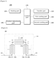
- FIG. 1 is a schematic configuration diagram of a drying device for electrode manufacturing (100, hereinafter, also referred to as 'drying device') according to one example of the present invention.
- the drying device (100) for electrode manufacturing comprises a transfer part (110), a heating part (120), a position adjustment part (140), and a first cooling part (150).
- the drying device (100) for electrode manufacturing may comprise a transfer part (110), a heating part (120), a position adjustment part (140), a first cooling part (150), and a second cooling part (160).
- Figures 2 to 4 are schematic diagrams for explaining one operating state of a drying device (100) for electrode manufacturing according to one example of the present invention. Specifically, Figure 2 shows an operating state allowing to run (also referred to as 'transfer') the electrode base material and performing a drying process, Figure 3 shows an operating state in which the running of the electrode base material is stopped during the drying process, and Figure 4 shows an operating state of the first cooling part when the running of the electrode base material is stopped.
- Figure 2 shows an operating state allowing to run (also referred to as 'transfer') the electrode base material and performing a drying process
- Figure 3 shows an operating state in which the running of the electrode base material is stopped during the drying process
- Figure 4 shows an operating state of the first cooling part when the running of the electrode base material is stopped.
- the drying device (100) comprises a transfer part (110) for transferring an electrode base material, a heating part (120: 120a, 120b) for applying heat to the electrode base material (1) under transfer, a position adjustment part (140) for adjusting a position of the heating part (120), a first cooling part (150) for spraying air toward the electrode base material (1) located on the transfer part (110), and a control part (170) for operating the first cooling part (150) when the transfer of the electrode base material (1) is stopped.
- the drying device (100) comprises a drying chamber (110).
- the drying chamber (110) has an inlet (102) through which the electrode base material (1) is input and an outlet (103) through which the electrode base material (1) finishing the drying process is discharged to the outside.
- the electrode base material (1) has a coated portion to which the electrode slurry is applied and an uncoated portion to which the electrode slurry is not applied.
- the coated portion of the electrode base material (1) may be provided on one or both sides of the electrode base material (1).
- the drying chamber (110) provides a space where the drying process of the electrode base material (1) is performed.
- a transfer part (110), a heating part (120: 120a, 120b), a position adjustment part (140), and a first cooling part (150) are disposed in the internal space of the drying chamber (110).
- the transfer part (110) may comprise a plurality of rolls (111) for running the electrode base material (1).
- the plurality of rolls (111) may be arranged in the drying chamber (110) so that the electrode base material (1) moves while changing its running direction multiple times within the drying chamber (101).
- the heating part (120) may comprise a heating lamp.
- the heating lamp may be an IR (infrared) lamp. When power is applied to the heating lamp, heat from the heating lamp is directed to the electrode base material (1), and the drying of the electrode base material (1) is performed.
- the heating part (120) may be disposed on one or both sides of the electrode base material (1) along the running direction (M) of the electrode base material (1) within the drying chamber (101).
- the heating parts (120: 120a, 120b) may be disposed on both sides (2, 3) of the electrode base material along the running direction (M) of the electrode base material (1), respectively. That is, a plurality of heating parts (120) may be provided in the drying chamber (101), and the plurality of heating parts (120) may be disposed apart from each other at a predetermined interval along the running direction (M) of the electrode base material (1).
- the heating part provided to provide heat toward a first surface (2) of the electrode base material (1) may be referred to as a first heating part (120b), and the heating part provided to provide heat toward a second surface (3) in the opposite direction of the first surface (2) of the electrode base material may be referred to as a second heating part (120a).
- the first heating part (120b) and the second heating part (120a) have the same structure, which may be distinguished depending on their positions within the drying chamber (101).
- the position adjustment part (140) is provided to move the heating part in a direction closer to or away from the electrode base material (1) located on the transfer part (110).
- the position adjustment part (140) may be configured to include a cylinder or a motor, and the like.
- the position adjustment part (140) may be controlled by the control part (170), and the position adjustment part (140) may be provided to adjust the position of the heating part (120) when transferring the electrode base material (1) in the drying chamber (101) and when the running of the electrode base material (1) is stopped.
- the position adjustment part (140) may be provided to adjust the position of the first heating part (120b) providing heat toward the first surface (2) of the electrode base material (1).
- the second heating part (120a) provided to provide heat toward the second surface (3) of the electrode base material (1) may be a position-fixed heating part
- the first heating part (120b) connected to the position adjustment part (140) may be a position-variable heating part.
- the first cooling part (150) may be provided to spray air toward the surface (one or both sides) of the electrode base material (1) located on the transfer part (110).
- the first cooling part (150) may comprise a plurality of air injection parts for spraying air toward both sides (2, 3) of the electrode base material (1) located on the transfer part, respectively.
- the plurality of air injection parts may be disposed at a predetermined interval along the running direction of the electrode base material (1) in the drying chamber (101).
- the first cooling part (150) sprays air onto the surface of the electrode base material, it may provide an air curtain preventing residual heat from being transferred from the heating parts (120: 120a, 120b) to the electrode base material.
- the first cooling part (150) may perform the function of controlling the temperature of the electrode base material by cooling the electrode base material (1), as it sprays air onto the surface of the electrode base material.
- control part (170) may move the heating part (120) in a direction away from the electrode base material (1) located on the transfer part (110) when the transfer of the electrode base material (1) is stopped.
- control part (170) may move the second heating part (120b) in a direction away from the electrode base material (1) located on the transfer part (110) when the transfer of the electrode base material (1) is stopped.
- control part (170) may stop the operation of the heating parts (120: 120a, 120b) when the transfer of the electrode base material (1) is stopped.
- control part (170) may operate the first cooling part (150) when the heating part (120b) is moved in a direction away from the electrode base material (1).
- the control part (170) stops the operation of the heating part (120).
- the control part (170) is provided so that it moves the heating part (120b) in a direction away from the electrode base material (1) located on the transfer part (110) when the transfer of the electrode base material (1) is stopped, and it operates the first cooling part (150) when the heating part (120b) moves in a direction away from the electrode base material (1).
- the first cooling part (150) sprays air onto the surface of the electrode base material (1)
- control part (170) may stop the operation of the first cooling part (150), and the control part (170) may move the heating part (120b) in a direction closer to the electrode base material (1), operate the heating part (120), and perform the drying process of the electrode base material (1).
- drying device (100) for electrode manufacturing may comprise a second cooling part (160) for cooling the heating part (120).
- Figure 5 is a schematic diagram for explaining a second cooling part (160), and Figure 6 is a schematic diagram of a heating part.
- the second cooling part (160) sprays air into the heating part (120) to perform a function of lowering the temperature of the heating part (120) in a short time.
- control part (170) may be provided to operate the second cooling part (160).
- the heating part (120b) may comprise an IR lamp (123), and a reflective member (125) for reflecting heat radiated from the IR lamp (123) to the electrode base material.
- the second cooling part (160) may be provided to spray air into a space (127) between the IR lamp (123) and the reflective member (125).
- control part (170) may control an operation of the heating lamp (123) so that the heating lamp (123) outputs in a constant wavelength range when transferring the electrode base material (1).
- control part (170) may control an operation of the heating part so that the heating part operates at a constant output value when transferring the electrode base material (1).
- the drying device for electrode manufacturing when the running of the electrode base is stopped during performing the drying process, it is possible to prevent overheating of the electrode base material due to residual heat of the heating part
Landscapes
- Engineering & Computer Science (AREA)
- Mechanical Engineering (AREA)
- General Engineering & Computer Science (AREA)
- Chemical & Material Sciences (AREA)
- Chemical Kinetics & Catalysis (AREA)
- Textile Engineering (AREA)
- Manufacturing & Machinery (AREA)
- Electrochemistry (AREA)
- General Chemical & Material Sciences (AREA)
- Life Sciences & Earth Sciences (AREA)
- Microbiology (AREA)
- Combustion & Propulsion (AREA)
- Battery Electrode And Active Subsutance (AREA)
- Drying Of Solid Materials (AREA)
Abstract
Description
- The present invention relates to a drying device for electrode manufacturing, and relates to a drying device for electrode manufacturing capable of preventing overheating of an electrode base material due to residual heat of a heating part when running of the electrode base material is stopped.
- This application claims the benefit of priority based on
Korean Patent Application No. 10-2023-0030661 dated March 8, 2023 - In lithium secondary batteries, charge and discharge are formed during a process that lithium ions moving from a positive electrode are reversibly inserted and detached to a negative electrode, and the positive electrode and the negative electrode are laminated so that a separator is interposed therebetween, thereby forming an electrode base material assembly.
- Depending on a battery case shape, the secondary batteries are classified into cylindrical batteries and rectangular batteries in which the electrode base material assembly is embedded in a cylindrical or rectangular metal can, and pouch-type batteries in which the electrode base material assembly is embedded in a pouch-type case of an aluminum laminate sheet.
- Also, the secondary battery can be formed by inserting an electrode base material assembly consisting of a positive electrode, a negative electrode, and a separator into a case and then sealing it. The electrode base material assembly can be formed by winding the positive electrode and the negative electrode in which the separator is interposed therebetween multiple times in the form of a jelly roll, or laminating them in multiple layers.
- Meanwhile, when manufacturing an electrode base material such as the positive electrode or the negative electrode in the secondary battery, a process of drying the electrode base material is performed.
- The electrode base material is dried while passing through a drying part in a roll-to-roll manner. The drying part dries the electrode base material using a heating lamp.
- Meanwhile, when the roll-to-roll equipment is stopped, there is a problem that the stopped running electrode base material in a drying chamber is overheated due to the residual heat of the heated heating lamp, and when the electrode base material is re-run in an overheated state, temperature hunting occurs, or when the temperature of the electrode base material increases, there is a problem that the physical properties of the electrode change.
- The present invention is intended to provide a drying device for electrode manufacturing capable of preventing an electrode base material from overheating due to residual heat of a heating part when running of the electrode base material is stopped.
- The present invention is intended to provide a drying device for electrode manufacturing capable of blocking residual heat of a heating part from being transferred to an electrode base material, and cooling the surface of the electrode base material, when running of the electrode base material is stopped.
- A drying device for electrode manufacturing according to one example of the present invention comprises a transfer part for transferring an electrode base material, a heating part for applying heat to the electrode base material under transfer, a position adjustment part for adjusting a position of the heating part, a first cooling part for spraying air toward the electrode base material located on the transfer part, and a control part for operating the first cooling part when the transfer of the electrode base material is stopped.
- The first cooling part may be provided to spray air toward a surface of the electrode base material located on the transfer part.
- Also, the first cooling part may comprise a plurality of air injection parts for spraying air toward both sides of the electrode base material located on the transfer part, respectively.
- In addition, the position adjustment part may be provided to move the heating part in a direction closer to or away from the electrode base material located on the transfer part.
- Furthermore, when the transfer of the electrode base material is stopped, the control part may move the heating part in the direction away from the electrode base material located on the transfer part.
- Also, the control part may stop an operation of the heating part when the transfer of the electrode base material is stopped.
- In addition, the control part may operate the first cooling part when the heating part is moved in the direction away from the electrode base material.
- Furthermore, the drying device for electrode manufacturing may further comprise a second cooling part for cooling the heating part.
- Also, the control part may be provided to operate the second cooling part when the heating part is moved in the direction away from the electrode base material.
- In addition, the heating part may comprise a heating lamp.
- Furthermore, the heating part may comprise an IR lamp, and a reflective member for reflecting heat radiated from the IR lamp to the electrode base material.
- Also, the second cooling part may be provided to spray air into a space between the IR lamp and the reflective member.
- In addition, the control part may control an operation of the heating lamp so that the heating lamp outputs in a constant wavelength range when transferring the electrode base material.
- Furthermore, the control part may control an operation of the heating part so that the heating part operates at a constant output value when transferring the electrode base material.
- In addition, the transfer part may comprise a plurality of rolls for running the electrode base material.
- As discussed above, the drying device for electrode manufacturing according to one example of the present invention has the following effects.
- When the running of the electrode base material is stopped during performing the drying process, it is possible to prevent overheating of the electrode base material due to residual heat of the heating part.
- Also, when the running of the electrode base material is stopped, it is possible to block transfer of residual heat of the heating part to the electrode base material, and it is possible to cool the surface of the electrode base material.
- In addition, when stopping and re-running the electrode base material, it is possible to prevent temperature hunting of the electrode base material, and it is possible to lower the temperature of the heating part in a short time.
-
-
Figure 1 is a schematic configuration diagram of a drying device for electrode manufacturing according to one example of the present invention. -
Figures 2 to 4 are schematic diagrams for explaining one operating state of a drying device for electrode manufacturing according to one example of the present invention. -
Figure 5 is a schematic diagram for explaining a second cooling part. -
Figure 6 is a schematic diagram of a heating part. - Hereinafter, a drying device for electrode manufacturing according to one example of the present invention will be described with reference to the accompanying drawings.
- In addition, regardless of the reference numerals, the same or corresponding components are given by the same or similar reference numerals, duplicate descriptions thereof will be omitted, and for convenience of explanation, the size and shape of each component member as shown can be exaggerated or reduced.
-
Figure 1 is a schematic configuration diagram of a drying device for electrode manufacturing (100, hereinafter, also referred to as 'drying device') according to one example of the present invention. - The drying device (100) for electrode manufacturing according to one example of the present invention comprises a transfer part (110), a heating part (120), a position adjustment part (140), and a first cooling part (150). In addition, the drying device (100) for electrode manufacturing may comprise a transfer part (110), a heating part (120), a position adjustment part (140), a first cooling part (150), and a second cooling part (160).
-
Figures 2 to 4 are schematic diagrams for explaining one operating state of a drying device (100) for electrode manufacturing according to one example of the present invention. Specifically,Figure 2 shows an operating state allowing to run (also referred to as 'transfer') the electrode base material and performing a drying process,Figure 3 shows an operating state in which the running of the electrode base material is stopped during the drying process, andFigure 4 shows an operating state of the first cooling part when the running of the electrode base material is stopped. - The drying device (100) comprises a transfer part (110) for transferring an electrode base material, a heating part (120: 120a, 120b) for applying heat to the electrode base material (1) under transfer, a position adjustment part (140) for adjusting a position of the heating part (120), a first cooling part (150) for spraying air toward the electrode base material (1) located on the transfer part (110), and a control part (170) for operating the first cooling part (150) when the transfer of the electrode base material (1) is stopped.
- The drying device (100) comprises a drying chamber (110). The drying chamber (110) has an inlet (102) through which the electrode base material (1) is input and an outlet (103) through which the electrode base material (1) finishing the drying process is discharged to the outside. The electrode base material (1) has a coated portion to which the electrode slurry is applied and an uncoated portion to which the electrode slurry is not applied. The coated portion of the electrode base material (1) may be provided on one or both sides of the electrode base material (1).
- The drying chamber (110) provides a space where the drying process of the electrode base material (1) is performed. A transfer part (110), a heating part (120: 120a, 120b), a position adjustment part (140), and a first cooling part (150) are disposed in the internal space of the drying chamber (110).
- The transfer part (110) may comprise a plurality of rolls (111) for running the electrode base material (1). The plurality of rolls (111) may be arranged in the drying chamber (110) so that the electrode base material (1) moves while changing its running direction multiple times within the drying chamber (101).
- The heating part (120) may comprise a heating lamp. In addition, the heating lamp may be an IR (infrared) lamp. When power is applied to the heating lamp, heat from the heating lamp is directed to the electrode base material (1), and the drying of the electrode base material (1) is performed.
- The heating part (120) may be disposed on one or both sides of the electrode base material (1) along the running direction (M) of the electrode base material (1) within the drying chamber (101). Referring to
Figure 2 , the heating parts (120: 120a, 120b) may be disposed on both sides (2, 3) of the electrode base material along the running direction (M) of the electrode base material (1), respectively. That is, a plurality of heating parts (120) may be provided in the drying chamber (101), and the plurality of heating parts (120) may be disposed apart from each other at a predetermined interval along the running direction (M) of the electrode base material (1). - Referring to
Figure 2 , in this document, the heating part provided to provide heat toward a first surface (2) of the electrode base material (1) may be referred to as a first heating part (120b), and the heating part provided to provide heat toward a second surface (3) in the opposite direction of the first surface (2) of the electrode base material may be referred to as a second heating part (120a). The first heating part (120b) and the second heating part (120a) have the same structure, which may be distinguished depending on their positions within the drying chamber (101). - In addition, the position adjustment part (140) is provided to move the heating part in a direction closer to or away from the electrode base material (1) located on the transfer part (110). The position adjustment part (140) may be configured to include a cylinder or a motor, and the like. The position adjustment part (140) may be controlled by the control part (170), and the position adjustment part (140) may be provided to adjust the position of the heating part (120) when transferring the electrode base material (1) in the drying chamber (101) and when the running of the electrode base material (1) is stopped.
- As one example, referring to
Figures 2 and3 , the position adjustment part (140) may be provided to adjust the position of the first heating part (120b) providing heat toward the first surface (2) of the electrode base material (1). In this structure, the second heating part (120a) provided to provide heat toward the second surface (3) of the electrode base material (1) may be a position-fixed heating part, and the first heating part (120b) connected to the position adjustment part (140) may be a position-variable heating part. - In addition, the first cooling part (150) may be provided to spray air toward the surface (one or both sides) of the electrode base material (1) located on the transfer part (110). Referring to
Figure 4 , the first cooling part (150) may comprise a plurality of air injection parts for spraying air toward both sides (2, 3) of the electrode base material (1) located on the transfer part, respectively. At this time, the plurality of air injection parts may be disposed at a predetermined interval along the running direction of the electrode base material (1) in the drying chamber (101). - As the first cooling part (150) sprays air onto the surface of the electrode base material, it may provide an air curtain preventing residual heat from being transferred from the heating parts (120: 120a, 120b) to the electrode base material. In addition, the first cooling part (150) may perform the function of controlling the temperature of the electrode base material by cooling the electrode base material (1), as it sprays air onto the surface of the electrode base material.
- Also, the control part (170) may move the heating part (120) in a direction away from the electrode base material (1) located on the transfer part (110) when the transfer of the electrode base material (1) is stopped. Referring to
Figure 3 , as one example, the control part (170) may move the second heating part (120b) in a direction away from the electrode base material (1) located on the transfer part (110) when the transfer of the electrode base material (1) is stopped. - In addition, the control part (170) may stop the operation of the heating parts (120: 120a, 120b) when the transfer of the electrode base material (1) is stopped.
- Referring to
Figures 3 and 4 , the control part (170) may operate the first cooling part (150) when the heating part (120b) is moved in a direction away from the electrode base material (1). - In summary, when the running of the electrode base material (1) in the drying chamber (101) is stopped, the control part (170) stops the operation of the heating part (120).
- However, even when the operation of the heating part (120) is stopped, the residual heat (Q) of the heating part (120) is transferred to the surface of the electrode base material (1). To prevent this, the control part (170) is provided so that it moves the heating part (120b) in a direction away from the electrode base material (1) located on the transfer part (110) when the transfer of the electrode base material (1) is stopped, and it operates the first cooling part (150) when the heating part (120b) moves in a direction away from the electrode base material (1).
- At this time, as the first cooling part (150) sprays air onto the surface of the electrode base material (1), it is possible to provide an air curtain preventing residual heat (Q) from the heating parts (120: 120a, 120b) from being transferred to the electrode base material (1), and as it simultaneously sprays air onto the surface of the electrode base material (1), it is possible to cool the electrode base material (1).
- Also, referring to
Figure 2 , when the electrode base material (1) in the drying chamber (1) is run, the control part (170) may stop the operation of the first cooling part (150), and the control part (170) may move the heating part (120b) in a direction closer to the electrode base material (1), operate the heating part (120), and perform the drying process of the electrode base material (1). - In addition, the drying device (100) for electrode manufacturing may comprise a second cooling part (160) for cooling the heating part (120).
-
Figure 5 is a schematic diagram for explaining a second cooling part (160), andFigure 6 is a schematic diagram of a heating part. - The second cooling part (160) sprays air into the heating part (120) to perform a function of lowering the temperature of the heating part (120) in a short time.
- As one example, upon stop of the running of the electrode base material, when the heating part (120b) is moved in a direction away from the electrode base material (1), the control part (170) may be provided to operate the second cooling part (160).
- Referring to
Figures 5 and 6 , the heating part (120b) may comprise an IR lamp (123), and a reflective member (125) for reflecting heat radiated from the IR lamp (123) to the electrode base material. - Also, the second cooling part (160) may be provided to spray air into a space (127) between the IR lamp (123) and the reflective member (125).
- In addition, the control part (170) may control an operation of the heating lamp (123) so that the heating lamp (123) outputs in a constant wavelength range when transferring the electrode base material (1).
- Furthermore, the control part (170) may control an operation of the heating part so that the heating part operates at a constant output value when transferring the electrode base material (1).
- The preferred examples of the present invention as described above have been disclosed for illustrative purposes, and those skilled in the art having ordinary knowledge of the present invention will be able to make various modifications, changes, and additions within the spirit and scope of the present invention, and such modifications, changes, and additions should be regarded as falling within the scope of the following claims.
- According to the drying device for electrode manufacturing according to one example of the present invention, when the running of the electrode base is stopped during performing the drying process, it is possible to prevent overheating of the electrode base material due to residual heat of the heating part
Claims (15)
- A drying device for electrode manufacturing comprising:a transfer part for transferring an electrode base material;a heating part for applying heat to the electrode base material under transfer;a position adjustment part for adjusting a position of the heating part;a first cooling part for spraying air toward the electrode base material located on the transfer part; anda control part for operating the first cooling part when the transfer of the electrode base material is stopped.
- The drying device for electrode manufacturing according to claim 1, wherein
the first cooling part is provided to spray air toward a surface of the electrode base material located on the transfer part. - The drying device for electrode manufacturing according to claim 2, wherein
the first cooling part comprises a plurality of air injection parts for spraying air toward both sides of the electrode base material located on the transfer part, respectively. - The drying device for electrode manufacturing according to claim 2, wherein
the position adjustment part moves the heating part in a direction closer to or away from the electrode base material located on the transfer part. - The drying device for electrode manufacturing according to claim 4, wherein
when the transfer of the electrode base material is stopped, the control part moves the heating part in the direction away from the electrode base material located on the transfer part. - The drying device for electrode manufacturing according to claim 5, wherein
the control part stops an operation of the heating part when the transfer of the electrode base material is stopped. - The drying device for electrode manufacturing according to claim 5, wherein
the control part operates the first cooling part when the heating part is moved in the direction away from the electrode base material. - The drying device for electrode manufacturing according to claim 5, further comprising
a second cooling part for cooling the heating part. - The drying device for electrode manufacturing according to claim 8, wherein
the control part operates the second cooling part when the heating part is moved in the direction away from the electrode base material. - The drying device for electrode manufacturing according to claim 8, wherein
the heating part comprises a heating lamp. - The drying device for electrode manufacturing according to claim 8, whereinthe heating part comprises an IR lamp, anda reflective member for reflecting heat radiated from the IR lamp to the electrode base material.
- The drying device for electrode manufacturing according to claim 11, wherein
the second cooling part is provided to spray air into a space between the IR lamp and the reflective member. - The drying device for electrode manufacturing according to claim 1, wherein
the control part controls an operation of the heating lamp so that the heating lamp outputs in a constant wavelength range when transferring the electrode base material. - The drying device for electrode manufacturing according to claim 1, wherein
the control part controls an operation of the heating part so that the heating part operates at a constant output value when transferring the electrode base material. - The drying device for electrode manufacturing according to claim 1, wherein
the transfer part comprises a plurality of rolls for running the electrode base material.
Applications Claiming Priority (2)
| Application Number | Priority Date | Filing Date | Title |
|---|---|---|---|
| KR1020230030661A KR20240137357A (en) | 2023-03-08 | 2023-03-08 | Appratus for drying electrode |
| PCT/KR2024/002484 WO2024186035A1 (en) | 2023-03-08 | 2024-02-27 | Drying device for manufacturing electrode |
Publications (2)
| Publication Number | Publication Date |
|---|---|
| EP4567914A1 true EP4567914A1 (en) | 2025-06-11 |
| EP4567914A4 EP4567914A4 (en) | 2025-12-17 |
Family
ID=92674885
Family Applications (1)
| Application Number | Title | Priority Date | Filing Date |
|---|---|---|---|
| EP24767324.7A Pending EP4567914A4 (en) | 2023-03-08 | 2024-02-27 | DRYING DEVICE FOR THE MANUFACTURING OF AN ELECTRODE |
Country Status (5)
| Country | Link |
|---|---|
| EP (1) | EP4567914A4 (en) |
| JP (1) | JP2025528271A (en) |
| KR (1) | KR20240137357A (en) |
| CN (1) | CN119923725A (en) |
| WO (1) | WO2024186035A1 (en) |
Families Citing this family (1)
| Publication number | Priority date | Publication date | Assignee | Title |
|---|---|---|---|---|
| WO2026079885A1 (en) * | 2024-10-11 | 2026-04-16 | 주식회사 엘지에너지솔루션 | Electrode drying device having novel structure |
Family Cites Families (11)
| Publication number | Priority date | Publication date | Assignee | Title |
|---|---|---|---|---|
| GB1254631A (en) * | 1968-05-15 | 1971-11-24 | Goodyear Tire & Rubber | Dryer and heater |
| JP5249916B2 (en) * | 2009-12-24 | 2013-07-31 | 三菱重工業株式会社 | Electrode dryer |
| JP5421934B2 (en) * | 2011-01-13 | 2014-02-19 | 東京エレクトロン株式会社 | Electrode manufacturing apparatus and electrode manufacturing method |
| JP5929190B2 (en) * | 2011-12-28 | 2016-06-01 | 日産自動車株式会社 | Electrode drying method and electrode drying apparatus |
| KR102306546B1 (en) * | 2018-05-23 | 2021-09-30 | 주식회사 엘지에너지솔루션 | Notching device and method for secondary battery |
| CN109365245B (en) * | 2018-10-24 | 2021-08-10 | 佛山市金银河智能装备股份有限公司 | Air-floating oven for battery pole piece |
| KR102324681B1 (en) * | 2019-08-22 | 2021-11-10 | 주식회사 스마텍 | Resdual moisture drying apparatus for battery electrode |
| KR102951962B1 (en) * | 2020-05-25 | 2026-04-10 | 주식회사 엘지에너지솔루션 | Device for drying electrode sheet and method for drying electrode sheet using the same |
| KR20230030661A (en) | 2020-07-01 | 2023-03-06 | 비전 다이아그노스틱스, 인코포레이티드 | Assay and method for measuring alkaline phosphatase activity in urine as an indicator of tissue zinc deficiency |
| CN213377612U (en) * | 2020-08-18 | 2021-06-08 | 无锡先导智能装备股份有限公司 | Heating device and roller press |
| JP7609723B2 (en) * | 2021-07-08 | 2025-01-07 | トヨタ自動車株式会社 | Heating device for electrode sheets for all-solid-state batteries |
-
2023
- 2023-03-08 KR KR1020230030661A patent/KR20240137357A/en active Pending
-
2024
- 2024-02-27 EP EP24767324.7A patent/EP4567914A4/en active Pending
- 2024-02-27 CN CN202480004133.8A patent/CN119923725A/en active Pending
- 2024-02-27 JP JP2025513099A patent/JP2025528271A/en active Pending
- 2024-02-27 WO PCT/KR2024/002484 patent/WO2024186035A1/en not_active Ceased
Also Published As
| Publication number | Publication date |
|---|---|
| KR20240137357A (en) | 2024-09-20 |
| WO2024186035A1 (en) | 2024-09-12 |
| JP2025528271A (en) | 2025-08-26 |
| EP4567914A4 (en) | 2025-12-17 |
| CN119923725A (en) | 2025-05-02 |
Similar Documents
| Publication | Publication Date | Title |
|---|---|---|
| EP3641023B1 (en) | Notching apparatus and method for secondary battery | |
| US12580173B2 (en) | Electrode plate rolling apparatus and electrode plate rolling method | |
| US12132189B2 (en) | System and method for manufacturing positive electrode for secondary battery | |
| CN104067080A (en) | Drying furnace unit and drying furnace | |
| US20230170516A1 (en) | Electrode Drying Device | |
| EP4227621B1 (en) | Drying device and electrode plate manufacturing apparatus | |
| EP4258376B1 (en) | Electrode sheet drying apparatus capable of preventing thermal wrinkles in non-coated portion | |
| KR20230146843A (en) | System for drying electrode and electrode manufacturing system | |
| KR102310909B1 (en) | Battery manufacturing system and battery manufacturing method | |
| WO2014168229A1 (en) | Drying furnace | |
| JP7646863B2 (en) | Electrode drying device and electrode manufacturing system including the same, electrode manufacturing method and electrode manufactured thereby | |
| JP2025528271A (en) | Drying equipment for electrode manufacturing | |
| KR102257677B1 (en) | Apparatus for drying the electrode plate and method for drying the same | |
| KR20220067263A (en) | Device for drying electrode compring humidifying part | |
| CN117501465A (en) | Electrode sheet drying equipment and electrode manufacturing system using the electrode sheet drying equipment | |
| EP4322240B1 (en) | Drying device with automatically adjustable shield film | |
| KR100646550B1 (en) | Electrode plate of secondary battery and electrode plate coating apparatus of secondary battery | |
| KR102675764B1 (en) | Method and equipment for manufacturing laminated film for cell type battery pouch | |
| KR102784782B1 (en) | Drying apparatus for electrode substrate of rechargeable battery | |
| JP5849875B2 (en) | Electrode manufacturing method | |
| JP2019060505A (en) | Drying method and dryer | |
| CN115997095B (en) | Electrode drying device | |
| KR20250053546A (en) | Apparatus and method for fabricating electrode of secondary battery | |
| JP7524370B1 (en) | Manufacturing method and device for laminate film for cell-type battery pouch | |
| EP4636832A1 (en) | Electrode manufacturing system, electrode manufacturing method, and electrode |
Legal Events
| Date | Code | Title | Description |
|---|---|---|---|
| STAA | Information on the status of an ep patent application or granted ep patent |
Free format text: STATUS: THE INTERNATIONAL PUBLICATION HAS BEEN MADE |
|
| PUAI | Public reference made under article 153(3) epc to a published international application that has entered the european phase |
Free format text: ORIGINAL CODE: 0009012 |
|
| STAA | Information on the status of an ep patent application or granted ep patent |
Free format text: STATUS: REQUEST FOR EXAMINATION WAS MADE |
|
| 17P | Request for examination filed |
Effective date: 20250307 |
|
| AK | Designated contracting states |
Kind code of ref document: A1 Designated state(s): AL AT BE BG CH CY CZ DE DK EE ES FI FR GB GR HR HU IE IS IT LI LT LU LV MC ME MK MT NL NO PL PT RO RS SE SI SK SM TR |
|
| A4 | Supplementary search report drawn up and despatched |
Effective date: 20251114 |
|
| RIC1 | Information provided on ipc code assigned before grant |
Ipc: H01M 4/04 20060101AFI20251110BHEP Ipc: F26B 13/10 20060101ALI20251110BHEP Ipc: F26B 21/00 20060101ALI20251110BHEP Ipc: F26B 3/30 20060101ALI20251110BHEP Ipc: F26B 21/06 20060101ALI20251110BHEP Ipc: H05B 3/00 20060101ALI20251110BHEP |
|
| STAA | Information on the status of an ep patent application or granted ep patent |
Free format text: STATUS: EXAMINATION IS IN PROGRESS |
|
| 17Q | First examination report despatched |
Effective date: 20260331 |