EP4567445A1 - Verfahren und vorrichtung zur schätzung des ladezustands einer batterie in einem batteriesystem - Google Patents
Verfahren und vorrichtung zur schätzung des ladezustands einer batterie in einem batteriesystem Download PDFInfo
- Publication number
- EP4567445A1 EP4567445A1 EP23849039.5A EP23849039A EP4567445A1 EP 4567445 A1 EP4567445 A1 EP 4567445A1 EP 23849039 A EP23849039 A EP 23849039A EP 4567445 A1 EP4567445 A1 EP 4567445A1
- Authority
- EP
- European Patent Office
- Prior art keywords
- battery
- state
- charge
- main circuit
- replacement module
- Prior art date
- Legal status (The legal status is an assumption and is not a legal conclusion. Google has not performed a legal analysis and makes no representation as to the accuracy of the status listed.)
- Pending
Links
Images


Classifications
-
- G—PHYSICS
- G01—MEASURING; TESTING
- G01R—MEASURING ELECTRIC VARIABLES; MEASURING MAGNETIC VARIABLES
- G01R31/00—Arrangements for testing electric properties; Arrangements for locating electric faults; Arrangements for electrical testing characterised by what is being tested not provided for elsewhere
- G01R31/36—Arrangements for testing, measuring or monitoring the electrical condition of accumulators or electric batteries, e.g. capacity or state of charge [SoC]
- G01R31/385—Arrangements for measuring battery or accumulator variables
- G01R31/387—Determining ampere-hour charge capacity or SoC
- G01R31/388—Determining ampere-hour charge capacity or SoC involving voltage measurements
-
- H—ELECTRICITY
- H01—ELECTRIC ELEMENTS
- H01M—PROCESSES OR MEANS, e.g. BATTERIES, FOR THE DIRECT CONVERSION OF CHEMICAL ENERGY INTO ELECTRICAL ENERGY
- H01M4/00—Electrodes
- H01M4/02—Electrodes composed of, or comprising, active material
- H01M4/36—Selection of substances as active materials, active masses, active liquids
- H01M4/58—Selection of substances as active materials, active masses, active liquids of inorganic compounds other than oxides or hydroxides, e.g. sulfides, selenides, tellurides, halogenides or LiCoFy; of polyanionic structures, e.g. phosphates, silicates or borates
- H01M4/5825—Oxygenated metallic salts or polyanionic structures, e.g. borates, phosphates, silicates, olivines
-
- G—PHYSICS
- G01—MEASURING; TESTING
- G01R—MEASURING ELECTRIC VARIABLES; MEASURING MAGNETIC VARIABLES
- G01R31/00—Arrangements for testing electric properties; Arrangements for locating electric faults; Arrangements for electrical testing characterised by what is being tested not provided for elsewhere
- G01R31/36—Arrangements for testing, measuring or monitoring the electrical condition of accumulators or electric batteries, e.g. capacity or state of charge [SoC]
- G01R31/3644—Constructional arrangements
-
- G—PHYSICS
- G01—MEASURING; TESTING
- G01R—MEASURING ELECTRIC VARIABLES; MEASURING MAGNETIC VARIABLES
- G01R31/00—Arrangements for testing electric properties; Arrangements for locating electric faults; Arrangements for electrical testing characterised by what is being tested not provided for elsewhere
- G01R31/36—Arrangements for testing, measuring or monitoring the electrical condition of accumulators or electric batteries, e.g. capacity or state of charge [SoC]
- G01R31/367—Software therefor, e.g. for battery testing using modelling or look-up tables
-
- G—PHYSICS
- G01—MEASURING; TESTING
- G01R—MEASURING ELECTRIC VARIABLES; MEASURING MAGNETIC VARIABLES
- G01R31/00—Arrangements for testing electric properties; Arrangements for locating electric faults; Arrangements for electrical testing characterised by what is being tested not provided for elsewhere
- G01R31/36—Arrangements for testing, measuring or monitoring the electrical condition of accumulators or electric batteries, e.g. capacity or state of charge [SoC]
- G01R31/378—Arrangements for testing, measuring or monitoring the electrical condition of accumulators or electric batteries, e.g. capacity or state of charge [SoC] specially adapted for the type of battery or accumulator
-
- G—PHYSICS
- G01—MEASURING; TESTING
- G01R—MEASURING ELECTRIC VARIABLES; MEASURING MAGNETIC VARIABLES
- G01R31/00—Arrangements for testing electric properties; Arrangements for locating electric faults; Arrangements for electrical testing characterised by what is being tested not provided for elsewhere
- G01R31/36—Arrangements for testing, measuring or monitoring the electrical condition of accumulators or electric batteries, e.g. capacity or state of charge [SoC]
- G01R31/385—Arrangements for measuring battery or accumulator variables
- G01R31/387—Determining ampere-hour charge capacity or SoC
-
- G—PHYSICS
- G01—MEASURING; TESTING
- G01R—MEASURING ELECTRIC VARIABLES; MEASURING MAGNETIC VARIABLES
- G01R31/00—Arrangements for testing electric properties; Arrangements for locating electric faults; Arrangements for electrical testing characterised by what is being tested not provided for elsewhere
- G01R31/36—Arrangements for testing, measuring or monitoring the electrical condition of accumulators or electric batteries, e.g. capacity or state of charge [SoC]
- G01R31/392—Determining battery ageing or deterioration, e.g. state of health
-
- G—PHYSICS
- G01—MEASURING; TESTING
- G01R—MEASURING ELECTRIC VARIABLES; MEASURING MAGNETIC VARIABLES
- G01R31/00—Arrangements for testing electric properties; Arrangements for locating electric faults; Arrangements for electrical testing characterised by what is being tested not provided for elsewhere
- G01R31/36—Arrangements for testing, measuring or monitoring the electrical condition of accumulators or electric batteries, e.g. capacity or state of charge [SoC]
- G01R31/396—Acquisition or processing of data for testing or for monitoring individual cells or groups of cells within a battery
-
- H—ELECTRICITY
- H01—ELECTRIC ELEMENTS
- H01M—PROCESSES OR MEANS, e.g. BATTERIES, FOR THE DIRECT CONVERSION OF CHEMICAL ENERGY INTO ELECTRICAL ENERGY
- H01M10/00—Secondary cells; Manufacture thereof
- H01M10/42—Methods or arrangements for servicing or maintenance of secondary cells or secondary half-cells
- H01M10/4285—Testing apparatus
-
- H—ELECTRICITY
- H01—ELECTRIC ELEMENTS
- H01M—PROCESSES OR MEANS, e.g. BATTERIES, FOR THE DIRECT CONVERSION OF CHEMICAL ENERGY INTO ELECTRICAL ENERGY
- H01M10/00—Secondary cells; Manufacture thereof
- H01M10/42—Methods or arrangements for servicing or maintenance of secondary cells or secondary half-cells
- H01M10/48—Accumulators combined with arrangements for measuring, testing or indicating the condition of cells, e.g. the level or density of the electrolyte
-
- Y—GENERAL TAGGING OF NEW TECHNOLOGICAL DEVELOPMENTS; GENERAL TAGGING OF CROSS-SECTIONAL TECHNOLOGIES SPANNING OVER SEVERAL SECTIONS OF THE IPC; TECHNICAL SUBJECTS COVERED BY FORMER USPC CROSS-REFERENCE ART COLLECTIONS [XRACs] AND DIGESTS
- Y02—TECHNOLOGIES OR APPLICATIONS FOR MITIGATION OR ADAPTATION AGAINST CLIMATE CHANGE
- Y02E—REDUCTION OF GREENHOUSE GAS [GHG] EMISSIONS, RELATED TO ENERGY GENERATION, TRANSMISSION OR DISTRIBUTION
- Y02E60/00—Enabling technologies; Technologies with a potential or indirect contribution to GHG emissions mitigation
- Y02E60/10—Energy storage using batteries
Definitions
- the present disclosure relates to battery technology, and in particular to a method and device for estimating the state of charge of a battery in a battery system.
- the Chinese invention patent document with the publication number CN114545256A discloses a method and system for estimating the state of charge of a lithium iron phosphate battery, in which a replacement module with a larger capacity than the main circuit battery is used to replace one of the original batteries in the main circuit, and the state of charge of the replacement module is noted as X.
- the state of charge of the battery in the replacement module and the main circuit is adjusted so that the two are consistent at 0% SOC, and according to the series relationship, in the subsequent charging and discharging process, the estimated state of charge of the main circuit is X*A/B, wherein the A is the capacity of the replacement module, and the B is the capacity of the battery in the main circuit.
- the battery voltage varies more obviously with the state of charge in the interval of 0% ⁇ 30% SOC and the interval of 90% ⁇ 100% SOC, which can be used to estimate the state of charge.
- the purpose of the present disclosure is to provide a method and device for estimating the state of charge of a battery in a battery system, which solves the problem of inaccurate estimation result of the state of charge of the lithium iron phosphate battery in the prior art.
- the present disclosure provides a method for estimating a state of charge of a battery in a battery system, wherein comprising at least the following steps:
- conducting self-discharge detection on the replacement module and the main circuit battery according to the state of charge of the replacement module and the main circuit battery comprises: Conducting self-discharge detection when both the state of charge of the replacement module and the state of charge of the main circuit battery are in an interval of low state of charge or when the state of charge of the main circuit battery is in an interval of high state of charge.
- the interval of low state of charge is 0% ⁇ 30%, and the interval of high state of charge is 90% ⁇ 100%.
- the performing balance control on the replacement module and the main circuit battery comprises: transferring a portion of a battery energy with a small amount of self-discharge in the replacement module or the main circuit battery to a battery with a large amount of self-discharge.
- the performing balance control on the replacement module and the main circuit battery comprises: consuming a battery energy with a small amount of self-discharge in the replacement module or the main circuit battery through resistance.
- the conducting self-discharge detection on the replacement module and the main circuit battery according to the state of charge and a state of health of battery of the replacement module and the main circuit battery respectively, further comprises: Determining a state of health of battery of the replacement module and a state of health of battery of the main circuit battery.
- the self-discharge detection determining that a large amount of self-discharge occurs in the replacement module or the main circuit battery if the state of charge of the main circuit battery is not equal to n times the state of charge of the replacement module; wherein the n is the ratio of the current capacity of the replacement module to the current capacity C2 of the main circuit battery, wherein the current capacity of the replacement module is a product of an original capacity of the replacement module and the state of health of battery of the replacement module, and the current capacity of the main circuit battery is a product of an original capacity of the main circuit battery and the state of health of battery of the main circuit battery.
- a result of the balance control makes the state of charge of the main circuit battery equal to n times the state of charge of the replacement module.
- the present disclosure also provides a device for estimating a state of charge of a battery in a battery system, wherein comprising a memory, a processor, and a program stored in the memory and runnable on the processor, wherein the processor executing the program to implement the steps of the method for estimating a state of charge of a battery in a battery system as described above.
- the method for estimating the state of charge of a battery in a battery system of the present disclosure carries out self-discharge detection and balance control on the existing estimated state of charge, the state of charge of the main circuit battery is estimated and obtained by the updated state of charge after the balance control, avoids the interference caused by the large amount of self-discharge of the replacement module or the main circuit battery, improves the accuracy of the estimation of the state of charge of the main circuit battery, and also expands the estimation interval of the state of charge SOC of the main circuit battery, which further improves the stability of the battery system.
- FIG. 1 to FIG. 3 Please refer to FIG. 1 to FIG. 3 .
- the drawings provided in the embodiment only illustrate the basic concept of the present disclosure in a schematic manner. Therefore, the drawings only show the components related to the present disclosure and are not drawn according to the number, the shape, and the size of the components in actual implementation.
- the form, the number, and the proportion of each component in actual implementation can be an arbitrary change, and the layout of the components may also be more complex.
- FIG. 1 it is a schematic diagram of the variation of 0.1C charging voltage curve of a lithium iron phosphate battery at 25°C.
- the variation of voltage with SOC is not obvious in the interval of state of charge 30% ⁇ 90% SOC, which increases the difficulty of SOC estimation; while in the detection interval of the state of charge 0% ⁇ 30% SOC and 90% ⁇ 100% SOC, the variation of voltage with the state of charge is more obvious. Therefore, the estimation of the state of charge can be carried out by voltage characteristics in the two intervals, and the estimation result is more accurate.
- the present disclosure in order to solve the technical defect of the prior art that when there is a large amount of self-discharge in the replacement module or the main circuit batteries, it will cause a large error in the estimation of the state of charge, which will further lead to an inaccurate estimation result of the state of charge of the lithium iron phosphate battery.
- the present disclosure proposes to add the means of the self-discharge detection and the balance control in the case of low state of charge (i.e., the state of charge of the replacement module and the state of charge of the main circuit battery are both less than 30%) and in the case of high state of charge (i.e., the state of charge of the main circuit battery is greater than 90%), thereby improving the accuracy of estimation of the state of charge of the lithium iron phosphate battery and expanding the estimation interval of the state of charge of the lithium iron phosphate battery, and further improving the stability of the battery system.
- low state of charge i.e., the state of charge of the replacement module and the state of charge of the main circuit battery are both less than 30%
- high state of charge i.e., the state of charge of the main circuit battery is greater than 90%
- the present disclosure proposes a method for estimating a state of charge of a battery in a battery system, as shown in FIG. 2 , comprising at least:
- the original capacity of the replacement module is C1' and the original capacity of the main circuit battery is C2', wherein C1'/C2'> 1.
- the original battery and the main circuit battery are identical.
- the replacement module of the present disclosure is a replacement battery, and the replacement battery may be a lithium iron phosphate battery with greater difference than the original battery capacity and higher capacity than the original battery.
- the present disclosure uses a proportional conversion method to estimate and obtain the state of charge of the main circuit battery according to the state of charge of the replacement battery. Specifically, converting the state of charge of the replacement battery to the state of charge of the main circuit battery using the proportional conversion method.
- the larger the difference between the capacity of the replacement battery and the capacity of the main circuit battery the wider the interval segment for estimating the state of charge.
- the larger the difference between the capacity of the replacement battery and the capacity of the main circuit battery the more accurate the estimation will be, but if the difference is too large, it will lead to a waste of cost, which makes it impossible to be applied in practice.
- the number of the original battery and the number of the replacement battery in the replacement module are not limited, and the number of the original battery and the number of the replacement battery in the replacement module may be the same or different.
- the number may be one or multiple, but when the number is multiple, the multiple original batteries may be connected in series or parallel, and the replacement batteries in the replacement module may be connected in series or parallel, as long as it is satisfied that the capacity of the battery in the replacement module is larger than the capacity of the original battery.
- the present disclosure uses the proportional conversion method to estimate and obtain the state of charge of the main circuit battery according to the state of charge of the replacement battery. Therefore, it is necessary to first obtain the state of charge of the replacement module and determine the proportional conversion method.
- the state of charge of the replacement module and the state of charge of the main circuit battery are consistent at 0% SOC.
- the replacement module is the lithium iron phosphate battery, and the original capacity C1' of the replacement battery is twice the original capacity C2' of the main circuit battery.
- the n' may also be a value of 1.5, 3, 4, etc.
- both the replacement battery and the main circuit battery are in the 0% SOC state. Since the two are connected in series, the subsequent charging and discharging process flow the same current through the two, so when the state of charge of the main circuit battery varies in 0% ⁇ 100%, the state of charge of the replacement battery is just half of the state of charge of the main circuit battery, i.e., 0% ⁇ 50%.
- the SOC of the replacement battery can be estimated more accurately by the voltage and the SOC (0% ⁇ 60% SOC) of the main circuit battery can be obtained. In other intervals (e.g., the 90% ⁇ 100% SOC interval of the lithium iron phosphate battery), the estimated SOC of the main circuit battery is still used.
- the state of charge SOC_T of the replacement battery is at 0% ⁇ 30% SOC
- the state of charge SOC_X of the main circuit battery is 2 ⁇ SOC_T and is estimated more accurately.
- the state of charge of the main circuit battery at 0% ⁇ 60% SOC can be estimated accurately, while the 90% ⁇ 100% SOC interval segment is still estimated by using the voltage of the main circuit for the SOC estimation. Therefore, the embodiment of the present disclosure can extend the accurate segment of the state of charge estimated by the voltage from 0% ⁇ 30%SOC and 90% ⁇ 100%SOC to 0% ⁇ 60%SOC and 90% ⁇ 100%SOC.
- the embodiment of the present disclosure is only used as an example and is not limited to it.
- the current capacity of the replacement module is the product of the original capacity C1' of the replacement module and the state of health of battery SOH1 of the replacement module
- the current capacity of the main circuit battery is the product of the original capacity C2' of the main circuit battery and the state of health of battery SOH2 of the main circuit battery, wherein C1'> C2'.
- the present disclosure updates the current capacity of the replacement module and the current capacity of the main circuit battery by the state of health of battery, then re-determines a new equilibrium relationship between the state of charge of the main circuit battery and the state of charge of the replacement module, and finally determines according to the new equilibrium relationship, which improves the accuracy of the determination of large amount of self-discharge.
- the interval of low state of charge is 0% ⁇ 30%, and the interval of high state of charge is 90% ⁇ 100%.
- the state of charge of the replacement module is estimated and obtained according to the voltage of the replacement module or the ampere-time integration method, and the state of charge of the main circuit battery is estimated and obtained according to the voltage of the main circuit battery.
- the state of charge SOC_X of the main circuit battery estimated according to the voltage is less than 30%
- the state of charge SOC_T of the replacement module estimated according to the voltage is less than 30%.
- SOC_X>n ⁇ SOC_T it is determined that a large amount of self-discharge has occurred in the replacement module. If SOC_X ⁇ n ⁇ SOC_T, then it is determined that a large amount of self-discharge has occurred in the main circuit battery.
- the state of charge SOC_X of the main circuit battery estimated according to the voltage is greater than 90% and the state of charge of the replacement module is less than 50%.
- SOC_X If SOC_X>n ⁇ SOC_T, then it is determined that a large amount of self-discharge has occurred in the replacement module. If SOC_X ⁇ n ⁇ SOC_T, then it is determined that a large amount of self-discharge has occurred in the main circuit battery.
- the characteristic curve of the voltage and the state of charge it can be seen that the variation of the voltage with the SOC is not obvious between 30% ⁇ 60%, so the estimation of the SOC according to the voltage may be prone to a large deviation, and therefore, the state of charge can be estimated and obtained according to other methods in the prior art, such as the ampere-time integration method.
- the absolute balance cannot be stably maintained during the balance control process, therefore, in practical application, based on the determination condition in the embodiments of the present disclosure, a certain degree of deviation can be allowed to determine the existence of large amount of self-discharge, wherein the deviation can be the magnitude of the deviation (single value or interval), or a certain proportional value.
- the balance control of the present disclosure is either active balance or passive balance.
- the active balance means transferring a portion of the battery energy with a small amount of self-discharge in the replacement module or the main circuit battery to a battery with a large amount of self-discharge, and the passive balance means consuming the battery energy with a small amount of self-discharge in the replacement module or the main circuit battery through resistance.
- the present disclosure readjusts the relationship between the state of charge of the replacement module and the state of charge of the main circuit battery by balance control, thereby ensuring the accuracy of the state of charge of the main circuit battery obtained according to the updated state of charge of the replacement module.
- step S1 After carrying out balance control to the battery in the lithium iron phosphate battery branch of the battery system, the updated state of charge of the replacement module is determined. Then, the method of step S1 is adopted, i.e., using a proportional conversion method to estimate and obtain the updated state of charge of the main circuit battery according to the updated state of charge of the replacement module. By updating the state of charge of the main circuit battery through the updated state of charge of the main circuit battery, a more accurate state of charge of the main circuit is obtained.
- the updated state of charge the replacement module is determined as follows: when the state of charge of the replacement module is not changed during the balance control process, the updated state of charge is the original state of charge, and when the state of charge of the replacement module is changed during the balance control process, it is necessary to reacquire or calculate the state of charge of the replacement module to determine the updated state of charge.
- the time of the balance control is a little long, the state of charge of the replacement module will be changed regardless of whether it is used as the controlled balance object, and at this time, the updated state of charge the replacement module is always the state of charge to be reacquired.
- the updated state of charge of the main circuit battery is estimated and obtained using a proportional conversion method according to the updated state of charge of the replacement module, the updated state of charge of the main circuit battery is used as the state of charge of the main circuit battery, and the state of charge of the main circuit battery is estimated and obtained by the updated state of charge after the balance control.
- the method avoids interference caused by the large amount of self-discharge in the replacement module or the main circuit battery, improves the accuracy of estimating the state of charge of the main circuit battery, expands the estimation interval of the state of charge SOC of the main circuit battery, and further improves the stability of the battery system.
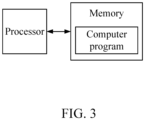
- the present disclosure also provides a schematic diagram of the structure of a device for estimating the state of charge of a battery in a battery system as shown in FIG. 3 , wherein comprising the memory, the processor, and the program stored in the memory and runnable on the processor, wherein the processor executing the program to implement the steps of the method for estimating a state of charge of a battery in a battery system as described above.
- the present disclosure comprises the method and device for estimating the state of charge of a battery in a battery system, wherein the method for estimating a state of charge of a battery in a battery system carries out the self-discharge detection and the balance control of the existing estimated state of charge, and the state of charge of the main circuit battery is estimated and obtained by the updated state of charge after the balance control, avoids interference caused by the large amount of self-discharge in the replacement module or the main circuit battery, further improves the accuracy of estimating the state of charge of the main circuit battery, also expands the estimation interval of the state of charge SOC of the main circuit battery, and further improves the stability of the battery system. Therefore, the present disclosure effectively overcomes the shortcomings of the prior art and has high industrial utilization value.
Landscapes
- Physics & Mathematics (AREA)
- General Physics & Mathematics (AREA)
- Chemical & Material Sciences (AREA)
- Chemical Kinetics & Catalysis (AREA)
- Electrochemistry (AREA)
- General Chemical & Material Sciences (AREA)
- Crystallography & Structural Chemistry (AREA)
- Inorganic Chemistry (AREA)
- Engineering & Computer Science (AREA)
- Manufacturing & Machinery (AREA)
- Secondary Cells (AREA)
- Tests Of Electric Status Of Batteries (AREA)
Priority Applications (1)
| Application Number | Priority Date | Filing Date | Title |
|---|---|---|---|
| MA71701A MA71701A (fr) | 2022-08-02 | 2023-06-05 | Procédé et dispositif d'estimation d'état de charge de batterie dans un système de batterie |
Applications Claiming Priority (2)
| Application Number | Priority Date | Filing Date | Title |
|---|---|---|---|
| CN202210923233.3A CN115343640B (zh) | 2022-08-02 | 2022-08-02 | 电池系统中电池荷电状态的估算方法及装置 |
| PCT/CN2023/098427 WO2024027329A1 (zh) | 2022-08-02 | 2023-06-05 | 电池系统中电池荷电状态的估算方法及装置 |
Publications (1)
| Publication Number | Publication Date |
|---|---|
| EP4567445A1 true EP4567445A1 (de) | 2025-06-11 |
Family
ID=83949859
Family Applications (1)
| Application Number | Title | Priority Date | Filing Date |
|---|---|---|---|
| EP23849039.5A Pending EP4567445A1 (de) | 2022-08-02 | 2023-06-05 | Verfahren und vorrichtung zur schätzung des ladezustands einer batterie in einem batteriesystem |
Country Status (7)
| Country | Link |
|---|---|
| US (1) | US20260043862A1 (de) |
| EP (1) | EP4567445A1 (de) |
| JP (1) | JP2025525135A (de) |
| KR (1) | KR20250044365A (de) |
| CN (1) | CN115343640B (de) |
| MA (1) | MA71701A (de) |
| WO (1) | WO2024027329A1 (de) |
Families Citing this family (2)
| Publication number | Priority date | Publication date | Assignee | Title |
|---|---|---|---|---|
| CN115343640B (zh) * | 2022-08-02 | 2025-09-12 | 瑞浦兰钧能源股份有限公司 | 电池系统中电池荷电状态的估算方法及装置 |
| CN116413612A (zh) * | 2023-04-17 | 2023-07-11 | 上海瑞浦青创新能源有限公司 | 一种双体系电池包的荷电状态估计方法及装置 |
Family Cites Families (25)
| Publication number | Priority date | Publication date | Assignee | Title |
|---|---|---|---|---|
| JP4089691B2 (ja) * | 2004-02-03 | 2008-05-28 | 株式会社デンソー | 車両用電池の制御装置 |
| KR101486810B1 (ko) * | 2010-04-02 | 2015-02-03 | 에스케이이노베이션 주식회사 | 착탈 가능한 배터리 스트링을 위한 전하 균일 장치 |
| JP5395006B2 (ja) * | 2010-07-22 | 2014-01-22 | 株式会社日立製作所 | 電池制御システムとその制御方法並びに電池システム |
| CN102088118B (zh) * | 2010-12-28 | 2013-09-18 | 深圳市航盛电子股份有限公司 | 一种电池管理系统、电动车及荷电状态的估算方法 |
| CN102355031B (zh) * | 2011-10-29 | 2014-05-14 | 重庆大学 | 一种磷酸铁锂动力电池组主动均衡充电方法 |
| US9077181B2 (en) * | 2013-01-11 | 2015-07-07 | GM Global Technology Operations LLC | Battery section balancing methods and systems |
| DE102013204346A1 (de) * | 2013-03-13 | 2014-09-18 | Robert Bosch Gmbh | Balancing bei der Reparatur von Batteriepacks |
| DE102014220005A1 (de) * | 2014-10-02 | 2016-04-07 | Robert Bosch Gmbh | Verfahren für eine Zellsymmetrierung einer Mehrzahl von Batteriezellen und Batteriesystem zum Durchführen eines derartigen Verfahrens |
| CN105633487B (zh) * | 2016-01-13 | 2018-04-06 | 河南理工大学 | 一种锂离子电池智能管理系统 |
| JP6566136B2 (ja) * | 2016-06-22 | 2019-08-28 | 株式会社村田製作所 | 組電池回路、容量係数検出方法、および容量係数検出プログラム |
| CN109463022B (zh) * | 2016-07-13 | 2022-05-06 | 株式会社村田制作所 | 电池组电路、容量系数检测方法以及存储介质 |
| CN106125003B (zh) * | 2016-08-27 | 2018-10-19 | 上海交通大学 | 一种串联型电池组的状态估计装置和方法 |
| CN106443480B (zh) * | 2016-11-04 | 2019-11-22 | 天津市捷威动力工业有限公司 | 一种锂离子电池系统soc估算方法 |
| CN106646243A (zh) * | 2016-11-09 | 2017-05-10 | 珠海格力电器股份有限公司 | 一种蓄电池荷电状态计算方法和装置 |
| CN108206560B (zh) * | 2016-12-20 | 2021-01-19 | 宁德时代新能源科技股份有限公司 | 电池均衡方法 |
| JP6969307B2 (ja) * | 2017-11-14 | 2021-11-24 | 株式会社Gsユアサ | 管理装置、蓄電システム、蓄電素子の残存容量を均等化する方法、蓄電素子の内部状態を推定する方法 |
| CN108008317A (zh) * | 2017-12-01 | 2018-05-08 | 重庆大学 | 一种基于电池开路电压曲线特性的荷电状态估计方法 |
| CN109256834B (zh) * | 2018-10-12 | 2020-11-24 | 华南理工大学 | 基于电池健康状态和荷电状态的电池组主动均衡方法 |
| CN110231572A (zh) * | 2019-06-14 | 2019-09-13 | 安徽锐能科技有限公司 | 一种基于电池主动均衡的soc估计装置 |
| CN113376532A (zh) * | 2020-02-25 | 2021-09-10 | 北京新能源汽车股份有限公司 | 一种电池组均衡模块的检测方法、装置及系统 |
| CN112789780A (zh) * | 2020-04-26 | 2021-05-11 | 深圳市大疆创新科技有限公司 | 电池的均衡方法、智能电池、充电系统及存储介质 |
| CN112397798B (zh) * | 2020-11-13 | 2022-04-26 | 上汽大众汽车有限公司 | 一种动力电池管理系统及匹配方法 |
| CN112599932A (zh) * | 2021-01-08 | 2021-04-02 | 蔚来汽车科技(安徽)有限公司 | 电池包、方法和车辆 |
| CN114545256B (zh) * | 2022-01-26 | 2026-02-27 | 上海瑞浦青创新能源有限公司 | 磷酸铁锂电池荷电状态的估算方法及系统 |
| CN115343640B (zh) * | 2022-08-02 | 2025-09-12 | 瑞浦兰钧能源股份有限公司 | 电池系统中电池荷电状态的估算方法及装置 |
-
2022
- 2022-08-02 CN CN202210923233.3A patent/CN115343640B/zh active Active
-
2023
- 2023-06-05 US US19/100,270 patent/US20260043862A1/en active Pending
- 2023-06-05 JP JP2025505596A patent/JP2025525135A/ja active Pending
- 2023-06-05 WO PCT/CN2023/098427 patent/WO2024027329A1/zh not_active Ceased
- 2023-06-05 MA MA71701A patent/MA71701A/fr unknown
- 2023-06-05 KR KR1020257006375A patent/KR20250044365A/ko active Pending
- 2023-06-05 EP EP23849039.5A patent/EP4567445A1/de active Pending
Also Published As
| Publication number | Publication date |
|---|---|
| CN115343640A (zh) | 2022-11-15 |
| WO2024027329A1 (zh) | 2024-02-08 |
| JP2025525135A (ja) | 2025-08-01 |
| US20260043862A1 (en) | 2026-02-12 |
| CN115343640B (zh) | 2025-09-12 |
| MA71701A (fr) | 2025-05-30 |
| KR20250044365A (ko) | 2025-03-31 |
Similar Documents
| Publication | Publication Date | Title |
|---|---|---|
| EP4567445A1 (de) | Verfahren und vorrichtung zur schätzung des ladezustands einer batterie in einem batteriesystem | |
| Xiong et al. | Model-based state of charge and peak power capability joint estimation of lithium-ion battery in plug-in hybrid electric vehicles | |
| CN116008827B (zh) | 一种锂离子电池析锂电位的确定方法、装置及电子设备 | |
| Xiong et al. | A data-driven adaptive state of charge and power capability joint estimator of lithium-ion polymer battery used in electric vehicles | |
| JP6171897B2 (ja) | 近似関数作成プログラム、近似関数作成方法、近似関数作成装置および充電率推定プログラム | |
| US11316212B2 (en) | Method, system and device for active balance control of battery pack | |
| CA2861528A1 (en) | Open-circuit voltage estimation device, power storage apparatus, and open-circuit voltage estimation method | |
| JP2015215169A (ja) | パラメータ算出装置、パラメータ算出方法及びプログラム | |
| CN114200315B (zh) | 剩余充电时间的预测方法、装置、电子设备和存储介质 | |
| CN118690704B (zh) | 锂电池等效电路模型参数在线自适应调节方法及相关装置 | |
| CN118690705B (zh) | 锂电池等效电路模型参数在线自适应调节方法及相关装置 | |
| CN106019159A (zh) | 锂电池健康状态的预估更新方法 | |
| CN114062933B (zh) | 电池soc的修正方法、装置、计算机存储介质及处理器 | |
| KR20200107411A (ko) | 배터리 soh 추정 방법 및 이를 적용한 배터리 팩 | |
| CN113391225A (zh) | 一种考虑容量退化的锂电池荷电状态估计方法 | |
| CN105974328A (zh) | 二次电池的实际容量的测量方法和装置、无人机 | |
| CN115236517B (zh) | 锂电池soc估计方法、设备、存储介质及装置 | |
| CN118425794A (zh) | 单体电池的健康度的估算方法、装置及设备 | |
| Kim et al. | A real-time condition monitoring for lithium-ion batteries using a low-price microcontroller | |
| CN119689265A (zh) | 基于工商业储能的荷电状态的计算方法、储能系统、设备 | |
| CN116749813B (zh) | 燃料电池充电系统调节方法、装置、设备和介质 | |
| Li et al. | A new method to estimate the state of charge of the green battery | |
| CN119024207A (zh) | 电池包的健康状态的检测方法、装置和系统 | |
| JP7188327B2 (ja) | 電池状態推定装置 | |
| CN114825407B (zh) | 一种双向变换器的充放电切换方法、装置、系统及介质 |
Legal Events
| Date | Code | Title | Description |
|---|---|---|---|
| STAA | Information on the status of an ep patent application or granted ep patent |
Free format text: STATUS: THE INTERNATIONAL PUBLICATION HAS BEEN MADE |
|
| PUAI | Public reference made under article 153(3) epc to a published international application that has entered the european phase |
Free format text: ORIGINAL CODE: 0009012 |
|
| STAA | Information on the status of an ep patent application or granted ep patent |
Free format text: STATUS: REQUEST FOR EXAMINATION WAS MADE |
|
| 17P | Request for examination filed |
Effective date: 20250226 |
|
| AK | Designated contracting states |
Kind code of ref document: A1 Designated state(s): AL AT BE BG CH CY CZ DE DK EE ES FI FR GB GR HR HU IE IS IT LI LT LU LV MC ME MK MT NL NO PL PT RO RS SE SI SK SM TR |
|
| DAX | Request for extension of the european patent (deleted) | ||
| RAV | Requested validation state of the european patent: fee paid |
Extension state: MA Effective date: 20250226 |