EP4567367A1 - Phasenwechselmaterial-wärmetauscher - Google Patents
Phasenwechselmaterial-wärmetauscher Download PDFInfo
- Publication number
- EP4567367A1 EP4567367A1 EP24215222.1A EP24215222A EP4567367A1 EP 4567367 A1 EP4567367 A1 EP 4567367A1 EP 24215222 A EP24215222 A EP 24215222A EP 4567367 A1 EP4567367 A1 EP 4567367A1
- Authority
- EP
- European Patent Office
- Prior art keywords
- phase change
- heat exchanger
- change elements
- outer housing
- change element
- Prior art date
- Legal status (The legal status is an assumption and is not a legal conclusion. Google has not performed a legal analysis and makes no representation as to the accuracy of the status listed.)
- Pending
Links
Images




Classifications
-
- F—MECHANICAL ENGINEERING; LIGHTING; HEATING; WEAPONS; BLASTING
- F28—HEAT EXCHANGE IN GENERAL
- F28D—HEAT-EXCHANGE APPARATUS, NOT PROVIDED FOR IN ANOTHER SUBCLASS, IN WHICH THE HEAT-EXCHANGE MEDIA DO NOT COME INTO DIRECT CONTACT
- F28D20/00—Heat storage plants or apparatus in general; Regenerative heat-exchange apparatus not covered by groups F28D17/00 or F28D19/00
- F28D20/02—Heat storage plants or apparatus in general; Regenerative heat-exchange apparatus not covered by groups F28D17/00 or F28D19/00 using latent heat
- F28D20/021—Heat storage plants or apparatus in general; Regenerative heat-exchange apparatus not covered by groups F28D17/00 or F28D19/00 using latent heat the latent heat storage material and the heat-exchanging means being enclosed in one container
-
- F—MECHANICAL ENGINEERING; LIGHTING; HEATING; WEAPONS; BLASTING
- F28—HEAT EXCHANGE IN GENERAL
- F28D—HEAT-EXCHANGE APPARATUS, NOT PROVIDED FOR IN ANOTHER SUBCLASS, IN WHICH THE HEAT-EXCHANGE MEDIA DO NOT COME INTO DIRECT CONTACT
- F28D15/00—Heat-exchange apparatus with the intermediate heat-transfer medium in closed tubes passing into or through the conduit walls ; Heat-exchange apparatus employing intermediate heat-transfer medium or bodies
-
- F—MECHANICAL ENGINEERING; LIGHTING; HEATING; WEAPONS; BLASTING
- F28—HEAT EXCHANGE IN GENERAL
- F28D—HEAT-EXCHANGE APPARATUS, NOT PROVIDED FOR IN ANOTHER SUBCLASS, IN WHICH THE HEAT-EXCHANGE MEDIA DO NOT COME INTO DIRECT CONTACT
- F28D20/00—Heat storage plants or apparatus in general; Regenerative heat-exchange apparatus not covered by groups F28D17/00 or F28D19/00
- F28D20/02—Heat storage plants or apparatus in general; Regenerative heat-exchange apparatus not covered by groups F28D17/00 or F28D19/00 using latent heat
- F28D20/023—Heat storage plants or apparatus in general; Regenerative heat-exchange apparatus not covered by groups F28D17/00 or F28D19/00 using latent heat the latent heat storage material being enclosed in granular particles or dispersed in a porous, fibrous or cellular structure
-
- F—MECHANICAL ENGINEERING; LIGHTING; HEATING; WEAPONS; BLASTING
- F28—HEAT EXCHANGE IN GENERAL
- F28F—DETAILS OF HEAT-EXCHANGE AND HEAT-TRANSFER APPARATUS, OF GENERAL APPLICATION
- F28F21/00—Constructions of heat-exchange apparatus characterised by the selection of particular materials
- F28F21/06—Constructions of heat-exchange apparatus characterised by the selection of particular materials of plastics material
- F28F21/062—Constructions of heat-exchange apparatus characterised by the selection of particular materials of plastics material the heat-exchange apparatus employing tubular conduits
-
- F—MECHANICAL ENGINEERING; LIGHTING; HEATING; WEAPONS; BLASTING
- F28—HEAT EXCHANGE IN GENERAL
- F28F—DETAILS OF HEAT-EXCHANGE AND HEAT-TRANSFER APPARATUS, OF GENERAL APPLICATION
- F28F23/00—Features relating to the use of intermediate heat-exchange materials, e.g. selection of compositions
-
- F—MECHANICAL ENGINEERING; LIGHTING; HEATING; WEAPONS; BLASTING
- F28—HEAT EXCHANGE IN GENERAL
- F28D—HEAT-EXCHANGE APPARATUS, NOT PROVIDED FOR IN ANOTHER SUBCLASS, IN WHICH THE HEAT-EXCHANGE MEDIA DO NOT COME INTO DIRECT CONTACT
- F28D7/00—Heat-exchange apparatus having stationary tubular conduit assemblies for both heat-exchange media, the media being in contact with different sides of a conduit wall
- F28D7/16—Heat-exchange apparatus having stationary tubular conduit assemblies for both heat-exchange media, the media being in contact with different sides of a conduit wall the conduits being arranged in parallel spaced relation
-
- F—MECHANICAL ENGINEERING; LIGHTING; HEATING; WEAPONS; BLASTING
- F28—HEAT EXCHANGE IN GENERAL
- F28F—DETAILS OF HEAT-EXCHANGE AND HEAT-TRANSFER APPARATUS, OF GENERAL APPLICATION
- F28F2255/00—Heat exchanger elements made of materials having special features or resulting from particular manufacturing processes
- F28F2255/06—Heat exchanger elements made of materials having special features or resulting from particular manufacturing processes composite, e.g. polymers with fillers or fibres
-
- F—MECHANICAL ENGINEERING; LIGHTING; HEATING; WEAPONS; BLASTING
- F28—HEAT EXCHANGE IN GENERAL
- F28F—DETAILS OF HEAT-EXCHANGE AND HEAT-TRANSFER APPARATUS, OF GENERAL APPLICATION
- F28F9/00—Casings; Header boxes; Auxiliary supports for elements; Auxiliary members within casings
- F28F9/02—Header boxes; End plates
- F28F9/026—Header boxes; End plates with static flow control means, e.g. with means for uniformly distributing heat exchange media into conduits
- F28F9/0265—Header boxes; End plates with static flow control means, e.g. with means for uniformly distributing heat exchange media into conduits by using guiding means or impingement means inside the header box
- F28F9/0268—Header boxes; End plates with static flow control means, e.g. with means for uniformly distributing heat exchange media into conduits by using guiding means or impingement means inside the header box in the form of multiple deflectors for channeling the heat exchange medium
-
- Y—GENERAL TAGGING OF NEW TECHNOLOGICAL DEVELOPMENTS; GENERAL TAGGING OF CROSS-SECTIONAL TECHNOLOGIES SPANNING OVER SEVERAL SECTIONS OF THE IPC; TECHNICAL SUBJECTS COVERED BY FORMER USPC CROSS-REFERENCE ART COLLECTIONS [XRACs] AND DIGESTS
- Y02—TECHNOLOGIES OR APPLICATIONS FOR MITIGATION OR ADAPTATION AGAINST CLIMATE CHANGE
- Y02E—REDUCTION OF GREENHOUSE GAS [GHG] EMISSIONS, RELATED TO ENERGY GENERATION, TRANSMISSION OR DISTRIBUTION
- Y02E60/00—Enabling technologies; Technologies with a potential or indirect contribution to GHG emissions mitigation
- Y02E60/14—Thermal energy storage
Definitions
- This disclosure relates generally to thermal management systems in aircraft and, more particularly, to heat exchangers in aircraft.
- Thermal energy storage can significantly reduce the size, weight, and power consumption of Thermal Management Systems (TMS) with transient heat loads by shaving the peak loads of the TMS, allowing the TMS to be designed for average load rather than peak.
- thermal energy storage is accomplished by using a phase change material (PCM), such as a paraffin wax, which undergoes a phase change, such as melting and freezing, to latently absorb and release stored energy.
- PCM phase change material
- the PCM replaces one fluid in a conventional heat exchanger, such as an air side of the heat exchanger.
- PCM heat exchangers can be relatively heavy. Reducing the weight of PCM heat exchangers while increasing specific thermal energy storage (kJ/kg) of PCM heat exchangers is particularly important in aerospace applications where reducing mass increases fuel efficiency of aircraft.
- a heat exchanger in one example of the disclosure, includes an outer shell enclosing an interior space.
- An inlet extends through the outer shell and is in fluidic communication with the interior space.
- An outlet extends through the outer shell and is in fluidic communication with the interior space.
- At least one phase change element is inside the interior space and includes a core comprising a phase change material.
- a heat exchanger in another example of the disclosure, includes a plurality of phase change elements.
- Each phase change element of the plurality of phase change elements includes a core with a phase change material.
- An outer housing surrounds the plurality of phase change elements and form flow channels between the outer housing and the plurality of phase change elements.
- An inlet is formed in the outer housing and is in fluidic communication with the flow channels.
- An outlet is formed in the outer housing and is in fluidic communication with the flow channels.
- a heat exchanger that includes an outer housing or shell and phase change elements within the outer housing.
- Each of the phase change elements includes a core made from a phase change material, such paraffin wax.
- the core of each of the phase change elements is completely covered by a membrane.
- the membrane is made from a material that is impermeable to the phase change material of the core.
- the membrane is also impermeable to a coolant inside of the outer housing and in direct contact with the membrane.
- the material of the membrane is also elastic, allowing the membrane to expand and contract as the core melts and resolidifies.
- the phase change elements can include various geometries that increase the surface area of the phase change elements and increase heat transfer between the coolant and the phase change elements.
- the outer housing is not required as a path for heat transfer and can be shaped to withstand relatively high pressures and formed from a light-weight material, such as carbon fiber composite.
- the heat exchanger is described in detail below with reference to FIGS. 1-4 .
- FIG. 1 is a cross-sectional view of heat exchanger 10 with outer housing 12 and a plurality of phase change elements 14.
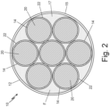
- FIG. 2 is a cross-sectional view of heat exchanger 10 taken along line A-A from FIG. 1 .
- outer housing 12 can include cylindrical tube portion 15, first end 16a, second end 16b, interior space 17, inlet 18, and outlet 19.
- Each phase change element 14 can include core 20 and membrane 22.
- Coolant fluid F is also shown flowing through heat exchanger 10.
- Outer housing 12 forms an outer shell of heat exchanger 10 that encloses interior space 17.
- Cylindrical tube portion 15 forms most of a length of outer housing 12, and first end 16a is connected to cylindrical tube portion 15 opposite second end 16b.
- First end 16a and second end 16b can both be hemispherical in shape such that first end 16a, second end 16b, and cylindrical tube portion 15 form outer housing 12 into a capsule-shaped pressure vessel capable of handling a pressurized flow of coolant fluid F.
- outer housing 12 can be spherically shaped, elliptically shaped, or any other shape ideal for containing a pressurized flow of coolant fluid F.
- Outer housing 12 can also be formed from a composite material, such as carbon fiber composite, to reduce an overall weight of heat exchanger 10 and to increase a pressure holding capacity of outer housing 12.
- Inlet 18 is formed in outer housing 12 and extends through outer housing 12 such that inlet 18 is in fluidic communication with interior space 17.
- Outlet 19 is also formed in outer housing 12 and extends through outer housing 12 such that outlet 19 is in fluidic communication with interior space 17.
- Phase change elements 14 are in interior space 17 within outer housing 12. Outer housing 12 surrounds phase change elements 14 to form flow channels between outer housing 12 and phase change elements 14. Phase change elements 14 can also be arranged relative to each other within interior space 17 to form flow channels between phase change elements 14.
- each phase change element 14 is cylindrical in shape and extends inside of outer housing 12 from first end 16a to second end 16b. The plurality of phase change elements 14 are arranged together such that phase change elements 14 are stacked in layers and are generally parallel with cylindrical tube portion 15 of outer housing 12.
- Each phase change element 14 includes core 20 and membrane 22.
- Core 20 includes a phase change material that changes phases from a solid to a liquid as core 20 absorbs heat from coolant fluid F during operation of heat exchanger 10.
- the phase change material can be selected from, but is not limited to, the group comprising paraffin wax, hydrated salts, fatty acids, ice/water, low melting point metals (such as gallium or other metals with a melting point below 93.33°C (200°F)), and shape memory alloys.
- Membrane 22 completely covers core 20 and is made of an elastic material that is impermeable and chemically non-reactive to the phase change material, and impermeable and chemically non-reactive to coolant fluid F.
- the elastic material of membrane 22 also allows membrane 22 to expand and contract as the phase change material of core 20 phase changes and cycles back and forth from a solid to a liquid.
- the elastic material of membrane 22 can include rubber.
- the elastic material of membrane 22 can be ethylene propylene diene monomer (EPDM).
- a flow of coolant fluid F enters heat exchanger 10 through inlet 18.
- the flow of coolant fluid F enters interior space 17 and flows through the flow channels between phase change elements 14 and the flow channels between outer housing 12 and phase change elements 14.
- phase change elements 14 absorb heat from coolant fluid F.
- core 20 of each phase change element 14 can begin to melt and change phase from a solid to a liquid.
- Membrane 22 of each phase change element 14 helps phase change element 14 retain structure and prevents the flow of coolant fluid F from eroding core 20. Membrane 22 also prevents core 20 from chemically interacting with coolant fluid F.
- coolant fluid F exits interior space 17 through outlet 19.
- phase change elements 14 Heat transfer between coolant fluid F and phase change elements 14 is faster than conventional heat exchangers because phase change elements 14 are in direct contact with coolant fluid F. Performance of heat exchanger 10 is not dependent on heat transferring across outer housing 12 to an outside medium. Rather, outer housing 12 serves as a pressure vessel that allows coolant fluid F to flow through heat exchanger 10 at a higher rate than conventional heat exchangers. While phase change elements 14 are shown as having a cylindrical shape in the example of FIGS. 1 and 2 , phase change elements 14 can have any shape that creates internal flow channels. Some alternative examples of phase change elements 14 are discussed below with reference to FIGS. 3 and 4 .
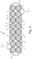
- FIG. 3 is a cross-sectional view of another example of heat exchanger 10 with phase change elements 14 that are spherically shaped.
- Each of the spherically shaped phase change elements 14 can include a diameter that is larger than a diameter of inlet 18 and a diameter of outlet 19, thereby preventing phase change elements 14 from being carried out of heat exchanger 10 by the flow of coolant fluid F.
- core 20 of each phase change element 14 can be spherical.
- the spherically shaped phase change elements 14 are stacked within interior space 17 so as to form flow channels between phase change elements 14, and to form flow channels between outer housing 12 and phase change elements 14.
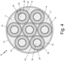
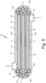
- FIG. 4 is a cross-sectional view of another example of heat exchanger 10 with phase change elements 14 that are tubular in shape with center passage 24 extending along a center of each phase change element 14.
- core 20 is tube shaped and membrane 22 completely covers core 20 such that membrane 22 lines center passage 24, covers a radial outer surface of core 20, and covers the ends of core 20.
- coolant fluid F flows between phase change elements 14, between phase change elements 14 and outer housing 12, and inside of center passage 24 of each phase change element 14.
- Center passage 24 increases the surface area of each phase change element 14 over the example of FIGS. 1 and 2 .
- FIG. 5 is a cross-sectional view of another example of heat exchanger 10 with cylindrically shaped phase change elements 14a and spherically shaped phase change elements 14b.
- the cylindrically shaped phase change elements 14a surround the spherically shaped phase change elements 14b such that the cylindrically shaped phase change elements 14a hold the spherically shaped phase change elements 14b in place.
- the spherically shaped phase change elements 14b are positioned along a center axis of outer housing 12 and interior space 17, and the cylindrically shaped phase change elements 14a extend circumferentially around the spherically shaped phase change elements 14b.
- the cylindrically shaped phase change elements 14b prevent the spherically shaped phase change elements 14a from moving toward outlet 19 or inlet 18 and exiting outer housing 12.
- FIG. 6 is a cross-sectional view of another example of heat exchanger 10 with cylindrically shaped phase change elements 14a and spherically shaped phase change elements 14b inside of outer housing 12.
- the cylindrically shaped phase change elements 14a extend axially within interior space 17 of cylindrical tube portion 15 of outer housing 12.
- the cylindrical shaped phase change elements 14a extend past outlet 19 toward first end 16a of outer housing 12 and extend past inlet 18 toward second end 16b of outer housing 12.
- the spherically shaped phase change elements 14b are located in the hemispherical shape of first end 16a and within the hemispherical shape of second end 16b of outer housing 12.
- the spherically shaped phase change elements 14b increase the total surface area of phase changes elements 14 over the example of FIGS. 1 and 2 while the cylindrically shaped phase change elements 14a hold the spherically shaped phase change elements 14b in place and prevent the spherically shaped phase change elements 14b from moving toward outlet 19 or inlet 18 and exiting outer housing 12.
- FIG. 7 is a cross-sectional view of another example of heat exchanger 10 with phase change elements 14 supported inside of outer housing 12 by racks 26.
- Phase change elements 14 in the example of FIG. 7 can be tube shaped and similar to the phase change elements 14 in the example of FIG. 4 with center passage 24 extending along a center of each phase change element 14.
- core 20 of each phase change element 14 is tube shaped with membrane 22 completely covering core 20.
- Racks 26 are rigid support frames inside of outer housing 12 and connected to outer housing 12. Phase change elements 14 are inserted into racks 26 such that racks 26 physically support phase change elements 14 and space phase change elements 14 apart from one another.
- Heat exchanger 10 can also include a first plurality of flow guide channels 28 and a second plurality of flow guide channels 30.
- the first plurality of flow guide channels 28 are formed in the hemispherical shape of second end 16b of outer housing 12.
- the second plurality of flow guide channels 30 are formed in the hemispherical shape of first end 16a of outer housing 12.
- coolant fluid F flows into heat exchanger 10 through inlet 18 and then coolant fluid F is guided into and around phase change elements 14 by the first plurality of flow guide channels 28. Coolant fluid F then flows across phase change elements 14 and racks 26. As coolant fluid F flows though, between, and around phase change elements 14, phase change elements 14 absorb heat from coolant fluid F. As phase change elements 14 absorb heat from coolant fluid F, core 20 of each phase change element 14 may begin to melt and change phase from a solid to a liquid. Membrane 22 of each phase change element 14 helps phase change element 14 retain structure and prevents the flow of coolant fluid F from eroding core 20.
- Membrane 22 also prevents core 20 from chemically interacting with coolant fluid F.
- Racks 26 can provide additional support to membrane 22 and core 20 as membrane 22 and core 20 warm up and possibly decrease in firmness. After coolant fluid F flows past phase change elements 14, the second plurality of flow guide channels 30 guides the flow of coolant fluid F toward outlet 19.
- FIG. 8 is a cross-sectional view of another example of heat exchanger 10 with phase change elements 14 with a core 20 made from a shape memory alloy.
- the shape memory alloy can include, but is not limited to, a copper-aluminum-nickel alloy, a nickel-titanium alloy, an iron-manganese-silicon alloy, a copper-zinc-aluminum alloy, a copper-aluminum-nickel alloy, a zinc-copper-gold-iron alloy, and/or combinations thereof.
- the shape memory alloy can reversibly transition between two phases: an austenite phase and a martensite phase. Because the shape memory alloy remains a solid between the two phases, core 20 of each phase change element 14 in the example of FIG. 8 does not require a membrane.
- coolant fluid F flows into heat exchanger 10 through inlet 18 and enters second end 16b of outer housing 12. Coolant fluid F then flows between and around phase change elements 14. As coolant fluid F flows between and around phase change elements 14, phase change elements 14 absorb heat from coolant fluid F. As phase change elements 14 absorb heat from coolant fluid F, core 20 of each phase change element 14 transitions from the martensite phase to the austenite phase. After coolant fluid F flows past phase change elements 14, the second plurality of flow guide channels 30 guides the flow of coolant fluid F toward outlet 19. When operation of heat exchanger 10 ends, phase change elements 14 cool and core 20 of each phase change element 14 transitions from the austenite phase to the martensite phase.
- a heat exchanger in one example, includes an outer shell enclosing an interior space.
- An inlet extends through the outer shell and is in fluidic communication with the interior space.
- An outlet extends through the outer shell and is in fluidic communication with the interior space.
- At least one phase change element is inside the interior space and includes a core comprising a phase change material.
- the heat exchanger of the preceding paragraph can optionally include, additionally and/or alternatively, any one or more of the following features, configurations and/or additional components:
- a heat exchanger in another example of the disclosure, includes a plurality of phase change elements.
- Each phase change element of the plurality of phase change elements includes a core with a phase change material.
- An outer housing surrounds the plurality of phase change elements and form flow channels between the outer housing and the plurality of phase change elements.
- An inlet is formed in the outer housing and is in fluidic communication with the flow channels.
- An outlet is formed in the outer housing and is in fluidic communication with the flow channels.
- the heat exchanger of the preceding paragraph can optionally include, additionally and/or alternatively, any one or more of the following features, configurations and/or additional components:
- FIGS. 1-4 show heat exchanger 10 as having a plurality of phase change elements 14 inside of outer housing 12, in other examples, heat exchanger 10 can include a single phase change element 14 having a core 20 with a relatively complex geometry covered by membrane 22.
- heat exchanger 10 can include a single phase change element 14 having a core 20 with a relatively complex geometry covered by membrane 22.
- many modifications may be made to adapt a particular situation or material to the teachings of the invention without departing from the essential scope thereof. Therefore, it is intended that the invention not be limited to the particular embodiment(s) disclosed, but that the invention will include all embodiments falling within the scope of the appended claims.
Landscapes
- Engineering & Computer Science (AREA)
- Physics & Mathematics (AREA)
- Thermal Sciences (AREA)
- Mechanical Engineering (AREA)
- General Engineering & Computer Science (AREA)
- Chemical & Material Sciences (AREA)
- Dispersion Chemistry (AREA)
- Heat-Exchange Devices With Radiators And Conduit Assemblies (AREA)
Applications Claiming Priority (1)
| Application Number | Priority Date | Filing Date | Title |
|---|---|---|---|
| US18/532,411 US20250189237A1 (en) | 2023-12-07 | 2023-12-07 | Phase change material heat exchanger |
Publications (1)
| Publication Number | Publication Date |
|---|---|
| EP4567367A1 true EP4567367A1 (de) | 2025-06-11 |
Family
ID=93651323
Family Applications (1)
| Application Number | Title | Priority Date | Filing Date |
|---|---|---|---|
| EP24215222.1A Pending EP4567367A1 (de) | 2023-12-07 | 2024-11-25 | Phasenwechselmaterial-wärmetauscher |
Country Status (2)
| Country | Link |
|---|---|
| US (1) | US20250189237A1 (de) |
| EP (1) | EP4567367A1 (de) |
Families Citing this family (1)
| Publication number | Priority date | Publication date | Assignee | Title |
|---|---|---|---|---|
| WO2022259785A1 (ja) * | 2021-06-07 | 2022-12-15 | 吉野石膏株式会社 | 潜熱蓄熱石膏板、仕切り構造体 |
Citations (6)
| Publication number | Priority date | Publication date | Assignee | Title |
|---|---|---|---|---|
| JPS5776078A (en) * | 1980-10-29 | 1982-05-12 | Agency Of Ind Science & Technol | Heat accumulator utilizing latent heat |
| JPS58108391A (ja) * | 1981-12-23 | 1983-06-28 | Pentel Kk | 蓄熱構造体 |
| JPS62172191A (ja) * | 1986-01-23 | 1987-07-29 | Agency Of Ind Science & Technol | 蓄熱器 |
| JPH01212893A (ja) * | 1988-02-19 | 1989-08-25 | Agency Of Ind Science & Technol | 蓄熱体 |
| US20070029064A1 (en) * | 2005-08-03 | 2007-02-08 | Honeywell International, Inc. | Compact heat battery |
| US9410748B2 (en) * | 2010-08-06 | 2016-08-09 | Enolcon Gmbh | High-temperature heat store for solar-thermal power plants |
Family Cites Families (11)
| Publication number | Priority date | Publication date | Assignee | Title |
|---|---|---|---|---|
| US5220954A (en) * | 1992-10-07 | 1993-06-22 | Shape, Inc. | Phase change heat exchanger |
| JP3579435B2 (ja) * | 1993-05-19 | 2004-10-20 | 千代田化工建設株式会社 | 蓄熱槽 |
| JPH07229690A (ja) * | 1993-12-21 | 1995-08-29 | Matsushita Electric Works Ltd | 熱交換器 |
| US20110259544A1 (en) * | 2010-04-21 | 2011-10-27 | Lehigh University | Encapsulated phase change apparatus for thermal energy storage |
| WO2014100096A1 (en) * | 2012-12-18 | 2014-06-26 | University Of South Florida | Encapsulation of thermal energy storage media |
| ES2480765B1 (es) * | 2012-12-27 | 2015-05-08 | Universitat Politècnica De Catalunya | Sistema de almacenamiento de energía térmica combinando material sólido de calor sensible y material de cambio de fase |
| GB2578987B (en) * | 2017-09-01 | 2023-02-08 | Rogers Corp | Fusible phase-change powders for thermal management, methods of manufacture thereof, and articles containing the powders |
| CN108534578B (zh) * | 2018-03-07 | 2019-11-26 | 西安交通大学 | 一种填充床储热装置及储热球的制备方法 |
| US20210127890A1 (en) * | 2018-06-23 | 2021-05-06 | Pierre Maurice Baston | Insulating and cooling liquid container |
| US11812861B2 (en) * | 2021-09-22 | 2023-11-14 | L&P Property Management Company | Comfort layer with liquid pods and method of making same |
| JP7511054B1 (ja) * | 2023-05-31 | 2024-07-04 | みずほリサーチ&テクノロジーズ株式会社 | 色判定システム、色判定方法及び色判定プログラム |
-
2023
- 2023-12-07 US US18/532,411 patent/US20250189237A1/en active Pending
-
2024
- 2024-11-25 EP EP24215222.1A patent/EP4567367A1/de active Pending
Patent Citations (6)
| Publication number | Priority date | Publication date | Assignee | Title |
|---|---|---|---|---|
| JPS5776078A (en) * | 1980-10-29 | 1982-05-12 | Agency Of Ind Science & Technol | Heat accumulator utilizing latent heat |
| JPS58108391A (ja) * | 1981-12-23 | 1983-06-28 | Pentel Kk | 蓄熱構造体 |
| JPS62172191A (ja) * | 1986-01-23 | 1987-07-29 | Agency Of Ind Science & Technol | 蓄熱器 |
| JPH01212893A (ja) * | 1988-02-19 | 1989-08-25 | Agency Of Ind Science & Technol | 蓄熱体 |
| US20070029064A1 (en) * | 2005-08-03 | 2007-02-08 | Honeywell International, Inc. | Compact heat battery |
| US9410748B2 (en) * | 2010-08-06 | 2016-08-09 | Enolcon Gmbh | High-temperature heat store for solar-thermal power plants |
Also Published As
| Publication number | Publication date |
|---|---|
| US20250189237A1 (en) | 2025-06-12 |
Similar Documents
| Publication | Publication Date | Title |
|---|---|---|
| US8778063B2 (en) | Coiled and microchannel heat exchangers for metal hydride storage systems | |
| EP3981692B1 (de) | Druckbeaufschlagungsvorrichtung für eine mit flüssigem sauerstoff und methan angetriebene rakete sowie mit flüssigem sauerstoff und methan angetriebene rakete | |
| EP0916835B1 (de) | Rakete mit geschlossenem Kühlkreislauf | |
| US20250189237A1 (en) | Phase change material heat exchanger | |
| US7152665B2 (en) | Pressure tank | |
| JP7479129B2 (ja) | 固体水素貯蔵システムの熱伝達フィン及びその固体水素貯蔵装置 | |
| US20130199751A1 (en) | Heat storage device for an engine | |
| JP2006118569A (ja) | 水素貯蔵タンク及び開閉用バルブの交換方法 | |
| JPH01188402A (ja) | 水素化物の形の水素の貯蔵用圧力容器 | |
| US20130199750A1 (en) | Heat storage system for an engine | |
| JP2006316996A (ja) | 圧縮天然ガス又は水素用の高圧貯蔵タンクの溶融/凝固媒体を用いるガス冷却方法 | |
| CN110326155A (zh) | 具有一体化蒸气室的电池单池 | |
| JP2004526157A (ja) | 原子力発電所を運転する方法および原子力発電所 | |
| JP2011063166A (ja) | 流体抵抗低減装置 | |
| JP4420445B2 (ja) | 水素吸蔵合金容器 | |
| CN118149275A (zh) | 一种储氢压力容器及储氢系统及应用 | |
| CN113539530A (zh) | 深海潜航用固态堆芯核反应堆应急热量导出系统及工作方法 | |
| TWI895264B (zh) | 蓄熱單元 | |
| CN220436206U (zh) | 一种可控温的外置换热型金属氢化物储氢瓶结构 | |
| EP3415853A1 (de) | Wärmetauscher | |
| JP4575107B2 (ja) | 圧力容器 | |
| CN117647134A (zh) | 一种瞬时高效的储热式相变换热器 | |
| JP5169157B2 (ja) | 給湯システム | |
| CN211055354U (zh) | 一种船舶动力系统 | |
| JP5061529B2 (ja) | 高圧水素貯蔵容器 |
Legal Events
| Date | Code | Title | Description |
|---|---|---|---|
| PUAI | Public reference made under article 153(3) epc to a published international application that has entered the european phase |
Free format text: ORIGINAL CODE: 0009012 |
|
| STAA | Information on the status of an ep patent application or granted ep patent |
Free format text: STATUS: THE APPLICATION HAS BEEN PUBLISHED |
|
| AK | Designated contracting states |
Kind code of ref document: A1 Designated state(s): AL AT BE BG CH CY CZ DE DK EE ES FI FR GB GR HR HU IE IS IT LI LT LU LV MC ME MK MT NL NO PL PT RO RS SE SI SK SM TR |
|
| STAA | Information on the status of an ep patent application or granted ep patent |
Free format text: STATUS: REQUEST FOR EXAMINATION WAS MADE |
|
| 17P | Request for examination filed |
Effective date: 20251208 |
|
| STAA | Information on the status of an ep patent application or granted ep patent |
Free format text: STATUS: EXAMINATION IS IN PROGRESS |
|
| 17Q | First examination report despatched |
Effective date: 20260325 |