EP4567360A2 - High-purity oxygen production method, and air separation device for producing high-purity oxygen - Google Patents
High-purity oxygen production method, and air separation device for producing high-purity oxygen Download PDFInfo
- Publication number
- EP4567360A2 EP4567360A2 EP24217636.0A EP24217636A EP4567360A2 EP 4567360 A2 EP4567360 A2 EP 4567360A2 EP 24217636 A EP24217636 A EP 24217636A EP 4567360 A2 EP4567360 A2 EP 4567360A2
- Authority
- EP
- European Patent Office
- Prior art keywords
- nitrogen
- oxygen
- rectification column
- gas
- condenser
- Prior art date
- Legal status (The legal status is an assumption and is not a legal conclusion. Google has not performed a legal analysis and makes no representation as to the accuracy of the status listed.)
- Pending
Links
Images


Classifications
-
- F—MECHANICAL ENGINEERING; LIGHTING; HEATING; WEAPONS; BLASTING
- F25—REFRIGERATION OR COOLING; COMBINED HEATING AND REFRIGERATION SYSTEMS; HEAT PUMP SYSTEMS; MANUFACTURE OR STORAGE OF ICE; LIQUEFACTION SOLIDIFICATION OF GASES
- F25J—LIQUEFACTION, SOLIDIFICATION OR SEPARATION OF GASES OR GASEOUS OR LIQUEFIED GASEOUS MIXTURES BY PRESSURE AND COLD TREATMENT OR BY BRINGING THEM INTO THE SUPERCRITICAL STATE
- F25J3/00—Processes or apparatus for separating the constituents of gaseous or liquefied gaseous mixtures involving the use of liquefaction or solidification
- F25J3/02—Processes or apparatus for separating the constituents of gaseous or liquefied gaseous mixtures involving the use of liquefaction or solidification by rectification, i.e. by continuous interchange of heat and material between a vapour stream and a liquid stream
- F25J3/04—Processes or apparatus for separating the constituents of gaseous or liquefied gaseous mixtures involving the use of liquefaction or solidification by rectification, i.e. by continuous interchange of heat and material between a vapour stream and a liquid stream for air
- F25J3/04248—Generation of cold for compensating heat leaks or liquid production, e.g. by Joule-Thompson expansion
- F25J3/04284—Generation of cold for compensating heat leaks or liquid production, e.g. by Joule-Thompson expansion using internal refrigeration by open-loop gas work expansion, e.g. of intermediate or oxygen enriched (waste-)streams
- F25J3/04309—Generation of cold for compensating heat leaks or liquid production, e.g. by Joule-Thompson expansion using internal refrigeration by open-loop gas work expansion, e.g. of intermediate or oxygen enriched (waste-)streams of nitrogen
-
- F—MECHANICAL ENGINEERING; LIGHTING; HEATING; WEAPONS; BLASTING
- F25—REFRIGERATION OR COOLING; COMBINED HEATING AND REFRIGERATION SYSTEMS; HEAT PUMP SYSTEMS; MANUFACTURE OR STORAGE OF ICE; LIQUEFACTION SOLIDIFICATION OF GASES
- F25J—LIQUEFACTION, SOLIDIFICATION OR SEPARATION OF GASES OR GASEOUS OR LIQUEFIED GASEOUS MIXTURES BY PRESSURE AND COLD TREATMENT OR BY BRINGING THEM INTO THE SUPERCRITICAL STATE
- F25J3/00—Processes or apparatus for separating the constituents of gaseous or liquefied gaseous mixtures involving the use of liquefaction or solidification
- F25J3/02—Processes or apparatus for separating the constituents of gaseous or liquefied gaseous mixtures involving the use of liquefaction or solidification by rectification, i.e. by continuous interchange of heat and material between a vapour stream and a liquid stream
- F25J3/04—Processes or apparatus for separating the constituents of gaseous or liquefied gaseous mixtures involving the use of liquefaction or solidification by rectification, i.e. by continuous interchange of heat and material between a vapour stream and a liquid stream for air
- F25J3/04006—Providing pressurised feed air or process streams within or from the air fractionation unit
- F25J3/04048—Providing pressurised feed air or process streams within or from the air fractionation unit by compression of cold gaseous streams, e.g. intermediate or oxygen enriched (waste) streams
- F25J3/04054—Providing pressurised feed air or process streams within or from the air fractionation unit by compression of cold gaseous streams, e.g. intermediate or oxygen enriched (waste) streams of air
-
- F—MECHANICAL ENGINEERING; LIGHTING; HEATING; WEAPONS; BLASTING
- F25—REFRIGERATION OR COOLING; COMBINED HEATING AND REFRIGERATION SYSTEMS; HEAT PUMP SYSTEMS; MANUFACTURE OR STORAGE OF ICE; LIQUEFACTION SOLIDIFICATION OF GASES
- F25J—LIQUEFACTION, SOLIDIFICATION OR SEPARATION OF GASES OR GASEOUS OR LIQUEFIED GASEOUS MIXTURES BY PRESSURE AND COLD TREATMENT OR BY BRINGING THEM INTO THE SUPERCRITICAL STATE
- F25J3/00—Processes or apparatus for separating the constituents of gaseous or liquefied gaseous mixtures involving the use of liquefaction or solidification
- F25J3/02—Processes or apparatus for separating the constituents of gaseous or liquefied gaseous mixtures involving the use of liquefaction or solidification by rectification, i.e. by continuous interchange of heat and material between a vapour stream and a liquid stream
- F25J3/04—Processes or apparatus for separating the constituents of gaseous or liquefied gaseous mixtures involving the use of liquefaction or solidification by rectification, i.e. by continuous interchange of heat and material between a vapour stream and a liquid stream for air
- F25J3/04006—Providing pressurised feed air or process streams within or from the air fractionation unit
- F25J3/04048—Providing pressurised feed air or process streams within or from the air fractionation unit by compression of cold gaseous streams, e.g. intermediate or oxygen enriched (waste) streams
-
- F—MECHANICAL ENGINEERING; LIGHTING; HEATING; WEAPONS; BLASTING
- F25—REFRIGERATION OR COOLING; COMBINED HEATING AND REFRIGERATION SYSTEMS; HEAT PUMP SYSTEMS; MANUFACTURE OR STORAGE OF ICE; LIQUEFACTION SOLIDIFICATION OF GASES
- F25J—LIQUEFACTION, SOLIDIFICATION OR SEPARATION OF GASES OR GASEOUS OR LIQUEFIED GASEOUS MIXTURES BY PRESSURE AND COLD TREATMENT OR BY BRINGING THEM INTO THE SUPERCRITICAL STATE
- F25J3/00—Processes or apparatus for separating the constituents of gaseous or liquefied gaseous mixtures involving the use of liquefaction or solidification
- F25J3/02—Processes or apparatus for separating the constituents of gaseous or liquefied gaseous mixtures involving the use of liquefaction or solidification by rectification, i.e. by continuous interchange of heat and material between a vapour stream and a liquid stream
- F25J3/04—Processes or apparatus for separating the constituents of gaseous or liquefied gaseous mixtures involving the use of liquefaction or solidification by rectification, i.e. by continuous interchange of heat and material between a vapour stream and a liquid stream for air
- F25J3/04006—Providing pressurised feed air or process streams within or from the air fractionation unit
- F25J3/04078—Providing pressurised feed air or process streams within or from the air fractionation unit providing pressurized products by liquid compression and vaporisation with cold recovery, i.e. so-called internal compression
- F25J3/0409—Providing pressurised feed air or process streams within or from the air fractionation unit providing pressurized products by liquid compression and vaporisation with cold recovery, i.e. so-called internal compression of oxygen
-
- F—MECHANICAL ENGINEERING; LIGHTING; HEATING; WEAPONS; BLASTING
- F25—REFRIGERATION OR COOLING; COMBINED HEATING AND REFRIGERATION SYSTEMS; HEAT PUMP SYSTEMS; MANUFACTURE OR STORAGE OF ICE; LIQUEFACTION SOLIDIFICATION OF GASES
- F25J—LIQUEFACTION, SOLIDIFICATION OR SEPARATION OF GASES OR GASEOUS OR LIQUEFIED GASEOUS MIXTURES BY PRESSURE AND COLD TREATMENT OR BY BRINGING THEM INTO THE SUPERCRITICAL STATE
- F25J3/00—Processes or apparatus for separating the constituents of gaseous or liquefied gaseous mixtures involving the use of liquefaction or solidification
- F25J3/02—Processes or apparatus for separating the constituents of gaseous or liquefied gaseous mixtures involving the use of liquefaction or solidification by rectification, i.e. by continuous interchange of heat and material between a vapour stream and a liquid stream
- F25J3/04—Processes or apparatus for separating the constituents of gaseous or liquefied gaseous mixtures involving the use of liquefaction or solidification by rectification, i.e. by continuous interchange of heat and material between a vapour stream and a liquid stream for air
- F25J3/04151—Purification and (pre-)cooling of the feed air; recuperative heat-exchange with product streams
- F25J3/04187—Cooling of the purified feed air by recuperative heat-exchange; Heat-exchange with product streams
-
- F—MECHANICAL ENGINEERING; LIGHTING; HEATING; WEAPONS; BLASTING
- F25—REFRIGERATION OR COOLING; COMBINED HEATING AND REFRIGERATION SYSTEMS; HEAT PUMP SYSTEMS; MANUFACTURE OR STORAGE OF ICE; LIQUEFACTION SOLIDIFICATION OF GASES
- F25J—LIQUEFACTION, SOLIDIFICATION OR SEPARATION OF GASES OR GASEOUS OR LIQUEFIED GASEOUS MIXTURES BY PRESSURE AND COLD TREATMENT OR BY BRINGING THEM INTO THE SUPERCRITICAL STATE
- F25J3/00—Processes or apparatus for separating the constituents of gaseous or liquefied gaseous mixtures involving the use of liquefaction or solidification
- F25J3/02—Processes or apparatus for separating the constituents of gaseous or liquefied gaseous mixtures involving the use of liquefaction or solidification by rectification, i.e. by continuous interchange of heat and material between a vapour stream and a liquid stream
- F25J3/04—Processes or apparatus for separating the constituents of gaseous or liquefied gaseous mixtures involving the use of liquefaction or solidification by rectification, i.e. by continuous interchange of heat and material between a vapour stream and a liquid stream for air
- F25J3/04151—Purification and (pre-)cooling of the feed air; recuperative heat-exchange with product streams
- F25J3/04187—Cooling of the purified feed air by recuperative heat-exchange; Heat-exchange with product streams
- F25J3/04236—Integration of different exchangers in a single core, so-called integrated cores
-
- F—MECHANICAL ENGINEERING; LIGHTING; HEATING; WEAPONS; BLASTING
- F25—REFRIGERATION OR COOLING; COMBINED HEATING AND REFRIGERATION SYSTEMS; HEAT PUMP SYSTEMS; MANUFACTURE OR STORAGE OF ICE; LIQUEFACTION SOLIDIFICATION OF GASES
- F25J—LIQUEFACTION, SOLIDIFICATION OR SEPARATION OF GASES OR GASEOUS OR LIQUEFIED GASEOUS MIXTURES BY PRESSURE AND COLD TREATMENT OR BY BRINGING THEM INTO THE SUPERCRITICAL STATE
- F25J3/00—Processes or apparatus for separating the constituents of gaseous or liquefied gaseous mixtures involving the use of liquefaction or solidification
- F25J3/02—Processes or apparatus for separating the constituents of gaseous or liquefied gaseous mixtures involving the use of liquefaction or solidification by rectification, i.e. by continuous interchange of heat and material between a vapour stream and a liquid stream
- F25J3/04—Processes or apparatus for separating the constituents of gaseous or liquefied gaseous mixtures involving the use of liquefaction or solidification by rectification, i.e. by continuous interchange of heat and material between a vapour stream and a liquid stream for air
- F25J3/04248—Generation of cold for compensating heat leaks or liquid production, e.g. by Joule-Thompson expansion
- F25J3/04254—Generation of cold for compensating heat leaks or liquid production, e.g. by Joule-Thompson expansion using the cold stored in external cryogenic fluids
- F25J3/0426—The cryogenic component does not participate in the fractionation
-
- F—MECHANICAL ENGINEERING; LIGHTING; HEATING; WEAPONS; BLASTING
- F25—REFRIGERATION OR COOLING; COMBINED HEATING AND REFRIGERATION SYSTEMS; HEAT PUMP SYSTEMS; MANUFACTURE OR STORAGE OF ICE; LIQUEFACTION SOLIDIFICATION OF GASES
- F25J—LIQUEFACTION, SOLIDIFICATION OR SEPARATION OF GASES OR GASEOUS OR LIQUEFIED GASEOUS MIXTURES BY PRESSURE AND COLD TREATMENT OR BY BRINGING THEM INTO THE SUPERCRITICAL STATE
- F25J3/00—Processes or apparatus for separating the constituents of gaseous or liquefied gaseous mixtures involving the use of liquefaction or solidification
- F25J3/02—Processes or apparatus for separating the constituents of gaseous or liquefied gaseous mixtures involving the use of liquefaction or solidification by rectification, i.e. by continuous interchange of heat and material between a vapour stream and a liquid stream
- F25J3/04—Processes or apparatus for separating the constituents of gaseous or liquefied gaseous mixtures involving the use of liquefaction or solidification by rectification, i.e. by continuous interchange of heat and material between a vapour stream and a liquid stream for air
- F25J3/04248—Generation of cold for compensating heat leaks or liquid production, e.g. by Joule-Thompson expansion
- F25J3/04284—Generation of cold for compensating heat leaks or liquid production, e.g. by Joule-Thompson expansion using internal refrigeration by open-loop gas work expansion, e.g. of intermediate or oxygen enriched (waste-)streams
-
- F—MECHANICAL ENGINEERING; LIGHTING; HEATING; WEAPONS; BLASTING
- F25—REFRIGERATION OR COOLING; COMBINED HEATING AND REFRIGERATION SYSTEMS; HEAT PUMP SYSTEMS; MANUFACTURE OR STORAGE OF ICE; LIQUEFACTION SOLIDIFICATION OF GASES
- F25J—LIQUEFACTION, SOLIDIFICATION OR SEPARATION OF GASES OR GASEOUS OR LIQUEFIED GASEOUS MIXTURES BY PRESSURE AND COLD TREATMENT OR BY BRINGING THEM INTO THE SUPERCRITICAL STATE
- F25J3/00—Processes or apparatus for separating the constituents of gaseous or liquefied gaseous mixtures involving the use of liquefaction or solidification
- F25J3/02—Processes or apparatus for separating the constituents of gaseous or liquefied gaseous mixtures involving the use of liquefaction or solidification by rectification, i.e. by continuous interchange of heat and material between a vapour stream and a liquid stream
- F25J3/04—Processes or apparatus for separating the constituents of gaseous or liquefied gaseous mixtures involving the use of liquefaction or solidification by rectification, i.e. by continuous interchange of heat and material between a vapour stream and a liquid stream for air
- F25J3/04248—Generation of cold for compensating heat leaks or liquid production, e.g. by Joule-Thompson expansion
- F25J3/04284—Generation of cold for compensating heat leaks or liquid production, e.g. by Joule-Thompson expansion using internal refrigeration by open-loop gas work expansion, e.g. of intermediate or oxygen enriched (waste-)streams
- F25J3/0429—Generation of cold for compensating heat leaks or liquid production, e.g. by Joule-Thompson expansion using internal refrigeration by open-loop gas work expansion, e.g. of intermediate or oxygen enriched (waste-)streams of feed air, e.g. used as waste or product air or expanded into an auxiliary column
- F25J3/04303—Lachmann expansion, i.e. expanded into oxygen producing or low pressure column
-
- F—MECHANICAL ENGINEERING; LIGHTING; HEATING; WEAPONS; BLASTING
- F25—REFRIGERATION OR COOLING; COMBINED HEATING AND REFRIGERATION SYSTEMS; HEAT PUMP SYSTEMS; MANUFACTURE OR STORAGE OF ICE; LIQUEFACTION SOLIDIFICATION OF GASES
- F25J—LIQUEFACTION, SOLIDIFICATION OR SEPARATION OF GASES OR GASEOUS OR LIQUEFIED GASEOUS MIXTURES BY PRESSURE AND COLD TREATMENT OR BY BRINGING THEM INTO THE SUPERCRITICAL STATE
- F25J3/00—Processes or apparatus for separating the constituents of gaseous or liquefied gaseous mixtures involving the use of liquefaction or solidification
- F25J3/02—Processes or apparatus for separating the constituents of gaseous or liquefied gaseous mixtures involving the use of liquefaction or solidification by rectification, i.e. by continuous interchange of heat and material between a vapour stream and a liquid stream
- F25J3/04—Processes or apparatus for separating the constituents of gaseous or liquefied gaseous mixtures involving the use of liquefaction or solidification by rectification, i.e. by continuous interchange of heat and material between a vapour stream and a liquid stream for air
- F25J3/04248—Generation of cold for compensating heat leaks or liquid production, e.g. by Joule-Thompson expansion
- F25J3/04284—Generation of cold for compensating heat leaks or liquid production, e.g. by Joule-Thompson expansion using internal refrigeration by open-loop gas work expansion, e.g. of intermediate or oxygen enriched (waste-)streams
- F25J3/04321—Generation of cold for compensating heat leaks or liquid production, e.g. by Joule-Thompson expansion using internal refrigeration by open-loop gas work expansion, e.g. of intermediate or oxygen enriched (waste-)streams of oxygen
-
- F—MECHANICAL ENGINEERING; LIGHTING; HEATING; WEAPONS; BLASTING
- F25—REFRIGERATION OR COOLING; COMBINED HEATING AND REFRIGERATION SYSTEMS; HEAT PUMP SYSTEMS; MANUFACTURE OR STORAGE OF ICE; LIQUEFACTION SOLIDIFICATION OF GASES
- F25J—LIQUEFACTION, SOLIDIFICATION OR SEPARATION OF GASES OR GASEOUS OR LIQUEFIED GASEOUS MIXTURES BY PRESSURE AND COLD TREATMENT OR BY BRINGING THEM INTO THE SUPERCRITICAL STATE
- F25J3/00—Processes or apparatus for separating the constituents of gaseous or liquefied gaseous mixtures involving the use of liquefaction or solidification
- F25J3/02—Processes or apparatus for separating the constituents of gaseous or liquefied gaseous mixtures involving the use of liquefaction or solidification by rectification, i.e. by continuous interchange of heat and material between a vapour stream and a liquid stream
- F25J3/04—Processes or apparatus for separating the constituents of gaseous or liquefied gaseous mixtures involving the use of liquefaction or solidification by rectification, i.e. by continuous interchange of heat and material between a vapour stream and a liquid stream for air
- F25J3/04248—Generation of cold for compensating heat leaks or liquid production, e.g. by Joule-Thompson expansion
- F25J3/04333—Generation of cold for compensating heat leaks or liquid production, e.g. by Joule-Thompson expansion using quasi-closed loop internal vapor compression refrigeration cycles, e.g. of intermediate or oxygen enriched (waste-)streams
-
- F—MECHANICAL ENGINEERING; LIGHTING; HEATING; WEAPONS; BLASTING
- F25—REFRIGERATION OR COOLING; COMBINED HEATING AND REFRIGERATION SYSTEMS; HEAT PUMP SYSTEMS; MANUFACTURE OR STORAGE OF ICE; LIQUEFACTION SOLIDIFICATION OF GASES
- F25J—LIQUEFACTION, SOLIDIFICATION OR SEPARATION OF GASES OR GASEOUS OR LIQUEFIED GASEOUS MIXTURES BY PRESSURE AND COLD TREATMENT OR BY BRINGING THEM INTO THE SUPERCRITICAL STATE
- F25J3/00—Processes or apparatus for separating the constituents of gaseous or liquefied gaseous mixtures involving the use of liquefaction or solidification
- F25J3/02—Processes or apparatus for separating the constituents of gaseous or liquefied gaseous mixtures involving the use of liquefaction or solidification by rectification, i.e. by continuous interchange of heat and material between a vapour stream and a liquid stream
- F25J3/04—Processes or apparatus for separating the constituents of gaseous or liquefied gaseous mixtures involving the use of liquefaction or solidification by rectification, i.e. by continuous interchange of heat and material between a vapour stream and a liquid stream for air
- F25J3/04248—Generation of cold for compensating heat leaks or liquid production, e.g. by Joule-Thompson expansion
- F25J3/04375—Details relating to the work expansion, e.g. process parameter etc.
-
- F—MECHANICAL ENGINEERING; LIGHTING; HEATING; WEAPONS; BLASTING
- F25—REFRIGERATION OR COOLING; COMBINED HEATING AND REFRIGERATION SYSTEMS; HEAT PUMP SYSTEMS; MANUFACTURE OR STORAGE OF ICE; LIQUEFACTION SOLIDIFICATION OF GASES
- F25J—LIQUEFACTION, SOLIDIFICATION OR SEPARATION OF GASES OR GASEOUS OR LIQUEFIED GASEOUS MIXTURES BY PRESSURE AND COLD TREATMENT OR BY BRINGING THEM INTO THE SUPERCRITICAL STATE
- F25J3/00—Processes or apparatus for separating the constituents of gaseous or liquefied gaseous mixtures involving the use of liquefaction or solidification
- F25J3/02—Processes or apparatus for separating the constituents of gaseous or liquefied gaseous mixtures involving the use of liquefaction or solidification by rectification, i.e. by continuous interchange of heat and material between a vapour stream and a liquid stream
- F25J3/04—Processes or apparatus for separating the constituents of gaseous or liquefied gaseous mixtures involving the use of liquefaction or solidification by rectification, i.e. by continuous interchange of heat and material between a vapour stream and a liquid stream for air
- F25J3/04406—Processes or apparatus for separating the constituents of gaseous or liquefied gaseous mixtures involving the use of liquefaction or solidification by rectification, i.e. by continuous interchange of heat and material between a vapour stream and a liquid stream for air using a dual pressure main column system
- F25J3/04412—Processes or apparatus for separating the constituents of gaseous or liquefied gaseous mixtures involving the use of liquefaction or solidification by rectification, i.e. by continuous interchange of heat and material between a vapour stream and a liquid stream for air using a dual pressure main column system in a classical double column flowsheet, i.e. with thermal coupling by a main reboiler-condenser in the bottom of low pressure respectively top of high pressure column
-
- F—MECHANICAL ENGINEERING; LIGHTING; HEATING; WEAPONS; BLASTING
- F25—REFRIGERATION OR COOLING; COMBINED HEATING AND REFRIGERATION SYSTEMS; HEAT PUMP SYSTEMS; MANUFACTURE OR STORAGE OF ICE; LIQUEFACTION SOLIDIFICATION OF GASES
- F25J—LIQUEFACTION, SOLIDIFICATION OR SEPARATION OF GASES OR GASEOUS OR LIQUEFIED GASEOUS MIXTURES BY PRESSURE AND COLD TREATMENT OR BY BRINGING THEM INTO THE SUPERCRITICAL STATE
- F25J3/00—Processes or apparatus for separating the constituents of gaseous or liquefied gaseous mixtures involving the use of liquefaction or solidification
- F25J3/02—Processes or apparatus for separating the constituents of gaseous or liquefied gaseous mixtures involving the use of liquefaction or solidification by rectification, i.e. by continuous interchange of heat and material between a vapour stream and a liquid stream
- F25J3/04—Processes or apparatus for separating the constituents of gaseous or liquefied gaseous mixtures involving the use of liquefaction or solidification by rectification, i.e. by continuous interchange of heat and material between a vapour stream and a liquid stream for air
- F25J3/04406—Processes or apparatus for separating the constituents of gaseous or liquefied gaseous mixtures involving the use of liquefaction or solidification by rectification, i.e. by continuous interchange of heat and material between a vapour stream and a liquid stream for air using a dual pressure main column system
- F25J3/0443—A main column system not otherwise provided, e.g. a modified double column flowsheet
-
- F—MECHANICAL ENGINEERING; LIGHTING; HEATING; WEAPONS; BLASTING
- F25—REFRIGERATION OR COOLING; COMBINED HEATING AND REFRIGERATION SYSTEMS; HEAT PUMP SYSTEMS; MANUFACTURE OR STORAGE OF ICE; LIQUEFACTION SOLIDIFICATION OF GASES
- F25J—LIQUEFACTION, SOLIDIFICATION OR SEPARATION OF GASES OR GASEOUS OR LIQUEFIED GASEOUS MIXTURES BY PRESSURE AND COLD TREATMENT OR BY BRINGING THEM INTO THE SUPERCRITICAL STATE
- F25J3/00—Processes or apparatus for separating the constituents of gaseous or liquefied gaseous mixtures involving the use of liquefaction or solidification
- F25J3/02—Processes or apparatus for separating the constituents of gaseous or liquefied gaseous mixtures involving the use of liquefaction or solidification by rectification, i.e. by continuous interchange of heat and material between a vapour stream and a liquid stream
- F25J3/04—Processes or apparatus for separating the constituents of gaseous or liquefied gaseous mixtures involving the use of liquefaction or solidification by rectification, i.e. by continuous interchange of heat and material between a vapour stream and a liquid stream for air
- F25J3/04436—Processes or apparatus for separating the constituents of gaseous or liquefied gaseous mixtures involving the use of liquefaction or solidification by rectification, i.e. by continuous interchange of heat and material between a vapour stream and a liquid stream for air using at least a triple pressure main column system
- F25J3/04454—Processes or apparatus for separating the constituents of gaseous or liquefied gaseous mixtures involving the use of liquefaction or solidification by rectification, i.e. by continuous interchange of heat and material between a vapour stream and a liquid stream for air using at least a triple pressure main column system a main column system not otherwise provided, e.g. serially coupling of columns or more than three pressure levels
-
- F—MECHANICAL ENGINEERING; LIGHTING; HEATING; WEAPONS; BLASTING
- F25—REFRIGERATION OR COOLING; COMBINED HEATING AND REFRIGERATION SYSTEMS; HEAT PUMP SYSTEMS; MANUFACTURE OR STORAGE OF ICE; LIQUEFACTION SOLIDIFICATION OF GASES
- F25J—LIQUEFACTION, SOLIDIFICATION OR SEPARATION OF GASES OR GASEOUS OR LIQUEFIED GASEOUS MIXTURES BY PRESSURE AND COLD TREATMENT OR BY BRINGING THEM INTO THE SUPERCRITICAL STATE
- F25J3/00—Processes or apparatus for separating the constituents of gaseous or liquefied gaseous mixtures involving the use of liquefaction or solidification
- F25J3/02—Processes or apparatus for separating the constituents of gaseous or liquefied gaseous mixtures involving the use of liquefaction or solidification by rectification, i.e. by continuous interchange of heat and material between a vapour stream and a liquid stream
- F25J3/04—Processes or apparatus for separating the constituents of gaseous or liquefied gaseous mixtures involving the use of liquefaction or solidification by rectification, i.e. by continuous interchange of heat and material between a vapour stream and a liquid stream for air
- F25J3/04636—Processes or apparatus for separating the constituents of gaseous or liquefied gaseous mixtures involving the use of liquefaction or solidification by rectification, i.e. by continuous interchange of heat and material between a vapour stream and a liquid stream for air using a hybrid air separation unit, e.g. combined process by cryogenic separation and non-cryogenic separation techniques
-
- F—MECHANICAL ENGINEERING; LIGHTING; HEATING; WEAPONS; BLASTING
- F25—REFRIGERATION OR COOLING; COMBINED HEATING AND REFRIGERATION SYSTEMS; HEAT PUMP SYSTEMS; MANUFACTURE OR STORAGE OF ICE; LIQUEFACTION SOLIDIFICATION OF GASES
- F25J—LIQUEFACTION, SOLIDIFICATION OR SEPARATION OF GASES OR GASEOUS OR LIQUEFIED GASEOUS MIXTURES BY PRESSURE AND COLD TREATMENT OR BY BRINGING THEM INTO THE SUPERCRITICAL STATE
- F25J2200/00—Processes or apparatus using separation by rectification
- F25J2200/34—Processes or apparatus using separation by rectification using a side column fed by a stream from the low pressure column
-
- F—MECHANICAL ENGINEERING; LIGHTING; HEATING; WEAPONS; BLASTING
- F25—REFRIGERATION OR COOLING; COMBINED HEATING AND REFRIGERATION SYSTEMS; HEAT PUMP SYSTEMS; MANUFACTURE OR STORAGE OF ICE; LIQUEFACTION SOLIDIFICATION OF GASES
- F25J—LIQUEFACTION, SOLIDIFICATION OR SEPARATION OF GASES OR GASEOUS OR LIQUEFIED GASEOUS MIXTURES BY PRESSURE AND COLD TREATMENT OR BY BRINGING THEM INTO THE SUPERCRITICAL STATE
- F25J2200/00—Processes or apparatus using separation by rectification
- F25J2200/50—Processes or apparatus using separation by rectification using multiple (re-)boiler-condensers at different heights of the column
-
- F—MECHANICAL ENGINEERING; LIGHTING; HEATING; WEAPONS; BLASTING
- F25—REFRIGERATION OR COOLING; COMBINED HEATING AND REFRIGERATION SYSTEMS; HEAT PUMP SYSTEMS; MANUFACTURE OR STORAGE OF ICE; LIQUEFACTION SOLIDIFICATION OF GASES
- F25J—LIQUEFACTION, SOLIDIFICATION OR SEPARATION OF GASES OR GASEOUS OR LIQUEFIED GASEOUS MIXTURES BY PRESSURE AND COLD TREATMENT OR BY BRINGING THEM INTO THE SUPERCRITICAL STATE
- F25J2200/00—Processes or apparatus using separation by rectification
- F25J2200/50—Processes or apparatus using separation by rectification using multiple (re-)boiler-condensers at different heights of the column
- F25J2200/54—Processes or apparatus using separation by rectification using multiple (re-)boiler-condensers at different heights of the column in the low pressure column of a double pressure main column system
-
- F—MECHANICAL ENGINEERING; LIGHTING; HEATING; WEAPONS; BLASTING
- F25—REFRIGERATION OR COOLING; COMBINED HEATING AND REFRIGERATION SYSTEMS; HEAT PUMP SYSTEMS; MANUFACTURE OR STORAGE OF ICE; LIQUEFACTION SOLIDIFICATION OF GASES
- F25J—LIQUEFACTION, SOLIDIFICATION OR SEPARATION OF GASES OR GASEOUS OR LIQUEFIED GASEOUS MIXTURES BY PRESSURE AND COLD TREATMENT OR BY BRINGING THEM INTO THE SUPERCRITICAL STATE
- F25J2210/00—Processes characterised by the type or other details of the feed stream
- F25J2210/42—Nitrogen
-
- F—MECHANICAL ENGINEERING; LIGHTING; HEATING; WEAPONS; BLASTING
- F25—REFRIGERATION OR COOLING; COMBINED HEATING AND REFRIGERATION SYSTEMS; HEAT PUMP SYSTEMS; MANUFACTURE OR STORAGE OF ICE; LIQUEFACTION SOLIDIFICATION OF GASES
- F25J—LIQUEFACTION, SOLIDIFICATION OR SEPARATION OF GASES OR GASEOUS OR LIQUEFIED GASEOUS MIXTURES BY PRESSURE AND COLD TREATMENT OR BY BRINGING THEM INTO THE SUPERCRITICAL STATE
- F25J2210/00—Processes characterised by the type or other details of the feed stream
- F25J2210/50—Oxygen
-
- F—MECHANICAL ENGINEERING; LIGHTING; HEATING; WEAPONS; BLASTING
- F25—REFRIGERATION OR COOLING; COMBINED HEATING AND REFRIGERATION SYSTEMS; HEAT PUMP SYSTEMS; MANUFACTURE OR STORAGE OF ICE; LIQUEFACTION SOLIDIFICATION OF GASES
- F25J—LIQUEFACTION, SOLIDIFICATION OR SEPARATION OF GASES OR GASEOUS OR LIQUEFIED GASEOUS MIXTURES BY PRESSURE AND COLD TREATMENT OR BY BRINGING THEM INTO THE SUPERCRITICAL STATE
- F25J2215/00—Processes characterised by the type or other details of the product stream
- F25J2215/50—Oxygen or special cases, e.g. isotope-mixtures or low purity O2
- F25J2215/56—Ultra high purity oxygen, i.e. generally more than 99,9% O2
-
- F—MECHANICAL ENGINEERING; LIGHTING; HEATING; WEAPONS; BLASTING
- F25—REFRIGERATION OR COOLING; COMBINED HEATING AND REFRIGERATION SYSTEMS; HEAT PUMP SYSTEMS; MANUFACTURE OR STORAGE OF ICE; LIQUEFACTION SOLIDIFICATION OF GASES
- F25J—LIQUEFACTION, SOLIDIFICATION OR SEPARATION OF GASES OR GASEOUS OR LIQUEFIED GASEOUS MIXTURES BY PRESSURE AND COLD TREATMENT OR BY BRINGING THEM INTO THE SUPERCRITICAL STATE
- F25J2220/00—Processes or apparatus involving steps for the removal of impurities
- F25J2220/50—Separating low boiling, i.e. more volatile components from oxygen, e.g. N2, Ar
-
- F—MECHANICAL ENGINEERING; LIGHTING; HEATING; WEAPONS; BLASTING
- F25—REFRIGERATION OR COOLING; COMBINED HEATING AND REFRIGERATION SYSTEMS; HEAT PUMP SYSTEMS; MANUFACTURE OR STORAGE OF ICE; LIQUEFACTION SOLIDIFICATION OF GASES
- F25J—LIQUEFACTION, SOLIDIFICATION OR SEPARATION OF GASES OR GASEOUS OR LIQUEFIED GASEOUS MIXTURES BY PRESSURE AND COLD TREATMENT OR BY BRINGING THEM INTO THE SUPERCRITICAL STATE
- F25J2235/00—Processes or apparatus involving steps for increasing the pressure or for conveying of liquid process streams
- F25J2235/42—Processes or apparatus involving steps for increasing the pressure or for conveying of liquid process streams the fluid being nitrogen
-
- F—MECHANICAL ENGINEERING; LIGHTING; HEATING; WEAPONS; BLASTING
- F25—REFRIGERATION OR COOLING; COMBINED HEATING AND REFRIGERATION SYSTEMS; HEAT PUMP SYSTEMS; MANUFACTURE OR STORAGE OF ICE; LIQUEFACTION SOLIDIFICATION OF GASES
- F25J—LIQUEFACTION, SOLIDIFICATION OR SEPARATION OF GASES OR GASEOUS OR LIQUEFIED GASEOUS MIXTURES BY PRESSURE AND COLD TREATMENT OR BY BRINGING THEM INTO THE SUPERCRITICAL STATE
- F25J2245/00—Processes or apparatus involving steps for recycling of process streams
- F25J2245/02—Recycle of a stream in general, e.g. a by-pass stream
-
- F—MECHANICAL ENGINEERING; LIGHTING; HEATING; WEAPONS; BLASTING
- F25—REFRIGERATION OR COOLING; COMBINED HEATING AND REFRIGERATION SYSTEMS; HEAT PUMP SYSTEMS; MANUFACTURE OR STORAGE OF ICE; LIQUEFACTION SOLIDIFICATION OF GASES
- F25J—LIQUEFACTION, SOLIDIFICATION OR SEPARATION OF GASES OR GASEOUS OR LIQUEFIED GASEOUS MIXTURES BY PRESSURE AND COLD TREATMENT OR BY BRINGING THEM INTO THE SUPERCRITICAL STATE
- F25J2245/00—Processes or apparatus involving steps for recycling of process streams
- F25J2245/42—Processes or apparatus involving steps for recycling of process streams the recycled stream being nitrogen
-
- F—MECHANICAL ENGINEERING; LIGHTING; HEATING; WEAPONS; BLASTING
- F25—REFRIGERATION OR COOLING; COMBINED HEATING AND REFRIGERATION SYSTEMS; HEAT PUMP SYSTEMS; MANUFACTURE OR STORAGE OF ICE; LIQUEFACTION SOLIDIFICATION OF GASES
- F25J—LIQUEFACTION, SOLIDIFICATION OR SEPARATION OF GASES OR GASEOUS OR LIQUEFIED GASEOUS MIXTURES BY PRESSURE AND COLD TREATMENT OR BY BRINGING THEM INTO THE SUPERCRITICAL STATE
- F25J2250/00—Details related to the use of reboiler-condensers
- F25J2250/10—Boiler-condenser with superposed stages
-
- F—MECHANICAL ENGINEERING; LIGHTING; HEATING; WEAPONS; BLASTING
- F25—REFRIGERATION OR COOLING; COMBINED HEATING AND REFRIGERATION SYSTEMS; HEAT PUMP SYSTEMS; MANUFACTURE OR STORAGE OF ICE; LIQUEFACTION SOLIDIFICATION OF GASES
- F25J—LIQUEFACTION, SOLIDIFICATION OR SEPARATION OF GASES OR GASEOUS OR LIQUEFIED GASEOUS MIXTURES BY PRESSURE AND COLD TREATMENT OR BY BRINGING THEM INTO THE SUPERCRITICAL STATE
- F25J2250/00—Details related to the use of reboiler-condensers
- F25J2250/20—Boiler-condenser with multiple exchanger cores in parallel or with multiple re-boiling or condensing streams
Definitions
- the present invention relates to a high-purity oxygen production method and an air separation apparatus for producing high-purity oxygen.
- cryogenic air separation As high-purity oxygen production methods in which components having a higher boiling point or a lower boiling point than oxygen are controlled to the order of ppm or less, there are known methods that employ cryogenic air separation.
- One such production method that can be cited is a method in which an oxygen-containing liquid or gas is discharged from a cryogenic air separation apparatus, and high-purity oxygen is rectified (see, for example, WO2018/219685 A1 ).
- a process liquid such as an oxygen-enriched liquid is used as the heat medium, as in WO2018/219685 , since the sensible heat of the process liquid is used to provide the latent heat of vaporisation of the liquefied oxygen, a large molar flow rate is required, while at the same time the amount of heat supplied is limited by process balance constraints, and as a result there is a problem in that the amount of high-purity oxygen that can be recovered remains small.
- the present disclosure provides a high-purity oxygen production method and an air separation apparatus for producing high-purity oxygen, with which energy consumption is reduced even while a process gas is used as a heat medium for liquefied oxygen, so as to avoid high-purity oxygen production capacity constraints.
- US 2023/0038170 relates to a process for oxygen production at 99.8% content whereas the present invention allows oxygen to be produced with ppm order impurities.
- the liquid fed to the oxygen column comes from the liquid sump at the bottom of the column fed by the feed air, where hydrocarbons from feed air are accumulated.
- the feed (oxygen containing stream) to the pure oxygen column is comes from a section where hydrocarbons (eg. methane) have been removed.
- the difference between the boiling point of oxygen and the ⁇ T of the heat exchanger determine the saturation temperature and pressure of the condensable gas. Principally, the lower the saturation pressure, the less energy is needed for reboil.
- the present invention uses oxygen-enriched gas for oxygen reboil, where the saturation pressure can be lower than pure nitrogen.
- the method comprises:
- the oxygen-containing fluid may be a liquid or a gas-liquid mixture.
- the nitrogen gas in the vapour stream is caused to exchange heat with the oxygen-enriched liquid in the nitrogen condenser, thereby vaporising the oxygen-enriched liquid to generate oxygen-enriched gas.
- the oxygen-enriched gas which is utilised as a heat medium for the oxygen evaporator, has a pressure and composition sufficient to vaporise the rectified liquefied oxygen in the bottom portion of the high-purity oxygen rectification column using latent heat.
- oxygen-enriched gas containing a large amount of oxygen can vaporise liquefied oxygen at a lower pressure than air or nitrogen, liquefied oxygen can be vaporised at the supply pressure from the nitrogen evaporator without the use of a com pressor.
- the oxygen-containing gas condensed (re-liquefied) in the oxygen evaporator may be re-supplied to the nitrogen condenser.
- recondensed oxygen enriched liquid obtained by condensing the oxygen enriched gas in the oxygen evaporator is re-supplied to a refrigerant side of the nitrogen condenser and vaporised through heat exchange with the vapour stream (nitrogen gas).
- the recondensed oxygen enriched liquid may be delivered to the nitrogen condenser by means of a head pressure utilizing a height difference between the oxygen evaporator and the nitrogen condenser.
- delivery may be effected using a pump.
- the nitrogen rectification column may include a rectification portion for separating high boiling-point components (for example, methane) from the oxygen contained in the supplied feed air, and for discharging an oxygen-containing liquid from an upper stage thereof.
- high boiling-point components for example, methane
- the oxygen-containing liquid serving as the feedstock for the high-purity oxygen is obtained by discharging some reflux liquid from above the feed air introduction portion of the nitrogen rectification column as the oxygen-containing liquid, the reflux liquid containing sufficient oxygen to serve as a feedstock for the high-purity oxygen while having high boiling-point components removed sufficiently.
- a rectification portion is disposed midway between the feed air introduction portion and the oxygen-containing liquid discharge portion, and is configured such that high boiling-point components removed from the feed air are transferred into the liquefied oxygen by gas-liquid contact and are concentrated in the lower portion of the rectification column.
- the rectification portion may consist of rectification plates, structured packing, or random packing.
- a high-purity oxygen production method includes:
- a fourth high-purity oxygen production method includes:
- the first, second, third and fourth high-purity oxygen production methods may include a waste gas extraction step in which gas discharged from the top portion of the high-purity oxygen rectification column is passed through the main heat exchanger and is extracted as waste gas.
- High-purity oxygen is oxygen having a concentration of at least 99.99% mol. According to the present invention, there is provided an air separation apparatus for producing high purity oxygen, comprising:
- the air separation apparatus may comprise:
- a fourth air separation apparatus may comprise:
- the air separation apparatus may comprise:
- the air separation apparatus may include:
- Energy consumption can be reduced even while using a process gas as a heat medium for liquefied oxygen, so as to avoid high-purity oxygen production capacity constraints.
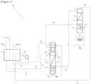
- the first air separation apparatus A1 according to a comparative example will be described with reference to Figure 1 .
- the first air separation apparatus A1 comprises a main heat exchanger 1, a nitrogen rectification column 2, a nitrogen condenser 3, an expansion turbine 92, a high-purity oxygen rectification column 5, and an oxygen evaporator 6.
- the main heat exchanger 1 cools feed air introduced from a hot end and discharges the same from a cold end.
- the cooled feed air is introduced into the nitrogen rectification column 2 via a feed air pipeline L1.
- the nitrogen rectification column 2 comprises a bottom portion 21, a rectification portion 22, and a top portion 23.
- the feed air pipeline L1 is connected to the bottom portion 21.
- Oxygen-enriched liquid that collects in the bottom portion 21 is sent to a refrigerant phase 31 of the nitrogen condenser 3 via an oxygen-enriched liquid pipeline L21.
- the nitrogen condenser 3 is provided above the top portion 23.
- a portion of nitrogen gas (vapour stream) discharged from the top 23 of the nitrogen rectification column 2 is introduced into the nitrogen condenser 3 via a reflux pipeline L231, and is cooled (condensed) through heat exchange with the oxygen-enriched liquid to form liquefied nitrogen.
- the liquefied nitrogen is returned to the top portion 23 of the nitrogen rectification column 2 as reflux liquid.
- An oxygen-containing fluid is discharged from between intermediate portions 221, 222 of the rectification portion 22 of the nitrogen rectification column 2 via the oxygen-containing fluid pipeline L221 and is introduced into a top portion 53 of the high-purity oxygen rectification column 5.
- Nitrogen gas discharged from the top portion 23 of the nitrogen rectification column 2 is sent via a product nitrogen gas extraction pipeline L23 to the main heat exchanger 1 and is extracted as product nitrogen gas.
- Oxygen-enriched gas (oxygen-enriched liquid vapour) discharged from a top portion 31 of the nitrogen condenser 3 is introduced via a waste gas extraction pipeline L31 into the cold end of the main heat exchanger 1, is discharged from an intermediate part thereof, is then expanded and cooled in the expansion turbine 92, and is again sent to the main heat exchanger 1 and is extracted as waste gas.
- a portion of the oxygen-enriched gas (oxygen-enriched liquid vapour) discharged from the top portion (refrigerant phase) 31 of the nitrogen condenser 3 is sent as a heat medium via a heat medium pipeline L311 to the oxygen evaporator 6, is re-liquefied, and is returned again to the top portion (refrigerant phase) 31 of the nitrogen condenser 3.
- the re-liquefied oxygen-enriched gas is supplied as a recycled oxygen-enriched liquid to the nitrogen condenser 3, as a refrigerant.
- the high-purity oxygen rectification column 5 includes a bottom portion 51, a rectification portion 52, and a top portion 53.
- Oxygen-containing liquid is introduced into the top portion 53 of the high-purity oxygen rectification column 5 and is rectified in the rectification portion 52, and liquefied oxygen collects in the bottom portion 51.
- the oxygen evaporator 6 is provided in the bottom portion 51 of the high-purity oxygen rectification column 5. Liquid oxygen is converted into a vapour stream (oxygen gas) by the heat medium nitrogen gas in the oxygen evaporator 6, heat and material are exchanged in the rectification portion 52, and high-purity oxygen accumulates in the bottom portion 51. Gas discharged from the top portion 53 of the high-purity oxygen rectification column 5 passes through a pipeline L53 to merge with the waste gas extraction pipeline L31, is sent to the main heat exchanger 1, and is extracted as waste gas.
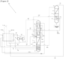
- the second air separation apparatus A2 according to the comparative example will be described with reference to Figure 2 .
- the same reference numerals as those in Figure 1 have the same functions, and therefore descriptions thereof may be omitted.
- the second air separation apparatus A2 comprises the main heat exchanger 1, the nitrogen rectification column 2, a first nitrogen condenser 3, a second nitrogen condenser 4, a compressor 91, the expansion turbine 92, the high-purity oxygen rectification column 5, and the oxygen evaporator 6. Aspects of the configuration that differ from embodiment 1 will mainly be described.
- the first nitrogen condenser 3 is disposed above the nitrogen rectification column 2, and the second nitrogen condenser 4 is disposed above the first nitrogen condenser 3.
- Some nitrogen gas (vapour stream) discharged from the top portion 23 of the nitrogen rectification column 2 is introduced into the first nitrogen condenser 3 via a first reflux pipeline L231, and is cooled (condensed) through heat exchange with the oxygen-enriched liquid to form liquefied nitrogen.
- the liquefied nitrogen is returned to the top portion 23 of the nitrogen rectification column 2 as reflux liquid.
- Some nitrogen gas (vapour stream) discharged from the top portion 23 of the nitrogen rectification column 2 is introduced into the second nitrogen condenser 4 via a second reflux pipeline L232, and is cooled (condensed) through heat exchange with the oxygen-enriched liquid to form liquefied nitrogen.
- the liquefied nitrogen is returned to the top portion 23 of the nitrogen rectification column 2 as reflux liquid.
- An oxygen-enriched liquid pipeline L211 is a pipeline through which oxygen-enriched liquid discharged from the bottom portion 21 of the nitrogen rectification column 2 is passed partially through the main heat exchanger 1 and is then introduced into the second nitrogen condenser 4.
- the oxygen-enriched liquid from the second nitrogen condenser 4 is sent as a refrigerant to the first nitrogen condenser 3.
- the compressor 91 compresses gas discharged from a top portion 41 of the second nitrogen condenser 4.
- a recycled gas pipeline L41 is a pipeline through which gas is discharged from the top portion 41 of the second nitrogen condenser 4, is compressed by the compressor 91, is passed through the main heat exchanger 1, and is then introduced as recycled gas into the rectification portion 22 of the nitrogen rectification column 2.
- the third air separation apparatus A3 comprises the main heat exchanger 1, a first nitrogen rectification column 2, a second nitrogen rectification column 7, the first nitrogen condenser 3, the second nitrogen condenser 4, the compressor 91, the expansion turbine 92, the high-purity oxygen rectification column 5, and the oxygen evaporator 6. Aspects of the configuration that differ from Figure 2 will mainly be described.
- Oxygen-enriched gas (vapour) generated in the first nitrogen condenser 3 and oxygen-enriched liquid discharged from the bottom portion 21 of the first nitrogen rectification column 2 are introduced into the second nitrogen rectification column 7.
- An oxygen-enriched liquid pipeline L212 is a pipeline through which oxygen-enriched liquid discharged from the bottom portion 21 of the first nitrogen rectification column 2 is introduced into the main heat exchanger 1, is discharged from an intermediate stage thereof, and is then introduced between intermediate stages 721 and 722 of the rectification portion of the second nitrogen rectification column 7.
- An oxygen-containing liquid pipeline L723 is a pipeline that introduces oxygen-containing fluid discharged from between intermediate stages 722, 723 of the rectification portion of the second nitrogen rectification column 7 into the top portion 53 of the high-purity oxygen rectification column 5.
- the position at which the oxygen-containing fluid is discharged into the oxygen-containing fluid pipeline L723 is above the position at which the oxygen-enriched liquid from the oxygen-enriched liquid pipeline L212 is introduced.
- a heat medium pipeline L711 is a pipeline through which gas (oxygen-enriched gas) discharged from below the lower-stage rectification portion 721 of the second nitrogen rectification column 7 is sent as a heat medium to the oxygen evaporator 6, is re-liquefied, and is sent as a refrigerant phase 41 to the second nitrogen condenser 4 via pipeline L61.
- a recycled gas pipeline L722 is a pipeline through which gas is discharged from between the intermediate stages 721 and 722 of the rectification portion of the second nitrogen rectification column 7, is compressed by the compressor 91, is passed through a portion of the main heat exchanger 1, and is then introduced as recycled gas into the rectification portion 22 of the first nitrogen rectification column 2.
- a waste gas extraction pipeline L411 is a pipeline through which gas discharged from the top portion 41 of the second nitrogen condenser 4 is passed partially through the main heat exchanger 1, is then sent to the expansion turbine 92 to be expanded and cooled, is again passed through the main heat exchanger 1, and is extracted as waste gas, after mixing with top gas from the oxygen rectification column.
- a vapour stream pipeline L731 is a pipeline through which a vapour stream that is discharged from a top portion 73 of the second nitrogen rectification column 7 and is sent to the second nitrogen condenser 4 and is returned in liquid form in part to the top portion 73 of the second nitrogen rectification column 7.
- a pipeline L732 branches off from the liquid stream pipeline L731 downstream of the second nitrogen condenser 4 and feeds into the top portion 23 of the first nitrogen rectification column 2.
- a liquid transfer pump P1 is provided in the pipeline L732.
- the fourth air separation apparatus A4 will be described with reference to Figure 4 .
- the same reference numerals as those in figures 2 and 3 have the same functions, and therefore descriptions thereof may be omitted.
- the fourth air separation apparatus A4 comprises the main heat exchanger 1, the first nitrogen rectification column 2, the second nitrogen rectification column 7, the first nitrogen condenser 3, the second nitrogen condenser 4, the compressor 911, the expansion turbine 921, the high-purity oxygen rectification column 5, and the oxygen evaporator 6. Aspects of the configuration that differ from figure 3 will mainly be described.
- the compressor 911 compresses a portion of the feed air.
- the expansion turbine 921 expands compressed air that has been compressed by the compressor 911, introduced into the main heat exchanger 1, and discharged from an intermediate part thereof.
- a feed air branch pipeline L11 is a pipeline that branches off from the feed air pipeline L1 upstream of the main heat exchanger 1, sends a portion of the feed air to the compressor 911 that compresses the feed air, sends the feed air compressed by the compressor 911 to the main heat exchanger 1 and discharges the same from an intermediate part thereof to the expansion turbine 921 that expands the feed air, and then sends the feed air to the rectification portion of the second nitrogen rectification column 7.
- a low-pressure nitrogen gas extraction pipeline L732 is a pipeline through which gas discharged from the top portion 73 of the second nitrogen rectification column 7 is extracted as low-pressure nitrogen gas.
- a waste gas extraction pipeline L412 is a pipeline through which gas discharged from the top portion 41 of the second nitrogen condenser 4 is extracted as waste gas.
- the pipeline L53 merges with the waste gas extraction pipeline L412.
- coldness required for the heat balance is obtained by using the expansion turbine 921 to expand either a portion of the feed air or product nitrogen gas discharged from the first nitrogen rectification column 2 to the pressure of the second nitrogen rectification column 7.
- Motive power obtained by the expansion turbine 921 may be applied to the motive power of the compressor 911 that compresses the feed air. It should be noted that the same applies to figures 2 and 3 .
- Nitrogen gas (330 Nm 3 /h, 9.7 barA), liquefied nitrogen (48 Nm3/h, 9.7 barA), oxygen-enriched liquid (552 Nm 3 /h, oxygen 35.3%) were discharged from the first nitrogen rectification column 2.
- the liquefied nitrogen and oxygen-enriched liquid were introduced into the second nitrogen rectification column 7.
- Low-pressure nitrogen gas (311 Nm3/h, 4.3 barA), oxygen-containing liquid (73 Nm3/h, 20.0 % O2), oxygen enriched gas (54Nm3/h, 4.3 barA, 36.3% O2), low-pressure oxygen enriched liquid (232 Nm3/h, 75.5% O2) were discharged from the second nitrogen rectification column 7.
- the oxygen enriched gas was used as the heat medium in the oxygen evaporator 6, and was introduced to the second nitrogen condenser 4 as a coolant.
- the low-pressure oxygen enriched liquid was introduced to the second nitrogen condenser 4 as a coolant.
- the oxygen-containing liquid was introduced to the oxygen rectification column.
- the oxygen rectification column 5 was operated at 1.5 barA, and high-purity oxygen (10.8 Nm 3 /h, 100%) collected in the bottom portion 51.
- the heat medium used in the oxygen evaporator 6 in the present example has a higher oxygen concentration than the feed air, thus allowing condensation to occur at a lower pressure such as 4.3 barA for the oxygen enriched gas instead of 9.9 barA for the feed air, and as a result reducing the compression energy required for the heat medium.
- the amount of feed air that can be supplied to the first nitrogen rectification column 2 can be increased, also making it possible to improve the nitrogen gas recovery.
- methane is distributed to the oxygen stream in the comparative example process because there is no mechanism to separate methane from oxygen, and the methane concentration in oxygen will be more than 4.8 ppm when 11 Nm3/h of oxygen is produced from 1000 Nm3/h of feed air.
- the oxygen-containing liquid supplied to the oxygen rectification column is derived from the methane-free reflux fluid above the location where the methane-containing fluid is supplied, so that an oxygen product with a methane content of less than 1 ppm can be produced.
Landscapes
- Engineering & Computer Science (AREA)
- Physics & Mathematics (AREA)
- Mechanical Engineering (AREA)
- Thermal Sciences (AREA)
- General Engineering & Computer Science (AREA)
- Health & Medical Sciences (AREA)
- Emergency Medicine (AREA)
- Separation By Low-Temperature Treatments (AREA)
- Oxygen, Ozone, And Oxides In General (AREA)
Abstract
Description
- The present invention relates to a high-purity oxygen production method and an air separation apparatus for producing high-purity oxygen.
- As high-purity oxygen production methods in which components having a higher boiling point or a lower boiling point than oxygen are controlled to the order of ppm or less, there are known methods that employ cryogenic air separation. One such production method that can be cited is a method in which an oxygen-containing liquid or gas is discharged from a cryogenic air separation apparatus, and high-purity oxygen is rectified (see, for example,
WO2018/219685 A1 ). - In order to rectify high-purity oxygen, a step is required in which feedstock liquefied oxygen is heated to vaporise low boiling point components such as nitrogen and argon, and as a heat medium for this process, it is known to use an oxygen-enriched liquid (
WO2018/219685 A1 ), feed air (WO2014/173496 A2 ), recycled air (JP 2020-173041 US11549747 - If a process liquid such as an oxygen-enriched liquid is used as the heat medium, as in
WO2018/219685 , since the sensible heat of the process liquid is used to provide the latent heat of vaporisation of the liquefied oxygen, a large molar flow rate is required, while at the same time the amount of heat supplied is limited by process balance constraints, and as a result there is a problem in that the amount of high-purity oxygen that can be recovered remains small. - In the methods of
WO2014/173496 A2 ,JP 2020-173041 US11549747 - The present disclosure provides a high-purity oxygen production method and an air separation apparatus for producing high-purity oxygen, with which energy consumption is reduced even while a process gas is used as a heat medium for liquefied oxygen, so as to avoid high-purity oxygen production capacity constraints.
US 2023/0038170 relates to a process for oxygen production at 99.8% content whereas the present invention allows oxygen to be produced with ppm order impurities. The liquid fed to the oxygen column comes from the liquid sump at the bottom of the column fed by the feed air, where hydrocarbons from feed air are accumulated. - According to the invention the feed (oxygen containing stream) to the pure oxygen column is comes from a section where hydrocarbons (eg. methane) have been removed.
- When condensable gas is introduced as a heat source for oxygen reboil, the difference between the boiling point of oxygen and the ΔT of the heat exchanger determine the saturation temperature and pressure of the condensable gas. Principally, the lower the saturation pressure, the less energy is needed for reboil. The present invention uses oxygen-enriched gas for oxygen reboil, where the saturation pressure can be lower than pure nitrogen.
- According to the invention, there is provided a method for producing high purity oxygen, comprising the following steps:
- a nitrogen and oxygen separation step of introducing a feed air cooled by a main heat exchanger to a lower section of a first nitrogen rectification column, and introducing oxygen-enriched liquid removed from the bottom of the first nitrogen rectification column into a rectification section of a second nitrogen rectification column and separating the feed air into a nitrogen-enriched component and an oxygen-enriched component in the first nitrogen rectification column and the second nitrogen rectification column;
- a first nitrogen condensation step of condensing vapor stream from the first nitrogen rectification column in a first nitrogen condenser;
- a second nitrogen condensation step of condensing vapor stream from the second nitrogen rectification column in a second nitrogen condenser;
- a high-purity oxygen production step of introducing an oxygen-containing fluid removed from the rectification section of the second nitrogen rectification column into a high-purity oxygen rectification column and producing high-purity product oxygen by using an oxygen evaporator; and
- a heating medium utilization step of using gas removed from the bottom of the second nitrogen rectification column as a heat medium for the oxygen evaporator which evaporates liquefied oxygen, and returning the gas to the second nitrogen condenser.
- According to optional features, the method comprises:
- a partial feed air introduction step of compressing part of the feed air by a compressor, cooling the compressed part of the feed air in a main heat exchanger and expanding the feed air by an expansion turbine, and introducing the feed air into the second nitrogen rectification column;
- expanding in a turbine a vapor formed by vaporising liquid in the second condenser;
- pressuring nitrogen condensed in the second condenser in a pump and sending the pressurised condensed nitrogen to the top of the first nitrogen rectification column;
- the oxygen-containing fluid removed from the rectification section of the second nitrogen rectification column is introduced into the high-purity oxygen rectification column as the sole feed for the high-purity oxygen rectification column;
- oxygen-enriched liquid removed from the bottom of the first nitrogen rectification column is introduced into a rectification section of a second nitrogen rectification column at a point below the point from which the oxygen-containing fluid removed from the rectification section of the second nitrogen rectification column;
- The oxygen-containing fluid may be a liquid or a gas-liquid mixture.
- With this configuration, the nitrogen gas in the vapour stream is caused to exchange heat with the oxygen-enriched liquid in the nitrogen condenser, thereby vaporising the oxygen-enriched liquid to generate oxygen-enriched gas. The oxygen-enriched gas, which is utilised as a heat medium for the oxygen evaporator, has a pressure and composition sufficient to vaporise the rectified liquefied oxygen in the bottom portion of the high-purity oxygen rectification column using latent heat. In particular, since oxygen-enriched gas containing a large amount of oxygen can vaporise liquefied oxygen at a lower pressure than air or nitrogen, liquefied oxygen can be vaporised at the supply pressure from the nitrogen evaporator without the use of a com pressor.
- The oxygen-containing gas condensed (re-liquefied) in the oxygen evaporator may be re-supplied to the nitrogen condenser.
- With this configuration, recondensed oxygen enriched liquid obtained by condensing the oxygen enriched gas in the oxygen evaporator is re-supplied to a refrigerant side of the nitrogen condenser and vaporised through heat exchange with the vapour stream (nitrogen gas). The recondensed oxygen enriched liquid may be delivered to the nitrogen condenser by means of a head pressure utilizing a height difference between the oxygen evaporator and the nitrogen condenser.
- If the oxygen evaporator is disposed at a lower position than the nitrogen condenser, delivery may be effected using a pump.
- The nitrogen rectification column may include a rectification portion for separating high boiling-point components (for example, methane) from the oxygen contained in the supplied feed air, and for discharging an oxygen-containing liquid from an upper stage thereof.
- With this configuration, the high boiling-point components contained in the feed air are concentrated in the liquefied oxygen. The oxygen-containing liquid serving as the feedstock for the high-purity oxygen is obtained by discharging some reflux liquid from above the feed air introduction portion of the nitrogen rectification column as the oxygen-containing liquid, the reflux liquid containing sufficient oxygen to serve as a feedstock for the high-purity oxygen while having high boiling-point components removed sufficiently. A rectification portion is disposed midway between the feed air introduction portion and the oxygen-containing liquid discharge portion, and is configured such that high boiling-point components removed from the feed air are transferred into the liquefied oxygen by gas-liquid contact and are concentrated in the lower portion of the rectification column.
- The rectification portion may consist of rectification plates, structured packing, or random packing.
- A high-purity oxygen production method includes:
- a nitrogen-oxygen separation step in which feed air cooled in (partially cooled by being discharged from an intermediate part of) a main heat exchanger (1) is introduced into an introduction portion in a lower part of a nitrogen rectification column, and the feed air is separated in first and second nitrogen rectification columns into a nitrogen-enriched component (nitrogen-enriched fluid) and an oxygen-enriched component (oxygen-enriched fluid);
- a first nitrogen condensation step in which a vapour stream (nitrogen-enriched gas) from the first nitrogen rectification column is condensed in a first nitrogen condenser;
- an oxygen-enriched liquid circulation step in which oxygen-enriched liquid discharged from a bottom portion of the nitrogen rectification column is passed through the main heat exchanger and is then sent to a rectification portion of the second nitrogen rectification column;
- a second nitrogen condensation step in which a vapour stream (nitrogen-enriched gas) from the second nitrogen rectification column is condensed in a second nitrogen condenser;
- a product nitrogen gas extraction step in which gas (nitrogen gas) discharged from a top portion of the first nitrogen rectification column is passed through the main heat exchanger and is extracted as product nitrogen gas;
- a waste gas extraction step in which gas (nitrogen gas) discharged from a top portion of the second nitrogen condenser is passed through a portion of the main heat exchanger, is then expanded and cooled in an expansion turbine, and is then passed through the main heat exchanger again and is extracted as waste gas;
- a high-purity oxygen production step in which an oxygen-containing fluid discharged from a rectification portion of the second nitrogen rectification column is introduced into a top portion of a high-purity oxygen rectification column, and an oxygen evaporator provided in a bottom portion is utilised to produce high-purity oxygen;
- a heat medium utilisation step in which gas (oxygen-enriched gas) discharged from a bottom portion of the second nitrogen rectification column or a top portion of the first nitrogen condenser is utilised as a heat medium for the oxygen evaporator which vaporises liquefied oxygen, and is returned to the top portion of the nitrogen condenser; and
- a recycled gas introduction step in which gas discharged from the rectification portion of the second nitrogen rectification column is compressed by a compressor, is passed through the main heat exchanger, and is then introduced as recycled gas into a lower part of the first nitrogen rectification column.
- A fourth high-purity oxygen production method includes:
- a partial feed air introduction step in which feed air compressed by a compressor is passed through (partially cooled by being discharged from an intermediate part of) a main heat exchanger, is expanded in an expansion turbine, and is introduced into a second nitrogen rectification column;
- a nitrogen-oxygen separation step in which feed air cooled in (partially cooled by being discharged from an intermediate part of) a main heat exchanger is introduced into an introduction portion in a lower part of a nitrogen rectification column, and the feed air is separated in first and second nitrogen rectification columns into a nitrogen-enriched component (nitrogen-enriched fluid) and an oxygen-enriched component (oxygen-enriched fluid);
- a first nitrogen condensation step in which a vapour stream (nitrogen-enriched gas) from the first nitrogen rectification column is condensed in a first nitrogen condenser;
- an oxygen-enriched liquid circulation step in which oxygen-enriched liquid discharged from a bottom portion of the first nitrogen rectification column is passed through the main heat exchanger and is then sent to a rectification portion of the second nitrogen rectification column;
- a second nitrogen condensation step in which a vapour stream (nitrogen-enriched gas) from the second nitrogen rectification column is condensed in a second nitrogen condenser;
- a product nitrogen gas extraction step in which gas (nitrogen gas) discharged from a top portion of the first nitrogen rectification column is passed through the main heat exchanger and is extracted as product nitrogen gas;
- a low-pressure nitrogen gas extraction step in which gas (nitrogen gas) discharged from a top portion of the second nitrogen rectification column is passed through the main heat exchanger and is extracted as low-pressure nitrogen gas;
- a waste gas extraction step in which gas (nitrogen gas) discharged from a top portion of the second nitrogen condenser is passed through the main heat exchanger and is extracted as waste gas;
- a high-purity oxygen production step in which an oxygen-containing fluid discharged from the rectification portion of the second nitrogen rectification column is introduced into a top portion of the high-purity oxygen rectification column, and an oxygen evaporator provided in a bottom portion is utilised to produce high-purity oxygen; and
- a heat medium utilisation step in which gas (oxygen-enriched gas) discharged from a bottom portion of the second nitrogen rectification column or a top portion of the first nitrogen condenser is utilised as a heat medium for the oxygen evaporator which vaporises liquefied oxygen, and is returned to the top portion of the second nitrogen condenser.
- The first, second, third and fourth high-purity oxygen production methods may include a waste gas extraction step in which gas discharged from the top portion of the high-purity oxygen rectification column is passed through the main heat exchanger and is extracted as waste gas.
- "High-purity oxygen" is oxygen having a concentration of at least 99.99% mol. According to the present invention, there is provided an air separation apparatus for producing high purity oxygen, comprising:
- a main heat exchanger;
- a first nitrogen rectification column;
- a second nitrogen rectification column;
- a first nitrogen condenser at the top of the first nitrogen rectification column;
- a second nitrogen condenser at the top of the second nitrogen rectification column;
- a high purity oxygen rectification column;
- an oxygen evaporator at the bottom of the rectification column;
- a conduit for introducing feed air cooled by a main heat exchanger to a lower section of a first nitrogen rectification column in order to separate the feed air into a nitrogen-enriched component and an oxygen-enriched component in the first nitrogen rectification column;
- a conduit for introducing oxygen-enriched liquid removed from the bottom of the first nitrogen rectification column into a rectification section of a second nitrogen rectification column in order to separate the oxygen enriched liquid into a nitrogen-enriched component and an oxygen-enriched component in the second nitrogen rectification column;
- a conduit for sending a nitrogen enriched vapor stream from the first nitrogen rectification column in the first nitrogen condenser;
- a conduit for sending a nitrogen enriched vapor stream from the second nitrogen rectification column in the second nitrogen condenser;
- a conduit for sending an oxygen-containing fluid removed from the rectification section of the second nitrogen rectification column into the high-purity oxygen rectification column and producing high-purity product oxygen at the bottom of the high purity oxygen rectification column and
- a conduit for sending gas removed from the bottom of the second nitrogen rectification column as a heat medium for the oxygen evaporator which evaporates liquefied oxygen, and returning the gas condensed in the oxygen evaporator to the second nitrogen condenser.
- The air separation apparatus may comprise:
- an oxygen-enriched liquid pipeline through which oxygen-enriched liquid discharged from a bottom portion of the first nitrogen rectification column is passed partially through the main heat exchanger and is then sent to a rectification portion of the second nitrogen rectification column;
- an oxygen-containing fluid pipeline through which oxygen-containing fluid discharged from a middle-stage rectification portion of the second nitrogen rectification column is introduced into a top portion of the high-purity oxygen rectification column;
- a heat medium pipeline through which gas discharged from a lower-stage rectification portion of the second nitrogen rectification column is sent as a heat medium of the oxygen evaporator and is introduced as liquefied gas into the second nitrogen condenser;
- a recycled gas pipeline through which gas discharged from the middle-stage rectification portion of the second nitrogen rectification column is compressed by the compressor, is passed through the main heat exchanger, and is then introduced as recycled gas into the rectification portion of the first nitrogen rectification column;
- a waste gas extraction pipeline through which gas discharged from the top portion of the second nitrogen condenser is passed partially through the main heat exchanger, is then sent to the expansion turbine, is again passed through the main heat exchanger, and is extracted as waste gas;
- a turbine, a conduit for sending air to the turbine and a conduit for sending expanded air from the turbine to the second nitrogen rectification column;
- a turbine, a conduit for sending gas from the second nitrogen condenser to the turbine and a conduit for sending expanded gas from the turbine to the atmosphere;
- a compressor, a conduit for sending gas from between intermediate stages of the second nitrogen rectification column to the compressor and a conduit for sending compressed gas from the compressor to the bottom of the first nitrogen rectification column;
- an arrival point for the gaseous air in the first nitrogen rectification column is above an arrival point for the gas compressed in the compressor;
- the compressor is coupled to the turbine;
- means for sending condensed nitrogen from the second condenser to the top of the first nitrogen rectification column;
- means for sending a top gas from the oxygen rectification column to the main heat exchanger.
- Further, a fourth air separation apparatus may comprise:
- a compressor for compressing a portion of the feed air, and
- an expansion turbine for expanding compressed air that has been compressed by the compressor, introduced into the main heat exchanger, and discharged from an intermediate part thereof.
- The air separation apparatus may comprise:
- a feed air branch pipeline which sends a portion of the feed air to the compressor that compresses the feed air, sends the feed air compressed by the compressor to the main heat exchanger and discharges the same from an intermediate part thereof to the expansion turbine to expand the feed air, and then sends the feed air to the rectification portion of the second nitrogen rectification column;
- a low-pressure nitrogen gas extraction pipeline through which gas discharged from a top portion of the second nitrogen rectification column is extracted as low-pressure nitrogen gas; and
- a waste gas extraction pipeline through which gas discharged from the top portion of the second nitrogen condenser is extracted as waste gas.
- The air separation apparatus may include:
- various measuring instruments such as flow rate measuring instruments, pressure measuring instruments, temperature measuring instruments, and liquid level measuring instruments;
- various valves such as control valves and gate valves; and
- piping that connects each element.
- Energy consumption can be reduced even while using a process gas as a heat medium for liquefied oxygen, so as to avoid high-purity oxygen production capacity constraints.
- [
Figure 1 ] is a drawing illustrating an air separation apparatus according to a comparative example. - [
Figure 2 ] is a drawing illustrating an air separation apparatus according to a comparative example. - [
Figure 3 ] is a drawing illustrating an air separation apparatus according to the invention. - [
Figure 4 ] is a drawing illustrating an air separation apparatus according to the invention. - The first air separation apparatus A1 according to a comparative example will be described with reference to
Figure 1 . - The first air separation apparatus A1 comprises a
main heat exchanger 1, anitrogen rectification column 2, anitrogen condenser 3, anexpansion turbine 92, a high-purityoxygen rectification column 5, and anoxygen evaporator 6. - The
main heat exchanger 1 cools feed air introduced from a hot end and discharges the same from a cold end. The cooled feed air is introduced into thenitrogen rectification column 2 via a feed air pipeline L1. - The
nitrogen rectification column 2 comprises abottom portion 21, arectification portion 22, and atop portion 23. The feed air pipeline L1 is connected to thebottom portion 21. - Oxygen-enriched liquid that collects in the
bottom portion 21 is sent to arefrigerant phase 31 of thenitrogen condenser 3 via an oxygen-enriched liquid pipeline L21. - The
nitrogen condenser 3 is provided above thetop portion 23. A portion of nitrogen gas (vapour stream) discharged from the top 23 of thenitrogen rectification column 2 is introduced into thenitrogen condenser 3 via a reflux pipeline L231, and is cooled (condensed) through heat exchange with the oxygen-enriched liquid to form liquefied nitrogen. The liquefied nitrogen is returned to thetop portion 23 of thenitrogen rectification column 2 as reflux liquid. - An oxygen-containing fluid is discharged from between
intermediate portions rectification portion 22 of thenitrogen rectification column 2 via the oxygen-containing fluid pipeline L221 and is introduced into atop portion 53 of the high-purityoxygen rectification column 5. - Nitrogen gas discharged from the
top portion 23 of thenitrogen rectification column 2 is sent via a product nitrogen gas extraction pipeline L23 to themain heat exchanger 1 and is extracted as product nitrogen gas. - Oxygen-enriched gas (oxygen-enriched liquid vapour) discharged from a
top portion 31 of thenitrogen condenser 3 is introduced via a waste gas extraction pipeline L31 into the cold end of themain heat exchanger 1, is discharged from an intermediate part thereof, is then expanded and cooled in theexpansion turbine 92, and is again sent to themain heat exchanger 1 and is extracted as waste gas. - A portion of the oxygen-enriched gas (oxygen-enriched liquid vapour) discharged from the top portion (refrigerant phase) 31 of the
nitrogen condenser 3 is sent as a heat medium via a heat medium pipeline L311 to theoxygen evaporator 6, is re-liquefied, and is returned again to the top portion (refrigerant phase) 31 of thenitrogen condenser 3. The re-liquefied oxygen-enriched gas is supplied as a recycled oxygen-enriched liquid to thenitrogen condenser 3, as a refrigerant. - The high-purity
oxygen rectification column 5 includes abottom portion 51, arectification portion 52, and atop portion 53. - Oxygen-containing liquid is introduced into the
top portion 53 of the high-purityoxygen rectification column 5 and is rectified in therectification portion 52, and liquefied oxygen collects in thebottom portion 51. - The
oxygen evaporator 6 is provided in thebottom portion 51 of the high-purityoxygen rectification column 5. Liquid oxygen is converted into a vapour stream (oxygen gas) by the heat medium nitrogen gas in theoxygen evaporator 6, heat and material are exchanged in therectification portion 52, and high-purity oxygen accumulates in thebottom portion 51. Gas discharged from thetop portion 53 of the high-purityoxygen rectification column 5 passes through a pipeline L53 to merge with the waste gas extraction pipeline L31, is sent to themain heat exchanger 1, and is extracted as waste gas. - According to the air separation apparatus A1, coldness necessary to maintain the heat balance of the air separation apparatus can be supplied.
- The second air separation apparatus A2 according to the comparative example will be described with reference to
Figure 2 . The same reference numerals as those inFigure 1 have the same functions, and therefore descriptions thereof may be omitted. - The second air separation apparatus A2 comprises the
main heat exchanger 1, thenitrogen rectification column 2, afirst nitrogen condenser 3, asecond nitrogen condenser 4, acompressor 91, theexpansion turbine 92, the high-purityoxygen rectification column 5, and theoxygen evaporator 6. Aspects of the configuration that differ fromembodiment 1 will mainly be described. - The
first nitrogen condenser 3 is disposed above thenitrogen rectification column 2, and thesecond nitrogen condenser 4 is disposed above thefirst nitrogen condenser 3. Some nitrogen gas (vapour stream) discharged from thetop portion 23 of thenitrogen rectification column 2 is introduced into thefirst nitrogen condenser 3 via a first reflux pipeline L231, and is cooled (condensed) through heat exchange with the oxygen-enriched liquid to form liquefied nitrogen. The liquefied nitrogen is returned to thetop portion 23 of thenitrogen rectification column 2 as reflux liquid. Some nitrogen gas (vapour stream) discharged from thetop portion 23 of thenitrogen rectification column 2 is introduced into thesecond nitrogen condenser 4 via a second reflux pipeline L232, and is cooled (condensed) through heat exchange with the oxygen-enriched liquid to form liquefied nitrogen. The liquefied nitrogen is returned to thetop portion 23 of thenitrogen rectification column 2 as reflux liquid. - An oxygen-enriched liquid pipeline L211 is a pipeline through which oxygen-enriched liquid discharged from the
bottom portion 21 of thenitrogen rectification column 2 is passed partially through themain heat exchanger 1 and is then introduced into thesecond nitrogen condenser 4. The oxygen-enriched liquid from thesecond nitrogen condenser 4 is sent as a refrigerant to thefirst nitrogen condenser 3. - The
compressor 91 compresses gas discharged from atop portion 41 of thesecond nitrogen condenser 4. A recycled gas pipeline L41 is a pipeline through which gas is discharged from thetop portion 41 of thesecond nitrogen condenser 4, is compressed by thecompressor 91, is passed through themain heat exchanger 1, and is then introduced as recycled gas into therectification portion 22 of thenitrogen rectification column 2. - The third air separation apparatus A3 according to the invention will be described with reference to
Figure 3 . The same reference numerals as those inFigures 1 and2 have the same functions, and therefore descriptions thereof may be omitted. - The third air separation apparatus A3 comprises the
main heat exchanger 1, a firstnitrogen rectification column 2, a second nitrogen rectification column 7, thefirst nitrogen condenser 3, thesecond nitrogen condenser 4, thecompressor 91, theexpansion turbine 92, the high-purityoxygen rectification column 5, and theoxygen evaporator 6. Aspects of the configuration that differ fromFigure 2 will mainly be described. - Oxygen-enriched gas (vapour) generated in the
first nitrogen condenser 3 and oxygen-enriched liquid discharged from thebottom portion 21 of the firstnitrogen rectification column 2 are introduced into the second nitrogen rectification column 7. An oxygen-enriched liquid pipeline L212 is a pipeline through which oxygen-enriched liquid discharged from thebottom portion 21 of the firstnitrogen rectification column 2 is introduced into themain heat exchanger 1, is discharged from an intermediate stage thereof, and is then introduced betweenintermediate stages - An oxygen-containing liquid pipeline L723 is a pipeline that introduces oxygen-containing fluid discharged from between
intermediate stages top portion 53 of the high-purityoxygen rectification column 5. - The position at which the oxygen-containing fluid is discharged into the oxygen-containing fluid pipeline L723 is above the position at which the oxygen-enriched liquid from the oxygen-enriched liquid pipeline L212 is introduced.
- A heat medium pipeline L711 is a pipeline through which gas (oxygen-enriched gas) discharged from below the lower-
stage rectification portion 721 of the second nitrogen rectification column 7 is sent as a heat medium to theoxygen evaporator 6, is re-liquefied, and is sent as arefrigerant phase 41 to thesecond nitrogen condenser 4 via pipeline L61. - A recycled gas pipeline L722 is a pipeline through which gas is discharged from between the
intermediate stages compressor 91, is passed through a portion of themain heat exchanger 1, and is then introduced as recycled gas into therectification portion 22 of the firstnitrogen rectification column 2. - A waste gas extraction pipeline L411 is a pipeline through which gas discharged from the
top portion 41 of thesecond nitrogen condenser 4 is passed partially through themain heat exchanger 1, is then sent to theexpansion turbine 92 to be expanded and cooled, is again passed through themain heat exchanger 1, and is extracted as waste gas, after mixing with top gas from the oxygen rectification column. - A vapour stream pipeline L731 is a pipeline through which a vapour stream that is discharged from a
top portion 73 of the second nitrogen rectification column 7 and is sent to thesecond nitrogen condenser 4 and is returned in liquid form in part to thetop portion 73 of the second nitrogen rectification column 7. - A pipeline L732 branches off from the liquid stream pipeline L731 downstream of the
second nitrogen condenser 4 and feeds into thetop portion 23 of the firstnitrogen rectification column 2. A liquid transfer pump P1 is provided in the pipeline L732. - The fourth air separation apparatus A4 will be described with reference to
Figure 4 . The same reference numerals as those infigures 2 and3 have the same functions, and therefore descriptions thereof may be omitted. - The fourth air separation apparatus A4 comprises the
main heat exchanger 1, the firstnitrogen rectification column 2, the second nitrogen rectification column 7, thefirst nitrogen condenser 3, thesecond nitrogen condenser 4, thecompressor 911, theexpansion turbine 921, the high-purityoxygen rectification column 5, and theoxygen evaporator 6. Aspects of the configuration that differ fromfigure 3 will mainly be described. - The
compressor 911 compresses a portion of the feed air. - The
expansion turbine 921 expands compressed air that has been compressed by thecompressor 911, introduced into themain heat exchanger 1, and discharged from an intermediate part thereof. - A feed air branch pipeline L11 is a pipeline that branches off from the feed air pipeline L1 upstream of the
main heat exchanger 1, sends a portion of the feed air to thecompressor 911 that compresses the feed air, sends the feed air compressed by thecompressor 911 to themain heat exchanger 1 and discharges the same from an intermediate part thereof to theexpansion turbine 921 that expands the feed air, and then sends the feed air to the rectification portion of the second nitrogen rectification column 7. - A low-pressure nitrogen gas extraction pipeline L732 is a pipeline through which gas discharged from the
top portion 73 of the second nitrogen rectification column 7 is extracted as low-pressure nitrogen gas. - A waste gas extraction pipeline L412 is a pipeline through which gas discharged from the
top portion 41 of thesecond nitrogen condenser 4 is extracted as waste gas. The pipeline L53 merges with the waste gas extraction pipeline L412. - According to the fourth embodiment, coldness required for the heat balance is obtained by using the
expansion turbine 921 to expand either a portion of the feed air or product nitrogen gas discharged from the firstnitrogen rectification column 2 to the pressure of the second nitrogen rectification column 7. Motive power obtained by theexpansion turbine 921 may be applied to the motive power of thecompressor 911 that compresses the feed air. It should be noted that the same applies tofigures 2 and3 . - The results of a physical simulation of the air separation apparatus of
figure 4 are presented. Feed air (1000 Nm3/h, 9.9 barA) was introduced. - 930 Nm3/h of the feed air was introduced into the hot end of the
main heat exchanger 1, was cooled to -163°C, and was then introduced into the firstnitrogen rectification column 2. - Another 70 Nm3/h of the feed air was compressed to 13 barA by the
compressor 911, was introduced into themain heat exchanger 1, was cooled to -130°C, was expanded to 4.4 barA by theexpansion turbine 921, and was introduced into the second nitrogen rectification column 7. - Nitrogen gas (330 Nm3/h, 9.7 barA), liquefied nitrogen (48 Nm3/h, 9.7 barA), oxygen-enriched liquid (552 Nm3/h, oxygen 35.3%) were discharged from the first
nitrogen rectification column 2. - The liquefied nitrogen and oxygen-enriched liquid were introduced into the second nitrogen rectification column 7.
- Low-pressure nitrogen gas (311 Nm3/h, 4.3 barA), oxygen-containing liquid (73 Nm3/h, 20.0 % O2), oxygen enriched gas (54Nm3/h, 4.3 barA, 36.3% O2), low-pressure oxygen enriched liquid (232 Nm3/h, 75.5% O2) were discharged from the second nitrogen rectification column 7.
- The oxygen enriched gas was used as the heat medium in the
oxygen evaporator 6, and was introduced to thesecond nitrogen condenser 4 as a coolant. - The low-pressure oxygen enriched liquid was introduced to the
second nitrogen condenser 4 as a coolant. - The oxygen-containing liquid was introduced to the oxygen rectification column. The
oxygen rectification column 5 was operated at 1.5 barA, and high-purity oxygen (10.8 Nm3/h, 100%) collected in thebottom portion 51. - A comparison will be made with a case in which feed air was used as the heat medium in the
oxygen evaporator 6, as presented inWO2014/173496 . - In order to obtain the same nitrogen gas and high-purity oxygen liquid as in the above example (
Figure 2 ), whereas the amount of feed air required in the present example was 1000 Nm3/h, when feed air was used in the oxygen evaporators, 1027 Nm3/h of feed air was required. - This is because the heat medium used in the
oxygen evaporator 6 in the present example has a higher oxygen concentration than the feed air, thus allowing condensation to occur at a lower pressure such as 4.3 barA for the oxygen enriched gas instead of 9.9 barA for the feed air, and as a result reducing the compression energy required for the heat medium. - In addition, since it is not necessary to use the feed air as the heat medium, the amount of feed air that can be supplied to the first
nitrogen rectification column 2 can be increased, also making it possible to improve the nitrogen gas recovery. - Another comparison will be made with a case of oxygen production at 99.8% content as presented in
US 2023/0038170 . - As an example, if there is 1 ppm methane (or hydrocarbon) in the air, methane is distributed to the oxygen stream in the comparative example process because there is no mechanism to separate methane from oxygen, and the methane concentration in oxygen will be more than 4.8 ppm when 11 Nm3/h of oxygen is produced from 1000 Nm3/h of feed air.
- In the present invention, the oxygen-containing liquid supplied to the oxygen rectification column is derived from the methane-free reflux fluid above the location where the methane-containing fluid is supplied, so that an oxygen product with a methane content of less than 1 ppm can be produced.
- (1) Although not explicitly stated, pressure regulating and flow rate control devices, etc. may be installed in each pipeline in order to regulate pressure and flow rate.
- (2) Although not explicitly stated, control valves and gate valves, etc. may be installed in each line.
- (3) Although not explicitly stated, pressure regulating and temperature measuring devices, etc. may be installed in each column in order to regulate pressure and temperature.
Claims (15)
- A method for producing high purity oxygen by cryogenic distillation of air, comprising steps:• a nitrogen and oxygen separation step of introducing a feed air cooled by a main heat exchanger (1) to a lower section of a first nitrogen rectification column (2), and introducing oxygen-enriched liquid removed from the bottom of the first nitrogen rectification column into a rectification section (721, 722, 723) of a second nitrogen rectification column (7), separating the feed air into a nitrogen-enriched component and an oxygen-enriched component in the first nitrogen rectification column and separating the oxygen enriched liquid into a nitrogen-enriched component and an oxygen-enriched component the second nitrogen rectification column;• a first nitrogen condensation step of condensing vapor stream from the first nitrogen rectification column in a first nitrogen condenser (3) at the top of the first nitrogen rectification column;• a second nitrogen condensation step of condensing vapor stream from the second nitrogen rectification column in a second nitrogen condenser (4) at the top of the second nitrogen rectification column;• a high-purity oxygen production step of introducing an oxygen-containing fluid removed from the rectification section of the second nitrogen rectification column into a high-purity oxygen rectification column (5) and producing high-purity product oxygen by using an oxygen evaporator (6); and• a heating medium utilization step of using gas removed from the bottom of the second nitrogen rectification as a heat medium for the oxygen evaporator which evaporates liquefied oxygen and liquefies the gas, and returning the liquefied gas to the second nitrogen condenser.
- Method according to Claim 1 comprising a partial feed air introduction step of compressing part of the feed air by a compressor, cooling the compressed part of the feed air in a main heat exchanger.
- Method according to Claim 2 comprising expanding the feed air by a expansion turbine (921), and introducing the feed air into the second nitrogen rectification column (7).
- Method according to Claim 1 or 2 including the step of expanding in a turbine (92) a vapor formed by vaporising liquid in the second condenser (4).
- Method according to any preceding claim including the step of pressuring nitrogen condensed in the second condenser (5) in a pump (P1) and sending the pressurised condensed nitrogen to the top of the first nitrogen rectification column (2).
- Method according to any preceding claim wherein the oxygen-containing fluid removed from the rectification section of the second nitrogen rectification column (7) is introduced into the high-purity oxygen rectification column (5) as the sole feed for the high-purity oxygen rectification column.
- Method according to any preceding claim comprising a waste gas extraction step in which gas discharged from the top portion (53) of the high-purity oxygen rectification column is passed through the main heat exchanger (1) and is extracted as waste gas.
- An air separation apparatus for producing high purity oxygen by cryogenic distillation, comprising :• a main heat exchanger (1)• a first nitrogen rectification column (2)• a second nitrogen rectification column (7)• a first nitrogen condenser (3) at the top of the first nitrogen rectification column• a second nitrogen condenser (4) at the top of the second nitrogen rectification column• a high purity oxygen rectification column (5)• an oxygen evaporator (6) at the bottom of the oxygen rectification column• a conduit (L212) for introducing feed air cooled by a main heat exchanger to a lower section of a first nitrogen rectification column in order to separate the feed air into a nitrogen-enriched component and an oxygen-enriched component in the first nitrogen rectification column,• a conduit for introducing oxygen-enriched liquid removed from the bottom of the first nitrogen rectification column into a rectification section of a second nitrogen rectification column in order to separate the oxygen enriched liquid into a nitrogen-enriched component and an oxygen-enriched component in the second nitrogen rectification column;• conduit (L231) for sending a nitrogen enriched vapor stream from the first nitrogen rectification column in the first nitrogen condenser;• a conduit (L731) for sending a nitrogen enriched vapor stream from the second nitrogen rectification column in the second nitrogen condenser;• a conduit (L723) for sending an oxygen-containing fluid, preferably a liquid, removed from the rectification section of the second nitrogen rectification column into the high-purity oxygen rectification column and producing high-purity product oxygen at the bottom of the high purity oxygen rectification column and• a conduit (L711, L61) for sending gas removed from the bottom of the second nitrogen rectification column as a heat medium for the oxygen evaporator which evaporates liquefied oxygen, and returning the gas condensed in the oxygen evaporator to the second nitrogen condenser.
- Apparatus according to Claim 8 including a turbine (921), a conduit for sending air to the turbine and a conduit for sending expanded air from the turbine to the second nitrogen rectification column (7).
- Apparatus according to Claim 8 including a turbine (92), a conduit (L411) for sending gas from the second nitrogen condenser (4) to the turbine and a conduit for sending expanded gas from the turbine to the atmosphere.
- Apparatus according to Claim 8 or 10 including a compressor (91), a conduit (L722) for sending gas from between intermediate stages (721, 722) of the second nitrogen rectification column (7) to the compressor and a conduit for sending compressed gas from the compressor to the bottom of the first nitrogen rectification column (2).
- Apparatus according to Claim 11 where an arrival point for the gaseous air in the first nitrogen rectification column (2) is above an arrival point for the gas compressed in the compressor.
- Apparatus according to Claims 10 and 11 wherein the compressor (91) is coupled to the turbine (92).
- Apparatus according to one of Claims 8 to 13 including means (L732, P1) for sending condensed nitrogen from the second condenser (4) to the top of the first nitrogen rectification column (2).
- Apparatus according to one of Claims 8 to 14 including means for sending a top gas (L53) from the oxygen rectification column (5) to the main heat exchanger (1).
Applications Claiming Priority (1)
| Application Number | Priority Date | Filing Date | Title |
|---|---|---|---|
| JP2023206377A JP7505702B1 (en) | 2023-12-06 | 2023-12-06 | High-purity oxygen production method and air separation unit for producing high-purity oxygen |
Publications (2)
| Publication Number | Publication Date |
|---|---|
| EP4567360A2 true EP4567360A2 (en) | 2025-06-11 |
| EP4567360A3 EP4567360A3 (en) | 2025-09-17 |
Family
ID=91586677
Family Applications (1)
| Application Number | Title | Priority Date | Filing Date |
|---|---|---|---|
| EP24217636.0A Pending EP4567360A3 (en) | 2023-12-06 | 2024-12-05 | High-purity oxygen production method, and air separation device for producing high-purity oxygen |
Country Status (6)
| Country | Link |
|---|---|
| US (1) | US20250189218A1 (en) |
| EP (1) | EP4567360A3 (en) |
| JP (1) | JP7505702B1 (en) |
| KR (1) | KR20250087458A (en) |
| CN (1) | CN120101420A (en) |
| TW (1) | TW202538219A (en) |
Citations (5)
| Publication number | Priority date | Publication date | Assignee | Title |
|---|---|---|---|---|
| WO2014173496A2 (en) | 2013-04-25 | 2014-10-30 | Linde Aktiengesellschaft | Method for obtaining an air product in an air separating system with temporary storage, and air separating system |
| WO2018219685A1 (en) | 2017-05-31 | 2018-12-06 | L'air Liquide, Societe Anonyme Pour L'etude Et L'exploitation Des Procedes Georges Claude | Gas production system |
| JP2020173041A (en) | 2019-04-08 | 2020-10-22 | レール・リキード−ソシエテ・アノニム・プール・レテュード・エ・レクスプロワタシオン・デ・プロセデ・ジョルジュ・クロード | High-purity oxygen and nitrogen production system |
| US11549747B2 (en) | 2019-04-08 | 2023-01-10 | L'Air Liquide, Societe Anonyme Pour L'Etude Et L'Exploitation Des Procedes Geordes Claude | Cryogenic air separation apparatus |
| US20230038170A1 (en) | 2020-03-23 | 2023-02-09 | Linde Gmbh | Process and plant for low-temperature separation of air |
Family Cites Families (14)
| Publication number | Priority date | Publication date | Assignee | Title |
|---|---|---|---|---|
| US5049173A (en) * | 1990-03-06 | 1991-09-17 | Air Products And Chemicals, Inc. | Production of ultra-high purity oxygen from cryogenic air separation plants |
| US5689973A (en) * | 1996-05-14 | 1997-11-25 | The Boc Group, Inc. | Air separation method and apparatus |
| US5918482A (en) * | 1998-02-17 | 1999-07-06 | Praxair Technology, Inc. | Cryogenic rectification system for producing ultra-high purity nitrogen and ultra-high purity oxygen |
| US6397631B1 (en) * | 2001-06-12 | 2002-06-04 | Air Products And Chemicals, Inc. | Air separation process |
| DE102007051184A1 (en) * | 2007-10-25 | 2009-04-30 | Linde Aktiengesellschaft | Method and apparatus for cryogenic air separation |
| JP5032407B2 (en) | 2008-07-24 | 2012-09-26 | 大陽日酸株式会社 | Nitrogen production method and apparatus |
| CN203980791U (en) * | 2014-06-09 | 2014-12-03 | 杭州杭氧股份有限公司 | A kind of device of producing nitrogen product with pressure |
| EP3290843A3 (en) * | 2016-07-12 | 2018-06-13 | Linde Aktiengesellschaft | Method and device for extracting pressurised nitrogen and pressurised nitrogen by cryogenic decomposition of air |
| JP7495675B2 (en) | 2019-09-18 | 2024-06-05 | レール・リキード-ソシエテ・アノニム・プール・レテュード・エ・レクスプロワタシオン・デ・プロセデ・ジョルジュ・クロード | High Purity Oxygen Production System |
| WO2021242309A1 (en) * | 2020-05-26 | 2021-12-02 | Praxair Technology, Inc. | Enhancements to a dual column nitrogen producing cryogenic air separation unit |
| CN115096043A (en) * | 2022-07-12 | 2022-09-23 | 杭氧集团股份有限公司 | Device and method for preparing high-purity nitrogen and ultrapure liquid oxygen by utilizing three-tower coupling |
| JP7379764B1 (en) | 2022-08-09 | 2023-11-15 | レール・リキード-ソシエテ・アノニム・プール・レテュード・エ・レクスプロワタシオン・デ・プロセデ・ジョルジュ・クロード | Air separation equipment and air separation method |
| JP7355980B1 (en) | 2023-04-24 | 2023-10-04 | レール・リキード-ソシエテ・アノニム・プール・レテュード・エ・レクスプロワタシオン・デ・プロセデ・ジョルジュ・クロード | Ultra-high purity oxygen production method and ultra-high purity oxygen production equipment |
| JP7329714B1 (en) * | 2023-04-28 | 2023-08-18 | 大陽日酸株式会社 | Nitrogen production method and apparatus |
-
2023
- 2023-12-06 JP JP2023206377A patent/JP7505702B1/en active Active
-
2024
- 2024-10-08 TW TW113138261A patent/TW202538219A/en unknown
- 2024-11-13 CN CN202411614310.2A patent/CN120101420A/en active Pending
- 2024-11-29 KR KR1020240174463A patent/KR20250087458A/en active Pending
- 2024-12-04 US US18/968,704 patent/US20250189218A1/en active Pending
- 2024-12-05 EP EP24217636.0A patent/EP4567360A3/en active Pending
Patent Citations (5)
| Publication number | Priority date | Publication date | Assignee | Title |
|---|---|---|---|---|
| WO2014173496A2 (en) | 2013-04-25 | 2014-10-30 | Linde Aktiengesellschaft | Method for obtaining an air product in an air separating system with temporary storage, and air separating system |
| WO2018219685A1 (en) | 2017-05-31 | 2018-12-06 | L'air Liquide, Societe Anonyme Pour L'etude Et L'exploitation Des Procedes Georges Claude | Gas production system |
| JP2020173041A (en) | 2019-04-08 | 2020-10-22 | レール・リキード−ソシエテ・アノニム・プール・レテュード・エ・レクスプロワタシオン・デ・プロセデ・ジョルジュ・クロード | High-purity oxygen and nitrogen production system |
| US11549747B2 (en) | 2019-04-08 | 2023-01-10 | L'Air Liquide, Societe Anonyme Pour L'Etude Et L'Exploitation Des Procedes Geordes Claude | Cryogenic air separation apparatus |
| US20230038170A1 (en) | 2020-03-23 | 2023-02-09 | Linde Gmbh | Process and plant for low-temperature separation of air |
Also Published As
| Publication number | Publication date |
|---|---|
| US20250189218A1 (en) | 2025-06-12 |
| KR20250087458A (en) | 2025-06-16 |
| TW202538219A (en) | 2025-10-01 |
| CN120101420A (en) | 2025-06-06 |
| JP2025091225A (en) | 2025-06-18 |
| JP7505702B1 (en) | 2024-06-25 |
| EP4567360A3 (en) | 2025-09-17 |
Similar Documents
| Publication | Publication Date | Title |
|---|---|---|
| EP0644388B1 (en) | Cryogenic air separation | |
| US5644934A (en) | Process and device for low-temperature separation of air | |
| US4783210A (en) | Air separation process with modified single distillation column nitrogen generator | |
| US5509271A (en) | Process and installation for the separation of a gaseous mixture | |
| JP2003165712A (en) | Method and apparatus for producing krypton and / or xenon by low-temperature air separation | |
| JP2002327981A (en) | Three tower cryogenic air separation method | |
| EP2100083A1 (en) | Separation method and apparatus | |
| JPH11351738A (en) | High purity oxygen production method and apparatus | |
| JPH102664A (en) | Cryogenic distillation of compressed feed air stream to produce low and high purity oxygen products | |
| US7552599B2 (en) | Air separation process utilizing refrigeration extracted from LNG for production of liquid oxygen | |
| JPH10227560A (en) | Air separation method | |
| CA2679246C (en) | Method and apparatus for producing high purity oxygen | |
| JPH05231765A (en) | Air separation | |
| WO1986000694A1 (en) | Apparatus for producing high-purity nitrogen gas | |
| US4834785A (en) | Cryogenic nitrogen generator with nitrogen expander | |
| JP7329714B1 (en) | Nitrogen production method and apparatus | |
| EP0381319A1 (en) | Apparatus and method for separating air | |
| US6082137A (en) | Separation of air | |
| JP2865281B2 (en) | Low temperature distillation method of air raw material | |
| JPH08170876A (en) | Method and apparatus for producing oxygen by cooling distillation | |
| US20250189218A1 (en) | High-purity oxygen production method, and air separation device for producing high-purity oxygen | |
| JPH10153384A (en) | Ultra-pure liquid oxygen production method | |
| CA2254635C (en) | Reflux condenser cryogenic rectification system for producing lower purity oxygen | |
| US6170291B1 (en) | Separation of air | |
| US5419137A (en) | Air separation process and apparatus for the production of high purity nitrogen |
Legal Events
| Date | Code | Title | Description |
|---|---|---|---|
| PUAI | Public reference made under article 153(3) epc to a published international application that has entered the european phase |
Free format text: ORIGINAL CODE: 0009012 |
|
| STAA | Information on the status of an ep patent application or granted ep patent |
Free format text: STATUS: THE APPLICATION HAS BEEN PUBLISHED |
|
| AK | Designated contracting states |
Kind code of ref document: A2 Designated state(s): AL AT BE BG CH CY CZ DE DK EE ES FI FR GB GR HR HU IE IS IT LI LT LU LV MC ME MK MT NL NO PL PT RO RS SE SI SK SM TR |
|
| PUAL | Search report despatched |
Free format text: ORIGINAL CODE: 0009013 |
|
| AK | Designated contracting states |
Kind code of ref document: A3 Designated state(s): AL AT BE BG CH CY CZ DE DK EE ES FI FR GB GR HR HU IE IS IT LI LT LU LV MC ME MK MT NL NO PL PT RO RS SE SI SK SM TR |
|
| RIC1 | Information provided on ipc code assigned before grant |
Ipc: F25J 3/04 20060101AFI20250813BHEP |
|
| STAA | Information on the status of an ep patent application or granted ep patent |
Free format text: STATUS: REQUEST FOR EXAMINATION WAS MADE |
|
| 17P | Request for examination filed |
Effective date: 20260317 |