EP4567293A1 - Radnabe und bremsrotoranordnung - Google Patents
Radnabe und bremsrotoranordnung Download PDFInfo
- Publication number
- EP4567293A1 EP4567293A1 EP24215830.1A EP24215830A EP4567293A1 EP 4567293 A1 EP4567293 A1 EP 4567293A1 EP 24215830 A EP24215830 A EP 24215830A EP 4567293 A1 EP4567293 A1 EP 4567293A1
- Authority
- EP
- European Patent Office
- Prior art keywords
- flank
- mounting flange
- mounting
- connecting surface
- extends
- Prior art date
- Legal status (The legal status is an assumption and is not a legal conclusion. Google has not performed a legal analysis and makes no representation as to the accuracy of the status listed.)
- Pending
Links
Images


Classifications
-
- F—MECHANICAL ENGINEERING; LIGHTING; HEATING; WEAPONS; BLASTING
- F16—ENGINEERING ELEMENTS AND UNITS; GENERAL MEASURES FOR PRODUCING AND MAINTAINING EFFECTIVE FUNCTIONING OF MACHINES OR INSTALLATIONS; THERMAL INSULATION IN GENERAL
- F16D—COUPLINGS FOR TRANSMITTING ROTATION; CLUTCHES; BRAKES
- F16D65/00—Parts or details
- F16D65/02—Braking members; Mounting thereof
- F16D65/12—Discs; Drums for disc brakes
- F16D65/123—Discs; Drums for disc brakes comprising an annular disc secured to a hub member; Discs characterised by means for mounting
-
- B—PERFORMING OPERATIONS; TRANSPORTING
- B60—VEHICLES IN GENERAL
- B60B—VEHICLE WHEELS; CASTORS; AXLES FOR WHEELS OR CASTORS; INCREASING WHEEL ADHESION
- B60B27/00—Hubs
- B60B27/0047—Hubs characterised by functional integration of other elements
- B60B27/0052—Hubs characterised by functional integration of other elements the element being a brake disc
-
- B—PERFORMING OPERATIONS; TRANSPORTING
- B60—VEHICLES IN GENERAL
- B60B—VEHICLE WHEELS; CASTORS; AXLES FOR WHEELS OR CASTORS; INCREASING WHEEL ADHESION
- B60B27/00—Hubs
- B60B27/02—Hubs adapted to be rotatably arranged on axle
-
- B—PERFORMING OPERATIONS; TRANSPORTING
- B60—VEHICLES IN GENERAL
- B60T—VEHICLE BRAKE CONTROL SYSTEMS OR PARTS THEREOF; BRAKE CONTROL SYSTEMS OR PARTS THEREOF, IN GENERAL; ARRANGEMENT OF BRAKING ELEMENTS ON VEHICLES IN GENERAL; PORTABLE DEVICES FOR PREVENTING UNWANTED MOVEMENT OF VEHICLES; VEHICLE MODIFICATIONS TO FACILITATE COOLING OF BRAKES
- B60T1/00—Arrangements of braking elements, i.e. of those parts where braking effect occurs specially for vehicles
- B60T1/02—Arrangements of braking elements, i.e. of those parts where braking effect occurs specially for vehicles acting by retarding wheels
- B60T1/06—Arrangements of braking elements, i.e. of those parts where braking effect occurs specially for vehicles acting by retarding wheels acting otherwise than on tread, e.g. employing rim, drum, disc, or transmission or on double wheels
- B60T1/065—Arrangements of braking elements, i.e. of those parts where braking effect occurs specially for vehicles acting by retarding wheels acting otherwise than on tread, e.g. employing rim, drum, disc, or transmission or on double wheels employing disc
-
- F—MECHANICAL ENGINEERING; LIGHTING; HEATING; WEAPONS; BLASTING
- F16—ENGINEERING ELEMENTS AND UNITS; GENERAL MEASURES FOR PRODUCING AND MAINTAINING EFFECTIVE FUNCTIONING OF MACHINES OR INSTALLATIONS; THERMAL INSULATION IN GENERAL
- F16D—COUPLINGS FOR TRANSMITTING ROTATION; CLUTCHES; BRAKES
- F16D65/00—Parts or details
- F16D65/02—Braking members; Mounting thereof
- F16D2065/13—Parts or details of discs or drums
- F16D2065/134—Connection
- F16D2065/1356—Connection interlocking
- F16D2065/1364—Connection interlocking with relative movement axially
-
- F—MECHANICAL ENGINEERING; LIGHTING; HEATING; WEAPONS; BLASTING
- F16—ENGINEERING ELEMENTS AND UNITS; GENERAL MEASURES FOR PRODUCING AND MAINTAINING EFFECTIVE FUNCTIONING OF MACHINES OR INSTALLATIONS; THERMAL INSULATION IN GENERAL
- F16D—COUPLINGS FOR TRANSMITTING ROTATION; CLUTCHES; BRAKES
- F16D65/00—Parts or details
- F16D65/02—Braking members; Mounting thereof
- F16D2065/13—Parts or details of discs or drums
- F16D2065/134—Connection
- F16D2065/1384—Connection to wheel hub
Definitions
- the invention relates to an assembly that comprises a wheel hub and a brake rotor.
- a brake rotor is disclosed in U.S. Patent No. 11,629,765 .
- the invention relates to an assembly.
- the assembly comprises a wheel hub and a brake rotor.
- the wheel hub is rotatable about an axis.
- the wheel hub comprises a first mounting boss and a second mounting boss.
- the first mounting boss is spaced apart from the second mounting boss.
- the brake rotor is disposed on the wheel hub.
- the brake rotor comprises a mounting flange.
- the mounting flange comprises a first mounting flange side, a second mounting flange side, a first mounting flange flank, a second mounting flange flank, and an inner mounting flange side.
- the second mounting flange side is disposed opposite the first mounting flange side.
- the first mounting flange flank extends between the first mounting flange side and the second mounting flange side.
- the first mounting flange flank engages the first mounting boss.
- the second mounting flange flank extends between the first mounting flange side and the second mounting flange side.
- the second mounting flange flank engages the second mounting boss.
- the inner mounting flange side faces toward the axis.
- the inner mounting flange side extends between the first mounting flange flank and the second mounting flange flank.
- the first mounting flange flank and the second mounting flange flank are axially tapered such that the first mounting flange flank and the second mounting flange flank extend farther apart in a direction that extends from the first mounting flange side to the second mounting flange side.
- the first mounting flange flank and the second mounting flange flank are radially tapered such that the first mounting flange flank and the second mounting flange flank extend farther apart in a direction that extends from the inner mounting flange side away from the axis.
- the wheel hub may further comprise a connecting surface.
- the connecting surface may extend from the first mounting boss to the second mounting boss.
- the connecting surface may extend away from the axis.
- the first mounting flange side of the mounting flange of the brake rotor may face toward the connecting surface.
- the first mounting flange side may be spaced apart from and may not contact the connecting surface.
- the assembly further comprises a fastener.
- the fastener may be secured to the wheel hub.
- the fastener may engage the second mounting flange side of the mounting flange of the brake rotor to inhibit axial movement of the brake rotor away from the connecting surface.
- the fastener may be spaced apart from the first mounting boss.
- the fastener may be spaced apart from the second mounting boss.
- the fastener may include a plurality of openings. The plurality of openings may be arranged around the axis.
- the fastener may be received in a groove in the wheel hub.
- the fastener may include an anti-rotation feature.
- the anti-rotation feature may extend toward the axis.
- the anti-rotation feature may extend into a recess that extends from a bottom wall of the groove toward the axis.
- the first flange mounting flank may be substantially planar.
- the second flange mounting flank may be substantially planar.
- a mounting boss may further comprise an outboard side.
- the outboard side may face toward the brake rotor and the fastener.
- a mounting boss may further comprise a first flank.
- the first flank may extend from a first end of the outboard side toward the connecting surface.
- a mounting boss may further comprise a second flank.
- the second flank may be disposed opposite the first flank.
- the second flank may extend from a second end of the outboard side toward the connecting surface.
- the first flank and the second flank may be axially tapered such that the first flank in the second flank extend farther apart as the first flank and the second flank extend away from the outboard side.
- the first flank of the first mounting boss and the second flank of the second mounting boss may face toward each other.
- the first flank of the first mounting boss and the second flank of the second mounting boss may extend farther apart from each other as the first flank and the second flank extend away from the axis.
- the first flank, the second flank, or both may be substantially planar.
- a mounting boss may further comprise a first flank connecting surface.
- the first flank connecting surface may extend from an end of the first flank that is disposed opposite the outboard side toward the connecting surface.
- the first flank connecting surface may be disposed substantially perpendicular to the outboard side of the first mounting boss.
- the second mounting boss may further comprise a second flank connecting surface.
- the second flank connecting surface may extend from an end of the second flank that is disposed opposite the outboard side toward the connecting surface.
- the second flank connecting surface of the second mounting boss may face toward the first flank connecting surface of the first mounting boss.
- the brake rotor may be spaced apart from the first flank connecting surface.
- the brake rotor may be spaced apart from the second flank connecting surface.
- the brake rotor and the wheel hub may cooperate to define a gap.
- the gap may extend from the connecting surface of the wheel hub to the first mounting flange side of the mounting flange of the brake rotor.
- the gap may extend from the first flank connecting surface of the first mounting boss to the second flank connecting surface of the second mounting boss.
- the second mounting flange side of the mounting flange of the brake rotor may be axially offset from the outboard side of the first mounting boss.
- the second mounting flange side may be disposed farther from the connecting surface than the outboard side of the first mounting boss is disposed from the connecting surface.
- the fastener may engage the second mounting flange side.
- the fastener may be spaced apart from the outboard side of the first mounting boss.
- first, second, etc. are, in some instances, used herein to describe various elements, these elements should not be limited by these terms. These terms are only used to distinguish one element from another. For example, a first element could be termed a second element, and similarly a second element could be termed a first element without departing from the scope of the various described embodiments. The first element and the second element are both elements, but they are not the same element.
- the assembly 10 comprises a wheel hub 20, a brake rotor 22, and a fastener 24.
- the assembly 10 may be provided with a vehicle like a truck, bus, farm equipment, military transport or weaponry vehicle, or cargo loading equipment for land, air, or marine vessels or a trailer that may be provided with a vehicle.
- the wheel hub 20 is configured to facilitate mounting and rotation of a wheel upon which a tire may be mounted.
- the wheel hub 20 is rotatable about an axis 30.
- the wheel hub 20 includes a hub cavity 40, a wheel mounting flange 42, a plurality of mounting bosses 44, one or more connecting surfaces 46, and one or more second connecting surfaces 48.
- the hub cavity 40 extends around the axis 30.
- the hub cavity 40 is configured to receive various components that may facilitate rotation of the wheel hub 20.
- the hub cavity 40 may receive one or more wheel bearings that rotatably support the wheel hub 20 on a structural component, such as a spindle.
- the wheel bearings may encircle the spindle and permit the wheel hub 20 to rotate about the axis 30 with respect to the spindle.
- the wheel mounting flange 42 extends away from the axis 30 and the hub cavity 40.
- a plurality of lug bolts may extend through holes 50 in the wheel mounting flange 42 to facilitate mounting of a wheel in a manner known by those skilled in the art.
- the mounting bosses 44 facilitate mounting of the brake rotor 22 to the wheel hub 20.
- a plurality of mounting bosses 44 may be provided that are arranged around the axis 30 and that extend away from the axis 30 and the hub cavity 40.
- the mounting bosses 44 are spaced apart from each other such that an opening 52 is provided between adjacent mounting bosses 44.
- the opening 52 may be open in an axial direction (e.g., a direction that extends along or parallel to the axis 30) that extends away from the wheel mounting flange 42.
- the opening 52 may be open in a radial direction (e.g., a direction that extends along a radial line that extends perpendicular to the axis 30) that faces away from the axis 30.
- the mounting boss 44 comprises an outboard side 60, a first flank 62, and a second flank 64.
- a mounting boss 44 may also comprise a first flank connecting surface 66 and a second flank connecting surface 68, which are best shown in Figure 5 . For clarity, only some mounting bosses 44 and associated features are labeled in Figures 2 and 5 .
- the outboard side 60 is disposed at an end of the mounting boss 44.
- the outboard side 60 may be disposed at an end of the mounting boss 44 that faces away from the wheel mounting flange 42.
- the outboard side 60 is disposed substantially perpendicular to the axis 30.
- the term "substantially perpendicular" is used herein to designate features or axes that are the same as or very close to perpendicular and includes features that are within ⁇ 3° of being perpendicular each other.
- the outboard side 60 may have a generally trapezoidal configuration.
- the outboard side 60 may comprise a first end 70 and a second end 72. The first end 70 may be disposed opposite the second end 72.
- the first flank 62 extends from the outboard side 60 to or toward a connecting surface 46.
- the first flank 62 may extend from the first end 70 of the outboard side 60 toward the connecting surface 46.
- the first flank 62 may extend from a second connecting surface 48 in a direction that extends away from the axis 30.
- the first flank 62 of one mounting boss 44 faces toward the second flank 64 of an adjacent mounting boss 44.
- the first flank 62 is substantially planar. "Substantially planar" designates a feature that is planar or very close to planar such as being flat or generally flat, such as having a flatness or flatness tolerance between two parallel planes that define a zone where the entire feature or reference surface lies of ⁇ 0.5 mm.
- the first flank 62 may be disposed in a nonparallel relationship with the axis 30.
- the first flank 62 may also be disposed in a nonparallel relationship with the second flank 64.
- the second flank 64 of the mounting boss 44 is disposed opposite the first flank 62.
- the second flank 64 extends from the outboard side 60 to or toward a different connecting surface 46 than the first flank 62.
- the second flank 64 may extend from the second end 72 of the outboard side 60 toward another connecting surface 46.
- the second flank 64 may extend from a second connecting surface 48 in a direction that extends away from the axis 30.
- the second flank 64 is substantially planar.
- the second flank 64 may be disposed in a nonparallel relationship with the axis 30.
- the second flank 64 may be disposed in a nonparallel relationship with the first flank 62.
- first flank 62 and the second flank 64 of a mounting boss 44 may be axially tapered or tapered in a direction that extends along or parallel to the axis 30.
- first flank 62 and the second flank 64 of a mounting boss 44 may be axially tapered such that the first flank 62 and the second flank 64 extend farther apart as the first flank 62 in the second flank 64 extend axially away from the outboard side 60 of the mounting boss 44 and toward respective connecting surfaces 46, 46.
- first flank 62 and the second flank 64 of a mounting boss 44 may or may not be tapered when viewed from the axis 30.
- first flank 62 and the second flank 64 of a mounting boss 44 may be disposed substantially parallel to each other as the first flank 62 and the second flank 64 extend away from the axis 30, in which case the opening 52 between adjacent mounting bosses 44, 44 becomes wider as the distance from the axis 30 increases due to the positioning of the mounting bosses 44 and different rotational positions about the axis 30.
- substantially parallel as used herein means the same as or very close to parallel and includes features or axes that are within ⁇ 3° of being parallel each other.
- first flank 62 and the second flank 64 of a mounting boss 44 may not disposed parallel to each other as the first flank 62 and the second flank 64 extend away from the axis 30.
- first flank 62 and the second flank 64 may extend toward each other as the first flank 62 and the second flank 64 extend away from the axis 30, in which case the opening 52 between adjacent mounting bosses 44, 44 becomes wider as the distance from the axis 30 increases, or the first flank 62 and the second flank 64 may extend away from each other as the first flank 62 and the second flank 64 extend away from the axis 30.
- the first flank connecting surface 66 extends from the first flank 62 to or toward the connecting surface 46.
- the first flank connecting surface 66 extends from an end of the first flank 62 that is disposed opposite the outboard side 60 to the connecting surface 46 or toward the connecting surface 46.
- the first flank connecting surface 66 or a portion thereof may be disposed substantially perpendicular to the connecting surface 46, the outboard side 60, or both.
- the second flank connecting surface 68 may extend from the second flank 64 to or toward a different connecting surface 46 than that associated with the first flank connecting surface 66.
- the first flank connecting surface 66 may extend to or toward one connecting surface 46 while the second flank connecting surface 68 may extend to or toward another connecting surface 46.
- the second flank connecting surface 68 extends from an end of the second flank 64 that is disposed opposite the outboard side 60 to the connecting surface 46 or toward the connecting surface 46.
- the second flank connecting surface 68 or a portion thereof may be disposed substantially perpendicular to the connecting surface 46, the outboard side 60, or both.
- the first flank connecting surface 66 of a first mounting boss 44 may face toward the second flank connecting surface 68 of the second mounting boss 44 that is disposed adjacent to the first mounting boss 44.
- a connecting surface 46 extends between adjacent mounting bosses 44, 44.
- the connecting surface 46 may extend from a first mounting boss 44 to a second mounting boss 44 and partially bounds the opening 52 therebetween.
- the connecting surface 46 is axially offset from the outboard side 60 of a mounting boss 44.
- the connecting surface 46 is axially positioned or positioned along the axis 30 closer to the wheel mounting flange 42 than the outboard side 60 is positioned to the wheel mounting flange 42.
- the connecting surface 46 may be disposed substantially parallel to the outboard side 60.
- the connecting surface 46 is disposed substantially perpendicular to the axis 30.
- the connecting surface 46 may extend away from the axis 30 from a second connecting surface 48.
- a second connecting surface 48 extends between adjacent mounting bosses 44, 44.
- a second connecting surface 48 may extend from a first mounting boss 44 to a second mounting boss 44 and partially bound the opening 52 therebetween.
- the second connecting surface 48 may define a side of the opening 52 that is disposed closest to the axis 30.
- the second connecting surface 46 may face away from the axis 30.
- the second connecting surface 48 is an arcuate surface that is disposed at a substantially constant radial distance from the axis 30.
- the second connecting surface 48 may extend from an end of the connecting surface 46 in a axial direction that extends away from the wheel mounting flange 42.
- the brake rotor 22 is rotatable about the axis 30 with the wheel hub 20.
- the brake rotor 22 is associated with a friction brake that is configured as a disc brake.
- the brake rotor 22 cooperates with the friction brake to facilitate braking of the wheel hub 20 and a corresponding wheel that is mounted to the wheel hub 20.
- the brake rotor 22 may have opposing friction surfaces that are configured to be engaged by corresponding brake pad assemblies to provide brake torque that slows or stops rotation of the brake rotor 22 about an axis of rotation, such as axis 30.
- the brake rotor 22 may encircle the axis 30 and the wheel hub 20.
- the brake rotor 22 may include a first panel 80, a second panel 82, a set of vanes 84, and a plurality of mounting flanges 86.
- the first panel 80 may be configured as a ring that may extend around the axis 30.
- the first panel 80 may have a first friction surface 90.
- the first friction surface 90 may be engaged by friction material of a first brake pad to slow rotation of the brake rotor 22 and the wheel about the axis 30.
- the first friction surface 90 may be substantially planar.
- the first friction surface 90 may be disposed substantially perpendicular to the axis 30.
- the second panel 82 may be spaced apart from the first panel 80.
- the first panel 80 and the second panel 82 may have substantially similar configurations. Accordingly, the second panel 82 may be configured as a ring that may extend around the axis 30 and may have a second friction surface 92.
- the second friction surface 92 may be engaged by friction material of second brake pad to slow rotation of the brake rotor 22 and the wheel about the axis 30.
- the second friction surface 92 may face away from the first friction surface 90 and may be substantially planar.
- the second friction surface 92 may be disposed substantially perpendicular to the axis 30 and may be disposed substantially parallel to the first friction surface 90.
- the set of vanes 84 extend from the first panel 80 to the second panel 82.
- the vanes 84 may be arranged around the axis 30 and may interconnect the first panel 80 with the second panel 82 while providing an air gap between the first panel 80 and the second panel 82 that may facilitate cooling of the brake rotor 22.
- the mounting flanges 86 facilitate mounting of the brake rotor 22 to the wheel hub 20.
- One or more mounting flanges 86 may be provided with the brake rotor 22.
- a plurality of mounting flanges 86 are illustrated that are arranged around the axis 30 and that are spaced apart from each other such that a gap 100 is provided between adjacent mounting flanges 86, noting that all mounting flanges 86 and gaps 100 are not labeled in Figure 2 for clarity.
- the mounting flanges 86 may extend radially inward toward the axis 30 with respect to the first panel 80, the second panel 82, or both.
- a mounting flange 86 may extend from the first panel 80, the second panel 82, or both toward the axis 30. In the configuration shown, the mounting flanges 86 are depicted as extending from the first panel 80 and are spaced apart from and do not extend from the second panel 82. In some configurations, a mounting flange 86 comprises an inner mounting flange side 110, a first mounting flange side 112, a second mounting flange side 114, a first mounting flange flank 116, a second mounting flange flank 118.
- the inner mounting flange side 110 faces toward the axis 30.
- the inner mounting flange side 110 may be disposed at an end of the mounting flange 86 that faces toward the axis 30.
- the inner mounting flange side 110 extends along an arc and may be disposed at a substantially constant radial distance from the axis 30.
- the inner mounting flange side 110 extends between the first mounting flange side 112 and the second mounting flange side 114.
- the inner mounting flange side may extend from the first mounting flange side 112 to or toward the second mounting flange side 114 or from the second mounting flange side 114 to or toward the first mounting flange side 112.
- the inner mounting flange side 110 extends between first mounting flange flank 116 and the second mounting flange flank 118.
- the inner mounting flange side 110 may extend from the first mounting flange flank 116 to the second mounting flange flank 118.
- the first mounting flange side 112 faces toward a connecting surface 46 of the wheel hub 20. As such, the first mounting flange side 112 may face away from the fastener 24. In some configurations, the first mounting flange side 112 may be spaced apart from and may not contact the connecting surface 46 toward which the first mounting flange side 112 faces, thereby providing clearance that may facilitate installation and/or facilitate cooling.
- the first mounting flange side 112 or a portion thereof may be disposed substantially perpendicular to the axis 30.
- the first mounting flange side 112 may be axially positioned at or near the center of the brake rotor 22, such as midway between the first panel 80 and the second panel 82.
- the second mounting flange side 114 is disposed opposite the first mounting flange side 112. As such, the second mounting flange side 114 faces toward the fastener 24. The second mounting flange side 114 may contact or engage the fastener 24. The second mounting flange side 114 may be axially positioned farther from an associated connecting surface 46 than the first mounting flange side 112 is positioned from the connecting surface 46. In some configurations, the second mounting flange side 114 or a portion thereof may be disposed substantially perpendicular to the axis 30. As is best shown in Figure 6 , the second mounting flange side 114 may be offset from the outboard side 60 of one or more mounting bosses 44.
- the second mounting flange side 114 may be axially offset from the outboard side 60 or protrude with respect to the outboard side 60 such that the second mounting flange side 114 is disposed farther from the connecting surface 46 than the outboard side 60 of an adjacent mounting boss 44 is disposed from the connecting surface 46.
- the first mounting flange flank 116 extends between the first mounting flange side 112 and the second mounting flange side 114.
- the first mounting flange flank 116 may extend from the first mounting flange side 112 to or toward the second mounting flange side 114.
- the first mounting flange flank 116 may extend from the inner mounting flange side 110 in a direction that extends away from the axis 30.
- the first mounting flange flank 116 may be substantially planar.
- the first mounting flange flank 116 faces toward and engages a mounting boss 44 of the wheel hub 20 when assembled.
- the first mounting flange flank 116 may face toward and may engage or contact a flank of the mounting boss 44, such as the first flank 62 of a first mounting boss 44.
- the second mounting flange flank 118 is disposed opposite the first mounting flange flank 116.
- the second mounting flange flank 118 extends between the first mounting flange side 112 and the second mounting flange side 114.
- the second mounting flange flank 118 may extend from the first mounting flange side 112 to or toward the second mounting flange side 114.
- the second mounting flange flank 118 may extend from the inner mounting flange side 110 in a direction that extends away from the axis 30.
- the second mounting flange flank 118 may be substantially planar.
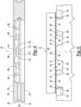
- the second mounting flange flank 118 may be disposed in a nonparallel and non-perpendicular relationship with the first mounting flange flank 116. As is best shown in Figure 3 , the second mounting flange flank 118 faces toward and engages a different mounting boss 44 of the wheel hub 20 than the first mounting flange flank 116. For instance, the second mounting flange flank 118 may face toward and may engage or contact a flank of a different mounting boss 44. In some configurations, the second mounting flange flank 118 faces toward and engages or contacts the second flank 64 of a second mounting boss 44.
- the first mounting flange flank 116 and the second mounting flange flank 118 are tapered.
- the tapering can be provided in multiple directions.
- the first mounting flange flank 116 and the second mounting flange flank 118 may be axially tapered and radially tapered.
- first mounting flange flank 116 and the second mounting flange flank 118 are axially tapered or tapered in a direction that extends along or parallel to the axis 30.
- first mounting flange flank 116 and the second mounting flange flank 118 are axially tapered such that the first mounting flange flank 116 and the second mounting flange flank 118 extend farther apart in a direction that extends from the first mounting flange side 112 toward the second mounting flange side 114.
- the first mounting flange flank 116 and the second mounting flange flank 118 may be axially tapered such that the first mounting flange flank 116 and the second mounting flange flank 118 become progressively further apart as the distance from the first mounting flange side 112 increases.
- the first mounting flange flank 116 and the second mounting flange flank 118 are tapered in the same manner or at the same angle but in opposite directions. Providing one or more axially tapered mounting flange flanks sets the axial positioning of the brake rotor 22 with respect to the wheel hub 20, limits axial movement of the brake rotor 22 along the wheel hub 20 toward the wheel mounting flange 42, helps resist rotation of the brake rotor 22 with respect to the wheel hub 20, or combinations thereof.
- first mounting flange flank 116 and the second mounting flange flank 118 are tapered with respect to each other in a direction that extends away from the axis 30 or tapered with respect to a radial line that extends from the axis 30 such that the first mounting flange flank 116 and the second mounting flange flank 118 extend farther apart in a direction that extends from the inner mounting flange side 110 away from the axis 30.
- first mounting flange flank 116 may be radially tapered such that the first mounting flange flank 116 and the second mounting flange flank 118 become progressively further apart as the distance from the axis 30 increases.
- the wheel hub 20 and the brake rotor 22 may cooperate to form or define a gap 120.
- the gap 120 may extend axially from a connecting surface 46 of the wheel hub 20 to the first mounting flange side 112 of the mounting flange 86 of the brake rotor 22.
- the gap 120 may also extend from the first flank connecting surface 66 of a first mounting boss 44 to the second flank connecting surface 68 of a second mounting boss 44.
- the brake rotor 22 may be spaced apart from the flank connecting surfaces.
- the mounting flange 86 of the brake rotor 22 may be spaced apart from the first flank connecting surface 66 of the first mounting boss 44 and the second flank connecting surface 68 of the second mounting boss 44.
- the fastener 24 secures the brake rotor 22 to the wheel hub 20.
- the fastener 24 may inhibit axial movement of the brake rotor 22 away from the connecting surface 46 and thus inhibit removal of the brake rotor 22 from the wheel hub 20.
- the fastener 24 is secured to the wheel hub 20.
- the fastener 24 may be secured to the wheel hub 20 such that the wheel hub 20, the brake rotor 22, and the fastener 24 are rotatable together about the axis 30.
- the fastener 24 may have any suitable configuration.
- the fastener 24 may be configured as a clip, washer, snap ring, or the like.
- the fastener 24 may be received in a groove 130 in the wheel hub 20 that extends toward the axis 30.
- the groove 130 may extend from the second connecting surface 48 toward the axis 30.
- the groove 130 may extend around or encircle the axis 30.
- the fastener 24 may engage or contact the second mounting flange side 114 of the mounting flange 86 of the brake rotor 22.
- the fastener 24 may extend away from the axis 30 and out of the groove 130 to contact or engage the second mounting flange side 114.
- the fastener 24 may be spaced apart from the mounting bosses 44 of the wheel hub 20.
- the fastener 24 may be spaced apart from the outboard side 60 of one or more mounting bosses 44.
- the fastener 24 may include a plurality of detectable features 140.
- the detectable features 140 may be arranged around the axis 30 in a repeating pattern or equally spaced angular intervals.
- a detectable feature 140 may be configured as a tooth that protrudes from the fastener 24 or a recess or indentation that extends into or through the fastener 24.
- Providing the fastener 24 with detectable features 140 may allow the fastener 24 to be configured as a tone ring that may be detectable by a sensor to provide a signal indicative of the rotational speed or velocity of the wheel hub 20 and hence the rotational velocity of a corresponding vehicle wheel.
- the fastener 24 is secured to the wheel hub 20 such that the fastener 24 is inhibiting from rotating about the axis 30 with respect to the wheel hub 20.
- the fastener 24 may be non-rotatably secured in any suitable manner.
- the fastener 24 may be received in the groove 130 with an interference fit, secured with a fastener that is a separate component, or the like.
- the fastener 24 includes an anti-rotation feature 150.
- the anti-rotation feature 150 may limit or inhibit rotation of the fastener 24 about the axis 30 with respect to the wheel hub 20.
- the anti-rotation feature 150 may extend toward the axis 30, such as from a side of the fastener 24 that faces toward the axis 30, and into a recess 152 that extends toward the axis 30 from a bottom wall or bottom side 154 of the groove 130. It is also contemplated that the fastener 24 may be secured to the brake rotor 22 to inhibit rotation of the fastener 24 about the axis 30 in addition to being secured to the wheel hub 20 or as an alternative to being secured to the wheel hub 20.
- the present invention allows a brake rotor to be mounted to a wheel hub without threaded fastener such as bolts.
- a bolted connection between a brake rotor and a wheel hub may be less durable than a non-bolted connection.
- the temperature of the brake rotor increases during brake application. Increased temperature causes thermal expansion of the brake rotor and conduction of thermal energy to holes or openings in the brake rotor that receive a threaded fastener.
- Thermal expansion of a bolted connection increases localized stresses and can result in cracking of the brake rotor, such as the formation of cracks that are disposed proximate or extend from the hole or opening that receives the fastener, which in turn can reduce brake rotor service life.
- the present invention may eliminate the use of individual mounting clips that are used to secure the brake rotor to individual mounting bosses of the wheel hub, thereby reducing assembly time and complexity.
- the present invention may eliminate the use of threaded fasteners that are used to attach each mounting clip to a different mounting boss, thereby also reduce assembly time and complexity.
- the present invention may also help reliably and stably position a brake rotor directly upon a wheel hub without intervening components and may secure the brake rotor to the wheel hub with a single fastener, which may help reduce assembly time.
Landscapes
- Engineering & Computer Science (AREA)
- Mechanical Engineering (AREA)
- General Engineering & Computer Science (AREA)
- Transportation (AREA)
- Braking Arrangements (AREA)
Applications Claiming Priority (1)
| Application Number | Priority Date | Filing Date | Title |
|---|---|---|---|
| US18/521,342 US20250170854A1 (en) | 2023-11-28 | 2023-11-28 | Wheel hub and brake rotor assembly |
Publications (1)
| Publication Number | Publication Date |
|---|---|
| EP4567293A1 true EP4567293A1 (de) | 2025-06-11 |
Family
ID=93704640
Family Applications (1)
| Application Number | Title | Priority Date | Filing Date |
|---|---|---|---|
| EP24215830.1A Pending EP4567293A1 (de) | 2023-11-28 | 2024-11-27 | Radnabe und bremsrotoranordnung |
Country Status (3)
| Country | Link |
|---|---|
| US (1) | US20250170854A1 (de) |
| EP (1) | EP4567293A1 (de) |
| CN (1) | CN120056644A (de) |
Citations (4)
| Publication number | Priority date | Publication date | Assignee | Title |
|---|---|---|---|---|
| US20080149435A1 (en) * | 2005-04-01 | 2008-06-26 | Performance Friction Corporation | Direct Drive Braking System Including an Integrated Package Bearing |
| US20130001029A1 (en) * | 2011-06-29 | 2013-01-03 | Arvinmeritor Technology, Llc | Brake Assembly Having a Mounting Clip |
| EP2639472A1 (de) * | 2012-03-12 | 2013-09-18 | PE Automotive GmbH & Co. KG | Verschleißblech für eine Bremsscheibe |
| US11629765B2 (en) | 2020-05-15 | 2023-04-18 | Arvinmeritor Technology, Llc | Brake rotor |
Family Cites Families (12)
| Publication number | Priority date | Publication date | Assignee | Title |
|---|---|---|---|---|
| FR2799520B1 (fr) * | 1999-10-08 | 2002-01-25 | Messier Bugatti | Dispositif de fixaion axiale d'un disque ventile de freinage sur le moyeu d'une roue d'un vehicule automobile |
| US8950556B2 (en) * | 2011-03-31 | 2015-02-10 | Gunite Corporation | Disk brake hub assembly |
| US9897154B2 (en) * | 2011-03-31 | 2018-02-20 | Gunite Corporation | Disk brake hub assembly |
| US10215245B2 (en) * | 2015-09-16 | 2019-02-26 | Performance Friction Corporation | Floating rotor disc with compressible retention ring fastener |
| US9964164B1 (en) * | 2017-02-01 | 2018-05-08 | Consolidated Metco, Inc. | Disc brake tone ring |
| US10495162B2 (en) * | 2017-09-11 | 2019-12-03 | Consolidated Metco, Inc. | Disc brake rotor assembly |
| US10837509B2 (en) * | 2018-07-20 | 2020-11-17 | Bendix Spicer Foundation Brake Llc | Brake disc mounting arrangement |
| US10830295B2 (en) * | 2018-07-20 | 2020-11-10 | Bendix Spicer Foundation Brake Llc | Brake disc mounting arrangement |
| US20200096064A1 (en) * | 2018-09-26 | 2020-03-26 | Goodrich Corporation | Friction discs with angled stator lugs |
| US11920647B2 (en) * | 2020-04-13 | 2024-03-05 | Consolidated Metco, Inc. | Disc brake rotor assembly |
| USD1019492S1 (en) * | 2022-01-10 | 2024-03-26 | Fisher & Paykel Appliances Limited | Rotor hub |
| US20230383804A1 (en) * | 2022-05-27 | 2023-11-30 | Arvinmeritor Technology, Llc | Brake rotor assembly and method of assembly |
-
2023
- 2023-11-28 US US18/521,342 patent/US20250170854A1/en active Pending
-
2024
- 2024-11-20 CN CN202411663892.3A patent/CN120056644A/zh active Pending
- 2024-11-27 EP EP24215830.1A patent/EP4567293A1/de active Pending
Patent Citations (4)
| Publication number | Priority date | Publication date | Assignee | Title |
|---|---|---|---|---|
| US20080149435A1 (en) * | 2005-04-01 | 2008-06-26 | Performance Friction Corporation | Direct Drive Braking System Including an Integrated Package Bearing |
| US20130001029A1 (en) * | 2011-06-29 | 2013-01-03 | Arvinmeritor Technology, Llc | Brake Assembly Having a Mounting Clip |
| EP2639472A1 (de) * | 2012-03-12 | 2013-09-18 | PE Automotive GmbH & Co. KG | Verschleißblech für eine Bremsscheibe |
| US11629765B2 (en) | 2020-05-15 | 2023-04-18 | Arvinmeritor Technology, Llc | Brake rotor |
Also Published As
| Publication number | Publication date |
|---|---|
| CN120056644A (zh) | 2025-05-30 |
| US20250170854A1 (en) | 2025-05-29 |
Similar Documents
| Publication | Publication Date | Title |
|---|---|---|
| EP3910210B1 (de) | Bremsrotor | |
| US7850251B1 (en) | Wheel hub and brake rotor assembly | |
| US20110127826A1 (en) | Hub and brake assembly | |
| CN111163981B (zh) | 用于防抱死制动系统的调谐环安装结构和制造方法 | |
| US9303705B2 (en) | Brake disc and mounting arrangement for a brake disc | |
| EP0398092A1 (de) | Träger zur Drehmomentübertragung für Räder mit Bremsdrehmomentantrieb | |
| US11585387B2 (en) | Rotor drive key assembly | |
| US20160258500A1 (en) | Brake Disc Mounting Arrangement | |
| US20200102992A1 (en) | Vehicle braking system | |
| US10899174B2 (en) | Wheel end assembly having a compression ring and method of assembly | |
| CN115366578B (zh) | 具有制动鼓的车桥组件 | |
| US20060113153A1 (en) | Brake disc assembly | |
| EP4567293A1 (de) | Radnabe und bremsrotoranordnung | |
| EP3398834B1 (de) | Radendanordnung mit deflektor | |
| ITTO960387A1 (it) | Gruppo cuscinetto/organo frenante perfezionato per autotrazione, prov visto di un elemento di collegamento intermedio tra cuscinetto ed orga | |
| EP3398835B1 (de) | Radendanordnung mit einem kompressionsring und verfahren zur montage | |
| EP4010202B1 (de) | Radnabe mit integriertem kreisförmigem bremselement | |
| EP1652690A2 (de) | Radnabe für Eckanordnung | |
| EP4063144A1 (de) | Radendanordnung und wartungsverfahren | |
| CN213628604U (zh) | 一种带防翘销的曲面制动盘 | |
| CA3133368C (en) | Hubcap for heavy-duty vehicles | |
| CN213899686U (zh) | 一种具有主辅散热槽的制动盘 | |
| WO2026064615A1 (en) | Wheel hub brake rotor |
Legal Events
| Date | Code | Title | Description |
|---|---|---|---|
| PUAI | Public reference made under article 153(3) epc to a published international application that has entered the european phase |
Free format text: ORIGINAL CODE: 0009012 |
|
| STAA | Information on the status of an ep patent application or granted ep patent |
Free format text: STATUS: THE APPLICATION HAS BEEN PUBLISHED |
|
| AK | Designated contracting states |
Kind code of ref document: A1 Designated state(s): AL AT BE BG CH CY CZ DE DK EE ES FI FR GB GR HR HU IE IS IT LI LT LU LV MC ME MK MT NL NO PL PT RO RS SE SI SK SM TR |
|
| STAA | Information on the status of an ep patent application or granted ep patent |
Free format text: STATUS: REQUEST FOR EXAMINATION WAS MADE |
|
| 17P | Request for examination filed |
Effective date: 20251211 |