EP4566982A1 - Füllorgan mit vakuumeinrichtung - Google Patents
Füllorgan mit vakuumeinrichtung Download PDFInfo
- Publication number
- EP4566982A1 EP4566982A1 EP24215689.1A EP24215689A EP4566982A1 EP 4566982 A1 EP4566982 A1 EP 4566982A1 EP 24215689 A EP24215689 A EP 24215689A EP 4566982 A1 EP4566982 A1 EP 4566982A1
- Authority
- EP
- European Patent Office
- Prior art keywords
- filling
- vacuum
- valve
- product
- channel
- Prior art date
- Legal status (The legal status is an assumption and is not a legal conclusion. Google has not performed a legal analysis and makes no representation as to the accuracy of the status listed.)
- Pending
Links
Images

Classifications
-
- B—PERFORMING OPERATIONS; TRANSPORTING
- B67—OPENING, CLOSING OR CLEANING BOTTLES, JARS OR SIMILAR CONTAINERS; LIQUID HANDLING
- B67C—CLEANING, FILLING WITH LIQUIDS OR SEMILIQUIDS, OR EMPTYING, OF BOTTLES, JARS, CANS, CASKS, BARRELS, OR SIMILAR CONTAINERS, NOT OTHERWISE PROVIDED FOR; FUNNELS
- B67C3/00—Bottling liquids or semiliquids; Filling jars or cans with liquids or semiliquids using bottling or like apparatus; Filling casks or barrels with liquids or semiliquids
- B67C3/02—Bottling liquids or semiliquids; Filling jars or cans with liquids or semiliquids using bottling or like apparatus
- B67C3/06—Bottling liquids or semiliquids; Filling jars or cans with liquids or semiliquids using bottling or like apparatus using counterpressure, i.e. filling while the container is under pressure
- B67C3/12—Pressure-control devices
-
- B—PERFORMING OPERATIONS; TRANSPORTING
- B67—OPENING, CLOSING OR CLEANING BOTTLES, JARS OR SIMILAR CONTAINERS; LIQUID HANDLING
- B67C—CLEANING, FILLING WITH LIQUIDS OR SEMILIQUIDS, OR EMPTYING, OF BOTTLES, JARS, CANS, CASKS, BARRELS, OR SIMILAR CONTAINERS, NOT OTHERWISE PROVIDED FOR; FUNNELS
- B67C3/00—Bottling liquids or semiliquids; Filling jars or cans with liquids or semiliquids using bottling or like apparatus; Filling casks or barrels with liquids or semiliquids
- B67C3/02—Bottling liquids or semiliquids; Filling jars or cans with liquids or semiliquids using bottling or like apparatus
- B67C3/06—Bottling liquids or semiliquids; Filling jars or cans with liquids or semiliquids using bottling or like apparatus using counterpressure, i.e. filling while the container is under pressure
- B67C3/10—Bottling liquids or semiliquids; Filling jars or cans with liquids or semiliquids using bottling or like apparatus using counterpressure, i.e. filling while the container is under pressure preliminary filling with inert gases, e.g. carbon dioxide
-
- B—PERFORMING OPERATIONS; TRANSPORTING
- B67—OPENING, CLOSING OR CLEANING BOTTLES, JARS OR SIMILAR CONTAINERS; LIQUID HANDLING
- B67C—CLEANING, FILLING WITH LIQUIDS OR SEMILIQUIDS, OR EMPTYING, OF BOTTLES, JARS, CANS, CASKS, BARRELS, OR SIMILAR CONTAINERS, NOT OTHERWISE PROVIDED FOR; FUNNELS
- B67C3/00—Bottling liquids or semiliquids; Filling jars or cans with liquids or semiliquids using bottling or like apparatus; Filling casks or barrels with liquids or semiliquids
- B67C3/02—Bottling liquids or semiliquids; Filling jars or cans with liquids or semiliquids using bottling or like apparatus
- B67C3/22—Details
-
- B—PERFORMING OPERATIONS; TRANSPORTING
- B67—OPENING, CLOSING OR CLEANING BOTTLES, JARS OR SIMILAR CONTAINERS; LIQUID HANDLING
- B67C—CLEANING, FILLING WITH LIQUIDS OR SEMILIQUIDS, OR EMPTYING, OF BOTTLES, JARS, CANS, CASKS, BARRELS, OR SIMILAR CONTAINERS, NOT OTHERWISE PROVIDED FOR; FUNNELS
- B67C3/00—Bottling liquids or semiliquids; Filling jars or cans with liquids or semiliquids using bottling or like apparatus; Filling casks or barrels with liquids or semiliquids
- B67C3/02—Bottling liquids or semiliquids; Filling jars or cans with liquids or semiliquids using bottling or like apparatus
- B67C3/22—Details
- B67C3/26—Filling-heads; Means for engaging filling-heads with bottle necks
-
- B—PERFORMING OPERATIONS; TRANSPORTING
- B67—OPENING, CLOSING OR CLEANING BOTTLES, JARS OR SIMILAR CONTAINERS; LIQUID HANDLING
- B67C—CLEANING, FILLING WITH LIQUIDS OR SEMILIQUIDS, OR EMPTYING, OF BOTTLES, JARS, CANS, CASKS, BARRELS, OR SIMILAR CONTAINERS, NOT OTHERWISE PROVIDED FOR; FUNNELS
- B67C3/00—Bottling liquids or semiliquids; Filling jars or cans with liquids or semiliquids using bottling or like apparatus; Filling casks or barrels with liquids or semiliquids
- B67C3/02—Bottling liquids or semiliquids; Filling jars or cans with liquids or semiliquids using bottling or like apparatus
- B67C3/22—Details
- B67C3/26—Filling-heads; Means for engaging filling-heads with bottle necks
- B67C3/2614—Filling-heads; Means for engaging filling-heads with bottle necks specially adapted for counter-pressure filling
-
- B—PERFORMING OPERATIONS; TRANSPORTING
- B67—OPENING, CLOSING OR CLEANING BOTTLES, JARS OR SIMILAR CONTAINERS; LIQUID HANDLING
- B67C—CLEANING, FILLING WITH LIQUIDS OR SEMILIQUIDS, OR EMPTYING, OF BOTTLES, JARS, CANS, CASKS, BARRELS, OR SIMILAR CONTAINERS, NOT OTHERWISE PROVIDED FOR; FUNNELS
- B67C3/00—Bottling liquids or semiliquids; Filling jars or cans with liquids or semiliquids using bottling or like apparatus; Filling casks or barrels with liquids or semiliquids
- B67C3/02—Bottling liquids or semiliquids; Filling jars or cans with liquids or semiliquids using bottling or like apparatus
- B67C3/22—Details
- B67C3/26—Filling-heads; Means for engaging filling-heads with bottle necks
- B67C3/2614—Filling-heads; Means for engaging filling-heads with bottle necks specially adapted for counter-pressure filling
- B67C3/2625—Filling-heads; Means for engaging filling-heads with bottle necks specially adapted for counter-pressure filling the liquid valve being opened automatically when a given counter-pressure is obtained in the container to be filled
- B67C3/2631—Filling-heads; Means for engaging filling-heads with bottle necks specially adapted for counter-pressure filling the liquid valve being opened automatically when a given counter-pressure is obtained in the container to be filled and the filling operation stopping when probes, e.g. electrical or optical probes, sense the wanted liquid level
-
- B—PERFORMING OPERATIONS; TRANSPORTING
- B67—OPENING, CLOSING OR CLEANING BOTTLES, JARS OR SIMILAR CONTAINERS; LIQUID HANDLING
- B67C—CLEANING, FILLING WITH LIQUIDS OR SEMILIQUIDS, OR EMPTYING, OF BOTTLES, JARS, CANS, CASKS, BARRELS, OR SIMILAR CONTAINERS, NOT OTHERWISE PROVIDED FOR; FUNNELS
- B67C3/00—Bottling liquids or semiliquids; Filling jars or cans with liquids or semiliquids using bottling or like apparatus; Filling casks or barrels with liquids or semiliquids
- B67C3/02—Bottling liquids or semiliquids; Filling jars or cans with liquids or semiliquids using bottling or like apparatus
- B67C3/22—Details
- B67C3/26—Filling-heads; Means for engaging filling-heads with bottle necks
- B67C2003/2671—Means for preventing foaming of the liquid
Definitions
- the present invention relates to a filling device for filling a container with a filling product, preferably a beverage, comprising a vacuum device.
- a vacuum is not understood to mean a complete vacuum in the physical sense, but rather the reduction of the pressure in the container below atmospheric pressure, followed by purging with a process gas such as CO2 .
- the container In a multi-stage evacuation process, the container is first evacuated, then purged with a process gas such as CO2 , and then evacuated again. In addition to such a double evacuation, a triple evacuation is also possible and is practiced. How often the container is evacuated depends primarily on the beverage and the required residual oxygen quality. CO2 consumption, process time, and the quality of the pre-vacuum also play a role.
- a process gas such as CO2
- the container and the filling device equipped with a vacuum function are connected in a fluid-tight and gas-tight manner.
- the filling device includes an evacuation channel through which the gas atmosphere is extracted from the container, and a vacuum valve that opens and closes the connection between the container and the vacuum.
- Carbonated beverages i.e., those containing CO2
- the container-side opening of the vacuum channel can be located centrally in the filling valve or at the filling valve outlet, approximately between a seal to the product chamber and the valve outlet. If the filling device includes a central gas pipe, for example, for purging the container and/or for removing gas displaced during filling, the vacuum channel is usually installed on the side of the valve outlet.
- a filling element constructed in this way comprising a lateral suction channel and a vacuum device for pre-evacuation of the container, is known, for example, from DE 10 2022 102 536 A1 out.
- the position of the vacuum opening in the valve outlet, which is connected to a vacuum channel up to a switching valve, is not optimal for several reasons.
- the vacuum channel can cause flow losses when generating the vacuum in the container.
- the vacuum channel defines a dead space that must be pre-pressurized for filling and later relieved, thereby increasing the CO2 consumption of the filling device.
- the product When filling the container with the filling product, the product flows over the vacuum opening of the vacuum channel. This can impair the filling performance, for example, due to increased foam formation. Therefore, the bore diameter of the vacuum opening must not be too large. During filling, filling product can also be forced into the vacuum channel, leading to product loss when the pressure is released after the filling process.
- An object of the invention is to provide an improved filling device for filling a container with a filling product, in particular a beverage.
- the filling device serves to fill a container with a filling product.
- the filling device is particularly preferably used in a beverage filling system, in particular for filling oxygen-sensitive beverages such as beer, juice, soft drinks, smoothies, dairy products, and the like.
- the filling device has a product outlet for introducing the filling product into the container and a product channel configured to guide or transport the filling product to the product outlet.
- the filling device further has a filling valve configured to open the product channel and close it at a closing contour of the filling valve.
- the closing contour of the filling valve designates the one or more points at which the filling valve, when closed, blocks the flow of the filling product through the product channel.
- the closing contour of the filling valve thus defines a point, a line, or a section in the product channel.
- the filling device further comprises a vacuum device configured to evacuate the container.
- the vacuum device comprises a vacuum supply for generating the vacuum, a vacuum channel connecting the vacuum supply to the product channel (i.e., fluidly connecting the vacuum supply and the product channel), and a vacuum valve configured to open the vacuum channel and close it at a closing contour of the vacuum valve.
- the closing contour of the vacuum valve designates one or more locations at which the vacuum valve, when closed, blocks the gas flow through the vacuum channel occurring during evacuation.
- the closing contour of the vacuum valve thus defines a point, a line, or a section in the vacuum channel.
- the vacuum valve is arranged in the area of or near the product channel. In other words, the vacuum valve is located at or directly adjacent to the product channel.
- the vacuum valve is particularly preferably arranged and configured such that its closing contour is located in the region of the product channel, preferably at least partially directly on the product channel.
- Dead space in this context refers to any section of the vacuum channel between the product channel and the closing contour of the vacuum valve. Minimizing the dead space in the vacuum channel reduces any flow losses during the evacuation of the container, allowing for a significantly faster and better vacuum. This optimizes the vacuum buildup process in the container.
- the optimization of the vacuum build-up in the container can be further supported by a comparatively large cross-section of the vacuum channel, which is possible due to the position and nature of the vacuum valve according to the invention.
- the vacuum valve comprises a vacuum valve element displaceable in an axial direction of the vacuum valve and a vacuum valve seat cooperating with the vacuum valve element.
- the closing contour of the vacuum valve is defined by the contact points of the vacuum valve element with the vacuum valve seat in the closed position of the vacuum valve.
- the vacuum valve element and/or the vacuum valve seat can be equipped with a vacuum valve seal.
- the vacuum valve element forms part of the wall defining the product channel in the closed state of the vacuum valve, i.e. the vacuum valve element comes into contact with the filling product on the side of the product channel during the filling process, whereby any dead space in the vacuum channel is essentially completely eliminated and thus the process of vacuum buildup in the container and the flow behavior of the filling product in the product channel are further optimized.
- the vacuum valve element is flattened on the side downstream of the vacuum valve seat, in particular flatly rounded, in order to further improve the flow behavior of the filling product in the product channel.
- the vacuum valve element is arranged inside the vacuum channel.
- the vacuum valve element is displaceable in the direction of extension of the vacuum channel, similar to a valve cone.
- the vacuum valve element is protected from external influences and thus contributes to the design of a mechanically simple and reliable vacuum valve.
- the vacuum valve element forms part of the outer wall defining the vacuum channel when the vacuum valve is open.
- the vacuum valve element is not an element located inside the vacuum channel that gives the vacuum channel a ring shape, at least in sections. Rather, The vacuum valve element at least partially defines the outer contour of the vacuum channel, allowing the vacuum valve to be implemented with few components. This also allows the cross-section of the vacuum channel to be maximized, allowing for particularly rapid evacuation of the container.
- the vacuum valve is arranged such that its closing contour is located partially or completely downstream of the closing contour of the filling valve (seen along the product flow), in particular in the region of the product outlet or directly at the product outlet, whereby the process of vacuum build-up in the container and the flow behavior of the filling product in the product channel are further optimized.
- the vacuum valve is designed as a shut-off valve
- the filling valve is preferably designed as a control valve, in particular a proportional valve, to enable gradual (in particular stepless) adjustment of the product channel cross-section and thus of the filling product flow. Control of intermediate positions with the vacuum valve is generally not required.
- the filling valve has a filling valve cone that is displaceable in an axial direction of the filling valve and a filling valve seat that interacts with the filling valve cone.
- the closing contour of the filling valve is defined by the contact points of the filling valve cone with the filling valve seat in the closed position of the filling valve.
- the filling valve cone and/or the filling valve seat can be equipped with a filling valve seal.
- the filling device preferably has a central probe, preferably a short-circuit probe, which runs centrally through the filling valve cone and extends into the interior of the container during container treatment.
- the probe can be used to shut off the filling process when a defined fluid level in the container is reached.
- the product outlet can be brought into fluid-tight and gas-tight contact with a container mouth of the container in order to be able to treat the container safely and reliably, in particular to evacuate it.
- the filling device has a centering bell for centering the container mouth relative to the product outlet.
- the container mouth is used for container treatment, comprising at least an evacuation of the container and filling of the container with the filling product, pressed/pressed against the centering bell.
- the Figure 1 is a schematic representation, partly as a sectional view, of a filling device 1.
- the filling device 1 is for introducing a filling product into a container 2, the container mouth 2a of which is in the Figure 1 is shown.
- the filling device 1 is particularly preferably used in a beverage filling plant, for example for filling water (still or carbonated), beer, juice, soft drinks, smoothies, dairy products, and the like.
- the container 2 is brought into fluid-tight and gas-tight connection with a product outlet 10 of the filling element 1.
- a process gas preferably CO 2
- the container 2 and/or the filling element 1 are moved toward one another such that the container mouth 2a is pressed directly or indirectly against the product outlet 10 of the filling element 1.
- the filling element 1 can, as shown in the present embodiment, comprise a centering bell 11, which helps to bring the product outlet 10 and the container 2 into the desired relative position and to connect them in a fluid-tight and gas-tight manner.
- the filling device 1 has a product channel 12 which is designed to transport the filling product to the container 2 and to introduce it into the container 2 via the product outlet 10.
- the product channel 12 is formed from a product supply (in the Figure 1 not shown), such as a product tank, with the filling product.
- a filling valve 20 is installed, which comprises a filling valve cone 21 and a filling valve seat 22 cooperating with the filling valve cone 21.
- the filling valve cone 21 is moved along an axial direction Af of the filling valve 20 via an actuator (in the Figure 1 not shown) to thereby close and open the product channel.
- the filling valve cone 21 and/or the filling valve seat 22 can be equipped with a filling valve seal 23.
- the filling valve 20 is designed as a control valve, in particular a proportional valve, in order to enable a gradual (preferably stepless) adjustment of the product channel cross-section and thus of the filling product flow.
- the filling device 1 further comprises a vacuum device 30 which is designed to evacuate the container 2 before filling it with the filling product.
- the vacuum device 30 has a vacuum supply 31 configured to generate or otherwise provide a vacuum.
- the vacuum supply may comprise a corresponding vacuum pump, which may be configured, for example, as a liquid ring pump or a dry-running screw vacuum pump.
- the vacuum device 30 further comprises a vacuum channel 32 which connects the vacuum supply 31 to the product channel 12, preferably in the region of the product outlet 10, ie downstream of the filling valve 20 or the closing contour Sf of the filling valve 20 between Filling valve seat 22 and filling valve cone 21.
- the closing contour Sf of the filling valve 20 is defined by the contact points of the filling valve cone 21 with the filling valve seat 22 in the closed position of the filling valve 20.
- the vacuum device 30 further comprises a vacuum valve 33 configured to switch, i.e., open and close, the vacuum channel 32 in the region of the product channel 12.
- the vacuum valve 33 is installed laterally directly next to the product channel 12, whereby essentially no channel or dead space remains between the product channel 12 and the vacuum valve 33, i.e., the vacuum supply shutoff 31.
- "Dead space” in this context refers to any section of the vacuum channel 32 between the product channel 12 and the closing contour Sv of the vacuum valve 33.
- the vacuum valve 33 comprises according to the embodiment of the Figure 1 a vacuum valve element 34 and a vacuum valve seat 35 cooperating with the vacuum valve element 34.
- the vacuum valve element 34 is movable along an axial direction Av of the vacuum valve 33, which preferably runs at an oblique angle to the axial direction Af of the filling valve 20, via an actuator (in the Figure 1 not shown) to thereby close and open the vacuum channel 32.
- the closing contour Sv of the vacuum valve 33 is defined by the contact points of the vacuum valve element 34 with the vacuum valve seat 35 in the closed position of the vacuum valve 33.
- the vacuum valve element 34 and/or the vacuum valve seat 35 can be equipped with a vacuum valve seal 36.
- the vacuum valve 33 is preferably designed as a shut-off valve or switching valve that can fully open and completely close the vacuum channel 32 in a binary manner. In contrast to the filling valve 20, the control of intermediate positions is generally not required.
- the vacuum valve element 34 preferably attaches directly to the product channel 12, preferably directly to the product outlet 10 of the filling device 1, and closes there.
- the vacuum valve element 34 can be flattened, in particular flatly rounded, on the side downstream of the vacuum valve seat 35, whereby the shape of the vacuum valve element 34 differs from the conical shape of the filling valve cone 21.
- the vacuum valve 33 arranged and designed in this way allows a comparatively large cross-section of the vacuum channel 32, since the vacuum valve element 34, in the closed state, directly adjoins the product channel 12 and thus at least partially forms a wall for the product channel 12, whereby the product flow in the product channel 12 is not or only slightly disturbed.
- the process step of building up the vacuum in the container 2 can be optimized.
- the filling device can be equipped with a central probe 40, preferably a short-circuit probe, which runs centrally through the filling valve cone 21 and extends into the interior of the container.
- the probe 40 serves to shut off the filling process when a defined fluid level is reached in the container 2.
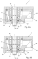
- the Figures 2A and 2B show an alternative embodiment of the filling element 1, in particular with regard to the design of the vacuum valve 33' of the vacuum device 30.
- the Figure 2A shows the vacuum valve 33' in a closed position
- the Figure 2B shows the vacuum valve 33' in an open position.
- the following description focuses on the vacuum valve 33 ⁇ , the remaining components, including the filling valve 20 and the vacuum supply 31, being identical or similar to the embodiment of the Figure 1 can be executed.
- the vacuum valve 33' according to the embodiment of the Figures 2A and 2B in turn comprises a movable vacuum valve element 34' and a vacuum valve seat 35' that interacts with the vacuum valve element 34'.
- the vacuum valve element 34' is displaceable along an axial direction Av of the vacuum valve 33' via an actuator in order to close and open the vacuum channel 32.
- the axial direction Av of the vacuum valve 33' here runs parallel to the axial direction Af of the filling valve 20.
- the vacuum valve element 34 ⁇ is, in contrast to the embodiment of the Figure 1 not arranged inside the vacuum channel 32, but forms part of the wall forming the vacuum channel 32. This wall is displaceable in the axial direction Av of the vacuum valve 33 ⁇ , which here coincides with the direction of gravity, whereby in the position of the Figure 2B the vacuum channel 32 is released.
- the vacuum valve element 34' is therefore according to this embodiment not an element which is located inside the vacuum channel 32, which gives the vacuum channel 32 at least in sections a ring shape and along its is displaceable in the direction of extension. Rather, the vacuum valve element 34' at least partially defines the outer contour of the vacuum channel 32.
- the switching of the vacuum valve 33' i.e., the closing and opening, again takes place directly at the product channel 12, so that any dead space in the vacuum channel 32 downstream of the vacuum valve 33 is minimized, and in this case, completely eliminated.
- the closing contour Sv of the vacuum valve 33' is located directly at the product channel 12.
- the vacuum valve element 34' and/or the vacuum valve seat 35' can be equipped with a vacuum valve seal 36.
- the vacuum valve 33' is also preferably designed as a shut-off valve or switching valve that can completely open and completely close the vacuum channel 32 in a binary manner. In contrast to the filling valve 20, the control of intermediate positions is generally not necessary.
- Minimizing or even eliminating the dead space between the product channel 12 and the closing contour Sv of the vacuum valve 33, 33' reduces any flow losses during the evacuation of the container 2, thereby enabling a significantly faster and better vacuum. This is further supported by a comparatively large cross-section of the vacuum channel 32, which is made possible by the arrangement, position, and design of the vacuum valve 33, 33'.
Landscapes
- Chemical & Material Sciences (AREA)
- Chemical Kinetics & Catalysis (AREA)
- Filling Of Jars Or Cans And Processes For Cleaning And Sealing Jars (AREA)
Abstract
Füllorgan (1) zum Befüllen eines Behälters (2) mit einem Füllprodukt, vorzugsweise in einer Getränkeabfüllanlage, wobei das Füllorgan (1) aufweist: einen Produktauslass (10) zum Einleiten des Füllprodukts in den Behälter (2) sowie einen Produktkanal (12), der eingerichtet ist, um das Füllprodukt zum Produktauslass (10) zu leiten; ein Füllventil (20), das eingerichtet ist, um den Produktkanal (12) zu öffnen und an einer Schließkontur (Sf) des Füllventils (20) zu schließen; und eine Vakuumeinrichtung (30), die eingerichtet ist, um den Behälter (2) zu evakuieren, wobei die Vakuumeinrichtung (30) eine Vakuumbereitstellung (31) zur Bereitstellung des Vakuums, einen Vakuumkanal (32), der die Vakuumbereitstellung (31) mit dem Produktkanal (12) verbindet, und ein Vakuumventil (33, 33') aufweist, das eingerichtet ist, um den Vakuumkanal (32) zu öffnen und an einer Schließkontur (Sv) des Vakuumventils (20) zu schließen; dadurch gekennzeichnet, dass das Vakuumventil (33, 33`) im Bereich des Produktkanals (12) angeordnet ist.
Description
- Die vorliegende Erfindung betrifft ein Füllorgan zum Befüllen eines Behälters mit einem Füllprodukt, vorzugsweise einem Getränk, umfassend eine Vakuumeinrichtung.
- Bei der Abfüllung von Getränken, insbesondere sauerstoffempfindlichen Getränken, ist es üblich, in den Behältern vor dem Befüllen mit dem Produkt den Sauerstoff zu reduzieren beziehungsweise die Behälter von Sauerstoff zu befreien. Dies kann durch einmaliges oder mehrmaliges Evakuieren der Behälter erfolgen. Voraussetzung sind vakuumstabile Behälter, beispielsweise Glasflaschen. Vor der Befüllung wird die Luft mithilfe von Vakuum aus dem Behälter "gesaugt" (evakuiert). Je schneller und je tiefer das Vakuum ist, umso effizienter ist der Prozess. Dabei wird unter einem Vakuum kein im physikalischen Sinne vollständiges Vakuum verstanden, sondern die Reduzierung des Drucks in dem Behälter unter Atmosphärendruck unter anschließendem Spülen mit einem Prozessgas wie CO2.
- Im Fall eines mehrstufigen Evakuierungsprozesses wird der Behälter zunächst evakuiert, anschließend mit dem Prozessgas wie CO2 gespült und daran anschließend erneut evakuiert. Neben einer solchen zweifachen Evakuierung ist auch eine dreifache Evakuierung möglich und wird auch umgesetzt. Wie oft der Behälter evakuiert wird, ist primär abhängig vom Getränk und welche Restsauerstoffqualität benötigt wird. Auch der CO2-Verbrauch, die Prozesszeit und Güte des Vorvakuums spielen eine Rolle.
- Um das Behälterinnere vor dem Befüllen zu evakuieren, werden der Behälter und das mit Vakuumfunktion ausgestattete Füllorgan fluid- und gasdicht in Verbindung gebracht. Zur Bereitstellung des Vakuums umfasst das Füllorgan einen Evakuierungskanal, über den die Gasatmosphäre aus dem Behälter abgezogen wird, und ein Vakuumventil, welches die Verbindung zwischen Behälter und Vakuum öffnet und schließt. Karbonisierte, d.h. CO2-haltige Getränke können mittels Wandfüllung abgefüllt werden, bei der das Produkt an der Behälterwand entlang in den Behälter einläuft. In diesem Fall kann die behälterseitige Öffnung des Vakuumkanals mittig im Füllventil oder aber am Füllventilauslauf etwa zwischen einer Abdichtung zum Produktraum und dem Ventilauslauf liegen. Umfasst das Füllorgan ein mittiges Gasrohr, beispielsweise zum Spülen des Behälters und/oder zum Abtransport von während der Befüllung verdrängtem Gas, so ist der Vakuumkanal üblicherweise seitlich am Ventilauslauf installiert.
- Ein so aufgebautes Füllelement, umfassend einen seitlichen Absaugkanal und eine Unterdruckeinrichtung zur Vorevakuierung des Behälters, geht beispielsweise aus der
DE 10 2022 102 536 A1 hervor. - Die Position der Vakuumöffnung im Ventilauslauf, an die sich ein Vakuumkanal bis zu einem Schaltventil anschließt, ist aus verschiedenen Gründen nicht optimal. So können durch den Vakuumkanal Strömungsverluste beim Erzeugen des Vakuums im Behälter entstehen. Je länger und dünner der Kanal, umso mehr Zeit ist für die Evakuierung des Behälters erforderlich, was eine generell längere Prozesszeit und/oder ein schlechteres Vakuum im Behälter zur Folge hat. Ferner definiert der Vakuumkanal einen Totraum, der zum Füllen vorgespannt und später entlastet werden muss, wodurch sich der COz-Verbrauch vom Füllorgan erhöht.
- Beim Befüllen des Behälters mit dem Füllprodukt strömt das Produkt über die Vakuumöffnung des Vakuumkanals. Dies kann das Füllverhalten verschlechtern, beispielsweise durch eine erhöhte Schaumbildung. Somit darf der Bohrungsdurchmesser der Vakuumöffnung nicht zu groß sein. Beim Befüllen kann zudem Füllprodukt in den Vakuumkanal gedrückt werden, was beim Entlasten nach dem Füllprozess zu Produktverlusten führt.
- Eine Aufgabe der Erfindung besteht darin, ein verbessertes Füllorgan zum Befüllen eines Behälters mit einem Füllprodukt, insbesondere einem Getränk, bereitzustellen.
- Die Aufgabe wird durch ein Füllorgan mit den Merkmalen des Anspruchs 1 gelöst. Vorteilhafte Weiterbildungen folgen aus den Unteransprüchen, der folgenden Darstellung der Erfindung sowie der Beschreibung bevorzugter Ausführungsbeispiele.
- Das Füllorgan dient dem Befüllen eines Behälters mit einem Füllprodukt. Besonders bevorzugt kommt das Füllorgan in einer Getränkeabfüllanlage zur Anwendung, insbesondere zur Abfüllung von sauerstoffsensiblen Getränken wie beispielsweise Bier, Saft, Softdrinks, Smoothies, Milchprodukten und dergleichen.
- Das Füllorgan weist einen Produktauslass zum Einleiten des Füllprodukts in den Behälter sowie einen Produktkanal auf, der eingerichtet ist, um das Füllprodukt zum Produktauslass zu leiten beziehungsweise zu transportieren. Das Füllorgan weist ferner ein Füllventil auf, das eingerichtet ist, um den Produktkanal zu öffnen und an einer Schließkontur des Füllventils zu schließen. Die Schließkontur des Füllventils bezeichnet die eine oder mehreren Stellen, an denen das Füllventil im geschlossenen Zustand den Durchfluss des Füllprodukts durch den Produktkanal absperrt, die Schließkontur des Füllventils definiert somit einen Punkt, eine Linie oder einen Abschnitt im Produktkanal.
- Das Füllorgan weist ferner eine Vakuumeinrichtung auf, die eingerichtet ist, um den Behälter zu evakuieren. Zu diesem Zweck umfasst die Vakuumeinrichtung eine Vakuumbereitstellung zur Erzeugung des Vakuums, einen Vakuumkanal, der die Vakuumbereitstellung mit dem Produktkanal verbindet (d.h. die Vakuumbereitstellung und den Produktkanal in Fluidverbindung bringt), und ein Vakuumventil, das eingerichtet ist, um den Vakuumkanal zu öffnen und an einer Schließkontur des Vakuumventils zu schließen. Analog zum Füllventil bezeichnet die Schließkontur des Vakuumventils eine oder mehreren Stellen, an denen das Vakuumventil im geschlossenen Zustand den während der Evakuierung auftretenden Gasdurchfluss durch den Vakuumkanal absperrt, die Schließkontur des Vakuumventils definiert somit einen Punkt, eine Linie oder einen Abschnitt im Vakuumkanal.
- Gemäß der Erfindung ist das Vakuumventil im Bereich beziehungsweise in der Nähe des Produktkanals angeordnet. In anderen Worten, das Vakuumventil befindet sich am oder unmittelbar neben dem Produktkanal.
- Das Vakuumventil ist besonders bevorzugt so angeordnet und eingerichtet, dass sich dessen Schließkontur im Bereich des Produktkanals befindet, vorzugsweise zumindest teilweise unmittelbar am Produktkanal.
- Indem das Vakuumventil im Bereich, insbesondere unmittelbar neben dem Produktkanal angeordnet ist, kann ein Totraum des Vakuumkanals minimiert werden. Als "Totraum" in diesem Kontext seien etwaige Abschnitt des Vakuumkanals zwischen dem Produktkanal und der Schließkontur des Vakuumventils bezeichnet. Die Minimierung des Totraums des Vakuumkanals vermindert etwaige Strömungsverluste bei der Evakuierung des Behälters, wodurch ein deutlich schnelleres und besseres Vakuum realisierbar ist. Auf diese Weise wird der Prozess des Vakuumaufbaus im Behälter optimiert.
- Die Optimierung des Vakuumaufbaus im Behälter kann weiter durch einen vergleichsweise großen Querschnitt des Vakuumkanals unterstützt werden, der durch die Lage und Beschaffenheit des Vakuumventils gemäß der Erfindung möglich ist.
- Ferner findet während des Füllprozesses durch die Lage und Beschaffenheit des Vakuumventils keine oder nur eine geringe Störung des Füllproduktstroms im Produktkanal statt, wodurch eine etwaige Schaumbildung und ein etwaiger Produktverlust minimiert werden.
- Vorzugsweise weist das Vakuumventil ein in einer Axialrichtung des Vakuumventils verschiebbares Vakuumventilelement und einen mit dem Vakuumventilelement zusammenwirkenden Vakuumventilsitz auf, wobei die Schließkontur des Vakuumventils durch die Kontaktstellen des Vakuumventilelements mit dem Vakuumventilsitz in der geschlossenen Stellung des Vakuumventils definiert ist. Um eine besonders zuverlässige Abdichtung des Vakuumventils im vollständig geschlossenen Zustand zu gewährleisten, kann das Vakuumventilelement und/oder der Vakuumventilsitz mit einer Vakuumventilabdichtung ausgestattet sein.
- Besonders bevorzugt bildet das Vakuumventilelement im geschlossenen Zustand des Vakuumventils einen Teil der den Produktkanal definierenden Wandung aus, d.h. das Vakuumventilelement kommt während des Füllprozesses auf der Seite des Produktkanals mit Füllprodukt in Kontakt, wodurch ein etwaiger Totraum des Vakuumkanals im Wesentlichen vollständig eliminiert wird und somit der Prozess des Vakuumaufbaus im Behälter und das Strömungsverhalten des Füllprodukts im Produktkanal weiter optimiert werden.
- Vorzugsweise ist das Vakuumventilelement auf der bezüglich des Vakuumventilsitzes stromabwärts gelegenen Seite abgeflacht, insbesondere flach abgerundet, um das Strömungsverhalten des Füllprodukts im Produktkanal weiter zu verbessern.
- Vorzugsweise ist das Vakuumventilelement im Innern des Vakuumkanals angeordnet. Das Vakuumventilelement ist in diesem Fall ähnlich einem Ventilkegel in Erstreckungsrichtung des Vakuumkanals verschiebbar. Das Vakuumventilelement ist vor äußeren Einflüssen geschützt und trägt so zur Ausbildung eines maschinenbaulich einfachen und zuverlässigen Vakuumventils bei.
- Gemäß einer alternativen Ausführungsvariante bildet das Vakuumventilelement im geöffneten Zustand des Vakuumventils einen Teil der den Vakuumkanal definierenden Außenwandung aus. Das Vakuumventilelement ist in diesem Fall kein Element, das sich im Innern des Vakuumkanals befindet und dem Vakuumkanal zumindest abschnittsweise eine Ringform verleiht. Vielmehr definiert das Vakuumventilelement zumindest teilweise die äußere Kontur des Vakuumkanals, wodurch das Vakuumventil mit wenigen Komponenten realisierbar ist. Auch lässt sich der Querschnitt des Vakuumkanals auf diese Weise maximieren, wodurch die Evakuierung des Behälters besonders schnell durchführbar ist.
- Vorzugsweise ist das Vakuumventil so angeordnet, dass sich dessen Schließkontur teilweise oder vollständig stromabwärts der Schließkontur des Füllventils (entlang des Produktstroms gesehen) befindet, insbesondere im Bereich des Produktauslasses oder unmittelbar am Produktauslass, wodurch der Prozess des Vakuumaufbaus im Behälter und das Strömungsverhalten des Füllprodukts im Produktkanal weiter optimiert werden.
- Vorzugsweise ist das Vakuumventil als Sperrventil konzipiert, während das Füllventil vorzugsweise als Regelventil, insbesondere Proportionalventil, konzipiert ist, um eine graduelle (insbesondere stufenlose) Verstellung des Produktkanalquerschnitts und somit des Füllproduktstroms zu ermöglichen. Die Ansteuerung von Zwischenstellungen beim Vakuumventil ist in der Regel nicht erforderlich.
- Vorzugsweise weist das Füllventil einen in einer Axialrichtung des Füllventils verschiebbaren Füllventilkegel und einen mit dem Füllventilkegel zusammenwirkenden Füllventilsitz auf, wobei die Schließkontur des Füllventils durch die Kontaktstellen des Füllventilkegels mit dem Füllventilsitz in der geschlossenen Stellung des Füllventils definiert ist. Um eine zuverlässige Abdichtung des Füllventils im vollständig geschlossenen Zustand zu gewährleisten, kann der Füllventilkegel und/oder der Füllventilsitz mit einer Füllventilabdichtung ausgestattet sein.
- Vorzugsweise weist das Füllorgan eine zentrale Sonde auf, vorzugsweise Kurzschlusssonde, die zentral durch den Füllventilkegel verläuft und sich während der Behälterbehandlung bis in das Behälterinnere erstreckt. Die Sonde kann dazu dienen, den Füllprozess bei Erreichen eines definierten Fluidniveaus im Behälter abzuschalten.
- Vorzugsweise ist der Produktauslass mit einer Behältermündung des Behälters fluid- und gasdicht in Kontakt bringbar, um den Behälter sicher und zuverlässig behandeln, insbesondere evakuieren, zu können.
- Vorzugsweise weist das Füllorgan eine Zentrierglocke zum Zentrieren der Behältermündung relativ zum Produktauslass auf. Die Behältermündung wird für die Behälterbehandlung, umfassend zumindest ein Evakuieren des Behälters und Befüllen des Behälters mit dem Füllprodukt, gegen die Zentrierglocke gedrückt/gepresst.
- Weitere Vorteile und Merkmale der vorliegenden Erfindung sind aus der folgenden Beschreibung bevorzugter Ausführungsbeispiele ersichtlich. Die darin beschriebenen Merkmale können alleinstehend oder in Kombination mit einem oder mehreren der oben dargelegten Merkmale umgesetzt werden, insofern sich die Merkmale nicht widersprechen. Die folgende Beschreibung bevorzugter Ausführungsbeispiele erfolgt dabei mit Bezug auf die begleitenden Zeichnungen.
- Bevorzugte weitere Ausführungsformen der Erfindung werden durch die nachfolgende Beschreibung der Figuren näher erläutert. Dabei zeigen:
- Figur 1
- eine schematische Darstellung, teilweise als Schnittansicht, eines Füllorgans mit einem Füllventil und einer Vakuumeinrichtung gemäß einem Ausführungsbeispiel;
- Figur 2A
- eine schematische Darstellung, teilweise als Schnittansicht, eines Füllorgans gemäß einem weiteren Ausführungsbeispiel mit geschlossenem Vakuumkanal; und
- Figur 2B
- eine schematische Darstellung, teilweise als Schnittansicht, eines Füllorgans gemäß dem weiteren Ausführungsbeispiel mit geöffnetem Vakuumkanal.
- Im Folgenden werden bevorzugte Ausführungsbeispiele anhand der Figuren beschrieben. Dabei sind gleiche, ähnliche oder gleichwirkende Elemente in den Figuren mit identischen Bezugszeichen versehen, und auf eine wiederholte Beschreibung dieser Elemente wird teilweise verzichtet, um Redundanz zu vermeiden.
- Die
Figur 1 ist eine schematische Darstellung, teilweise als Schnittansicht, eines Füllorgans 1. Das Füllorgan 1 ist zur Einleitung eines Füllprodukts in einen Behälter 2, dessen Behältermündung 2a in derFigur 1 gezeigt ist, eingerichtet. Besonders bevorzugt kommt das Füllorgan 1 in einer Getränkeabfüllanlage zur Anwendung, beispielsweise zum Abfüllen von Wasser (still oder karbonisiert), Bier, Saft, Softdrinks, Smoothies, Milchprodukten und dergleichen. - Für den Behandlungsprozess, umfassend ein einmaliges oder mehrfaches Evakuieren des Behälters 2, gegebenenfalls Spülen des Behälters 2 mit einem Prozessgas, vorzugsweise CO2, und Befüllen des Behälters 2 mit dem Füllprodukt, wird der Behälter 2 fluid- und gasdicht mit einem Produktauslass 10 des Füllorgans 1 in Verbindung gebracht. Zu diesem Zweck werden der Behälter 2 und/oder das Füllorgan 1 so aufeinander zu bewegt, dass die Behältermündung 2a direkt oder indirekt an den Produktauslass 10 des Füllorgans 1 angepresst wird. Das Füllorgan 1 kann, wie im vorliegenden Ausführungsbeispiel gezeigt, eine Zentrierglocke 11 umfassen, welche dabei hilft, den Produktauslass 10 und den Behälter 2 in die gewünschte Relativposition zu bringen und fluid- und gasdicht zu verbinden.
- Das Füllorgan 1 weist einen Produktkanal 12 auf, der eingerichtet ist, um das Füllprodukt zum Behälter 2 zu transportieren und über den Produktauslass 10 in den Behälter 2 einzuleiten. Der Produktkanal 12 wird aus einer Produktbereitstellung (in der
Figur 1 nicht gezeigt), etwa einem Produkttank, mit dem Füllprodukt versorgt. - Im Bereich des Produktauslasses 10, d.h. im unteren Bereich des Füllorgans 1, ist ein Füllventil 20 installiert, das einen Füllventilkegel 21 und einen mit dem Füllventilkegel 21 zusammenwirkenden Füllventilsitz 22 umfasst. Der Füllventilkegel 21 ist entlang einer Axialrichtung Af des Füllventils 20 über einen Aktuator (in der
Figur 1 nicht gezeigt) verschiebbar, um auf diese Weise den Produktkanal zu schließen und zu öffnen. Um eine zuverlässige Abdichtung des Füllventils 20 im vollständig geschlossenen Zustand zu gewährleisten, kann der Füllventilkegel 21 und/oder der Füllventilsitz 22 mit einer Füllventilabdichtung 23 ausgestattet sein. - Vorzugsweise ist das Füllventil 20 als Regelventil, insbesondere Proportionalventil, konzipiert, um eine graduelle (vorzugsweise stufenlose) Verstellung des Produktkanalquerschnitts und somit des Füllproduktstroms zu ermöglichen.
- Das Füllorgan 1 weist ferner eine Vakuumeinrichtung 30 auf, die eingerichtet ist, um den Behälter 2 vor dem Befüllen mit dem Füllprodukt zu evakuieren.
- Die Vakuumeinrichtung 30 weist eine Vakuumbereitstellung 31 auf, die eingerichtet ist, um ein Vakuum zu erzeugen oder anderweitig bereitzustellen. Die Vakuumbereitstellung kann zu diesem Zweck eine entsprechende Vakuumpumpe umfassen, die beispielsweise als Flüssigkeitsringpumpe oder trockenlaufende Schraubenvakuumpumpe ausgeführt ist.
- Die Vakuumeinrichtung 30 weist ferner einen Vakuumkanal 32 auf, der die Vakuumbereitstellung 31 mit dem Produktkanal 12 verbindet, vorzugsweise im Bereich des Produktauslasses 10, d.h. stromabwärts des Füllventils 20 beziehungsweise der Schließkontur Sf des Füllventils 20 zwischen Füllventilsitz 22 und Füllventilkegel 21. Die Schließkontur Sf des Füllventils 20 ist durch die Kontaktstellen des Füllventilkegels 21 mit dem Füllventilsitz 22 in der geschlossenen Stellung des Füllventils 20 definiert.
- Die Vakuumeinrichtung 30 weist ferner ein Vakuumventil 33 auf, das eingerichtet ist, um den Vakuumkanal 32 im Bereich des Produktkanals 12 zu schalten, d.h. zu öffnen und zu schließen. Das Vakuumventil 33 ist seitlich unmittelbar neben dem Produktkanal 12 installiert, wodurch zwischen Produktkanal 12 und dem Vakuumventil 33, d.h. der Absperrung zur Vakuumbereitstellung 31, im Wesentlichen kein Kanal beziehungsweise Totraum verbleibt. Als "Totraum" in diesem Kontext seien etwaige Abschnitt des Vakuumkanals 32 zwischen dem Produktkanal 12 und der Schließkontur Sv des Vakuumventils 33 bezeichnet.
- Das Vakuumventil 33 umfasst gemäß dem Ausführungsbeispiel der
Figur 1 ein Vakuumventilelement 34 und einen mit dem Vakuumventilelement 34 zusammenwirkenden Vakuumventilsitz 35. Das Vakuumventilelement 34 ist entlang einer Axialrichtung Av des Vakuumventils 33, die vorzugsweise in einem schrägen Winkel zur Axialrichtung Af des Füllventils 20 verläuft, über einen Aktuator (in derFigur 1 nicht gezeigt) verschiebbar, um auf diese Weise den Vakuumkanal 32 zu schließen und zu öffnen. Die Schließkontur Sv des Vakuumventils 33 ist durch die Kontaktstellen des Vakuumventilelements 34 mit dem Vakuumventilsitz 35 in der geschlossenen Stellung des Vakuumventils 33 definiert. - Um eine zuverlässige Abdichtung des Vakuumventils 33 im vollständig geschlossenen Zustand zu gewährleisten, kann das Vakuumventilelement 34 und/oder der Vakuumventilsitz 35 mit einer Vakuumventilabdichtung 36 ausgestattet sein.
- Das Vakuumventil 33 ist vorzugsweise als Sperrventil beziehungsweise Schaltventil konzipiert, das den Vakuumkanal 32 auf binäre Weise vollständig öffnen und vollständig schließen kann. Die Ansteuerung von Zwischenstellungen ist im Unterschied zum Füllventil 20 in der Regel nicht erforderlich.
- Um den Totraum im Vakuumkanal 32 stromabwärts des Vakuumventils 33 weiter zu minimieren, setzt das Vakuumventilelement 34 vorzugsweise direkt am Produktkanal 12 an, vorzugsweise unmittelbar am Produktauslass 10 des Füllorgans 1, und schließt dort ab. Zu diesem Zweck kann das Vakuumventilelement 34 auf der bezüglich des Vakuumventilsitzes 35 stromabwärts gelegenen Seite abgeflacht, insbesondere flach abgerundet sein, wodurch sich die Form des Vakuumventilelements 34 von der Kegelform des Füllventilkegels 21 unterscheidet.
- Das so angeordnete und ausgebildete Vakuumventil 33 erlaubt einen vergleichsweise großen Querschnitt des Vakuumkanals 32, da das Vakuumventilelement 34 im geschlossenen Zustand unmittelbar an den Produktkanal 12 angrenzt und somit zumindest teilweise eine Wandung für den Produktkanal 12 bildet, wodurch der Produktstrom im Produktkanal 12 nicht oder nur wenig gestört wird.
- Indem das Vakuumventil 33 unmittelbar im Bereich des Produktkanals 12 angeordnet ist und somit der Totraum stromabwärts des Vakuumventils 33 minimiert wird, kann der Prozessschritt des Vakuumaufbaus im Behälter 2 optimiert werden.
- Das Füllorgan kann mit einer zentralen Sonde 40, vorzugsweise Kurzschlusssonde, ausgestattet sein, das zentral durch den Füllventilkegel 21 verläuft und sich bis in das Behälterinnere erstreckt. Die Sonde 40 dient dazu, den Füllprozess bei Erreichen eines definierten Fluidniveaus im Behälter 2 abzuschalten.
- Die
Figuren 2A und 2B zeigen eine alternative Ausführungsvariante des Füllorgans 1, insbesondere im Hinblick auf die Ausbildung des Vakuumventils 33' der Vakuumeinrichtung 30. DieFigur 2A zeigt das Vakuumventil 33' in einer geschlossenen Stellung, dieFigur 2B zeigt das Vakuumventil 33' in einer geöffneten Stellung. Die nachfolgende Beschreibung konzentriert sich auf das Vakuumventil 33`, wobei die übrigen Komponenten, umfassend das Füllventil 20 und die Vakuumbereitstellung 31, identisch oder ähnlich zur Ausführungsform derFigur 1 ausgeführt sein können. - Das Vakuumventil 33' gemäß dem Ausführungsbeispiel der
Figuren 2A und 2B umfasst wiederum ein bewegliches Vakuumventilelement 34` und einen mit dem Vakuumventilelement 34' zusammenwirkenden Vakuumventilsitz 35`. Das Vakuumventilelement 34' ist entlang einer Axialrichtung Av des Vakuumventils 33' über einen Aktuator verschiebbar, um auf diese Weise den Vakuumkanal 32 zu schließen und zu öffnen. Die Axialrichtung Av des Vakuumventils 33' verläuft hier parallel zur Axialrichtung Af des Füllventils 20. - Das Vakuumventilelement 34` ist im Unterschied zur Ausführungsform der
Figur 1 nicht im Innern des Vakuumkanals 32 angeordnet, sondern bildet einen Teil der der den Vakuumkanal 32 ausbildenden Wandung. Diese Wandung ist insgesamt in der Axialrichtung Av des Vakuumventils 33`, welche hier mit der Schwerkraftrichtung zusammenfällt, verschiebbar, wodurch in der Position derFigur 2B der Vakuumkanal 32 freigegeben wird. Das Vakuumventilelement 34' ist somit gemäß dieser Ausführungsvariante kein Element, das sich im Innern des Vakuumkanals 32 befindet, dem Vakuumkanal 32 zumindest abschnittsweise eine Ringform verleiht und entlang seiner Erstreckungsrichtung verschiebbar ist. Vielmehr definiert das Vakuumventilelement 34' zumindest teilweise die äußere Kontur des Vakuumkanals 32. - Die Schaltung des Vakuumventils 33`, d.h. das Schließen und Öffnen, findet wieder unmittelbar am Produktkanal 12 statt, so dass ein etwaiger Totraum im Vakuumkanal 32 stromabwärts des Vakuumventils 33 minimiert, im vorliegenden Fall sogar vollständig eliminiert wird. In anderen Worten, die Schließkontur Sv des Vakuumventils 33' befindet sich unmittelbar am Produktkanal 12.
- Um eine zuverlässige Abdichtung des Vakuumventils 33' im vollständig geschlossenen Zustand zu gewährleisten, kann das Vakuumventilelement 34` und/oder der Vakuumventilsitz 35' mit einer Vakuumventilabdichtung 36 ausgestattet sein.
- Auch das Vakuumventil 33' gemäß dem vorliegenden Ausführungsbeispiel ist vorzugsweise als Sperrventil beziehungsweise Schaltventil konzipiert, das den Vakuumkanal 32 auf binäre Weise vollständig öffnen und vollständig schließen kann. Die Ansteuerung von Zwischenstellungen ist im Unterschied zum Füllventil 20 in der Regel nicht erforderlich.
- Die Minimierung oder sogar Eliminierung des Totraums zwischen dem Produktkanal 12 und der Schließkontur Sv des Vakuumventils 33, 33' vermindert etwaige Strömungsverluste bei der Evakuierung des Behälters 2, wodurch ein deutlich schnelleres und besseres Vakuum realisierbar ist. Dies wird weiter durch einen vergleichsweise großen Querschnitt des Vakuumkanals 32 unterstützt, der durch die Anordnung, Lage und Beschaffenheit des Vakuumventils 33, 33' möglich wird.
- Ferner findet durch die Lage und Beschaffenheit des Vakuumventilelements 34, 34' keine oder nur eine geringe Störung des Füllproduktstroms im Produktkanal 12 statt, wodurch eine etwaige Schaumbildung und ein etwaiger Produktverlust minimiert werden.
- Soweit anwendbar, können alle einzelnen Merkmale, die in den Ausführungsbeispielen dargestellt sind, miteinander kombiniert und/oder ausgetauscht werden, ohne den Bereich der Erfindung zu verlassen.
-
- 1
- Füllorgan
- 2
- Behälter
- 2a
- Behältermündung
- 10
- Produktauslass
- 11
- Zentrierglocke
- 12
- Produktkanal
- 20
- Füllventil
- 21
- Füllventilkegel
- 22
- Füllventilsitz
- 23
- Füllventilabdichtung
- 30
- Vakuumeinrichtung
- 31
- Vakuumbereitstellung
- 32
- Vakuumkanal
- 33
- Vakuumventil
- 33'
- Vakuumventil
- 34
- Vakuumventilelement
- 34`
- Vakuumventilelement
- 35
- Vakuumventilsitz
- 35'
- Vakuumventilsitz
- 36
- Vakuumventilabdichtung
- 40
- Sonde
- Af
- Axialrichtung des Füllventils
- Av
- Axialrichtung des Vakuumventils
- Sf
- Schließkontur des Füllventils
- Sv
- Schließkontur des Vakuumventils
Claims (13)
- Füllorgan (1) zum Befüllen eines Behälters (2) mit einem Füllprodukt, vorzugsweise in einer Getränkeabfüllanlage, wobei das Füllorgan (1) aufweist:einen Produktauslass (10) zum Einleiten des Füllprodukts in den Behälter (2) sowie einen Produktkanal (12), der eingerichtet ist, um das Füllprodukt zum Produktauslass (10) zu leiten;ein Füllventil (20), das eingerichtet ist, um den Produktkanal (12) zu öffnen und an einer Schließkontur (Sf) des Füllventils (20) zu schließen; undeine Vakuumeinrichtung (30), die eingerichtet ist, um den Behälter (2) zu evakuieren, wobei die Vakuumeinrichtung (30) eine Vakuumbereitstellung (31) zur Bereitstellung des Vakuums, einen Vakuumkanal (32), der die Vakuumbereitstellung (31) mit dem Produktkanal (12) verbindet, und ein Vakuumventil (33, 33`) aufweist, das eingerichtet ist, um den Vakuumkanal (32) zu öffnen und an einer Schließkontur (Sv) des Vakuumventils (20) zu schließen;dadurch gekennzeichnet, dassdas Vakuumventil (33, 33`) im Bereich des Produktkanals (12) angeordnet ist.
- Füllorgan (1) nach Anspruch 1, dadurch gekennzeichnet, dass das Vakuumventil (33, 33`) so angeordnet und eingerichtet ist, dass sich dessen Schließkontur (Sv) im Bereich des Produktkanals (12), vorzugsweise zumindest teilweise unmittelbar am Produktkanal (12), befindet.
- Füllorgan (1) nach Anspruch 1 oder 2, dadurch gekennzeichnet, dass das Vakuumventil (33, 33`) ein in einer Axialrichtung (Av) des Vakuumventils (33, 33`) verschiebbares Vakuumventilelement (34, 34`) und einen mit dem Vakuumventilelement (34, 34`) zusammenwirkenden Vakuumventilsitz (35, 35`) aufweist, wobei die Schließkontur (Sv) des Vakuumventils (33, 33`) durch die Kontaktstellen des Vakuumventilelements (34, 34`) mit dem Vakuumventilsitz (35, 35`) in der geschlossenen Stellung des Vakuumventils (33, 33`) definiert ist.
- Füllorgan (1) nach Anspruch 3, dadurch gekennzeichnet, dass das Vakuumventilelement (34, 34`) im geschlossenen Zustand des Vakuumventils (33, 33`) einen Teil der den Produktkanal (12) definierenden Wandung ausbildet.
- Füllorgan (1) nach Anspruch 3 oder 4, dadurch gekennzeichnet, dass das Vakuumventilelement (34, 34`) auf der bezüglich des Vakuumventilsitzes (35, 35`) stromabwärts gelegenen Seite abgeflacht ist, vorzugsweise flach abgerundet.
- Füllorgan (1) nach einem der Ansprüche 3 bis 5, dadurch gekennzeichnet, dass das Vakuumventilelement (34) im Innern des Vakuumkanals (32) angeordnet ist.
- Füllorgan (1) nach einem der Ansprüche 3 bis 5, dadurch gekennzeichnet, dass das Vakuumventilelement (34`) im geöffneten Zustand des Vakuumventils (33`) einen Teil der den Vakuumkanal (32) definierenden Wandung ausbildet.
- Füllorgan (1) nach einem der vorigen Ansprüche, dadurch gekennzeichnet, dass das Vakuumventil (33, 33`) so angeordnet ist, dass sich dessen Schließkontur (Sv) teilweise oder vollständig stromabwärts der Schließkontur (Sf) des Füllventils (20) befindet, vorzugsweise im Bereich des Produktauslasses (10).
- Füllorgan (1) nach einem der vorigen Ansprüche, dadurch gekennzeichnet, dass das Vakuumventil (33, 33`) als Sperrventil konzipiert ist, wobei das Füllventil (20) vorzugsweise als Regelventil, insbesondere Proportionalventil, konzipiert ist.
- Füllorgan (1) nach einem der vorigen Ansprüche, dadurch gekennzeichnet, dass das Füllventil (20) einen in einer Axialrichtung (Af) des Füllventils (20) verschiebbaren Füllventilkegel (21) und einen mit dem Füllventilkegel (21) zusammenwirkenden Füllventilsitz (22) aufweist, wobei die Schließkontur (Sf) des Füllventils (20) durch die Kontaktstellen des Füllventilkegels (21) mit dem Füllventilsitz (22) in der geschlossenen Stellung des Füllventils (20) definiert ist.
- Füllorgan (1) nach Anspruch 10, dadurch gekennzeichnet, dass das Füllorgan (1) eine zentrale Sonde (40) aufweist, die zentral durch den Füllventilkegel (21) verläuft und sich vorzugsweise bis in das Behälterinnere erstreckt.
- Füllorgan (1) nach einem der vorigen Ansprüche, dadurch gekennzeichnet, dass der Produktauslass (10) mit einer Behältermündung (2a) des Behälters (2) fluid- und gasdicht in Kontakt bringbar ist.
- Füllorgan (1) nach Anspruch 12, dadurch gekennzeichnet, dass das Füllorgan (1) eine Zentrierglocke (11) zum Zentrieren der Behältermündung (2a) relativ zum Produktauslass (10) aufweist.
Applications Claiming Priority (1)
| Application Number | Priority Date | Filing Date | Title |
|---|---|---|---|
| DE102023133104.3A DE102023133104A1 (de) | 2023-11-27 | 2023-11-27 | Füllorgan mit Vakuumeinrichtung |
Publications (1)
| Publication Number | Publication Date |
|---|---|
| EP4566982A1 true EP4566982A1 (de) | 2025-06-11 |
Family
ID=93704859
Family Applications (1)
| Application Number | Title | Priority Date | Filing Date |
|---|---|---|---|
| EP24215689.1A Pending EP4566982A1 (de) | 2023-11-27 | 2024-11-27 | Füllorgan mit vakuumeinrichtung |
Country Status (3)
| Country | Link |
|---|---|
| EP (1) | EP4566982A1 (de) |
| CN (1) | CN120039811A (de) |
| DE (1) | DE102023133104A1 (de) |
Citations (3)
| Publication number | Priority date | Publication date | Assignee | Title |
|---|---|---|---|---|
| EP3621915B1 (de) * | 2017-05-09 | 2023-02-22 | Krones AG | Vorrichtung und verfahren zum befüllen eines behälters mit einem füllprodukt |
| EP3678984B1 (de) * | 2017-09-08 | 2023-03-01 | Krones AG | Verfahren sowie füllorgan zum befüllen eines behälters |
| DE102022102536A1 (de) | 2022-02-03 | 2023-08-03 | Khs Gmbh | Füllmaschine sowie Verfahren zum Füllen von Behältern mittels einer Füllmaschine |
-
2023
- 2023-11-27 DE DE102023133104.3A patent/DE102023133104A1/de active Pending
-
2024
- 2024-11-22 CN CN202411682941.8A patent/CN120039811A/zh active Pending
- 2024-11-27 EP EP24215689.1A patent/EP4566982A1/de active Pending
Patent Citations (3)
| Publication number | Priority date | Publication date | Assignee | Title |
|---|---|---|---|---|
| EP3621915B1 (de) * | 2017-05-09 | 2023-02-22 | Krones AG | Vorrichtung und verfahren zum befüllen eines behälters mit einem füllprodukt |
| EP3678984B1 (de) * | 2017-09-08 | 2023-03-01 | Krones AG | Verfahren sowie füllorgan zum befüllen eines behälters |
| DE102022102536A1 (de) | 2022-02-03 | 2023-08-03 | Khs Gmbh | Füllmaschine sowie Verfahren zum Füllen von Behältern mittels einer Füllmaschine |
Also Published As
| Publication number | Publication date |
|---|---|
| CN120039811A (zh) | 2025-05-27 |
| DE102023133104A1 (de) | 2025-05-28 |
Similar Documents
| Publication | Publication Date | Title |
|---|---|---|
| EP2125600B1 (de) | Verfahren zum füllen von flaschen oder dergleichen behälter mit einem flüssigen füllgut unter gegendruck sowie füllmaschine zum durchführen dieses verfahrens | |
| DE10359492B3 (de) | Füllelement für eine Füllmaschine | |
| EP0953541B1 (de) | Füllsystem sowie Füllelement | |
| EP1584601B1 (de) | Füllmaschine umlaufender Bauart | |
| EP0331137B1 (de) | Verfahren und Vorrichtung zum Abfüllen von kohlensäurehaltigen Flüssigkeiten, insbesondere Getränken, unter Gegendruck in Gefässe oder dgl. | |
| EP3020679B1 (de) | Vorrichtung und verfahren zum befüllen eines behälters mit einem karbonisierten füllprodukt | |
| EP2417051B1 (de) | Füllsystem zum füllen von flaschen | |
| EP1662913B1 (de) | Verfahren und vorrichtung zur herstellung und abfuellung von mit sauerstoff angereicherten fluessigkeiten | |
| EP0953542B1 (de) | Füllventil für eine Abfüllanlage | |
| EP2307306B1 (de) | Füllsystem zum füllen von flaschen oder dergleichen behältern sowie füllmaschine | |
| WO2007118607A1 (de) | Füllelement sowie füllmaschine mit einem füllelement | |
| WO2014023366A1 (de) | Mehrfachfüllelement für ein füllsystem oder eine füllmaschine sowie füllmaschine | |
| WO2010094409A2 (de) | Verfahren zum druckfüllen von flaschen oder dergleichen behältern sowie füllsystem und füllmaschine zum durchführen des verfahrens | |
| EP3966154B1 (de) | Maschine und verfahren zum füllen von behältern mit einem flüssigen füllgut | |
| DE102023133104A1 (de) | Füllorgan mit Vakuumeinrichtung | |
| DE19939521A1 (de) | Verfahren zur sauerstoffarmen Abfüllung von Getränken | |
| WO2017025289A1 (de) | Verfahren zum füllen behältern mit einem flüssigen füllgut | |
| EP4001206B1 (de) | Multifunktionale vorrichtung zum befüllen von behältern mit einem füllprodukt | |
| EP2576420B1 (de) | Füllelement sowie füllmaschine zum füllen von flaschen oder dergleichen behältern | |
| DE3025786A1 (de) | Gegendruck-fuellmaschine fuer kohlensaeurehaltige getraenke | |
| DE102020110899A1 (de) | Verfahren zum Befüllen von Behältern | |
| EP3760575B1 (de) | Füllventil zum abfüllen eines flüssigen produkts in behälter und füllmaschine | |
| EP2607297B1 (de) | Verfahren und Vorrichtung zum Befüllen von Behältern | |
| EP3795531A1 (de) | Qualitätskontrolle beim befüllen eines behälters mit einem füllprodukt | |
| DE102020113602A1 (de) | Leistungsvariable Produktzufuhr in einer Vorrichtung zum Befüllen von Behältern |
Legal Events
| Date | Code | Title | Description |
|---|---|---|---|
| PUAI | Public reference made under article 153(3) epc to a published international application that has entered the european phase |
Free format text: ORIGINAL CODE: 0009012 |
|
| STAA | Information on the status of an ep patent application or granted ep patent |
Free format text: STATUS: THE APPLICATION HAS BEEN PUBLISHED |
|
| AK | Designated contracting states |
Kind code of ref document: A1 Designated state(s): AL AT BE BG CH CY CZ DE DK EE ES FI FR GB GR HR HU IE IS IT LI LT LU LV MC ME MK MT NL NO PL PT RO RS SE SI SK SM TR |
|
| STAA | Information on the status of an ep patent application or granted ep patent |
Free format text: STATUS: REQUEST FOR EXAMINATION WAS MADE |
|
| 17P | Request for examination filed |
Effective date: 20251111 |