EP4566933A1 - Wasserfahrzeug mit einer vorrichtung zur bergung aus einem wasserfahrzeug - Google Patents
Wasserfahrzeug mit einer vorrichtung zur bergung aus einem wasserfahrzeug Download PDFInfo
- Publication number
- EP4566933A1 EP4566933A1 EP24217710.3A EP24217710A EP4566933A1 EP 4566933 A1 EP4566933 A1 EP 4566933A1 EP 24217710 A EP24217710 A EP 24217710A EP 4566933 A1 EP4566933 A1 EP 4566933A1
- Authority
- EP
- European Patent Office
- Prior art keywords
- mast
- marine craft
- naval vessel
- marine
- elevation
- Prior art date
- Legal status (The legal status is an assumption and is not a legal conclusion. Google has not performed a legal analysis and makes no representation as to the accuracy of the status listed.)
- Pending
Links
Images


Classifications
-
- B—PERFORMING OPERATIONS; TRANSPORTING
- B63—SHIPS OR OTHER WATERBORNE VESSELS; RELATED EQUIPMENT
- B63B—SHIPS OR OTHER WATERBORNE VESSELS; EQUIPMENT FOR SHIPPING
- B63B27/00—Arrangement of ship-based loading or unloading equipment for cargo or passengers
- B63B27/36—Arrangement of ship-based loading or unloading equipment for floating cargo
-
- B—PERFORMING OPERATIONS; TRANSPORTING
- B63—SHIPS OR OTHER WATERBORNE VESSELS; RELATED EQUIPMENT
- B63B—SHIPS OR OTHER WATERBORNE VESSELS; EQUIPMENT FOR SHIPPING
- B63B15/00—Superstructures, deckhouses, wheelhouses or the like; Arrangements or adaptations of masts or spars, e.g. bowsprits
- B63B2015/0016—Masts characterized by mast configuration or construction
- B63B2015/005—Masts characterized by mast configuration or construction with means for varying mast position or orientation with respect to the hull
- B63B2015/0066—Inclinable masts with passive righting means, e.g. counterbalancing means
-
- B—PERFORMING OPERATIONS; TRANSPORTING
- B63—SHIPS OR OTHER WATERBORNE VESSELS; RELATED EQUIPMENT
- B63B—SHIPS OR OTHER WATERBORNE VESSELS; EQUIPMENT FOR SHIPPING
- B63B27/00—Arrangement of ship-based loading or unloading equipment for cargo or passengers
- B63B27/16—Arrangement of ship-based loading or unloading equipment for cargo or passengers of lifts or hoists
Definitions
- the invention applies more particularly to the launching and recovery of a surface marine vehicle, for example an autonomous or remotely piloted surface marine vehicle of the USV (Unmanned Surface Vehicle) type, or an underwater vehicle, for example an autonomous or remotely piloted underwater vehicle of the UUV (Unmanned Underwater Vehicle) type.
- a surface marine vehicle for example an autonomous or remotely piloted surface marine vehicle of the USV (Unmanned Surface Vehicle) type
- an underwater vehicle for example an autonomous or remotely piloted underwater vehicle of the UUV (Unmanned Underwater Vehicle) type.
- UUV Unmanned Underwater Vehicle
- the document WO 2012/057633 propose to equip the marine craft with a mast carrying at least one lifting cable, the height of the mast allowing one end of the lifting cable to be placed at the height of an operator present on the deck of the naval vessel. This operator can then manually grasp the lifting cable, for example using a boat hook, unhook the cable from the mast and ensure the attachment of the lifting cable to the lifting device to allow the marine craft to be raised on board the naval vessel.
- the operation of gripping the lifting cable can be complicated, even dangerous. Indeed, the rolling movement of the marine craft results in significant variations in the distance between the free end of the mast and the deck of the naval vessel and potentially violent movements of the mast, the latter alternately moving away from and towards the deck when the marine craft is positioned parallel to the naval vessel. Thus, the operator may have difficulty gripping the lifting cable, particularly when the mast is far from the deck and/or when it is moving quickly.
- the marine craft should be moved away from the hull of the naval vessel to avoid any interference between the mast and the naval vessel when the mast approaches the deck, which further distances the lifting cable from the operator on deck and complicates its grip.
- One of the aims of the invention is to overcome these drawbacks by proposing a naval vehicle facilitating the seizure and recovery of the naval vehicle from the deck of a naval vessel rising to an altitude greater than that of the naval vehicle.
- the invention relates to a marine craft of the aforementioned type, in which the first end of the mast is mounted on a device for stabilizing the mast relative to the body, said stabilizing device being arranged to compensate at least for the rolling movements of the body in rotation around the longitudinal direction so as to maintain the direction of elevation of the mast aligned with a substantially vertical direction.
- the stabilizing device makes it possible to maintain the position of the second end of the mast relative to that of the deck of the naval vessel despite the rolling movements of the marine craft, which facilitates the gripping element of the marine craft by an operator located on the deck of the naval vessel.
- the mast in a vertical direction, it is possible to safely bring the naval craft closer to the hull of the naval vessel, the distance between the second end of the mast and the deck then being stable and reduced, thus facilitating the gripping element by an operator.
- a marine craft 1 intended to be recovered by a naval vessel 2 after an operation at sea.
- the marine vehicle 1 may be a marine vehicle 1 of any type, surface or underwater, but the invention is particularly suitable for a marine vehicle 1 not carrying any navigating personnel, such as an autonomous or remotely piloted surface or underwater marine vehicle 1.
- the marine vehicle 1 is a surface marine vehicle of the RHIB type.
- the marine craft 1 further comprises a recovery device 8 for the marine craft 1 arranged to allow an operator 10 on board the naval vessel 2 to grasp the marine craft 1 in order to moor it to the naval vessel 2 in order to be able to bring it back on board the naval vessel 2 or to be able to tow it.
- the recovery device 8 is arranged so that an operator 10 present on a reception platform of a naval vessel rising to a height greater than that of the body 4 in the direction of elevation of the marine craft 1 relative to the water level can grasp the marine craft 1, as shown in the Fig. 1 .
- a reception platform is for example formed by a deck 12 of the naval building 2.
- the recovery device 6 comprises a mast 14 extending in an elevation direction Z, substantially perpendicular to the longitudinal direction L, between a first end 16 and a second end 18.
- the mast 14 extends projecting from the body 4, the first end 16 being connected to the body 4 and the second end 18 extending at a height putting it within reach of the operator 10 on the deck 12 of the naval vessel 2, as shown in the Fig. 1 .
- the mast 14, when deployed as will be described later has for example a length, or height, measured in the elevation direction Z of between 2 m and 10 m, for example substantially equal to 7 meters, from the first end 16 to the second end 18.
- the first end 16 of the mast 14 is more particularly mounted on the body 4 by means of a stabilizing device 20 of the mast 14, as will be described in more detail later.
- the mast 14 is movable relative to the body 4 between a retracted position (not shown) and a deployed position, shown in the Figs. 1 , 3 to 5 .
- the second end 18 of the mast 14 is brought closer to the body 4 so as to extend to a first distance measured along the elevation direction Z of the body 4.
- the deployed position the second end 18 is moved away from the body 4 so as to extend to a second distance measured along the elevation direction Z of the body 4, the second distance being greater than the first distance and allowing the second end 18 to extend to a height within reach of the operator 10, as described previously.
- the distance between the second end 18 and the body 4 in the elevation direction Z is substantially equal to, or slightly greater than, the distance between the first end 16 and the body 4.
- the movement of the mast 14 between the retracted position and the deployed position is a rotational movement about an axis of rotation about an axis substantially perpendicular to the longitudinal direction L and to the elevation direction Z.
- the mast 14 is for example "lying" against the body 4 in the retracted position and extends in the longitudinal direction L, the rotational movement making it possible to move the mast 14 in the elevation direction Z in the deployed position.
- the first end 16 of the mast 14 is for example secured to the body 4 in the vicinity of a front end 22 of the body 4 so that the mast 14 does not substantially increase the length of the marine craft 1 in the retracted position by extending beyond a rear end 24 of the body 4 when it is folded against the body 4 in the retracted position.
- the mast 14 is a telescopic mast and comprises a fixed section 26, one end of which forms the first end 16 of the mast 14, and at least one movable section 28, one end of which forms the second end 18 of the mast 14.
- Each section 26, 28 extends in the elevation direction Z and the movable section 28 is movable in translation in the elevation direction Z relative to the fixed section 26 between the retracted position, in which the movable section 28 extends mainly in the fixed section 26, and the deployed position, in which the movable section 28 extends mainly in projection from the fixed section 26 in the elevation direction Z.
- the mast 14 comprises several movable sections 28, movable relative to each other and within each other, the mast 14 being in the retracted position when all the movable sections 28 are in the retracted position and in the deployed position when all the movable sections 28 are in the deployed position.
- the mast 14 When the mast 14 is telescopic, it can be installed at any suitable location on the body 4, for example substantially in the center of the body 4 in the longitudinal direction L, as shown in the Fig. 1 .
- the mast 14 carries, in the vicinity of its second end 18, at least one gripping element 30 allowing an operator 10 on the deck 12 of the naval vessel 2 to grasp the marine craft 1 by the gripping element, for example by means of a boat hook 32, as shown in the Fig. 2
- the gripping element 30 is for example formed by a section of cable, a first end 34 of which is fixed to the body 4 away from the first end 16 of the mast 14 in the longitudinal direction and a second end 36 of which is attached to the second end 18 of the mast 14.
- the section of cable forming the gripping element 30 extends in the vicinity of the second end 36 of the cable.
- the cable 30 is for example substantially stretched between its two ends 34, 36 so that it extends inclined relative to the elevation direction Z when the mast 14 is in the deployed position, as visible in the Fig. 1 .
- the first end of the cable 34 is for example fixed to the body 4 by means of a cable tension regulating device 38 making it possible to manage the tension of the cable 30 in the deployed position and the length of cable 30 when the mast 14 moves between the retracted and deployed positions.
- a regulating device 38 is for example formed by a reel arranged to keep the cable substantially taut in all positions of the mast 14 between its retracted and deployed positions.
- the second end 36 of the cable 30 is for example reversibly fixed to the second end 18 of the mast 14 so that the second end 36 of the cable 30 can be unhooked from the mast 14 in order to be fixed to an element of the naval vessel 2 so that the cable 30 forms a lifting cable or a towing cable for the marine craft 1 when its second end 36 is fixed to an element of the naval vessel 2.
- the second end 36 of the cable 30 is for example fixed to a davit 38 of the naval vessel 2 making it possible to lift the marine craft 1 to bring it back on board the naval vessel 2.
- two cables 30 are fixed to the mast 14 on either side thereof in the longitudinal direction L.
- the first ends 34 of the cables 30 are for example each fixed by a tension regulating device 38 to the body 4 of the marine craft 1 and the second ends of the cables 30 are for example fixed reversibly in the vicinity of the second end 18 of the mast 14 to form two lifting or towing cables for the marine craft 1 when they are unhooked from the mast 14 and fixed to an element of the naval building 2, as described previously.
- the deployable mast system 14 and cable(s) 30 are known per se and those skilled in the art may refer to the document WO 2012/057633 to determine other characteristics of this system, in particular with regard to the attachment and detachment of the cable 30 on the mast 14 for lifting and/or towing operations, which will not be described in more detail here.
- the stabilizing device 20 of the mast 14 is arranged to compensate at least for the rolling movements of the marine craft 1 in order to maintain the elevation direction Z of the mast 14 in the deployed position in a substantially vertical direction despite these rolling movements of the marine craft 1.
- maintaining the elevation direction Z of the mast 14 in a substantially vertical direction it is understood that the mast 14 extends in a substantially vertical direction in its deployed position, regardless of the position of the body 4 around its longitudinal axis L.
- substantially vertical it is understood that the elevation direction Z of the mast 14 forms an angle of at most 10° with the vertical direction, preferably at most 5°.
- the rolling movements of the marine craft 1 correspond to the rotational movements of the body 4 around an axis extending in the longitudinal direction L.
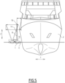
- these rolling movements cause a rocking movement of the mast 14 which alternately approaches and separates the second end 18 of the mast 14 from the naval vessel 2 when the marine craft 1 is brought into the vicinity of the naval vessel so that the body 4 extends substantially parallel to the hull of the naval vessel 2 so that it can be grasped by an operator 10 on the naval vessel 2.
- a rocking movement of the mast 14 in the absence of a stabilizing device 20 is shown in dotted lines on the Fig. 5 and must be taken into account during the recovery operation of marine craft 1 in order to avoid any collision between mast 14 and naval vessel 2.
- the marine craft 1 must be kept at a certain distance from the naval vessel 2 to take into account this rocking movement, which complicates the grasping of the gripping element by an operator 10.
- the stabilizing device 20 is arranged between the body 4 of the marine craft 1 and the mast 14 and comprises at least two parts movable relative to each other, one being mounted on the body 4 of the marine craft 1 and accompanying the rolling movements thereof and the other receiving the first end 16 of the mast 14 and compensating for the movements of the other part to maintain the elevation direction Z of the mast 14 in a substantially vertical direction, as shown in the Fig. 4 , in which the body 4 is in an inclined position relative to its normal position while the elevation direction Z of the mast 14 is maintained in a substantially vertical direction by the stabilizing device.
- the stabilizing device 20 is arranged between the body 4 of the marine craft 1 and the mast 14 and comprises at least two parts movable relative to each other, one being mounted on the body 4 of the marine craft 1 and accompanying the rolling movements thereof and the other receiving the first end 16 of the mast 14 and compensating for the movements of the other part to maintain the elevation direction Z of the mast 14 in a substantially vertical direction, as shown in the Fig. 4 , in which the body 4 is in an
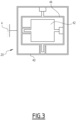
- the stabilization device 20 comprises a base 40 secured to the body 4 and at least one support 42 movable relative to the base 40 and receiving the first end 16 of the mast 14.
- the base 40 is arranged to move with the body 4 to accompany the rolling movement thereof, while the support 42 remains substantially fixed to maintain the elevation direction Z of the mast 14 in a substantially vertical direction.
- the stabilization device 20 is formed by a Stewart platform with rotary motors or linear actuators.
- the stabilization device 20 thus makes it possible to maintain the distance between the operator 10 on a deck 12 of the naval vessel 2 and the gripping element(s) 30. of the marine craft 1 in a transverse direction T perpendicular to the longitudinal direction L and to the elevation direction Z, as shown in solid lines on the Fig. 5 , which facilitates the operation of grasping a gripping element 30 by the operator 10, for example by means of a boat hook 32. Furthermore, since the mast 14 is stabilized in a substantially vertical direction, the marine craft 1 can be brought closer to the naval vessel 1 in the transverse direction T without risk of interference between the mast 14 and the naval vessel 2 due to the rolling movements of the marine craft 1. This can be seen by comparing the marine craft in dotted lines and that shown in solid lines on the Fig.
- the second end 18 of the mast 14 of the marine craft 1 according to the invention can be brought to a distance of approximately 1.2 m to 1.5 m from the deck 12 of the naval vessel 2 while this distance for a marine craft 1 without a stabilization device can be up to approximately 6 m from the naval vessel 2 in the transverse direction.
- the amplitude of movement of the mast 14 due to rolling can be approximately 5 m in the transverse direction T while with the stabilization device, this amplitude is reduced to approximately 0.3 m.
- the operator 10 can therefore much more simply grasp the gripping element 30 due to this short distance and due to the absence of relative movement in the transverse direction T between the mast 14 and the naval vessel 2.
- the stabilizing device 20 is further arranged to compensate for pitching movements of the body 4, i.e. rotational movements about a transverse axis T, in order to maintain the elevation direction Z of the mast 14 while the body 4 is subjected to such pitching movements.
- This can be achieved by adding a movable part 44 between the base 40 and the support 42 to provide an additional degree of freedom to the support 42 relative to the base 40, as shown schematically in the Fig. 3 .
- a Stewart platform also makes it possible to obtain such compensation for roll and pitch movements.
- the compensation for pitch movements further facilitates the gripping element 30 by the operator 10 by making the mast 14 practically immobile in the longitudinal and transverse directions relative to the naval vessel 2.
- the mast 14 is further mounted on a device for compensating for the heave movements of the body 4 in the elevation direction Z.
- a compensation device (not shown) is arranged to maintain the absolute height of the second end 18 of the mast 14 in the elevation direction Z, by compensating for the movements of the body 4 in the elevation direction Z, for example when the marine craft 1 passes from the peak of a wave to a trough.
- This compensation device is for example arranged between the first end 16 of the mast 14 and the device for compensating for the heave movements of the body 4 in the elevation direction Z. stabilization 20 or between the stabilization device 20 and the body 4 of the marine craft 1.
- Such a compensation device further improves the gripping of the gripping element 30 by an operator 10 by substantially immobilizing the mast 14 in the elevation direction Z relative to the naval vessel 2.
- the gripping element 30 is substantially fixed in all directions relative to the naval vessel 2 and the operator 10 has less need to compensate for possible movements of this gripping element 30 by movements of his or her arm(s) holding the boat hook 32, or even by having to lean over the deck 12 of the naval vessel 2, which could be dangerous.
- the risks of impact between the second end 18 of the mast 14 and the naval vessel 2, or worse the operator 10 are greatly reduced, or even eliminated.
- the stabilization device 20 and, where appropriate, the compensation device are controlled by the control device 6 arranged to manage the movements of the stabilization device 20 and, where appropriate, of the compensation device to keep the mast 14 substantially fixed as a function of the movements of the body 4.
- the marine craft 1 comprises for example at least one sensor of the movements of the body 4, for example formed by a gyroscope or an accelerometer, the signal emitted by this sensor being transmitted to the control device 6 which controls the stabilization device 20 and the compensation device accordingly in order to maintain the elevation direction Z of the mast 14 in a substantially vertical direction.
- the movement sensor is arranged to measure at least the rolling movements of the body 4 in rotation around the longitudinal direction and controlling the stabilization device 20 to compensate for said rolling movements so as to keep the elevation direction Z of the mast 14 aligned with a substantially vertical direction.
- the stabilization device 20 is arranged to compensate for the pitching movements of the body 4 and when a compensation device is arranged to compensate for the heave movements of the body 4, the naval craft 1 comprises one or more measuring sensors accordingly.
- the mast 14 is further provided with a proximity sensor mounted on the second end 18 of the mast 14.
- This proximity sensor is arranged to detect possible interference between the mast 14 and the naval vessel 2, the control device 6 controlling the stabilization device 20 to move the mast 14 in order to avoid said interference when the proximity sensor detects said possible interference.
- This movement of the mast 14 is done in priority with respect to the instruction making it possible to maintain the elevation direction Z of the mast 14 in a substantially vertical direction Z, that is to say that the mast 14 can then be moved so as not to extend in the vertical direction in order to avoid interference between the mast 14 and the naval vessel 2.
- control device 6 again controls the stabilization device 20 so that the elevation direction Z of the mast 14 extends in a substantially vertical direction in order to allow an operator 10 to grasp the gripping element 30.
- the proximity sensor and the corresponding control of the control device 6 thus make it possible to further limit the risks of impact between the mast 14 and the naval vessel 2, or even the operator 10.
- the marine vehicle 1 described above can be recovered simply by an operator 10 on a naval vessel 2 without requiring the presence of an operator on the marine vehicle 1 or in the water in the vicinity of this marine vehicle 1.
- the invention is thus particularly suitable for an autonomous or remotely piloted marine vehicle 1.
Landscapes
- Chemical & Material Sciences (AREA)
- Engineering & Computer Science (AREA)
- Combustion & Propulsion (AREA)
- Mechanical Engineering (AREA)
- Ocean & Marine Engineering (AREA)
- Catching Or Destruction (AREA)
- Toys (AREA)
- Control Of Position, Course, Altitude, Or Attitude Of Moving Bodies (AREA)
Applications Claiming Priority (1)
| Application Number | Priority Date | Filing Date | Title |
|---|---|---|---|
| FR2313744A FR3156425B1 (fr) | 2023-12-07 | 2023-12-07 | Engin marin comprenant un dispositif de récupération à partir d'un bâtiment naval |
Publications (1)
| Publication Number | Publication Date |
|---|---|
| EP4566933A1 true EP4566933A1 (de) | 2025-06-11 |
Family
ID=91620616
Family Applications (1)
| Application Number | Title | Priority Date | Filing Date |
|---|---|---|---|
| EP24217710.3A Pending EP4566933A1 (de) | 2023-12-07 | 2024-12-05 | Wasserfahrzeug mit einer vorrichtung zur bergung aus einem wasserfahrzeug |
Country Status (2)
| Country | Link |
|---|---|
| EP (1) | EP4566933A1 (de) |
| FR (1) | FR3156425B1 (de) |
Citations (4)
| Publication number | Priority date | Publication date | Assignee | Title |
|---|---|---|---|---|
| WO2012057633A1 (en) | 2010-10-27 | 2012-05-03 | H.Henriksen Mek.Verksted As | System for launch and recovery of a vessel |
| US9233733B2 (en) * | 2013-08-02 | 2016-01-12 | Maritime Applied Physics Corporation | Mast stabilizing device |
| CN105540457A (zh) * | 2015-12-16 | 2016-05-04 | 上海大学 | 一种无人艇自动布放回收系统 |
| KR101785710B1 (ko) * | 2015-06-02 | 2017-11-15 | 한국해양과학기술원 | 소형 작업선의 진회수 장치 및 방법 |
-
2023
- 2023-12-07 FR FR2313744A patent/FR3156425B1/fr active Active
-
2024
- 2024-12-05 EP EP24217710.3A patent/EP4566933A1/de active Pending
Patent Citations (5)
| Publication number | Priority date | Publication date | Assignee | Title |
|---|---|---|---|---|
| WO2012057633A1 (en) | 2010-10-27 | 2012-05-03 | H.Henriksen Mek.Verksted As | System for launch and recovery of a vessel |
| US20130220205A1 (en) * | 2010-10-27 | 2013-08-29 | H. Henriksen Mek. Verksted AS | System for launch and recovery of a vessel |
| US9233733B2 (en) * | 2013-08-02 | 2016-01-12 | Maritime Applied Physics Corporation | Mast stabilizing device |
| KR101785710B1 (ko) * | 2015-06-02 | 2017-11-15 | 한국해양과학기술원 | 소형 작업선의 진회수 장치 및 방법 |
| CN105540457A (zh) * | 2015-12-16 | 2016-05-04 | 上海大学 | 一种无人艇自动布放回收系统 |
Also Published As
| Publication number | Publication date |
|---|---|
| FR3156425A1 (fr) | 2025-06-13 |
| FR3156425B1 (fr) | 2025-12-12 |
Similar Documents
| Publication | Publication Date | Title |
|---|---|---|
| EP2964515B1 (de) | System und verfahren zur wiederherstellung eines autonomen unterwasserfahrzeugs | |
| CA2784188C (fr) | Engin marin ou sous-marin et procede d'arrimage associe | |
| EP2855252B1 (de) | System zum starten und zurückholen von unterwasserfahrzeugen, insbesondere gezogenen unterwasserfahrzeugen | |
| EP3956211B1 (de) | System zur rückgewinnung eines unterwasserfahrzeuges von einem schiff | |
| EP3209546B1 (de) | System zum aussetzen und bergen von see- und unterseevorrichtungen mit unterstützung durch kippbare schutzkomponenten | |
| FR3011220A1 (fr) | Stabilisateur pour bateau de plaisance au mouillage | |
| EP3464053B1 (de) | Anhängevorrichtung | |
| WO1997015490A1 (fr) | Navire tracte par cerf-volant via un bras articule | |
| EP0290325B1 (de) | System zur Erforschung und Überwachung des Meeresbodens mit einem Unterwasserfahrzeug und zu dessen Steuerung | |
| EP4566933A1 (de) | Wasserfahrzeug mit einer vorrichtung zur bergung aus einem wasserfahrzeug | |
| WO2023217817A1 (fr) | Drone marin pouvant évoluer en surface, subsurface et profondeur, et procédé associé | |
| FR3076279A1 (fr) | Engin sous-marin | |
| EP2322420B1 (de) | Oberflächenwasserfahrzeug mit schwenkbarem Tragarm.für Instrumente. | |
| EP4631845A1 (de) | Schiff mit schwimmender struktur zum starten und rückholen eines wasserfahrzeugs | |
| EP4493456B1 (de) | Geschlepptes unterwasserfahrzeug und system zur bergung solch eines unterwasserfahrzeugs | |
| WO1991007310A1 (fr) | Treuil pour remorquage d'objets immerges | |
| FR3127469A1 (fr) | Dispositif de retenue d’un cerf-volant. | |
| FR2549801A1 (fr) | Dispositif de mise a l'eau des embarcations de sauvetage prevues a bord des navires et engins flottants ou non | |
| FR3161194A1 (fr) | Dispositf de remorquage d'un engin marin par un bâtiment naval | |
| FR3131264A1 (fr) | Systeme pour la manoeuvre d un engin marin | |
| FR3113646A3 (fr) | Cerf-volant de traction | |
| FR3095637A1 (fr) | Engin marin | |
| FR2885348A1 (fr) | Gouvernail modulable pour embarcations navales a voiles | |
| FR2867449A1 (fr) | Appendice anti-derive basculant et relevable pour embarcations navales |
Legal Events
| Date | Code | Title | Description |
|---|---|---|---|
| PUAI | Public reference made under article 153(3) epc to a published international application that has entered the european phase |
Free format text: ORIGINAL CODE: 0009012 |
|
| STAA | Information on the status of an ep patent application or granted ep patent |
Free format text: STATUS: THE APPLICATION HAS BEEN PUBLISHED |
|
| AK | Designated contracting states |
Kind code of ref document: A1 Designated state(s): AL AT BE BG CH CY CZ DE DK EE ES FI FR GB GR HR HU IE IS IT LI LT LU LV MC ME MK MT NL NO PL PT RO RS SE SI SK SM TR |
|
| STAA | Information on the status of an ep patent application or granted ep patent |
Free format text: STATUS: REQUEST FOR EXAMINATION WAS MADE |
|
| 17P | Request for examination filed |
Effective date: 20251117 |
|
| GRAP | Despatch of communication of intention to grant a patent |
Free format text: ORIGINAL CODE: EPIDOSNIGR1 |
|
| STAA | Information on the status of an ep patent application or granted ep patent |
Free format text: STATUS: GRANT OF PATENT IS INTENDED |