EP4566858A1 - Convertible motor vehicle and method for controlling a foldable roof of a convertible motor vehicle - Google Patents
Convertible motor vehicle and method for controlling a foldable roof of a convertible motor vehicle Download PDFInfo
- Publication number
- EP4566858A1 EP4566858A1 EP24217037.1A EP24217037A EP4566858A1 EP 4566858 A1 EP4566858 A1 EP 4566858A1 EP 24217037 A EP24217037 A EP 24217037A EP 4566858 A1 EP4566858 A1 EP 4566858A1
- Authority
- EP
- European Patent Office
- Prior art keywords
- motor vehicle
- foldable roof
- control unit
- electronic control
- cabin
- Prior art date
- Legal status (The legal status is an assumption and is not a legal conclusion. Google has not performed a legal analysis and makes no representation as to the accuracy of the status listed.)
- Pending
Links
Images
Classifications
-
- B—PERFORMING OPERATIONS; TRANSPORTING
- B60—VEHICLES IN GENERAL
- B60J—WINDOWS, WINDSCREENS, NON-FIXED ROOFS, DOORS, OR SIMILAR DEVICES FOR VEHICLES; REMOVABLE EXTERNAL PROTECTIVE COVERINGS SPECIALLY ADAPTED FOR VEHICLES
- B60J7/00—Non-fixed roofs; Roofs with movable panels, e.g. rotary sunroofs
- B60J7/20—Vehicle storage compartments for roof parts or for collapsible flexible tops
-
- B—PERFORMING OPERATIONS; TRANSPORTING
- B60—VEHICLES IN GENERAL
- B60J—WINDOWS, WINDSCREENS, NON-FIXED ROOFS, DOORS, OR SIMILAR DEVICES FOR VEHICLES; REMOVABLE EXTERNAL PROTECTIVE COVERINGS SPECIALLY ADAPTED FOR VEHICLES
- B60J7/00—Non-fixed roofs; Roofs with movable panels, e.g. rotary sunroofs
- B60J7/08—Non-fixed roofs; Roofs with movable panels, e.g. rotary sunroofs of non-sliding type, i.e. movable or removable roofs or panels, e.g. let-down tops or roofs capable of being easily detached or of assuming a collapsed or inoperative position
- B60J7/12—Non-fixed roofs; Roofs with movable panels, e.g. rotary sunroofs of non-sliding type, i.e. movable or removable roofs or panels, e.g. let-down tops or roofs capable of being easily detached or of assuming a collapsed or inoperative position foldable; Tensioning mechanisms therefor, e.g. struts
- B60J7/1204—Control devices, e.g. for compensating tolerances, for defining movement or end position of top, for tensioning the top or for switching to an emergency mode
-
- B—PERFORMING OPERATIONS; TRANSPORTING
- B60—VEHICLES IN GENERAL
- B60J—WINDOWS, WINDSCREENS, NON-FIXED ROOFS, DOORS, OR SIMILAR DEVICES FOR VEHICLES; REMOVABLE EXTERNAL PROTECTIVE COVERINGS SPECIALLY ADAPTED FOR VEHICLES
- B60J7/00—Non-fixed roofs; Roofs with movable panels, e.g. rotary sunroofs
- B60J7/02—Non-fixed roofs; Roofs with movable panels, e.g. rotary sunroofs of sliding type, e.g. comprising guide shoes
- B60J7/04—Non-fixed roofs; Roofs with movable panels, e.g. rotary sunroofs of sliding type, e.g. comprising guide shoes with rigid plate-like element or elements, e.g. open roofs with harmonica-type folding rigid panels
- B60J7/057—Driving or actuating arrangements e.g. manually operated levers or knobs
- B60J7/0573—Driving or actuating arrangements e.g. manually operated levers or knobs power driven arrangements, e.g. electrical
-
- B—PERFORMING OPERATIONS; TRANSPORTING
- B60—VEHICLES IN GENERAL
- B60J—WINDOWS, WINDSCREENS, NON-FIXED ROOFS, DOORS, OR SIMILAR DEVICES FOR VEHICLES; REMOVABLE EXTERNAL PROTECTIVE COVERINGS SPECIALLY ADAPTED FOR VEHICLES
- B60J7/00—Non-fixed roofs; Roofs with movable panels, e.g. rotary sunroofs
- B60J7/08—Non-fixed roofs; Roofs with movable panels, e.g. rotary sunroofs of non-sliding type, i.e. movable or removable roofs or panels, e.g. let-down tops or roofs capable of being easily detached or of assuming a collapsed or inoperative position
- B60J7/12—Non-fixed roofs; Roofs with movable panels, e.g. rotary sunroofs of non-sliding type, i.e. movable or removable roofs or panels, e.g. let-down tops or roofs capable of being easily detached or of assuming a collapsed or inoperative position foldable; Tensioning mechanisms therefor, e.g. struts
- B60J7/14—Non-fixed roofs; Roofs with movable panels, e.g. rotary sunroofs of non-sliding type, i.e. movable or removable roofs or panels, e.g. let-down tops or roofs capable of being easily detached or of assuming a collapsed or inoperative position foldable; Tensioning mechanisms therefor, e.g. struts with a plurality of rigid plate-like elements or rigid non plate-like elements, e.g. with non-slidable, but pivotable or foldable movement
- B60J7/143—Non-fixed roofs; Roofs with movable panels, e.g. rotary sunroofs of non-sliding type, i.e. movable or removable roofs or panels, e.g. let-down tops or roofs capable of being easily detached or of assuming a collapsed or inoperative position foldable; Tensioning mechanisms therefor, e.g. struts with a plurality of rigid plate-like elements or rigid non plate-like elements, e.g. with non-slidable, but pivotable or foldable movement for covering the passenger compartment
- B60J7/145—Non-fixed roofs; Roofs with movable panels, e.g. rotary sunroofs of non-sliding type, i.e. movable or removable roofs or panels, e.g. let-down tops or roofs capable of being easily detached or of assuming a collapsed or inoperative position foldable; Tensioning mechanisms therefor, e.g. struts with a plurality of rigid plate-like elements or rigid non plate-like elements, e.g. with non-slidable, but pivotable or foldable movement for covering the passenger compartment at least two elements being folded in clamp-shell fashion
-
- G—PHYSICS
- G07—CHECKING-DEVICES
- G07C—TIME OR ATTENDANCE REGISTERS; REGISTERING OR INDICATING THE WORKING OF MACHINES; GENERATING RANDOM NUMBERS; VOTING OR LOTTERY APPARATUS; ARRANGEMENTS, SYSTEMS OR APPARATUS FOR CHECKING NOT PROVIDED FOR ELSEWHERE
- G07C5/00—Registering or indicating the working of vehicles
- G07C5/08—Registering or indicating performance data other than driving, working, idle, or waiting time, with or without registering driving, working, idle or waiting time
- G07C5/0816—Indicating performance data, e.g. occurrence of a malfunction
- G07C5/0825—Indicating performance data, e.g. occurrence of a malfunction using optical means
-
- G—PHYSICS
- G07—CHECKING-DEVICES
- G07C—TIME OR ATTENDANCE REGISTERS; REGISTERING OR INDICATING THE WORKING OF MACHINES; GENERATING RANDOM NUMBERS; VOTING OR LOTTERY APPARATUS; ARRANGEMENTS, SYSTEMS OR APPARATUS FOR CHECKING NOT PROVIDED FOR ELSEWHERE
- G07C5/00—Registering or indicating the working of vehicles
- G07C5/08—Registering or indicating performance data other than driving, working, idle, or waiting time, with or without registering driving, working, idle or waiting time
- G07C5/0816—Indicating performance data, e.g. occurrence of a malfunction
- G07C5/0833—Indicating performance data, e.g. occurrence of a malfunction using audio means
-
- B—PERFORMING OPERATIONS; TRANSPORTING
- B60—VEHICLES IN GENERAL
- B60J—WINDOWS, WINDSCREENS, NON-FIXED ROOFS, DOORS, OR SIMILAR DEVICES FOR VEHICLES; REMOVABLE EXTERNAL PROTECTIVE COVERINGS SPECIALLY ADAPTED FOR VEHICLES
- B60J7/00—Non-fixed roofs; Roofs with movable panels, e.g. rotary sunroofs
- B60J7/08—Non-fixed roofs; Roofs with movable panels, e.g. rotary sunroofs of non-sliding type, i.e. movable or removable roofs or panels, e.g. let-down tops or roofs capable of being easily detached or of assuming a collapsed or inoperative position
- B60J7/12—Non-fixed roofs; Roofs with movable panels, e.g. rotary sunroofs of non-sliding type, i.e. movable or removable roofs or panels, e.g. let-down tops or roofs capable of being easily detached or of assuming a collapsed or inoperative position foldable; Tensioning mechanisms therefor, e.g. struts
- B60J7/14—Non-fixed roofs; Roofs with movable panels, e.g. rotary sunroofs of non-sliding type, i.e. movable or removable roofs or panels, e.g. let-down tops or roofs capable of being easily detached or of assuming a collapsed or inoperative position foldable; Tensioning mechanisms therefor, e.g. struts with a plurality of rigid plate-like elements or rigid non plate-like elements, e.g. with non-slidable, but pivotable or foldable movement
- B60J7/143—Non-fixed roofs; Roofs with movable panels, e.g. rotary sunroofs of non-sliding type, i.e. movable or removable roofs or panels, e.g. let-down tops or roofs capable of being easily detached or of assuming a collapsed or inoperative position foldable; Tensioning mechanisms therefor, e.g. struts with a plurality of rigid plate-like elements or rigid non plate-like elements, e.g. with non-slidable, but pivotable or foldable movement for covering the passenger compartment
Definitions
- the invention relates to a convertible motor vehicle and a method for controlling a foldable roof of a convertible motor vehicle.
- Convertible motor vehicles comprising:
- Such convertible motor vehicles further comprise:
- An object of the invention is to satisfy the need set forth above, preferably in a simple and cost-effective manner.
- the object is achieved by a motor vehicle as defined in claim 1.
- the object is also achieved by a control method as defined in claim 6.
- the dependent claims define particular embodiments of the invention.
- reference numeral 1 is used to indicate, as a whole, a convertible motor vehicle.
- the motor vehicle 1 is a cabriolet or spider car, for example of sports type.
- the motor vehicle 1 comprises a frame 2 defining a cabin 3 adapted to accommodate at least a driver and possibly one or more passengers and a plurality of wheels - not illustrated - rotatable relative to the frame 2 about respective rotational axes.
- the motor vehicle 1 further defines a longitudinal direction X, a direction Z, which is orthogonal to the longitudinal direction X and is vertically directed to the ground on which the wheels rest, and a direction Y which is orthogonal to the longitudinal direction X and to the direction Z.
- the motor vehicle 1 also comprises a front portion 1a and a rear portion 1b relative to a forward direction A.
- the forward direction A is oriented in the sense directed from the rear portion 1b to the front portion 1a ( Figure 1 ).
- the cabin 3 comprises a top 3a on the side opposite the wheels along the direction Z.
- the top 3a defines an opening 3b through which the cabin 3 fluidly communicates with the outside of the motor vehicle 1 ( Figures 4 and 5 ).
- the motor vehicle 1 further comprises:
- the foldable roof 6 is movable between an opening position, in which it is housed folded inside the stowage compartment 7 and the cabin 3 is fluidly communicating with the outside of the motor vehicle 1 ( Figure 5 ), and a closing position, in which the foldable roof 6 extends outside the stowage compartment 7 and covers the cabin 3 ( Figure 2 ).
- the roof 6 comprises a cover 11, for example made of a deformable fabric.
- the cover 11 obstructs the opening 3b and delimits the cabin 3 at the top ( Figures 1 and 2 ).
- the stowage compartment 7 is interposed between the cabin 3 and the rear portion 1b.
- the motor vehicle 1 also comprises a lid 8 coupled in a movable manner to the frame 2 and adapted to selectively close the stowage compartment 7.
- the lid 8 is adapted to move between a closing position ( Figures 2 and 5 ) and an opening position ( Figures 3 and 4 ) of the stowage compartment 7.
- the motor vehicle 1 does not comprise the lid 8 and the stowage compartment 7 is constantly fluidly communicating with the outside of the motor vehicle 1.
- the motor vehicle 1 further comprises a front windscreen 4 on the side of the front portion 1a and a rear window 5 on the side of the rear portion 1b.
- the front windscreen 4 and the rear window 5 are integral with the frame 2.
- the cabin 3 is delimited at the front by the front windscreen 4 and at the back by the rear window 5.
- the motor vehicle 1 comprises the front windscreen 4 and the rear window 5 is integrated in the foldable roof 6 and is therefore movable relative to the frame 2.
- the motor vehicle 1 further comprises a luggage compartment 9 arranged at the rear portion 1b.
- the stowage compartment 7 and the luggage compartment 9 communicate with each other.
- the motor vehicle 1 further comprises ( Figure 6 ):
- the sensory system 50 comprises one or more humidity sensors.
- such humidity sensors are arranged inside the stowage compartment 7.
- the quantity u is, for example, the relative humidity or the absolute humidity or the specific humidity inside the stowage compartment 7.
- the motor vehicle 1 also comprises a drive unit 12 adapted to automatically move the foldable roof 6 between the opening position and the closing position and operatively connected to the electronic control unit 70 ( Figure 6 ).
- the drive unit 12 is known per se and is not described in detail in the following.
- the drive unit 12 comprises an electric drive or a hydraulic drive.
- the control unit 70 is programmed to command the sensory system 50 to detect the quantity u after a given time interval from the moment in which the drive unit 12 has moved the foldable roof 6 from the closing position to the opening position. This causes the possible humidity released from the wet or humid foldable roof 6 inside the stowage compartment 7 to be sufficient for being detectable by the sensory system 50.
- the time interval is equal to 30 seconds, or is greater than 30 seconds.
- the electronic control unit 70 is programmed to command the sensory system 50 to detect the quantity u as soon as the foldable roof 6 has reached the opening position.
- control unit 70 is programmed to command the sensory system 50 to periodically detect the quantity u when the foldable roof 6 is in the opening position.
- control unit 70 is programmed to command the detection of the quantity u at intervals of 30 seconds.
- the electronic control unit 70 is programmed to store a predetermined threshold value u ⁇ , for example in a step of designing or calibrating the motor vehicle 1.
- the control unit 70 is programmed to command the sensory system 50 to detect and/or determine the threshold value u ⁇ .
- the threshold value u ⁇ is the value of the quantity u when said foldable roof 6 is in the closing position or is moved from the closing position towards the opening position.
- the detected quantity u is compared with a threshold value u ⁇ determined each time the foldable roof 6 is moved towards the opening position and associated with the humidity existing in the stowage compartment 7 before placing the foldable roof 6 back in the stowage compartment 7.
- control unit 70 is programmed to command the sensory system 50 to detect and/or determine the threshold value u ⁇ at the same instant in which the control unit 70 commands the drive unit 12 to move the foldable roof 6 from the closing position to the opening position.
- the signalling means 60 comprise at least one of an indicator light 61, a sound emitter 62, a control panel 63 and a transceiver 64 ( Figure 6 ).
- the indicator light 61 is adapted to emit a light signal for signalling to a user of the motor vehicle 1 the risk of damage to the foldable roof 6.
- the indicator light 61 is arranged in the cabin 3 and/or is visible from the cabin 3.
- the sound emitter 62 is adapted to emit a sound signal for signalling to a user of the motor vehicle 1 the risk of damage to the foldable roof 6, for example, so that such sound signal is audible inside the cabin 3.
- the control panel 63 is for example an infotainment system arranged in the cabin 3.
- the transceiver 64 is adapted to be remotely operatively connected to a mobile device 65, for example, a smartphone or a tablet.
- a mobile device 65 for example, a smartphone or a tablet.
- the transceiver 64 is adapted to send a signal to said mobile device 65 for signalling to a user of the mobile device 65 the risk of damage to the foldable roof 6.
- a user of the motor vehicle 1 commands the automatic movement of the foldable roof 6 between the opening position and the closing position by means of the drive unit 12.
- the sensory system 50 detects the value of the quantity u inside the stowage compartment 7 and the control unit 70 compares such detected value of the quantity u with the threshold value u ⁇ . If the detected quantity u is greater than the threshold value u ⁇ , it is likely that the foldable roof 6 is humid or wet. Consequently, the control unit 70 commands the signalling means 60 to signal the potential risk of damage to the foldable roof 6. In this manner, the user of the motor vehicle 1 is induced to move the foldable roof 6 to the closing position or to command the movement of the foldable roof 6 to the closing position by means of the drive unit 12, allowing its correct drying outside the stowage compartment 7.
- the sensory system 50 detects the quantity u after a given time interval from the conclusion of the movement of the foldable roof 6 to the opening position. Alternatively or additionally, the sensory system 50 periodically detects the value of the quantity u in the stowage compartment 7 when the foldable roof 6 is in the opening position.
- the threshold value u ⁇ is predetermined ab initio and stored in the electronic control unit 70, or is detected and/or determined in real time by the sensory system 50 at each movement of the foldable roof 6 towards the opening position.
- the control unit 70 commands the sensory system 50 to detect the value of the quantity u when the foldable roof 6 is in the closing position or is moved from the closing position towards the opening position (for example, following a command of a user of the motor vehicle 1) and utilises such detected value as threshold value u ⁇ for the following comparison.
- the electronic control unit 70 is programmed to compare the quantity u detected by the sensory system 50 with the threshold value u ⁇ and to command the signalling means 60 to signal the risk of damage to the foldable roof 6 when the detected quantity u is greater than the threshold value u ⁇ , the risk of the formation of the permanent folds in the foldable roof 6 is significantly reduced.
- the user of the motor vehicle 1, once informed of the risk will be induced to command the movement of the foldable roof 6 to the closing position, allowing a correct drying thereof outside the stowage compartment 7.
- control unit 70 is programmed to command the sensory system 50 to periodically detect the quantity u when the foldable roof 6 is in the opening position, it is possible to control with a high level of reliability the presence of humidity or an increase in the same in the stowage compartment 7.
- the detected quantity u is compared with a threshold value u ⁇ determined each time and associated with the humidity existing in the stowage compartment 7 before the placing of the foldable roof 6 back in the stowage compartment 7, the possible formation of humidity in the stowage compartment 7 is determined based on a threshold value updated over time, which can also keep into account atmospheric humidity variations outside the motor vehicle 1.
Landscapes
- Engineering & Computer Science (AREA)
- Mechanical Engineering (AREA)
- Physics & Mathematics (AREA)
- General Physics & Mathematics (AREA)
- Multimedia (AREA)
- Power-Operated Mechanisms For Wings (AREA)
Abstract
Description
- This patent application claims priority from
Italian patent application no. 102023000025968 filed on December 5, 2023 - The invention relates to a convertible motor vehicle and a method for controlling a foldable roof of a convertible motor vehicle.
- Convertible motor vehicles are known comprising:
- a frame defining a cabin adapted to accommodate the driver and possible passengers;
- a plurality of wheels rotatable relative to the frame; and
- a stowage compartment obtained at the back of the cabin along a forward direction of the motor vehicle.
- Such convertible motor vehicles further comprise:
- a roof movable relative to the frame and adapted to selectively cover the cabin at a top thereof opposite to the wheels along a vertical direction of the motor vehicle; and
- a drive unit adapted to move the roof between an opening position, in which the roof is housed folded inside the stowage compartment and the cabin is uncovered and fluidly communicating with the outside of the motor vehicle, and a closing position, in which the roof extends outside the stowage compartment and covers the cabin.
- In such convertible motor vehicles, it has been observed that arranging the folded roof in wet or humid conditions - for example, following the fall of rain or the washing of the motor vehicle - inside the stowage compartment, there is a risk of permanently damaging the foldable material of the roof. Specifically, if the roof is put back wet in the stowage compartment to its complete drying, the folds due to the folding of the roof tend to be imprinted in the foldable material, remaining visible also when the roof is extended outside the stowage compartment. This phenomenon is known in the field as "ironing effect".
- The visible folds of the roof not only invalidate the quality of the roof from the aesthetic point of view, but are also relevant from the structural point of view, since they determine a permanent alteration of the elastic characteristics of the foldable material, significantly reducing the useful life of the roof.
- In light of the above, the need is felt to reduce the risk of the formation of permanent folds in the movable roof of the convertible motor vehicles.
- An object of the invention is to satisfy the need set forth above, preferably in a simple and cost-effective manner.
- The object is achieved by a motor vehicle as defined in claim 1. The object is also achieved by a control method as defined in
claim 6. The dependent claims define particular embodiments of the invention. - In the following, an embodiment of the invention is described for a better understanding thereof, by way of nonlimiting example and with reference to the accompanying drawings, wherein:
-
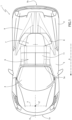
Figure 1 is a schematic top representation of a motor vehicle according to the present invention with parts removed for clarity; -
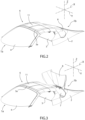
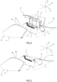
Figures 2 to 5 are schematic perspective views, with parts removed for clarity, of a portion of the motor vehicle ofFigure 1 in four respective different operating positions; and -
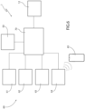
Figure 6 is a schematic view of a portion of the motor vehicle ofFigures 1 to 5 . - In
Figure 1 , reference numeral 1 is used to indicate, as a whole, a convertible motor vehicle. Preferably and without this involving any loss of generality, the motor vehicle 1 is a cabriolet or spider car, for example of sports type. - The motor vehicle 1 comprises a
frame 2 defining acabin 3 adapted to accommodate at least a driver and possibly one or more passengers and a plurality of wheels - not illustrated - rotatable relative to theframe 2 about respective rotational axes. - The motor vehicle 1 further defines a longitudinal direction X, a direction Z, which is orthogonal to the longitudinal direction X and is vertically directed to the ground on which the wheels rest, and a direction Y which is orthogonal to the longitudinal direction X and to the direction Z.
- The motor vehicle 1 also comprises a
front portion 1a and arear portion 1b relative to a forward direction A. In detail, the forward direction A is oriented in the sense directed from therear portion 1b to thefront portion 1a (Figure 1 ). - The
cabin 3 comprises atop 3a on the side opposite the wheels along the direction Z. The top 3a defines an opening 3b through which thecabin 3 fluidly communicates with the outside of the motor vehicle 1 (Figures 4 and 5 ). - The motor vehicle 1 further comprises:
- a
foldable roof 6 movable relative to theframe 2 and adapted to selectively cover thecabin 3 at thetop 3a; and - a
stowage compartment 7 adapted to contain thefoldable roof 6 in at least some operating positions thereof. - As is illustrated in
Figures 2 to 5 , thefoldable roof 6 is movable between an opening position, in which it is housed folded inside thestowage compartment 7 and thecabin 3 is fluidly communicating with the outside of the motor vehicle 1 (Figure 5 ), and a closing position, in which thefoldable roof 6 extends outside thestowage compartment 7 and covers the cabin 3 (Figure 2 ). In detail, theroof 6 comprises acover 11, for example made of a deformable fabric. In further detail, when thefoldable roof 6 is in the closing position, thecover 11 obstructs the opening 3b and delimits thecabin 3 at the top (Figures 1 and2 ). - The
stowage compartment 7 is interposed between thecabin 3 and therear portion 1b. - In the shown embodiment, the motor vehicle 1 also comprises a
lid 8 coupled in a movable manner to theframe 2 and adapted to selectively close thestowage compartment 7. In detail, thelid 8 is adapted to move between a closing position (Figures 2 and5 ) and an opening position (Figures 3 and4 ) of thestowage compartment 7. According to an embodiment not illustrated, the motor vehicle 1 does not comprise thelid 8 and thestowage compartment 7 is constantly fluidly communicating with the outside of the motor vehicle 1. - In the shown embodiment, the motor vehicle 1 further comprises a
front windscreen 4 on the side of thefront portion 1a and arear window 5 on the side of therear portion 1b. In detail, thefront windscreen 4 and therear window 5 are integral with theframe 2. Furthermore, thecabin 3 is delimited at the front by thefront windscreen 4 and at the back by therear window 5. - According to an embodiment not illustrated, the motor vehicle 1 comprises the
front windscreen 4 and therear window 5 is integrated in thefoldable roof 6 and is therefore movable relative to theframe 2. - The motor vehicle 1 further comprises a
luggage compartment 9 arranged at therear portion 1b. Preferably, thestowage compartment 7 and theluggage compartment 9 communicate with each other. - Advantageously, the motor vehicle 1 further comprises (
Figure 6 ): - a
sensory system 50 adapted to detect a quantity u associated with the humidity of the air inside thestowage compartment 7; - signalling means 60 adapted to signal a potential risk of damage to the
foldable roof 6; and - an
electronic control unit 70 operatively connected to thesensory system 50 and the signalling means 60; - In detail, the
sensory system 50 comprises one or more humidity sensors. In further detail, such humidity sensors are arranged inside thestowage compartment 7. - The quantity u is, for example, the relative humidity or the absolute humidity or the specific humidity inside the
stowage compartment 7. - The motor vehicle 1 also comprises a
drive unit 12 adapted to automatically move thefoldable roof 6 between the opening position and the closing position and operatively connected to the electronic control unit 70 (Figure 6 ). - The
drive unit 12 is known per se and is not described in detail in the following. By way of example, thedrive unit 12 comprises an electric drive or a hydraulic drive. - The
control unit 70 is programmed to command thesensory system 50 to detect the quantity u after a given time interval from the moment in which thedrive unit 12 has moved thefoldable roof 6 from the closing position to the opening position. This causes the possible humidity released from the wet or humidfoldable roof 6 inside thestowage compartment 7 to be sufficient for being detectable by thesensory system 50. - For example, the time interval is equal to 30 seconds, or is greater than 30 seconds. Alternatively, the
electronic control unit 70 is programmed to command thesensory system 50 to detect the quantity u as soon as thefoldable roof 6 has reached the opening position. - Alternatively or additionally, the
control unit 70 is programmed to command thesensory system 50 to periodically detect the quantity u when thefoldable roof 6 is in the opening position. For example, thecontrol unit 70 is programmed to command the detection of the quantity u at intervals of 30 seconds. - According to an embodiment of the present invention, the
electronic control unit 70 is programmed to store a predetermined threshold value uθ, for example in a step of designing or calibrating the motor vehicle 1. - According to an alternative embodiment of the present invention, the
control unit 70 is programmed to command thesensory system 50 to detect and/or determine the threshold value uθ. In particular, the threshold value uθ is the value of the quantity u when saidfoldable roof 6 is in the closing position or is moved from the closing position towards the opening position. In other words, according to such alternative embodiment, the detected quantity u is compared with a threshold value uθ determined each time thefoldable roof 6 is moved towards the opening position and associated with the humidity existing in thestowage compartment 7 before placing thefoldable roof 6 back in thestowage compartment 7. - Preferably, the
control unit 70 is programmed to command thesensory system 50 to detect and/or determine the threshold value uθ at the same instant in which thecontrol unit 70 commands thedrive unit 12 to move thefoldable roof 6 from the closing position to the opening position. - The signalling means 60 comprise at least one of an
indicator light 61, asound emitter 62, acontrol panel 63 and a transceiver 64 (Figure 6 ). - In detail, the
indicator light 61 is adapted to emit a light signal for signalling to a user of the motor vehicle 1 the risk of damage to thefoldable roof 6. For example, theindicator light 61 is arranged in thecabin 3 and/or is visible from thecabin 3. - The
sound emitter 62 is adapted to emit a sound signal for signalling to a user of the motor vehicle 1 the risk of damage to thefoldable roof 6, for example, so that such sound signal is audible inside thecabin 3. - The
control panel 63 is for example an infotainment system arranged in thecabin 3. - The
transceiver 64 is adapted to be remotely operatively connected to amobile device 65, for example, a smartphone or a tablet. In detail, thetransceiver 64 is adapted to send a signal to saidmobile device 65 for signalling to a user of themobile device 65 the risk of damage to thefoldable roof 6. - In the following, the operation of the motor vehicle 1 is described.
- In use, a user of the motor vehicle 1 commands the automatic movement of the
foldable roof 6 between the opening position and the closing position by means of thedrive unit 12. - During the operation, the
sensory system 50 detects the value of the quantity u inside thestowage compartment 7 and thecontrol unit 70 compares such detected value of the quantity u with the threshold value uθ. If the detected quantity u is greater than the threshold value uθ, it is likely that thefoldable roof 6 is humid or wet. Consequently, thecontrol unit 70 commands the signalling means 60 to signal the potential risk of damage to thefoldable roof 6. In this manner, the user of the motor vehicle 1 is induced to move thefoldable roof 6 to the closing position or to command the movement of thefoldable roof 6 to the closing position by means of thedrive unit 12, allowing its correct drying outside thestowage compartment 7. - In detail, the
sensory system 50 detects the quantity u after a given time interval from the conclusion of the movement of thefoldable roof 6 to the opening position. Alternatively or additionally, thesensory system 50 periodically detects the value of the quantity u in thestowage compartment 7 when thefoldable roof 6 is in the opening position. - Additionally, the threshold value uθ is predetermined ab initio and stored in the
electronic control unit 70, or is detected and/or determined in real time by thesensory system 50 at each movement of thefoldable roof 6 towards the opening position. In detail, thecontrol unit 70 commands thesensory system 50 to detect the value of the quantity u when thefoldable roof 6 is in the closing position or is moved from the closing position towards the opening position (for example, following a command of a user of the motor vehicle 1) and utilises such detected value as threshold value uθ for the following comparison. - Based on the foregoing, the advantages of the motor vehicle 1 and of the control method according to the invention are evident.
- In particular, since the
electronic control unit 70 is programmed to compare the quantity u detected by thesensory system 50 with the threshold value uθ and to command the signalling means 60 to signal the risk of damage to thefoldable roof 6 when the detected quantity u is greater than the threshold value uθ, the risk of the formation of the permanent folds in thefoldable roof 6 is significantly reduced. In fact, the user of the motor vehicle 1, once informed of the risk, will be induced to command the movement of thefoldable roof 6 to the closing position, allowing a correct drying thereof outside thestowage compartment 7. - Since the detection of the quantity u occurs after a given time interval from the moment in which the
drive unit 12 has moved thefoldable roof 6 from the closing position to the opening position, it is possible to improve the efficiency with which the possible humidity formed inside thestowage compartment 7 can be detected. - Since the
control unit 70 is programmed to command thesensory system 50 to periodically detect the quantity u when thefoldable roof 6 is in the opening position, it is possible to control with a high level of reliability the presence of humidity or an increase in the same in thestowage compartment 7. - Since the detected quantity u is compared with a threshold value uθ determined each time and associated with the humidity existing in the
stowage compartment 7 before the placing of thefoldable roof 6 back in thestowage compartment 7, the possible formation of humidity in thestowage compartment 7 is determined based on a threshold value updated over time, which can also keep into account atmospheric humidity variations outside the motor vehicle 1. - Finally, it is clear that modifications and variations can be made to the motor vehicle 1 and to the control method according to the invention, which do not anyway depart from the scope of protection defined by the claims.
Claims (9)
- Motor vehicle (1) comprising:- a frame (2) defining a cabin (3) adapted to accommodate at least a driver of said motor vehicle;- a plurality of wheels rotatable relative to said frame (2) about respective rotational axes;- a foldable roof (6) movable relative to said frame (2) and adapted to selectively cover, in use, said cabin (3) at a top (3a) thereof opposite to said wheels along a direction (Z) vertical, in use; and- a stowage compartment (7) adapted to contain, in use, said foldable roof (6);said foldable roof (6) being movable between an opening position, wherein it is housed folded inside said stowage compartment (7) and said cabin (3) is fluidly communicating with the outside of said motor vehicle (1), and a closing position, wherein said foldable roof (6) extends outside said stowage compartment (7) and covers said cabin (3);characterized in that it further comprises:- a sensory system (50) adapted to detect a quantity (u) associated with the humidity of the air inside said stowage compartment (7);- signalling means (60) adapted to signal, in use, a potential risk of damage to said foldable roof (6);- an electronic control unit (70) operatively connected to said sensory system (50) and said signalling means (60);said electronic control unit (70) being configured to compare the quantity (u) detected, in use, by said sensory system (50) with a threshold value (uθ) and to command said signalling means (60) to signal said potential risk of damage to said foldable roof (6), when said quantity (u) detected, in use, is greater than said threshold value (uθ), in order for said foldable roof (6) to be moved to said closing position.
- - Motor vehicle according to claim 1, further comprising a drive unit (12) adapted to automatically move said foldable roof (6) between said opening position and said closing position;said drive unit (12) being operatively connected to said electronic control unit (70);said electronic control unit (70) being programmed to command said sensory system (50) to detect said quantity (u) after a time interval from the moment in which said drive unit (12) has moved, in use, said foldable roof (6) from said closing position to said opening position.
- - Motor vehicle according to claim 1 or 2, wherein said electronic control unit (70) is programmed to command said sensory system (50) to periodically detect said quantity (u) when said foldable roof (6) is, in use, in said opening position.
- - Motor vehicle according to any one of the foregoing claims, wherein said electronic control unit (70) is programmed to command said sensory system (50) to detect, in use, said threshold value (uθ);
said threshold value (uθ) being the value of said quantity (u) when said foldable roof (6) is, in use, in the closing position or when it is moved, in use, from said closing position towards said opening position. - - Motor vehicle according to any one of the foregoing claims, wherein said signalling means (60) comprise at least one of:- an indicator light (61);- a sound emitter (62);- a control panel (63); and- a transceiver (64) adapted to be remotely operatively connected to a mobile device (65).
- - Method of controlling a foldable roof (6) of a motor vehicle (1); said motor vehicle (1) comprising:- a frame (2) defining a cabin (3) adapted to accommodate at least a driver of said motor vehicle (1);- a plurality of wheels rotatable relative to said frame (2) about respective rotational axes;- said foldable roof (6) movable relative to said frame (3) and adapted a selectively cover, in use, said cabin (3) at a top (3a) thereof opposite to said wheels along a direction (Z) vertical, in use; and- a stowage compartment (7) adapted to contain, in use, said foldable roof (6);said foldable roof (6) being movable between an opening position, wherein it is housed folded inside said stowage compartment (7) and said cabin (3) is fluidly communicating with the outside of said motor vehicle (1), and a closing position, wherein said foldable roof (6) extends outside said stowage compartment (7) and covers said cabin (3);said method being characterized in that it comprises the steps of:i) detecting a quantity (u) associated with the humidity of the air inside said stowage compartment (7) by means of a sensory system (50) of said motor vehicle (1);ii) comparing the quantity (u) detected during said step i) by said sensory system (50) with a threshold value (uθ) by means of an electronic control unit (70) of said motor vehicle (1); said electronic control unit (70) being operatively connected to said sensory system (50); andiii) commanding signalling means (60) of said motor vehicle (1) by means of said electronic control unit (70) to signal a potential risk of damage to said foldable roof (6) when at the end of said step ii) said detected quantity (u) is greater than said threshold value (uθ), in order for said foldable roof (6) to be moved to said closing position;said electronic control unit (70) being operatively connected to said signalling means (60).
- - Method according to claim 6, wherein said step i) is commanded by said electronic control unit (70) after a time interval from the moment in which a drive unit (12) of said motor vehicle (1) has moved said foldable roof (6) from said closing position to said opening position.
- - Method according to claim 6 or 7, wherein said step i) is periodically commanded by said electronic control unit (70) while said foldable roof (6) is in said opening position.
- - Method according to any one of claims 6 to 8, comprising the further step iv) of detecting said threshold value (uθ) by means of said sensory system (50);
said threshold value (uθ) being the value of said quantity (u) when said foldable roof (6) is in the closing position or is moved from said closing position towards said opening position.
Applications Claiming Priority (1)
| Application Number | Priority Date | Filing Date | Title |
|---|---|---|---|
| IT102023000025968A IT202300025968A1 (en) | 2023-12-05 | 2023-12-05 | CONVERTIBLE MOTOR VEHICLE AND METHOD OF CHECKING A FOLDING ROOF OF A CONVERTIBLE MOTOR VEHICLE |
Publications (1)
| Publication Number | Publication Date |
|---|---|
| EP4566858A1 true EP4566858A1 (en) | 2025-06-11 |
Family
ID=90123923
Family Applications (1)
| Application Number | Title | Priority Date | Filing Date |
|---|---|---|---|
| EP24217037.1A Pending EP4566858A1 (en) | 2023-12-05 | 2024-12-03 | Convertible motor vehicle and method for controlling a foldable roof of a convertible motor vehicle |
Country Status (3)
| Country | Link |
|---|---|
| US (1) | US20250178418A1 (en) |
| EP (1) | EP4566858A1 (en) |
| IT (1) | IT202300025968A1 (en) |
Families Citing this family (1)
| Publication number | Priority date | Publication date | Assignee | Title |
|---|---|---|---|---|
| JP1821954S (en) * | 2023-04-26 | 2026-03-17 | Graphical User Interface |
Citations (2)
| Publication number | Priority date | Publication date | Assignee | Title |
|---|---|---|---|---|
| DE29814310U1 (en) * | 1998-08-10 | 1998-11-12 | Merlaku, Kastriot, 84347 Pfarrkirchen | Control unit with rain, air pressure and humidity sensors for convertibles |
| DE102015209664A1 (en) * | 2015-05-27 | 2016-12-01 | Bayerische Motoren Werke Aktiengesellschaft | Monitoring a vehicle roof |
Family Cites Families (2)
| Publication number | Priority date | Publication date | Assignee | Title |
|---|---|---|---|---|
| FR2866835B1 (en) * | 2004-07-02 | 2008-04-04 | France Design | CONTROL DEVICE FOR TILTING A MOBILE ROOF AND CORRESPONDING VEHICLE |
| US20060006701A1 (en) * | 2004-07-06 | 2006-01-12 | Jason Wells | System and method for rain detection and automatic operation of power roof and power windows |
-
2023
- 2023-12-05 IT IT102023000025968A patent/IT202300025968A1/en unknown
-
2024
- 2024-12-02 US US18/965,107 patent/US20250178418A1/en active Pending
- 2024-12-03 EP EP24217037.1A patent/EP4566858A1/en active Pending
Patent Citations (2)
| Publication number | Priority date | Publication date | Assignee | Title |
|---|---|---|---|---|
| DE29814310U1 (en) * | 1998-08-10 | 1998-11-12 | Merlaku, Kastriot, 84347 Pfarrkirchen | Control unit with rain, air pressure and humidity sensors for convertibles |
| DE102015209664A1 (en) * | 2015-05-27 | 2016-12-01 | Bayerische Motoren Werke Aktiengesellschaft | Monitoring a vehicle roof |
Also Published As
| Publication number | Publication date |
|---|---|
| IT202300025968A1 (en) | 2025-06-05 |
| US20250178418A1 (en) | 2025-06-05 |
Similar Documents
| Publication | Publication Date | Title |
|---|---|---|
| US12269330B2 (en) | Integrated vehicle cover | |
| CA2756153C (en) | Independent running board actuation | |
| US7140659B2 (en) | Protective device for a luggage area of a motor vehicle | |
| CN105313654B (en) | Vehicle anti-pinch sunroof control system and method | |
| KR101974121B1 (en) | Opening method of trunk cover for vehicle | |
| US7174985B2 (en) | Exterior airbag device | |
| US20050248184A1 (en) | Pneumatically inflatable structural element for automotive vehicles | |
| US20250178418A1 (en) | Convertible motor vehicle and method for controlling a foldable roof of a convertible motor vehicle | |
| CN105835803A (en) | Automatic mitigation of vehicle wind buffeting | |
| CN117980169A (en) | Flow guide device installed on panel components | |
| US6054821A (en) | Motor-vehicle convertible-top system, and a method for operating a motor-vehicle convertible-top system | |
| US8756863B2 (en) | Scheme for operating an electric window lifter | |
| CN109930942A (en) | Rainfall perceives vehicle window control unit, system and control method and vehicle | |
| US9150180B1 (en) | Inflatable protection mechanisms for vehicle instrument panel | |
| US20030218346A1 (en) | Cabriolet vehicle with a check device for checking a given convertible top stowage volume | |
| KR20250065571A (en) | Vehicle rain barrier system interlocked with door | |
| JP2007269102A (en) | Wind slob reduction device for vehicles | |
| US20110060502A1 (en) | Motor vehicle with a ride level control device | |
| CN109866834A (en) | Air deflector component for motor vehicles | |
| KR20130022665A (en) | The automatic umbrella system of vehicle | |
| KR100296748B1 (en) | Air curtain of car door window | |
| US9315153B2 (en) | Vehicle door with side mirror system | |
| JPH0245051Y2 (en) | ||
| KR100802759B1 (en) | Safety device for overturning vehicle | |
| KR20190069645A (en) | Vehicle and controlling method thereof |
Legal Events
| Date | Code | Title | Description |
|---|---|---|---|
| PUAI | Public reference made under article 153(3) epc to a published international application that has entered the european phase |
Free format text: ORIGINAL CODE: 0009012 |
|
| STAA | Information on the status of an ep patent application or granted ep patent |
Free format text: STATUS: THE APPLICATION HAS BEEN PUBLISHED |
|
| AK | Designated contracting states |
Kind code of ref document: A1 Designated state(s): AL AT BE BG CH CY CZ DE DK EE ES FI FR GB GR HR HU IE IS IT LI LT LU LV MC ME MK MT NL NO PL PT RO RS SE SI SK SM TR |
|
| STAA | Information on the status of an ep patent application or granted ep patent |
Free format text: STATUS: REQUEST FOR EXAMINATION WAS MADE |
|
| 17P | Request for examination filed |
Effective date: 20251210 |
|
| GRAP | Despatch of communication of intention to grant a patent |
Free format text: ORIGINAL CODE: EPIDOSNIGR1 |
|
| STAA | Information on the status of an ep patent application or granted ep patent |
Free format text: STATUS: GRANT OF PATENT IS INTENDED |
|
| RIC1 | Information provided on ipc code assigned before grant |
Ipc: B60J 7/20 20060101AFI20260623BHEP Ipc: B60J 7/057 20060101ALI20260623BHEP Ipc: B60J 7/14 20060101ALI20260623BHEP |
|
| INTG | Intention to grant announced |
Effective date: 20260703 |