EP4566846A1 - Tire - Google Patents
Tire Download PDFInfo
- Publication number
- EP4566846A1 EP4566846A1 EP24214393.1A EP24214393A EP4566846A1 EP 4566846 A1 EP4566846 A1 EP 4566846A1 EP 24214393 A EP24214393 A EP 24214393A EP 4566846 A1 EP4566846 A1 EP 4566846A1
- Authority
- EP
- European Patent Office
- Prior art keywords
- tire
- pattern region
- projections
- leading end
- projection
- Prior art date
- Legal status (The legal status is an assumption and is not a legal conclusion. Google has not performed a legal analysis and makes no representation as to the accuracy of the status listed.)
- Granted
Links
Images



Classifications
-
- B—PERFORMING OPERATIONS; TRANSPORTING
- B60—VEHICLES IN GENERAL
- B60C—VEHICLE TYRES; TYRE INFLATION; TYRE CHANGING; CONNECTING VALVES TO INFLATABLE ELASTIC BODIES IN GENERAL; DEVICES OR ARRANGEMENTS RELATED TO TYRES
- B60C13/00—Tyre sidewalls; Protecting, decorating, marking, or the like, thereof
- B60C13/001—Decorating, marking or the like
Definitions
- the present invention relates to a tire having, on a part of an outer surface of a sidewall, a pattern region for displaying, for example, a mark, a pattern, and the like.
- Patent Document 1 Japanese Unexamined Patent Application, Publication No. 2017-1440
- the high contrast obtained by a large number of projections has an advantage that it is less susceptible to changes due to aging than contrast obtained by other means such as painting or the like, and its effect is exerted over a long period of time. Therefore, there is a demand for formation of a pattern region including projections, having a higher black color intensity and a higher contrast than the known art, and contributing to further improvement of the design effect and the appearance.
- a tire according to an embodiment of the present invention includes a pattern region on a part of an outer surface of a sidewall of the tire, the pattern region being visually recognizable as being different from a region other than the part.
- the pattern region includes a plurality of projections projecting from a surface of the pattern region, and each of the plurality of projections includes: a bottom surface integrated with the surface of the pattern region; a leading end farthest from the bottom surface; and a barrel connecting the bottom surface and the leading end.
- the barrel includes: a bulging portion provided between the bottom surface and the leading end and having a transverse cross section with an equivalent circle diameter that is larger than an equivalent circle diameter of the bottom surface and is largest in the projection; a bottom surface side barrel portion provided from the bulging portion to the bottom surface and having a transverse cross section that gradually decreases in area from the bulging portion toward the bottom surface; and a leading end side barrel portion provided from the bulging portion to the leading end and having a transverse cross section that gradually decreases in area from the bulging portion toward the leading end.
- the present invention provides a tire having a higher black color intensity and a higher contrast than the known art.
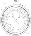
- FIG. 1 is a side view of a tire 1 according to the embodiment.
- the tire 1 is a so-called pneumatic tire that has an inner cavity filled with air at a predetermined pressure.
- the tire 1 of the embodiment is a pneumatic tire for passenger cars including light automobiles, SUVs, and the like.
- the configuration of the tire 1 of the embodiment can also be applied to pneumatic tires for other types of vehicles such as light trucks, trucks, and buses.
- FIG. 1 is a side view of the tire 1 viewed in the direction of a tire rotation axis X.
- the following description will be provided by referring to a tire axial direction, a tire circumferential direction, and a tire radial direction, which are as follows.
- the tire axial direction refers to a direction in which the tire rotation axis X extends, and corresponds to a front-back direction of the page of FIG. 1 .
- the tire axial direction coincides with the left-right direction when the tire 1 is viewed in the tire radial direction, and therefore, the tire axial direction may be referred to as the left-right direction.
- the tire circumferential direction can be represented by an arc line centered on the tire rotation axis X, is a direction along the rotation direction of the tire 1, and is indicated by the arrow G in FIG. 1 .
- the tire radial direction is a direction perpendicular to the tire rotation axis X, and is arbitrarily indicated by the arrow Y in FIG. 1 .
- the tire 1 includes beads 2, sidewalls 3 that continue from the beads 2 and extend outward in the tire radial direction away from the tire rotation axis X, and a tread 4.
- One bead 2 and one sidewall 3 are provided on one side 1s of tire 1 illustrated in FIG. 1
- one bead 2 and one sidewall 3 are provided on the other side of the tire 1 spaced apart in the tire axial direction from the side 1s and not illustrated in FIG. 1 . That is, the tire 1 includes the left and right beads 2 in pairs and the left and right sidewalls 3 in pairs.
- the tread 4 is disposed between the outer sides in the tire radial direction of the left and right sidewalls 3.
- the outer peripheral surface of the tread 4 includes a tread surface that contacts with a road surface.
- the tire 1 is mainly composed of a plurality of types of rubbers respectively constituting the beads 2, the sidewalls 3, and the tread 4.
- a carcass ply that constitutes the skeleton of the tire 1 is disposed on an inner cavity-facing side of the rubber constituting the entire tire 1, and an inner liner that maintains an air pressure is disposed on an inner cavity-facing side of the carcass ply.
- An annular reinforcing belt is embedded in the rubber constituting the tread 4.
- the carcass ply, the inner liner, and the reinforcing belt are not illustrated.
- various components are included as necessary in consideration of the function of the tire 1.
- the sidewall 3 has an outer surface 3a and an annular decorative region 5 extending on the outer surface 3a over the entire circumference in the tire circumferential direction.
- the decorative region 5 has a constant width and is defined between an inner arc line 5a and an outer arc line 5b.
- the inner arc line 5a is located inward in the tire radial direction and close to the tire rotation axis X in the tire radial direction
- the outer arc line 5b is located outward in the tire radial direction with respect to the inner arc line 5a.
- Each of the inner arc line 5a and the outer arc line 5b may be a line formed as a concavity, a convexity, or a step on the outer surface 3a of the sidewall 3, or may be a virtual line that does not actually exist.
- the position of the decorative region 5 may be outside in the tire radial direction with respect to the position of a tire maximum width, or may be at a location including the position of the tire maximum width.
- the position of the tire maximum width refers to a position at which a length in the tire axial direction is maximized between the outer surfaces 3a of the left and right sidewalls 3.
- the tire 1 includes pattern regions 7 on parts of the outer surface 3a of the sidewall 3. Each pattern region 7 is visually recognizable as being different from a region other than the part where the pattern region 7 is provided. Each pattern region 7 is provided on a sidewall rubber that is a black rubber member constituting the outer surface 3a of the sidewall 3.
- mark portions 6A are provided on the annular decorative region 5 at two positions opposite to each other across the tire rotation axis X.
- Each mark portion 6A includes a plurality of characters arranged in the tire circumferential direction. By means of the plurality of characters, at least one of a manufacturer name, a product name, a brand mark, or the like is displayed.
- Each character may be bordered with a concave or convex line, or the entirety of each character may be formed of a concavity or convexity.
- the characters of the mark portions 6A are provided as the pattern regions 7 of the embodiment.
- motif portions 6B are provided on the annular decorative region 5 at two positions each of which is sandwiched between the two mark portions 6A in the circumferential direction.
- Each motif portion 6B includes a motif like a parallelogram curved along the annular decorative region 5.
- the motifs of the motif portions 6B are also provided as the pattern regions 7 of the embodiment.
- the shapes of the pattern regions 7 are not limited to the foregoing shapes, and various shapes may be adopted, examples of which include an arbitrary shape, shapes delineating the above-mentioned manufacturer name, product name, brand mark, etc., and shapes delineating other numerals, characters, etc.
- Each of the pattern regions 7 of the embodiment has a surface 7a extending along the profile of the sidewall 3.
- Each surface 7a has a plurality of projections 20 (to be described later) formed thereon. Due to the plurality of projections 20, each pattern region 7 is visually recognizable as being different from a region other than the pattern region 7.
- FIG. 2 illustrates an example of a tire mold for vulcanization molding the tire 1 of the embodiment.
- FIG. 2 is a meridian sectional view of the tire mold 10, taken along the axial direction of the tire 1 to be molded.
- the tire mold 10 illustrated in FIG. 2 includes a plurality of sectors 11 arranged circumferentially along the outer circumference of the tire 1, a pair of side plates 12 disposed at both axial sides of an annular body formed by the plurality of sectors 11 combined with each other, and a pair of bead rings (not shown).
- an unvulcanized tire 1a to be molded into the tire 1 is set inside the tire mold 10, as indicated by the broken line in FIG. 2 .
- the assembly of the sectors 11, the side plates 12, and the bead rings constitutes the mold for molding the tire 1, and the entire outer surface of the tire 1 is molded by the inner surface of the mold, namely, the inner surfaces 11a of the sectors 11, the inner surfaces 12a of the side plates 12, and the inner surfaces of the bead rings.
- a bladder (not shown) that presses the unvulcanized tire 1a against the inner surface of the tire mold 10 is disposed inside the unvulcanized tire 1a.
- the plurality of sectors 11 mainly play a role in forming the tread 4, and the pair of side plates 12 mainly play a role in forming the sidewalls 3.
- the pair of bead rings play a role in forming the beads 2, and the bladder plays a role in forming the entire inner surface of the tire 1.
- the unvulcanized tire 1a is vulcanized so that the rubbers constituting the entire tire 1 are shaped, and the plurality of projections 20 described below are formed in the pattern regions 7 described above.
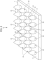
- FIGS. 3 and 4 illustrate the plurality of projections 20 arranged in the pattern region 7.
- FIG. 3 is a perspective view of the projections 20, and
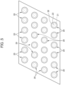
- FIG. 4 is a plan view and illustrates the projections 20 viewed along the arrow IV in FIG. 3 .
- the plurality of projections 20 are disposed on the surface 7a of each pattern region 7 so that the entirety of the pattern region 7 is filled with the projections 20.
- the surface 7a of the pattern region 7 may be referred to as the pattern region surface 7a.
- the plurality of projections 20 are arranged in rows and lines on the pattern region surface 7a.
- the plurality of projections 20 are linearly aligned in lateral rows in the left-right direction and vertical lines in the up-down direction at equal pitches.
- a pitch of the straight lines and rows is 2.0 times or more and 3.0 times or less the equivalent circle diameter of the bottom surface 21.
- the arrangement of the plurality of projections 20 illustrated in FIG. 4 is a non-limiting-example.
- the plurality of projections 20 may be arranged in a staggered manner as illustrated in FIG. 5 . Specifically, in FIG.
- the projections 20 are aligned in a plurality of lateral straight lines arranged at equal pitches in the up-down direction such that between a pair of the lateral lines adjacent to each other in the up-down direction, each of the projections 20 in one lateral line is positioned between the projections 20 in the other lateral line.
- Each of the projections 20 of the embodiment is a minute projection that projects from the pattern region surface 7a.
- FIG. 6 is a perspective view of one projection 20
- FIG. 7 is a side view of a pair of projections 20 adjacent to each other on the pattern region surface 7a.
- each projection 20 includes a bottom surface 21, a leading end 22 farthest from the bottom surface 21, and a barrel 30 connecting the bottom surface 21 and the leading end 22.
- Each projection 20 of the embodiment has a generally acorn-shaped appearance because of the shape of the barrel 30.
- the bottom surface 21 is a virtual surface that is integrated and coplanar with the pattern region surface 7a.
- the bottom surface 21 of the projection 20 of the embodiment has a substantially perfect circular shape.
- each projection 20 has a center axis 20c that connects the center of the bottom surface 21 and the leading end 22 and that is substantially perpendicular to the pattern region surface 7a and the bottom surface 21. Therefore, the projection 20 stands upright with respect to the pattern region surface 7a.
- the distance along the center axis 20c from the bottom surface 21 to the leading end 22 is the height H of the projection 20, and the height H is the shortest distance from the bottom surface 21 to the leading end 22.
- the projection 20 has transverse cross sections with a substantially perfect circular shape over the entire length in the height direction from the bottom surface 21 to the leading end 22.
- the transverse cross section as used herein refers to a plane substantially perpendicular to the center axis 20c, and is substantially parallel to the pattern region surface 7a.
- the barrel 30 of the projection 20 of the embodiment has a bulging portion 23 in the middle in the height direction.
- the bulging portion 23 has a transverse cross section that is larger in equivalent circle diameter than the bottom surface 21 and is the largest in equivalent circle diameter in the projection 20.
- the bulging portion 23 is a portion of the barrel 30 that bulges most in the lateral direction. Since the projection 20 of the embodiment has, in its entirety, transverse cross sections with a substantially perfect circular shape, the equivalent circle diameter is the diameter.
- the barrel 30 of the projection 20 of the embodiment includes a bottom surface side barrel portion 32 and a leading end side barrel portion 31 with the bulging portion 23 interposed therebetween as a boundary.
- the bottom surface side barrel portion 32 is a portion below the bulging portion 23, that is, a portion from the bulging portion 23 to the bottom surface 21.
- the transverse cross section of the bottom surface side barrel portion 32 gradually decreases in area from the bulging portion 23 toward the bottom surface 21.
- the leading end side barrel portion 31 is a portion above the bulging portion 23, that is, a portion from the bulging portion 23 to the leading end 22.
- the transverse cross section of the leading end side barrel portion 31 gradually decreases in area from the bulging portion 23 toward the leading end 22. That is, the bottom surface side barrel portion 32 has a shape that narrows toward the bottom surface 21, and the leading end side barrel portion 31 has a shape that narrows toward the leading end 22.
- the leading end side barrel portion 31 converges in the direction from the bulging portion 23 toward the leading end 22, and the leading end 22 of the projection 20 has a shape that tapers to a sharp point.
- the shape of the leading end 22 is not limited to this, and may have a hemispherical shape, for example. Alternatively, the leading end 22 may have the tip with a flat portion which would result from cutting substantially parallel to the transverse cross section.
- the plurality of projections 20 of the embodiment have a substantially uniform shape and size.
- the dimensions specifying the shape and the like of the projections 20 of the embodiment are not particularly limited, and may be within the following preferred ranges, for example.
- the height of the projection 20 is preferably, for example, 2.0 times or more and 3.0 times or less the diameter (denoted by ⁇ B in FIGS. 6 and 7 ) of the bottom surface 21. Specifically, the height of the projection 20 is preferably 0.2 mm or greater and 0.8 mm or less.
- the diameter (denoted by ⁇ M in FIGS. 6 and 7 ) of the transverse cross section of the bulging portion 23 of the projection 20 of the embodiment is preferably 120% or more and 150% or less of the diameter of the bottom surface 21.
- the diameter of the transverse cross section of the bottom surface 21 is preferably, for example, 0.1 mm or greater and 0.4 mm or less
- the diameter of the transverse cross section of the bulging portion 23 is preferably, for example, 0.2 mm or greater and 0.5 mm or less.
- the center of the projection 20 of the embodiment in the height direction is denoted by H1
- the height position of the bulging portion 23 in terms of the height H of the projection 20 is preferably within a range denoted by H2, which is between a height position closer to the bottom surface 21 by 15% of the height of the projection 20 from the center H1 and a height position closer to the leading end 22 by 15% of the height of the projection 20 from the center H1.
- the plurality of projections 20 on the pattern region surface 7a are preferably arranged at a density of two or more projections 20 per 1 mm 2 . Furthermore, as illustrated in FIG. 7 , it is preferable that the interval P between mutually proximate portions of the adjacent projections 20 is, for example, 0.5 mm or less.
- the plurality of projections 20 of the embodiment can be formed on the pattern region surface 7a by using the tire mold 10 described above, for example.
- a plurality of concavities corresponding to the projections 20 and capable of molding the projections 20 are formed in the inner surface 12a, which is a tire molding surface of the side plate 12 and is for forming the pattern regions 7.
- any method can be employed to form the plurality of concavities
- laser processing in which portions of the inner surface 12a of the side plate 12 are removed by irradiating the inner surface 12a with a laser beam is suitable as the method of forming the concavities.
- a removal processing using a pulse fiber laser can be adopted, for example.
- Suitable conditions of the laser processing are as follows: a center wavelength is 1080 nm, an average output is 100 W or greater and 300 W or less, and a laser spot diameter is about 0.05 mm.
- the concavities by which the projections 20 of the embodiment can be molded by adjusting an output for each pulse and adjusting an irradiation angle of the laser beam.
- the projections 20 are molded using the tire mold 10 since the projections 20 of the embodiment have a so-called undercut shape, there may be a concern that the projections 20 cannot be removed from the concavities in which the projections 20 have been molded, at the time of releasing the tire from the tire mold 10.
- setting the diameter of the bulging portion 23 to, for example, about 150% or less of the diameter of the bottom surface 21 makes it possible to remove the projections 20 without trouble, with the help of elastic deformation of the rubber.
- time and manpower are required to, for example, divide the tire mold 10 in order to enable removal of the projections 20 from the mold.
- the tire 1 of the embodiment has the plurality of projections 20 arranged in the pattern regions 7 as described above, light incident on each pattern region 7 is mainly incident on the pattern region surface 7a and the barrels 30 of the projections 20, and is reflected by their surfaces. The reflected light is reflected again by the surrounding projections 20 and the pattern region surface 7a, whereby such reflection repeatedly occurs between the plurality of projections 20 and between the pattern region surface 7a and the projections 20. As a result, the light incident on the pattern region 7 is gradually attenuated and absorbed.
- the pattern region 7 having the configuration described above is visually recognized as being blacker than the outer surface 3a of the sidewall 3 that reflects ambient light around the pattern region 7.
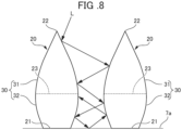
- FIG. 8 schematically illustrates an example of a light-absorbing effect according to the embodiment.
- the light denoted by L in FIG. 8 travels toward the pattern region surface 7a, the light is reflected in a zigzag between the barrels 30 of a pair of adjacent projections 20 before reaching the vicinity of the pattern region surface 7a, and then, is reflected by the pattern region surface 7a.
- the light reflected by the pattern region surface 7a reaches the bottom surface side barrel portions 32 of the barrels 30 of the projections 20.
- the bottom surface side barrel portion 32 narrows toward the bottom surface 21, the light reflected by the bottom surface side barrel portion 32 is likely to travel toward the pattern region surface 7a.
- the light that has reached the pattern region surface 7a is blocked by the bottom surface side barrel portions 32 of the projections 20 to be confined in the pattern region 7, and is less likely to exit to the outside from the pattern region 7, that is, is less likely to be reflected to the outside.
- an effect in absorbing light incident on the pattern region 7 is promoted, and a high contrast is achieved due to an increase in the black color intensity.
- the pattern region 7 which has the plurality of projections 20 arranged therein, is mainly incident on the pattern region surface 7a and the barrels 30 of the projections 20, and is reflected by their surfaces.
- the reflected light is reflected again by the surrounding projections 20 and the pattern region surface 7a, and such reflection repeatedly occurs between the plurality of projections 20 and between the pattern region surface 7a and the projections 20.
- the light incident on the pattern region 7 is gradually attenuated and absorbed.
- the pattern region 7 having this configuration is visually recognized as being blacker than the outer surface 3a of the sidewall 3 that reflects ambient light around the pattern region 7.
- each projection 20 of the embodiment has the bottom surface side barrel portion 32 extending from the bulging portion 23 to the bottom surface 21 and having a shape that narrows toward the bottom surface 21, the light that has once entered the pattern region 7 is confined in the pattern region 7 by the bottom surface side barrel portions 32 and is less likely to exit to the outside, and thus, is less likely to be reflected to the outside. As a result, an effect in absorbing light incident on the pattern region 7 is promoted, and a high contrast is achieved due to the pattern region 7 having a higher black color intensity than the known art.
- the equivalent circle diameter of the transverse cross section of the bulging portion 23 is 120% or greater and 150% or less of the equivalent circle diameter of the bottom surface 21.
- the bulging portion 23 having a larger diameter than the bottom surface 21 is reliably formed, and as a result, the light-absorbing effect by the bottom surface side barrel portion 32 is enhanced. Furthermore, as described above, in the case where the projections 20 are molded by the concavities formed in the tire mold 10, the projections 20 can be removed from the tire mold 10 even if they have an undercut shape.
- each projection 20 has a height that is the shortest distance from the bottom surface 21 to the leading end 22, and that the height position of the bulging portion 23 with respect to the height of the projection 20 is located between a height position closer to the bottom surface 21 by 15% of the height of the projection 20 from a center of the projection 20 in a height direction and a height position closer to the leading end 22 by 15% of the height of the projection 20 from the center of the projection 20 in the height direction.
- the height position of the bulging portion 23 of each projection 20 is appropriately set, and the light-absorbing effect by the bottom surface side barrel portions 32 is enhanced.
- the plurality of projections 20 are arranged at a density of two or more projections 20 per 1 mm 2 in the pattern region 7.
- the plurality of projections 20 are arranged at equal intervals in straight lines and rows, and the pitch of the straight lines and rows is 2.0 times or more and 3.0 times or less the equivalent circle diameter of the bottom surface 21.
- each projection 20 has a substantially circular shape.
- the leading end 22 has a shape that tapers to a sharp point.
- the plurality of projections 20 may be randomly disposed in an irregular arrangement in the pattern region 7, instead of the line and row arrangement illustrated in FIGS. 4 and 5 .
- each projection 20 of the above embodiment stands upright on the pattern region surface 7a, each projection 20 may be tilted while having the center axis 20c tilted with respect to the pattern region surface 7a.
- the shapes and dimensions of the plurality of projections 20 of the above embodiment are substantially uniform, the shapes and dimensions of the plurality of projections 20 may be non-uniform.
- the projections 20 may have different heights, the bottom surfaces 21 with different diameters, the bulging portions 23 with different diameters and at different height positions, etc.
Landscapes
- Engineering & Computer Science (AREA)
- Mechanical Engineering (AREA)
- Tires In General (AREA)
Abstract
Description
- The present invention relates to a tire having, on a part of an outer surface of a sidewall, a pattern region for displaying, for example, a mark, a pattern, and the like.
- There is a known tire having, on a part of a sidewall, a pattern region in which a large number of fine projections are aggregated (for example,
Japanese Unexamined Patent Application, Publication No. 2017-1440 - Patent Document 1:
Japanese Unexamined Patent Application, Publication No. 2017-1440 - The high contrast obtained by a large number of projections has an advantage that it is less susceptible to changes due to aging than contrast obtained by other means such as painting or the like, and its effect is exerted over a long period of time. Therefore, there is a demand for formation of a pattern region including projections, having a higher black color intensity and a higher contrast than the known art, and contributing to further improvement of the design effect and the appearance.
- It is an object of the present invention to provide a tire having a higher black color intensity and a higher contrast than the known art.
- A tire according to an embodiment of the present invention includes a pattern region on a part of an outer surface of a sidewall of the tire, the pattern region being visually recognizable as being different from a region other than the part. The pattern region includes a plurality of projections projecting from a surface of the pattern region, and each of the plurality of projections includes: a bottom surface integrated with the surface of the pattern region; a leading end farthest from the bottom surface; and a barrel connecting the bottom surface and the leading end. The barrel includes: a bulging portion provided between the bottom surface and the leading end and having a transverse cross section with an equivalent circle diameter that is larger than an equivalent circle diameter of the bottom surface and is largest in the projection; a bottom surface side barrel portion provided from the bulging portion to the bottom surface and having a transverse cross section that gradually decreases in area from the bulging portion toward the bottom surface; and a leading end side barrel portion provided from the bulging portion to the leading end and having a transverse cross section that gradually decreases in area from the bulging portion toward the leading end.
- The present invention provides a tire having a higher black color intensity and a higher contrast than the known art.
-
-
FIG. 1 is a side view of a tire according to an embodiment; -
FIG. 2 is a cross-sectional view illustrating an example of a mold for vulcanization molding the tire according to the embodiment; -
FIG. 3 is a perspective view illustrating a state in which a plurality of projections are arranged in a pattern region of the tire according to the embodiment; -
FIG. 4 illustrates the plurality of projections viewed along the arrow IV inFIG. 3 ; -
FIG. 5 is a plan view illustrating another example of arrangement of a plurality of projections in the pattern region; -
FIG. 6 is a perspective view of the projection according to the embodiment; -
FIG. 7 is a side view of a pair of adjacent projections according to the embodiment; and -
FIG. 8 is a side view of a pair of adjacent projections according to the embodiment, and schematically illustrates a light-absorbing effect by the projections. - An embodiment of the present invention will be described below with reference to the drawings. It should be noted that the word "substantially" used in the present specification specifies not only the state of interest in the strict sense, but also a state that is approximate to the state of interest and is within a range where the functions and effects of the state of interest can be achieved.
-
FIG. 1 is a side view of atire 1 according to the embodiment. Thetire 1 is a so-called pneumatic tire that has an inner cavity filled with air at a predetermined pressure. Thetire 1 of the embodiment is a pneumatic tire for passenger cars including light automobiles, SUVs, and the like. The configuration of thetire 1 of the embodiment can also be applied to pneumatic tires for other types of vehicles such as light trucks, trucks, and buses. - First, with reference to
FIG. 1 , an overview of a configuration mainly related to a side surface of thetire 1 will be described.FIG. 1 is a side view of thetire 1 viewed in the direction of a tire rotation axis X. The following description will be provided by referring to a tire axial direction, a tire circumferential direction, and a tire radial direction, which are as follows. The tire axial direction refers to a direction in which the tire rotation axis X extends, and corresponds to a front-back direction of the page ofFIG. 1 . The tire axial direction coincides with the left-right direction when thetire 1 is viewed in the tire radial direction, and therefore, the tire axial direction may be referred to as the left-right direction. The tire circumferential direction can be represented by an arc line centered on the tire rotation axis X, is a direction along the rotation direction of thetire 1, and is indicated by the arrow G inFIG. 1 . The tire radial direction is a direction perpendicular to the tire rotation axis X, and is arbitrarily indicated by the arrow Y inFIG. 1 . - As illustrated in
FIG. 1 , thetire 1 includesbeads 2,sidewalls 3 that continue from thebeads 2 and extend outward in the tire radial direction away from the tire rotation axis X, and atread 4. Onebead 2 and onesidewall 3 are provided on oneside 1s oftire 1 illustrated inFIG. 1 , and onebead 2 and onesidewall 3 are provided on the other side of thetire 1 spaced apart in the tire axial direction from theside 1s and not illustrated inFIG. 1 . That is, thetire 1 includes the left andright beads 2 in pairs and the left andright sidewalls 3 in pairs. Thetread 4 is disposed between the outer sides in the tire radial direction of the left andright sidewalls 3. The outer peripheral surface of thetread 4 includes a tread surface that contacts with a road surface. - The
tire 1 is mainly composed of a plurality of types of rubbers respectively constituting thebeads 2, thesidewalls 3, and thetread 4. A carcass ply that constitutes the skeleton of thetire 1 is disposed on an inner cavity-facing side of the rubber constituting theentire tire 1, and an inner liner that maintains an air pressure is disposed on an inner cavity-facing side of the carcass ply. An annular reinforcing belt is embedded in the rubber constituting thetread 4. The carcass ply, the inner liner, and the reinforcing belt are not illustrated. In addition to the foregoing components, various components are included as necessary in consideration of the function of thetire 1. - As illustrated in
FIG. 1 , thesidewall 3 has anouter surface 3a and an annulardecorative region 5 extending on theouter surface 3a over the entire circumference in the tire circumferential direction. Thedecorative region 5 has a constant width and is defined between aninner arc line 5a and anouter arc line 5b. Theinner arc line 5a is located inward in the tire radial direction and close to the tire rotation axis X in the tire radial direction, and theouter arc line 5b is located outward in the tire radial direction with respect to theinner arc line 5a. Each of theinner arc line 5a and theouter arc line 5b may be a line formed as a concavity, a convexity, or a step on theouter surface 3a of thesidewall 3, or may be a virtual line that does not actually exist. - On the
outer surface 3a of thesidewall 3, the position of thedecorative region 5 may be outside in the tire radial direction with respect to the position of a tire maximum width, or may be at a location including the position of the tire maximum width. The position of the tire maximum width refers to a position at which a length in the tire axial direction is maximized between theouter surfaces 3a of the left andright sidewalls 3. - The
tire 1 includespattern regions 7 on parts of theouter surface 3a of thesidewall 3. Eachpattern region 7 is visually recognizable as being different from a region other than the part where thepattern region 7 is provided. Eachpattern region 7 is provided on a sidewall rubber that is a black rubber member constituting theouter surface 3a of thesidewall 3. - As illustrated in
FIG. 1 ,mark portions 6A are provided on the annulardecorative region 5 at two positions opposite to each other across the tire rotation axis X. Eachmark portion 6A includes a plurality of characters arranged in the tire circumferential direction. By means of the plurality of characters, at least one of a manufacturer name, a product name, a brand mark, or the like is displayed. Each character may be bordered with a concave or convex line, or the entirety of each character may be formed of a concavity or convexity. For example, the characters of themark portions 6A are provided as thepattern regions 7 of the embodiment. - As illustrated in
FIG. 1 ,motif portions 6B are provided on the annulardecorative region 5 at two positions each of which is sandwiched between the twomark portions 6A in the circumferential direction. Eachmotif portion 6B includes a motif like a parallelogram curved along the annulardecorative region 5. For example, the motifs of themotif portions 6B are also provided as thepattern regions 7 of the embodiment. - It should be noted that the shapes of the
pattern regions 7 are not limited to the foregoing shapes, and various shapes may be adopted, examples of which include an arbitrary shape, shapes delineating the above-mentioned manufacturer name, product name, brand mark, etc., and shapes delineating other numerals, characters, etc. - Each of the
pattern regions 7 of the embodiment has asurface 7a extending along the profile of thesidewall 3. Eachsurface 7a has a plurality of projections 20 (to be described later) formed thereon. Due to the plurality ofprojections 20, eachpattern region 7 is visually recognizable as being different from a region other than thepattern region 7. -
FIG. 2 illustrates an example of a tire mold for vulcanization molding thetire 1 of the embodiment.FIG. 2 is a meridian sectional view of thetire mold 10, taken along the axial direction of thetire 1 to be molded. - The
tire mold 10 illustrated inFIG. 2 includes a plurality ofsectors 11 arranged circumferentially along the outer circumference of thetire 1, a pair ofside plates 12 disposed at both axial sides of an annular body formed by the plurality ofsectors 11 combined with each other, and a pair of bead rings (not shown). At the time of vulcanization molding, anunvulcanized tire 1a to be molded into thetire 1 is set inside thetire mold 10, as indicated by the broken line inFIG. 2 . The assembly of thesectors 11, theside plates 12, and the bead rings constitutes the mold for molding thetire 1, and the entire outer surface of thetire 1 is molded by the inner surface of the mold, namely, theinner surfaces 11a of thesectors 11, theinner surfaces 12a of theside plates 12, and the inner surfaces of the bead rings. During vulcanization molding, a bladder (not shown) that presses theunvulcanized tire 1a against the inner surface of thetire mold 10 is disposed inside theunvulcanized tire 1a. The plurality ofsectors 11 mainly play a role in forming thetread 4, and the pair ofside plates 12 mainly play a role in forming thesidewalls 3. The pair of bead rings play a role in forming thebeads 2, and the bladder plays a role in forming the entire inner surface of thetire 1. - In the
tire mold 10, theunvulcanized tire 1a is vulcanized so that the rubbers constituting theentire tire 1 are shaped, and the plurality ofprojections 20 described below are formed in thepattern regions 7 described above. -
FIGS. 3 and4 illustrate the plurality ofprojections 20 arranged in thepattern region 7. Specifically,FIG. 3 is a perspective view of theprojections 20, andFIG. 4 is a plan view and illustrates theprojections 20 viewed along the arrow IV inFIG. 3 . The plurality ofprojections 20 are disposed on thesurface 7a of eachpattern region 7 so that the entirety of thepattern region 7 is filled with theprojections 20. Hereinafter, thesurface 7a of thepattern region 7 may be referred to as thepattern region surface 7a. - As illustrated in
FIG. 4 , the plurality ofprojections 20 are arranged in rows and lines on thepattern region surface 7a. InFIG. 4 , the plurality ofprojections 20 are linearly aligned in lateral rows in the left-right direction and vertical lines in the up-down direction at equal pitches. For example, a pitch of the straight lines and rows is 2.0 times or more and 3.0 times or less the equivalent circle diameter of thebottom surface 21. The arrangement of the plurality ofprojections 20 illustrated inFIG. 4 is a non-limiting-example. For example, the plurality ofprojections 20 may be arranged in a staggered manner as illustrated inFIG. 5 . Specifically, inFIG. 5 , theprojections 20 are aligned in a plurality of lateral straight lines arranged at equal pitches in the up-down direction such that between a pair of the lateral lines adjacent to each other in the up-down direction, each of theprojections 20 in one lateral line is positioned between theprojections 20 in the other lateral line. - Each of the
projections 20 of the embodiment is a minute projection that projects from thepattern region surface 7a.FIG. 6 is a perspective view of oneprojection 20, andFIG. 7 is a side view of a pair ofprojections 20 adjacent to each other on thepattern region surface 7a. As illustrated inFIGS. 6 and 7 , eachprojection 20 includes abottom surface 21, a leadingend 22 farthest from thebottom surface 21, and abarrel 30 connecting thebottom surface 21 and theleading end 22. Eachprojection 20 of the embodiment has a generally acorn-shaped appearance because of the shape of thebarrel 30. Thebottom surface 21 is a virtual surface that is integrated and coplanar with thepattern region surface 7a. - The
bottom surface 21 of theprojection 20 of the embodiment has a substantially perfect circular shape. As illustrated inFIG. 7 , eachprojection 20 has acenter axis 20c that connects the center of thebottom surface 21 and theleading end 22 and that is substantially perpendicular to thepattern region surface 7a and thebottom surface 21. Therefore, theprojection 20 stands upright with respect to thepattern region surface 7a. As shown inFIG. 7 , the distance along thecenter axis 20c from thebottom surface 21 to theleading end 22 is the height H of theprojection 20, and the height H is the shortest distance from thebottom surface 21 to theleading end 22. Theprojection 20 has transverse cross sections with a substantially perfect circular shape over the entire length in the height direction from thebottom surface 21 to theleading end 22. The transverse cross section as used herein refers to a plane substantially perpendicular to thecenter axis 20c, and is substantially parallel to thepattern region surface 7a. - The
barrel 30 of theprojection 20 of the embodiment has a bulgingportion 23 in the middle in the height direction. The bulgingportion 23 has a transverse cross section that is larger in equivalent circle diameter than thebottom surface 21 and is the largest in equivalent circle diameter in theprojection 20. In other words, the bulgingportion 23 is a portion of thebarrel 30 that bulges most in the lateral direction. Since theprojection 20 of the embodiment has, in its entirety, transverse cross sections with a substantially perfect circular shape, the equivalent circle diameter is the diameter. In the present disclosure, the transverse cross section of theprojections 20 is not limited to the perfect circle shape, and may be, for example, an elliptical shape, a triangular shape, a polygonal shape, or the like, and the equivalent circle diameter is adopted to the transverse cross sections of these shapes. - The
barrel 30 of theprojection 20 of the embodiment includes a bottom surfaceside barrel portion 32 and a leading endside barrel portion 31 with the bulgingportion 23 interposed therebetween as a boundary. InFIGS. 6 and 7 , the bottom surfaceside barrel portion 32 is a portion below the bulgingportion 23, that is, a portion from the bulgingportion 23 to thebottom surface 21. The transverse cross section of the bottom surfaceside barrel portion 32 gradually decreases in area from the bulgingportion 23 toward thebottom surface 21. InFIGS. 6 and 7 , the leading endside barrel portion 31 is a portion above the bulgingportion 23, that is, a portion from the bulgingportion 23 to theleading end 22. The transverse cross section of the leading endside barrel portion 31 gradually decreases in area from the bulgingportion 23 toward the leadingend 22. That is, the bottom surfaceside barrel portion 32 has a shape that narrows toward thebottom surface 21, and the leading endside barrel portion 31 has a shape that narrows toward the leadingend 22. - The leading end
side barrel portion 31 converges in the direction from the bulgingportion 23 toward the leadingend 22, and theleading end 22 of theprojection 20 has a shape that tapers to a sharp point. The shape of theleading end 22 is not limited to this, and may have a hemispherical shape, for example. Alternatively, the leadingend 22 may have the tip with a flat portion which would result from cutting substantially parallel to the transverse cross section. - As illustrated in
FIG. 3 , the plurality ofprojections 20 of the embodiment have a substantially uniform shape and size. The dimensions specifying the shape and the like of theprojections 20 of the embodiment are not particularly limited, and may be within the following preferred ranges, for example. - The height of the
projection 20 is preferably, for example, 2.0 times or more and 3.0 times or less the diameter (denoted by ϕB inFIGS. 6 and 7 ) of thebottom surface 21. Specifically, the height of theprojection 20 is preferably 0.2 mm or greater and 0.8 mm or less. - The diameter (denoted by ϕM in
FIGS. 6 and 7 ) of the transverse cross section of the bulgingportion 23 of theprojection 20 of the embodiment is preferably 120% or more and 150% or less of the diameter of thebottom surface 21. Specifically, the diameter of the transverse cross section of thebottom surface 21 is preferably, for example, 0.1 mm or greater and 0.4 mm or less, and the diameter of the transverse cross section of the bulgingportion 23 is preferably, for example, 0.2 mm or greater and 0.5 mm or less. - As illustrated in
FIG. 7 , the center of theprojection 20 of the embodiment in the height direction is denoted by H1, and the height position of the bulgingportion 23 in terms of the height H of theprojection 20 is preferably within a range denoted by H2, which is between a height position closer to thebottom surface 21 by 15% of the height of theprojection 20 from the center H1 and a height position closer to theleading end 22 by 15% of the height of theprojection 20 from the center H1. - The plurality of
projections 20 on thepattern region surface 7a are preferably arranged at a density of two ormore projections 20 per 1 mm2. Furthermore, as illustrated inFIG. 7 , it is preferable that the interval P between mutually proximate portions of theadjacent projections 20 is, for example, 0.5 mm or less. - The plurality of
projections 20 of the embodiment can be formed on thepattern region surface 7a by using thetire mold 10 described above, for example. To form the plurality ofprojections 20 by thetire mold 10, a plurality of concavities corresponding to theprojections 20 and capable of molding theprojections 20 are formed in theinner surface 12a, which is a tire molding surface of theside plate 12 and is for forming thepattern regions 7. - In this case, although any method can be employed to form the plurality of concavities, laser processing in which portions of the
inner surface 12a of theside plate 12 are removed by irradiating theinner surface 12a with a laser beam is suitable as the method of forming the concavities. As the laser processing, a removal processing using a pulse fiber laser can be adopted, for example. Suitable conditions of the laser processing are as follows: a center wavelength is 1080 nm, an average output is 100 W or greater and 300 W or less, and a laser spot diameter is about 0.05 mm. - In the case of using the laser processing, it is possible to form in the
tire mold 10 the concavities by which theprojections 20 of the embodiment can be molded by adjusting an output for each pulse and adjusting an irradiation angle of the laser beam. - In the case where the
projections 20 are molded using thetire mold 10, since theprojections 20 of the embodiment have a so-called undercut shape, there may be a concern that theprojections 20 cannot be removed from the concavities in which theprojections 20 have been molded, at the time of releasing the tire from thetire mold 10. In that case, setting the diameter of the bulgingportion 23 to, for example, about 150% or less of the diameter of thebottom surface 21 makes it possible to remove theprojections 20 without trouble, with the help of elastic deformation of the rubber. Thus, it is possible to avoid a situation in which time and manpower are required to, for example, divide thetire mold 10 in order to enable removal of theprojections 20 from the mold. - Since the
tire 1 of the embodiment has the plurality ofprojections 20 arranged in thepattern regions 7 as described above, light incident on eachpattern region 7 is mainly incident on thepattern region surface 7a and thebarrels 30 of theprojections 20, and is reflected by their surfaces. The reflected light is reflected again by the surroundingprojections 20 and thepattern region surface 7a, whereby such reflection repeatedly occurs between the plurality ofprojections 20 and between thepattern region surface 7a and theprojections 20. As a result, the light incident on thepattern region 7 is gradually attenuated and absorbed. Thepattern region 7 having the configuration described above is visually recognized as being blacker than theouter surface 3a of thesidewall 3 that reflects ambient light around thepattern region 7. -
FIG. 8 schematically illustrates an example of a light-absorbing effect according to the embodiment. When the light denoted by L inFIG. 8 travels toward thepattern region surface 7a, the light is reflected in a zigzag between thebarrels 30 of a pair ofadjacent projections 20 before reaching the vicinity of thepattern region surface 7a, and then, is reflected by thepattern region surface 7a. The light reflected by thepattern region surface 7a reaches the bottom surfaceside barrel portions 32 of thebarrels 30 of theprojections 20. Here, since the bottom surfaceside barrel portion 32 narrows toward thebottom surface 21, the light reflected by the bottom surfaceside barrel portion 32 is likely to travel toward thepattern region surface 7a. Therefore, the light that has reached thepattern region surface 7a is blocked by the bottom surfaceside barrel portions 32 of theprojections 20 to be confined in thepattern region 7, and is less likely to exit to the outside from thepattern region 7, that is, is less likely to be reflected to the outside. As a result, an effect in absorbing light incident on thepattern region 7 is promoted, and a high contrast is achieved due to an increase in the black color intensity. - The embodiment described above exerts the following effects.
- (1) The
tire 1 according to the embodiment is a tire including apattern region 7 on anouter surface 3a of asidewall 3 of thetire 1, thepattern region 7 being visually recognizable as being different from a region other than thepattern region 7 in theouter surface 3a of thesidewall 3, and including a plurality ofprojections 20 projecting from asurface 7a of thepattern region 7. Each of the plurality ofprojections 20 includes abottom surface 21 integrated with thesurface 7a of thepattern region 7, a leadingend 22 farthest from thebottom surface 21, and abarrel 30 connecting thebottom surface 21 and theleading end 22. Thebarrel 30 includes: a bulgingportion 23 provided between thebottom surface 21 and theleading end 22 and having a transverse cross section with an equivalent circle diameter that is larger than an equivalent circle diameter of thebottom surface 21 and is the largest in theprojection 20; a bottom surfaceside barrel portion 32 provided from the bulgingportion 23 to thebottom surface 21 and having a transverse cross section that gradually decreases in area from the bulgingportion 23 toward thebottom surface 21; and a leading endside barrel portion 31 provided from the bulgingportion 23 to theleading end 22 and having a transverse cross section that gradually decreases in area from the bulgingportion 23 toward the leadingend 22. - According to the
tire 1 of the embodiment, light incident on thepattern region 7, which has the plurality ofprojections 20 arranged therein, is mainly incident on thepattern region surface 7a and thebarrels 30 of theprojections 20, and is reflected by their surfaces. The reflected light is reflected again by the surroundingprojections 20 and thepattern region surface 7a, and such reflection repeatedly occurs between the plurality ofprojections 20 and between thepattern region surface 7a and theprojections 20. As a result, the light incident on thepattern region 7 is gradually attenuated and absorbed. When thepattern region 7 having this configuration is visually recognized as being blacker than theouter surface 3a of thesidewall 3 that reflects ambient light around thepattern region 7. Since eachprojection 20 of the embodiment has the bottom surfaceside barrel portion 32 extending from the bulgingportion 23 to thebottom surface 21 and having a shape that narrows toward thebottom surface 21, the light that has once entered thepattern region 7 is confined in thepattern region 7 by the bottom surfaceside barrel portions 32 and is less likely to exit to the outside, and thus, is less likely to be reflected to the outside. As a result, an effect in absorbing light incident on thepattern region 7 is promoted, and a high contrast is achieved due to thepattern region 7 having a higher black color intensity than the known art. - (2) In the
tire 1 according to the embodiment described in (1) above, it is preferable that the equivalent circle diameter of the transverse cross section of the bulgingportion 23 is 120% or greater and 150% or less of the equivalent circle diameter of thebottom surface 21. - Due to this feature, the bulging
portion 23 having a larger diameter than thebottom surface 21 is reliably formed, and as a result, the light-absorbing effect by the bottom surfaceside barrel portion 32 is enhanced. Furthermore, as described above, in the case where theprojections 20 are molded by the concavities formed in thetire mold 10, theprojections 20 can be removed from thetire mold 10 even if they have an undercut shape. - (3) In the
tire 1 according to the embodiment described in (1) and (2) above, it is preferable that eachprojection 20 has a height that is the shortest distance from thebottom surface 21 to theleading end 22, and that the height position of the bulgingportion 23 with respect to the height of theprojection 20 is located between a height position closer to thebottom surface 21 by 15% of the height of theprojection 20 from a center of theprojection 20 in a height direction and a height position closer to theleading end 22 by 15% of the height of theprojection 20 from the center of theprojection 20 in the height direction. - Due to this feature, the height position of the bulging
portion 23 of eachprojection 20 is appropriately set, and the light-absorbing effect by the bottom surfaceside barrel portions 32 is enhanced. - (4) In the
tire 1 according to the embodiment described in (1) to (3) above, it is preferable that the plurality ofprojections 20 are arranged at a density of two ormore projections 20 per 1 mm2 in thepattern region 7. - Due to this feature, a light-absorbing effect is enhanced between the
adjacent projections 20, and a high contrast is achieved due to thepattern region 7 having a higher black color intensity than the known art. - (5) In the
tire 1 according to the embodiment described in (1) to (4) above, it is preferable that the plurality ofprojections 20 are arranged at equal intervals in straight lines and rows, and the pitch of the straight lines and rows is 2.0 times or more and 3.0 times or less the equivalent circle diameter of thebottom surface 21. - Due to this feature, a light-absorbing effect is enhanced between the
adjacent projections 20, and a high contrast is achieved due to thepattern region 7 having a higher black color intensity than the known art. - (6) In the
tire 1 according to the embodiment described in (1) to (5) above, it is preferable that the transverse cross section of eachprojection 20 has a substantially circular shape. - Due to this feature, light is reflected by each
projection 20 radially around theprojection 20, and consequently, the reflection of light repeated between theprojections 20 is likely to be complicated. Furthermore, an effect in confining light incident on thepattern region 7 in thepattern region 7 is likely to be exerted. For these reasons, the light-absorbing effect is enhanced, and a high contrast is achieved due to thepattern region 7 having a higher black color intensity than the known art. - (7) In the
tire 1 according to the embodiment described in (1) to (6) above, it is preferable that the leadingend 22 has a shape that tapers to a sharp point. - Due to this feature, light incident on the
pattern region 7 is less likely to be reflected by the leading ends of theprojections 20, and an amount of light reflected to the outside is reduced as compared with the case where the leading end is not sharply pointed. As a result, a high contrast is achieved in thepattern region 7. - It should be noted that the present invention is not limited to the embodiment described above, and modifications, improvements, and the like within a range in which the object of the present invention can be achieved are also encompassed in the scope of the present invention.
- For example, the plurality of
projections 20 may be randomly disposed in an irregular arrangement in thepattern region 7, instead of the line and row arrangement illustrated inFIGS. 4 and5 . - Although each
projection 20 of the above embodiment stands upright on thepattern region surface 7a, eachprojection 20 may be tilted while having thecenter axis 20c tilted with respect to thepattern region surface 7a. - Although the shapes and dimensions of the plurality of
projections 20 of the above embodiment are substantially uniform, the shapes and dimensions of the plurality ofprojections 20 may be non-uniform. For example, theprojections 20 may have different heights, the bottom surfaces 21 with different diameters, the bulgingportions 23 with different diameters and at different height positions, etc. -
- 1: Tire
- 3: Sidewall
- 3a: Outer surface of sidewall
- 7: Pattern region
- 7a: Surface of Pattern Region
- 20: Projection
- 21: Bottom surface
- 22: Leading end
- 23: Bulging portion
- 30: Barrel
- 31: Leading end side barrel portion
- 32: Bottom surface side barrel portion
Claims (7)
- A tire (1) comprising:a pattern region (7) on an outer surface (3a) of a sidewall (3) of the tire (1), the pattern region (7) being visually recognizable as being different from a region other than the pattern region (7) in the outer surface (3a) of the sidewall (3),the pattern region (7) comprising a plurality of projections (20) projecting from a surface (7a) of the pattern region (7),each of the plurality of projections (20) comprising: a bottom surface (21) integrated with the surface (7a) of the pattern region (7); a leading end (22) farthest from the bottom surface (21); and a barrel (30) connecting the bottom surface (21) and the leading end (22),the barrel (30) comprising: a bulging portion (23) provided between the bottom surface (21) and the leading end (22) and having a transverse cross section with an equivalent circle diameter that is larger than an equivalent circle diameter of the bottom surface (22) and is largest in the projection (20); a bottom surface side barrel portion (32) provided from the bulging portion (23) to the bottom surface (21) and having a transverse cross section that gradually decreases in area from the bulging portion (23) toward the bottom surface (21); and a leading end side barrel portion (31) provided from the bulging portion (23) to the leading end (22) and having a transverse cross section that gradually decreases in area from the bulging portion (23) toward the leading end (22).
- The tire (1) according to claim 1, wherein
the equivalent circle diameter of the transverse cross section of the bulging portion (23) is 120% or greater and 150% or less of the equivalent circle diameter of the bottom surface (21). - The tire (1) according to claim 1 or 2, whereineach projection (20) has a height that is a shortest distance from the bottom surface (21) to the leading end (22), anda height position of the bulging portion (23) in terms of the height of the projection (20) is located between a height position closer to the bottom surface (21) by 15% of the height of the projection (20) from a center of the projection (20) in a height direction and a height position closer to the leading end (22) by 15% of the height of the projection (20) from the center of the projection (20) in the height direction.
- The tire (1) according to any one of claims 1 to 3, wherein
the plurality of projections (20) are arranged at a density of two or more projections (20) per 1 mm2 in the pattern region (7). - The tire (1) according to any one of claims 1 to 4, wherein
the plurality of projections (20) are arranged at equal intervals in straight lines and rows, and a pitch of the straight lines and rows is 2.0 times or more and 3.0 times or less the equivalent circle diameter of the bottom surface (21) . - The tire (1) according to any one of claims 1 to 5, wherein
the transverse cross section of each projection (20) has a substantially circular shape. - The tire according to any one of claims 1 to 6, wherein
the leading end (22) has a shape that tapers to a sharp point.
Applications Claiming Priority (1)
| Application Number | Priority Date | Filing Date | Title |
|---|---|---|---|
| JP2023207197A JP2025091756A (en) | 2023-12-07 | 2023-12-07 | tire |
Publications (2)
| Publication Number | Publication Date |
|---|---|
| EP4566846A1 true EP4566846A1 (en) | 2025-06-11 |
| EP4566846B1 EP4566846B1 (en) | 2026-04-01 |
Family
ID=93648656
Family Applications (1)
| Application Number | Title | Priority Date | Filing Date |
|---|---|---|---|
| EP24214393.1A Active EP4566846B1 (en) | 2023-12-07 | 2024-11-21 | Tire |
Country Status (4)
| Country | Link |
|---|---|
| US (1) | US12502914B2 (en) |
| EP (1) | EP4566846B1 (en) |
| JP (1) | JP2025091756A (en) |
| CN (1) | CN120116658A (en) |
Citations (5)
| Publication number | Priority date | Publication date | Assignee | Title |
|---|---|---|---|---|
| JP2005053248A (en) * | 2003-08-01 | 2005-03-03 | Sumitomo Rubber Ind Ltd | Tire |
| WO2011036061A1 (en) * | 2009-09-28 | 2011-03-31 | Societe De Technologie Michelin | High-contrast tire pattern and method for producing same |
| JP2017001440A (en) | 2015-06-05 | 2017-01-05 | 株式会社ブリヂストン | tire |
| EP4177083A1 (en) * | 2021-11-05 | 2023-05-10 | Sumitomo Rubber Industries, Ltd. | Pneumatic tire |
| EP4234278A1 (en) * | 2022-02-24 | 2023-08-30 | Sumitomo Rubber Industries, Ltd. | Tire |
Family Cites Families (7)
| Publication number | Priority date | Publication date | Assignee | Title |
|---|---|---|---|---|
| DE19928863A1 (en) * | 1999-06-24 | 2001-01-04 | Continental Ag | Vehicle tires |
| FR2892336B1 (en) * | 2005-10-21 | 2009-10-09 | Michelin Soc Tech | MARKING PROVIDES IMPROVED VISIBILITY AND MARKING METHOD. |
| US8061400B2 (en) * | 2009-01-05 | 2011-11-22 | The Goodyear Tire & Rubber Company | Fastener assembly secured to a tire sidewall |
| US8869854B2 (en) * | 2011-11-21 | 2014-10-28 | The Goodyear Tire & Rubber Company | Tire with label |
| EP2815898B1 (en) * | 2012-02-17 | 2019-07-10 | Bridgestone Corporation | Tire, and tire manufacturing method |
| DE102014203426A1 (en) * | 2014-02-26 | 2015-08-27 | Continental Reifen Deutschland Gmbh | vehicle tires |
| EP4538067A1 (en) * | 2023-10-12 | 2025-04-16 | The Goodyear Tire & Rubber Company | Tire or item having a contrasting surface and method for creating contrast on a surface |
-
2023
- 2023-12-07 JP JP2023207197A patent/JP2025091756A/en active Pending
-
2024
- 2024-11-20 CN CN202411663960.6A patent/CN120116658A/en active Pending
- 2024-11-21 EP EP24214393.1A patent/EP4566846B1/en active Active
- 2024-11-21 US US18/954,815 patent/US12502914B2/en active Active
Patent Citations (5)
| Publication number | Priority date | Publication date | Assignee | Title |
|---|---|---|---|---|
| JP2005053248A (en) * | 2003-08-01 | 2005-03-03 | Sumitomo Rubber Ind Ltd | Tire |
| WO2011036061A1 (en) * | 2009-09-28 | 2011-03-31 | Societe De Technologie Michelin | High-contrast tire pattern and method for producing same |
| JP2017001440A (en) | 2015-06-05 | 2017-01-05 | 株式会社ブリヂストン | tire |
| EP4177083A1 (en) * | 2021-11-05 | 2023-05-10 | Sumitomo Rubber Industries, Ltd. | Pneumatic tire |
| EP4234278A1 (en) * | 2022-02-24 | 2023-08-30 | Sumitomo Rubber Industries, Ltd. | Tire |
Also Published As
| Publication number | Publication date |
|---|---|
| US12502914B2 (en) | 2025-12-23 |
| JP2025091756A (en) | 2025-06-19 |
| EP4566846B1 (en) | 2026-04-01 |
| CN120116658A (en) | 2025-06-10 |
| US20250187379A1 (en) | 2025-06-12 |
Similar Documents
| Publication | Publication Date | Title |
|---|---|---|
| EP0611668B1 (en) | Tyre for motor-vehicle wheels exhibiting a surface-worked annular strap at the sidewalls thereof | |
| US5769976A (en) | Pneumatic tire and method of making the same | |
| WO2010140524A1 (en) | Pneumatic tire | |
| US20230068330A1 (en) | Pneumatic tire | |
| AU2015319188B2 (en) | Pneumatic tire | |
| JP5370633B2 (en) | Tread for retread tire and retread tire using the same | |
| EP4566846B1 (en) | Tire | |
| JP3789952B2 (en) | Pneumatic tire | |
| JP2001163014A (en) | Pneumatic tire and tire vulcanizing mold | |
| CN223948934U (en) | Tire and tire molding die | |
| JP2019500268A (en) | Tire with radial or biased carcass | |
| CN223791262U (en) | Tires and tire molding dies | |
| US20230068595A1 (en) | Pneumatic tire | |
| CN223919043U (en) | Tire and tire molding die | |
| US20250289270A1 (en) | Tire | |
| JP2025091755A (en) | Tires and tire molding dies | |
| US20250289271A1 (en) | Tire | |
| JP2025091754A (en) | Tires and tire molding dies | |
| JP2025103532A (en) | tire | |
| CN120116656A (en) | Tires and tire forming molds | |
| JP2025090252A (en) | tire | |
| JP7404813B2 (en) | Tires, molds and tire manufacturing methods | |
| JP2025103531A (en) | tire | |
| CN222495983U (en) | Pneumatic tire | |
| JP2025173544A (en) | Tires and tire molding molds |
Legal Events
| Date | Code | Title | Description |
|---|---|---|---|
| PUAI | Public reference made under article 153(3) epc to a published international application that has entered the european phase |
Free format text: ORIGINAL CODE: 0009012 |
|
| STAA | Information on the status of an ep patent application or granted ep patent |
Free format text: STATUS: REQUEST FOR EXAMINATION WAS MADE |
|
| 17P | Request for examination filed |
Effective date: 20241121 |
|
| AK | Designated contracting states |
Kind code of ref document: A1 Designated state(s): AL AT BE BG CH CY CZ DE DK EE ES FI FR GB GR HR HU IE IS IT LI LT LU LV MC ME MK MT NL NO PL PT RO RS SE SI SK SM TR |
|
| GRAP | Despatch of communication of intention to grant a patent |
Free format text: ORIGINAL CODE: EPIDOSNIGR1 |
|
| STAA | Information on the status of an ep patent application or granted ep patent |
Free format text: STATUS: GRANT OF PATENT IS INTENDED |
|
| INTG | Intention to grant announced |
Effective date: 20251119 |
|
| GRAS | Grant fee paid |
Free format text: ORIGINAL CODE: EPIDOSNIGR3 |
|
| GRAA | (expected) grant |
Free format text: ORIGINAL CODE: 0009210 |
|
| STAA | Information on the status of an ep patent application or granted ep patent |
Free format text: STATUS: THE PATENT HAS BEEN GRANTED |
|
| AK | Designated contracting states |
Kind code of ref document: B1 Designated state(s): AL AT BE BG CH CY CZ DE DK EE ES FI FR GB GR HR HU IE IS IT LI LT LU LV MC ME MK MT NL NO PL PT RO RS SE SI SK SM TR |
|
| REG | Reference to a national code |
Ref country code: CH Ref legal event code: F10 Free format text: ST27 STATUS EVENT CODE: U-0-0-F10-F00 (AS PROVIDED BY THE NATIONAL OFFICE) Effective date: 20260401 Ref country code: GB Ref legal event code: FG4D |
|
| REG | Reference to a national code |
Ref country code: DE Ref legal event code: R096 Ref document number: 602024003640 Country of ref document: DE |
|
| REG | Reference to a national code |
Ref country code: IE Ref legal event code: FG4D |