EP4566835A1 - Steckbare radanordnung - Google Patents
Steckbare radanordnung Download PDFInfo
- Publication number
- EP4566835A1 EP4566835A1 EP24179876.8A EP24179876A EP4566835A1 EP 4566835 A1 EP4566835 A1 EP 4566835A1 EP 24179876 A EP24179876 A EP 24179876A EP 4566835 A1 EP4566835 A1 EP 4566835A1
- Authority
- EP
- European Patent Office
- Prior art keywords
- plug
- wheel
- profile strip
- axle
- designed
- Prior art date
- Legal status (The legal status is an assumption and is not a legal conclusion. Google has not performed a legal analysis and makes no representation as to the accuracy of the status listed.)
- Granted
Links
Images





Classifications
-
- B—PERFORMING OPERATIONS; TRANSPORTING
- B60—VEHICLES IN GENERAL
- B60B—VEHICLE WHEELS; CASTORS; AXLES FOR WHEELS OR CASTORS; INCREASING WHEEL ADHESION
- B60B37/00—Wheel-axle combinations, e.g. wheel sets
- B60B37/10—Wheel-axle combinations, e.g. wheel sets the wheels being individually rotatable around the axles
-
- B—PERFORMING OPERATIONS; TRANSPORTING
- B60—VEHICLES IN GENERAL
- B60B—VEHICLE WHEELS; CASTORS; AXLES FOR WHEELS OR CASTORS; INCREASING WHEEL ADHESION
- B60B33/00—Castors in general ; Anti-clogging castors
- B60B33/0002—Castors in general ; Anti-clogging castors assembling to the object, e.g. furniture
- B60B33/0005—Castors in general ; Anti-clogging castors assembling to the object, e.g. furniture characterised by mounting method
-
- B—PERFORMING OPERATIONS; TRANSPORTING
- B60—VEHICLES IN GENERAL
- B60B—VEHICLE WHEELS; CASTORS; AXLES FOR WHEELS OR CASTORS; INCREASING WHEEL ADHESION
- B60B33/00—Castors in general ; Anti-clogging castors
- B60B33/0002—Castors in general ; Anti-clogging castors assembling to the object, e.g. furniture
- B60B33/0005—Castors in general ; Anti-clogging castors assembling to the object, e.g. furniture characterised by mounting method
- B60B33/0007—Castors in general ; Anti-clogging castors assembling to the object, e.g. furniture characterised by mounting method by screwing
-
- B—PERFORMING OPERATIONS; TRANSPORTING
- B60—VEHICLES IN GENERAL
- B60B—VEHICLE WHEELS; CASTORS; AXLES FOR WHEELS OR CASTORS; INCREASING WHEEL ADHESION
- B60B33/00—Castors in general ; Anti-clogging castors
- B60B33/0028—Construction of wheels; methods of assembling on axle
-
- B—PERFORMING OPERATIONS; TRANSPORTING
- B60—VEHICLES IN GENERAL
- B60B—VEHICLE WHEELS; CASTORS; AXLES FOR WHEELS OR CASTORS; INCREASING WHEEL ADHESION
- B60B33/00—Castors in general ; Anti-clogging castors
- B60B33/04—Castors in general ; Anti-clogging castors adjustable, e.g. in height; linearly shifting castors
-
- B—PERFORMING OPERATIONS; TRANSPORTING
- B60—VEHICLES IN GENERAL
- B60B—VEHICLE WHEELS; CASTORS; AXLES FOR WHEELS OR CASTORS; INCREASING WHEEL ADHESION
- B60B35/00—Axle units; Parts thereof ; Arrangements for lubrication of axles
- B60B35/004—Mounting arrangements for axles
-
- A—HUMAN NECESSITIES
- A61—MEDICAL OR VETERINARY SCIENCE; HYGIENE
- A61H—PHYSICAL THERAPY APPARATUS, e.g. DEVICES FOR LOCATING OR STIMULATING REFLEX POINTS IN THE BODY; ARTIFICIAL RESPIRATION; MASSAGE; BATHING DEVICES FOR SPECIAL THERAPEUTIC OR HYGIENIC PURPOSES OR SPECIFIC PARTS OF THE BODY
- A61H2201/00—Characteristics of apparatus not provided for in the preceding codes
- A61H2201/01—Constructive details
- A61H2201/0107—Constructive details modular
-
- A—HUMAN NECESSITIES
- A61—MEDICAL OR VETERINARY SCIENCE; HYGIENE
- A61H—PHYSICAL THERAPY APPARATUS, e.g. DEVICES FOR LOCATING OR STIMULATING REFLEX POINTS IN THE BODY; ARTIFICIAL RESPIRATION; MASSAGE; BATHING DEVICES FOR SPECIAL THERAPEUTIC OR HYGIENIC PURPOSES OR SPECIFIC PARTS OF THE BODY
- A61H3/00—Appliances for aiding patients or disabled persons to walk about
- A61H3/04—Wheeled walking aids for patients or disabled persons
-
- B—PERFORMING OPERATIONS; TRANSPORTING
- B60—VEHICLES IN GENERAL
- B60B—VEHICLE WHEELS; CASTORS; AXLES FOR WHEELS OR CASTORS; INCREASING WHEEL ADHESION
- B60B2200/00—Type of product being used or applied
- B60B2200/20—Furniture or medical appliances
- B60B2200/26—Medical appliances
-
- B—PERFORMING OPERATIONS; TRANSPORTING
- B60—VEHICLES IN GENERAL
- B60B—VEHICLE WHEELS; CASTORS; AXLES FOR WHEELS OR CASTORS; INCREASING WHEEL ADHESION
- B60B2320/00—Manufacturing or maintenance operations
- B60B2320/10—Assembling; disassembling
-
- B—PERFORMING OPERATIONS; TRANSPORTING
- B60—VEHICLES IN GENERAL
- B60B—VEHICLE WHEELS; CASTORS; AXLES FOR WHEELS OR CASTORS; INCREASING WHEEL ADHESION
- B60B33/00—Castors in general ; Anti-clogging castors
Definitions
- the present invention relates to a pluggable wheel assembly, preferably for use in a rollator, with the features of patent claim 1.
- the individual wheels are interchangeable, allowing the track width of the rollator to be changed. This allows the driving characteristics to be adapted to the environment in which the rollator is to be used.
- walking aids in the form of rollators is intended to support people who would otherwise find it difficult to walk without a walking aid. They offer these people a secure hold and can also be pushed in front of them while walking.
- a particularly secure stand for the rollator is always essential, as otherwise falls can result in serious injuries.
- Secure stand is particularly important outdoors and on uneven terrain. A wide track width is often chosen for this purpose, which prevents the user from tipping over sideways.
- a rollator can be designed to be narrower, as it does not have to be dimensioned for off-road use in order to be moved safely.
- rollators that are only suitable for indoor use and therefore have a narrower track width than rollators that are suitable for outdoors.
- Such rollators are also called indoor rollators.
- Rollators for indoor use are only safe for very level environments. The width is dimensioned so that the rollator can be easily moved through indoor spaces without hitting obstacles such as doors, furniture and walls.
- a narrow design has the advantage that such rollators are also very maneuverable and can be pushed through narrow gaps. The disadvantage, however, is that this always results in a narrow handle width, which in turn reduces a person's grip. In addition, the narrow design reduces the tipping stability.
- Such indoor rollators are completely unsuitable for outdoor use and pose a significant risk of falls for the user.
- rollators In order to be able to move around outdoors in uneven terrain, there are rollators that are specifically designed for such conditions and have a wider track width than rollators for indoor use. Such rollators are also called outdoor rollators.
- the wider track width makes the stand and therefore the grip more stable. They are more resistant to tipping than indoor rollators.
- the handlebar width can also be wider so that people can hold on better.
- the disadvantage is that the wider design also reduces handling and maneuverability.
- Such rollators are completely unsuitable for indoor use. It would be more difficult to get through doorways and you would bump into obstacles more often because outdoor rollators are wider than indoor rollators, as the rear wheels on outdoor rollators are usually located on the outside. It is usually not possible to replace or swap the front wheels on rollators.
- a stroller wheel with axle stub and mudguard is shown as a removable unit.
- the wheel is mounted to the stroller's frame using a movable rivet connection and a U-shaped flat bar.
- a drive unit and a wheelchair with a drive unit are known, with the assembly of the large wheelchair wheel to a drive unit and thus to the wheelchair itself being shown.
- a shaft-hub connection is used to connect the output shaft of the drive unit to the drive axle of the mounted wheel.
- the object of the present invention is to provide a pluggable wheel assembly, for example, for a rollator.
- a pluggable wheel assembly allows the track width of a rollator, for example, to be increased or decreased by mounting, in particular plugging, the wheels on both sides of a profile strip, for example, of the rollator.
- a plug-in wheel arrangement has at least one wheel, at least one profiled strip, at least one quick-release axle and at least one locking unit, wherein the at least one wheel is designed to be connectable to the at least one quick-release axle.
- the at least one profiled strip has at least one through-opening perpendicular to the lateral surface and/or surface of the at least one profiled strip.
- the at least one quick-release axle is designed to be insertable through the at least one through-opening of the at least one profiled strip, wherein the at least one quick-release axle can be locked to the at least one profiled strip from either side of the at least one profiled strip.
- the at least one profiled strip has at least one curvature, wherein the at least one curvature is designed to protrude inwards and/or outwards from the surface of the at least one profiled strip, wherein the curvature is designed concentrically to the through-opening.
- “Lockable from either side of the at least one profile strip” means that the at least one quick-release axle can be pushed through and locked from both sides of the at least one profile strip. The same applies to the at least one wheel that can be connected to the at least one quick-release axle.
- a rollator can be constructed from four plug-in wheel assemblies according to the invention, wherein the corresponding wheel assemblies are configured according to claim 1. At least two plug-in wheel assemblies according to the invention are arranged essentially in pairs next to one another. The resulting pairs can be arranged one behind the other or next to one another.
- plug-in wheel assemblies according to the invention can be designed to be interconnected by profile strips. Connections using, for example, steel cables or similar connecting elements are also possible.
- At least one pluggable wheel assembly according to the invention can be arranged on at least one further pluggable wheel assembly according to the invention.
- Combinations of at least two pluggable wheel assemblies according to the invention arranged next to one another can be arranged essentially side by side or one behind the other. The resulting combinations can be arranged one behind the other or next to one another.
- a rollator can be formed from at least two plug-in wheel assemblies according to the invention.
- the at least two plug-in wheel assemblies according to the invention are arranged essentially in pairs next to one another.
- the rollator has a combination of at least two further wheel assemblies, which already form a smaller track width to enable operation in an interior space.
- the track width is always defined as the distance between at least two wheels. Whether the track width is increased or decreased depends on which side of the at least one profile strip the at least one wheel is inserted. If the at least one wheel is arranged in the first insertion position, also called the outer position, an increased track width is formed. If the at least one wheel is arranged in the second insertion position, also called the inner position, a reduced track width is formed.
- the at least one wheel can be arranged or connected to a free end of the at least one profile strip.
- the at least one wheel can also be rotated in both directions.
- the wheel arrangement with the at least one wheel can be moved forward and backward.
- the wheel forms a freewheel.
- the at least one wheel can be arranged or connected to a free end of the at least one thru-axle. If the at least one wheel is connected to the at least one thru-axle, the at least one wheel and the at least one thru-axle are advantageously rotatably connected to one another, so that no rotational movement can be transferred from one component to the other, i.e., from the wheel to the thru-axle and vice versa.
- the at least one wheel can be connected to the at least one quick-release axle via at least one bearing.
- the at least one bearing can be designed as a ball bearing. Due to the possibility of plug-in attachment of the at least one quick-release axle with or without the at least one wheel to the at least one profile strip, the at least one quick-release axle with or without the at least one wheel can be easily and quickly mounted to the at least one profile strip. For example, it can be quickly and easily changed or swapped around.
- the at least one locking unit holds the at least one quick-release axle in its position on the at least one profile strip after the plug-in attachment.
- the inner diameter of the at least one bearing is designed to be almost identical to the outer diameter of the through axle. Accordingly, a fit is formed, which can be either a clearance fit or an interference fit. Whether a clearance fit or an interference fit exists depends on the ratio of the inner diameter of the bearing to the outer diameter of the through axle. The exact relationships are known to a person skilled in the art and, for this reason, will not be described in detail here.
- the at least one curvature can be designed as a raised portion.
- the inner shape of the at least one curvature follows the shape of the at least one through-opening.
- the larger contact surface can therefore better distribute the force on the at least one plug-in axle, which is designed to be inserted through the at least one through-opening.
- the at least one plug-in axle can be designed to be longer.
- the at least one plug-in axle can be designed such that it does not protrude laterally beyond the at least one curvature on either side of the at least one profile strip. This also enables the at least one plug-in axle to be mounted in the at least one profile strip in a manner protected by protection.
- the at least one curvature can be designed as a countersink.
- the inner shape of the at least one curvature follows the shape of the at least one through-opening.
- the larger contact surface can therefore better distribute the force on the at least one plug-in axle, which is designed to be inserted through the at least one through-opening.
- the at least one plug-in axle can be designed to be shorter.
- the at least one plug-in axle can be designed such that it does not protrude laterally beyond the at least one profile strip. This also enables protected installation of the at least one plug-in axle in the at least one profile strip.
- the at least one through-axle can be inserted through the at least one through-hole and the at least one curvature. Furthermore, no problems may arise due to the selected shapes of the at least one through-hole and the at least one through-axle, such as those that could occur during the assembly of the at least one wheel on the at least one through-axle.
- the outer shape of the at least one curvature can be circular, oval, polygonal, or star-shaped.
- the outer shape of the at least one curvature is formed as a combination of at least one partial shape, wherein the at least one partial shape can be circular, oval, polygonal, or star-shaped.
- the at least one profile strip can be circular or oval or elliptical or polygonal or star-shaped, more advantageously circular or oval or elliptical or polygonal.
- the profile strip can advantageously be made of plastic or fiber-reinforced plastic or metal or carbon.
- the at least one profile strip can be designed as a profile tube.
- the at least one profile strip can have at least one guide groove on at least one side of the at least one profile strip.
- the at least one guide groove can be designed as a slide-on guide.
- at least one protective cover or protective profile can be mounted using the at least one guide groove.
- At least one wheel can be designed to be variable in size. If several wheels are present, then at least adjacent wheels are essentially the same size.
- the at least one wheel can have a variable profile. If multiple wheels are present, at least adjacent wheels have a substantially identical profile.
- the at least one plug-in axle can be circular or oval or elliptical or polygonal or star-shaped, more advantageously circular or oval or elliptical or polygonal.
- the at least one thru-axle in the wheel area is circular. This allows for easy mounting of the bearings and the application of an external thread.
- the through-opening is advantageously punched or cut using a mold, for example with a laser or water jet cutting device, or drilled and/or subsequently deburred.
- the at least one through-opening can be circular or oval or elliptical or polygonal or star-shaped.
- the shapes of the at least one plug-in axle and the at least one through-opening are identical.
- the dimensions of the cross sections of the at least one through-hole and the at least one through-hole have a similar value.
- the cross section of the at least one through-hole corresponds to the area arranged perpendicular to the longitudinal direction of the through-hole.
- the dimensions of the cross sections of the at least one through-hole and the at least one through-hole form a clearance fit.
- the outer diameter of the at least one through-hole essentially corresponds to the diameter of the at least one through-hole, whereby "essential" means that a fit tolerance is provided between them, as is customary in the art for dimensioning clearance fits. In this case, this can amount to a few hundredths of a millimeter to a tenth of a millimeter, depending on the size of the outer diameter of the through-hole.
- At least one curvature is arranged on the at least one profile strip on each side of the at least one through-opening of the at least one profile strip.
- the at least one plug-in axle can be inserted from both sides of the at least one profile strip into the at least one profile strip and the at least one curvature in such a way that the at least one plug-in axle does not protrude laterally beyond the at least one profile strip and/or the at least one curvature.
- the at least one wheel with the at least one plug-in axle can be inserted from each side of the profile strip into the at least one through-opening of the at least one profile strip and/or the at least one curvature, whereby the at least one wheel can be brought into a first plug-in position and a second plug-in position.
- the first plug-in position also called the outer position, is characterized in that the at least one wheel is mounted on the outside of the at least one profile strip.
- the second plug-in position also called the inner position, is characterized in that the at least one wheel is arranged on the inside of the at least one profile strip.
- a change in the track width can be effected by re-plugging the at least one wheel from a first plug-in position to a second plug-in position and/or vice versa and/or at least one stop is arranged on the side of the at least one plug-in axle facing the at least one wheel, wherein the at least one stop spaces the at least one wheel from the at least one curvature and/or the at least one profile strip and/or the at least one stop is designed such that the at least one plug-in axle does not protrude laterally from the profile strip and/or curvature in any plug-in position.
- the first plug-in position also called the outer position, is characterized in that the at least one wheel is arranged on the outside of the at least one profile strip.
- the second plug-in position also called the inner position, is characterized in that the at least one wheel is arranged on the inside of the at least one profile strip.
- the distance between the wheels increases by a total of approximately 180 mm. This is referred to as an increase in the track width of approximately 180 mm, which makes the rollator significantly more stable and secure, allowing it to be used outdoors.
- the track width is reduced by approximately 180 mm, which This makes use in tight indoor spaces much easier.
- the wheels' interior position prevents them from snagging on door or furniture edges, for example.
- the profile tubes touch the protective strip, cushioning and deflecting the impact. This further increases the rollator's safety indoors.
- the at least one stop arranged on the thru axle is permanently or, more advantageously, detachably connected to the thru axle. If the at least one stop, for example in the form of a spacer bushing, is detachably connected to the at least one thru axle, i.e., for example, screwed, plugged, or pressed, then in the event of failure or wear of the at least one stop, it can be replaced at any time without great effort or expense. Similarly, in the event of failure or wear, the at least one thru axle can be replaced at any time without great effort or expense.
- the at least one stop is arranged on the side of the at least one thru-axle facing the at least one wheel, wherein the at least one stop distances the at least one wheel from the at least one curvature and/or the at least one profile strip, so that the at least one wheel can always be mounted in such a way that free running of the at least one wheel can be ensured.
- the spacing ensures that the movement of the at least one wheel is not impaired by other components of the wheel arrangement. A possible braking device is excluded from this.
- this can be designed in such a way that the at least one through-axle does not extend laterally beyond the at least one profile strip and which projects beyond at least one curvature.
- At least one stop is arranged on the at least one thru-axle.
- the at least one stop is arranged on the side of the at least one thru-axle facing the at least one wheel.
- the at least one wheel can be spaced from the at least one curvature and/or the at least one profile strip. This makes it possible to ensure free rotation of the at least one wheel.
- the at least one stop can be designed as a spacer bushing or spacer sleeve.
- the at least one stop for example in the form of a spacer bushing, is designed to be releasable by an operator. Releasing the stop can advantageously be achieved, for example, by integrating a release unit.
- This release unit can be designed, for example, as a spring button and/or push button.
- the release unit can be arranged, for example, on the wheel side.
- the stop is at least partially polygonal or elliptical or circular or star-shaped in its cross-section.
- the at least one stop for example in the form of a spacer bushing, which is arranged on the side of the at least one profile strip facing away from the at least one wheel, is designed to be pushed positively onto the at least one curvature.
- the at least one stop for example in the form of a spacer bush, is arranged on the side of the at least one profile strip facing away from the at least one wheel is formed, at least one recess with which the outer surface of the at least one curvature forms a clearance fit.
- the at least one stop in the inserted form of the at least one plug-in axle rests against the lateral surface of the at least one profile strip.
- the at least one stop for example in the form of a spacer sleeve, can be positively attached to the at least one curvature. This also ensures that the at least one stop does not generate any rattling noise or other disturbing noise during use of the at least one plug-in wheel assembly.
- connection between the at least one curvature and the at least one stop is designed as a clearance fit. This allows for compensation of minor manufacturing tolerances of the at least one stop or the at least one curvature. This is particularly advantageous when replacing the at least one stop due to wear or damage, for example, as it can save costs and manufacturing effort.
- the at least one wheel is designed to be mountable on the at least one plug-in axle between the at least one stop, which can be designed as a spacer bush, for example, and the at least one clamping ring on the support surfaces of, for example, at least two bearings, taking into account a longitudinal play.
- an external thread is formed at the outer end of the at least one thru-axle on the side of the at least one thru-axle facing the at least one wheel.
- this external thread has a The internal thread of the at least one clamping ring has a diameter that matches the diameter of the clamping ring. This enables secure mounting of the at least one wheel on the at least one thru axle.
- the longitudinal play of the at least one wheel on the at least one thru-axle which is placed between the at least one stop and the at least one clamping ring, can be made adjustable by placing the at least one clamping ring on the external thread of the at least one thru-axle.
- the at least one wheel is designed with at least one clamping ring to be mountable on the at least one plug-in axle between the at least one profile tube, more advantageously the at least one curvature and the at least one clamping ring on the support surfaces of, for example, at least two bearings, taking into account a longitudinal play.
- the longitudinal play of the at least one wheel on the at least one thru-axle, which is placed between the at least one profile tube, more advantageously the at least one curvature and the at least one clamping ring, can be designed to be adjustable by placing the at least one clamping ring on the external thread of the at least one thru-axle.
- the at least one clamping ring can be designed as a hexagon nut.
- the at least one profile strip is designed as a profile tube or as a rod filled with a grid.
- the at least one profile tube and/or the at least one rod filled with a grid is circular or oval or elliptical or polygonal or star-shaped, more advantageously circular or oval or elliptical or polygonal.
- the grid used to form the at least one grid-filled rod has a polygonal, elliptical, circular, or star-shaped cross-section.
- the grid used to form the at least one grid-filled rod has a three-dimensional lattice structure, such as a Weaire-Phelan or Honeycomp structure. This is not to be understood as limiting, since other three-dimensional lattice structures known to those skilled in the art can also be used.
- the at least one curvature and the at least one locking unit form a locking device and/or are designed as a locking module.
- the design of the locking mechanism and/or locking module with at least one curvature and at least one locking unit ensures particularly good handling, while also facilitating the replaceability of individual components. If, for example, the locking unit becomes worn, it can be replaced without replacing the entire locking mechanism and/or the entire locking module. This is sustainable and saves costs.
- the at least one locking unit can be designed in the form of at least one spring button and/or at least one push button or at least one retaining bracket or at least one combination of a spring and a pin or other spring-based or spring-like devices known to those skilled in the art.
- the at least one locking unit is arranged on the side of the quick-release axle facing away from the wheel.
- the at least one locking unit is accordingly located at a free end of the at least one quick-release axle. This means that the at least one quick-release axle can be pushed through the at least one through-opening of the at least one profile strip and the at least one curvature with the side on which the at least one locking unit is arranged.
- the at least one locking module consisting of the at least one locking unit and the at least one profile strip, more advantageously the at least one curvature, can be designed such that the at least one quick-release axle does not protrude laterally beyond the at least one profile strip and/or the at least one curvature.
- the at least one curvature on each side of the at least one profile strip forms at least one circumferential annular groove corresponding to the shape of the at least one locking unit in the interior of the at least one profile strip and/or the at least one curvature on each side of the at least one profile strip has at least one circumferential annular groove corresponding to the shape of the at least one locking unit in the inner and/or outer surface of the at least one curvature.
- the at least one curvature on each side of the at least one profile strip forms at least one circumferential annular groove corresponding to the shape of the at least one locking unit in the interior of the at least one profile strip
- the at least one locking device and/or the at least one locking module consisting of the at least one curvature and the at least one locking unit can be secured by placing the at least one locking mechanism within the at least one
- the profile strip is not visible and/or protected from dirt.
- the circumferential annular groove corresponds to an annular cavity between the two curvatures.
- the at least one curvature on each side of the at least one profile strip has at least one circumferential annular groove in the inner and/or outer surface of the at least one curvature, corresponding to the shape of the at least one locking unit.
- the at least one locking mechanism and/or the at least one locking module consisting of the at least one curvature and the at least one locking unit is concealed and/or protected from dirt by the placement of the at least one locking mechanism within the at least one curvature or the at least one profile strip.
- the outer dimensions of the at least one locking unit essentially correspond to the dimensions of the at least one annular groove, whereby "essential" means that a fit tolerance is provided between them, as is customary in the art for dimensioning clearance fits.
- essential means that a fit tolerance is provided between them, as is customary in the art for dimensioning clearance fits.
- this can amount to a few hundredths of a millimeter to a tenth of a millimeter. This allows manufacturing deviations to be easily compensated.
- the at least one locking unit is designed as an insert in the at least one profile strip and/or is designed to be insertable and/or insertable and/or the at least one locking unit is designed to be connectable to the at least one release unit via at least one connecting element and/or the at least one locking unit together with the at least one connecting element and the at least one release unit at least one locking device and/or at least one locking module are formed and/or the at least one release unit has at least one through-bore, wherein the at least one through-bore is formed as a double bore with two different diameters.
- the shape of the at least one locking unit in its longitudinal extent corresponds to the shape of the inner cavity of the at least one profile strip in its longitudinal extent. This advantageously creates a tight fit. A clearance fit is particularly advantageous. This allows the at least one locking unit to be moved as easily as possible within the at least one profile strip.
- the at least one connecting element is advantageously designed as a spring element.
- the spring element can be designed as a spiral spring or as a helical spring.
- the at least one connecting element allows the movement of the at least one release unit relative to the at least one locking unit in the longitudinal extent of the at least one profile strip.
- the at least one connecting element transfers the at least one release unit from a first sliding position, also called the unlocking position, to a second position, also called the locking position.
- the transfer of the at least one release unit to the second sliding position particularly advantageously occurs automatically.
- the at least one locking mechanism and/or the at least one locking module consisting of at least one locking unit and at least one connecting element and at least one release unit is therefore designed to be self-locking.
- the larger diameter of the double hole is advantageously designed so that the through-axle can be inserted through.
- the smaller diameter on the other hand, is advantageously dimensioned so that the through-axle cannot be inserted through.
- the different diameters of the double holes overlap so that the smaller hole widest point, which also corresponds to the smaller diameter, transitions into the larger hole with the larger diameter.
- the at least one plug-in axle has a circumferential annular groove.
- the at least one plug-in axle has an annular groove on both sides along its longitudinal extent, so that the at least one plug-in axle has a total of two annular grooves.
- the diameter of the lateral surface of the at least one annular groove is smaller than the outer diameter of the at least one plug-in axle.
- the at least one annular groove serves to fix the at least one plug-in axle with the aid of the at least one release unit and the at least one through-opening of the at least one profile strip.
- the at least one double bore of the at least one release unit is used to hold the at least one plug-in axle in position perpendicular to the outer surface and/or surface of the at least one profile strip.
- a fit is formed between the first or small diameter of the at least one double bore and the outer surface of the at least one annular groove of the at least one plug-in axle. More advantageously, a clearance fit is formed.
- the outer diameter of the at least one plug-in axle and the at least one through-hole of the at least one profile strip also form a fit. It is again advantageous if a clearance fit is formed.
- the tolerances of the two explained clearance fits are depending on the size of the outer dimension of the at least an annular groove and/or the outer diameter of at least one thru-axle by a few hundredths of a millimeter to a tenth of a millimeter. This allows manufacturing deviations to be easily compensated.
- the annular groove has a rectangular rotational profile, wherein the rectangular rotational profile is rotated around the rotational axis, which runs along the longitudinal extent of the plug-in axis.
- the annular groove it is also conceivable for the annular groove to have a round, in particular a semicircular or U-shaped rotational profile, or a V-shaped rotational profile.
- a first and a second diameter are provided in the at least one double bore, wherein the first diameter corresponds to the outer diameter of the at least one annular groove of the at least one plug-in axle and the second diameter corresponds to the outer diameter of the at least one plug-in axle such that the diameters of the double bore and the respective outer diameters of the at least one annular groove and the at least one plug-in axle are each designed as a fit.
- the first diameter is large enough for the thru axle to be pushed through.
- the second diameter essentially corresponds to the outer diameter of the thru axle, whereby "essential” means that a fit tolerance is provided between them, as is customary in the industry for dimensioning clearance fits. In this case, depending on the size of the outer diameter of the thru axle, this can be a few hundredths of a millimeter to a tenth of a millimeter. The same applies to the ratio between the first diameter and the outer diameter of the annular groove.
- the bore in the at least one profile tube also forms a clearance fit with the outer diameter of the thru axle.
- the at least one release unit has at least one countersink on each side of the at least one release unit, wherein the shape of the at least one countersink follows the shape of the at least one double bore. This avoids sharp edges. Furthermore, the engagement of the at least one plug-in axle into the at least one double bore of the at least one release unit is facilitated.
- the at least one profile strip and the at least one locking unit have at least one further through-opening, wherein at least one holding element is designed to be able to be pushed through the at least one further through-opening of the at least one profile strip and the at least one locking unit.
- the at least one further through-opening is circular or oval or elliptical or polygonal or star-shaped in shape.
- the at least one holding unit is circular, oval, elliptical, polygonal, or star-shaped.
- the at least one holding unit is shaped to match the shape of the at least one further through-opening.
- the at least one holding unit is designed to be insertable through the at least one further through-opening.
- the at least one holding unit and the at least one further through-opening form a fit.
- a press fit is formed. This fixes the at least one holding unit to the at least one profile strip and the at least one locking unit. Furthermore, no further element is required. necessary to hold the at least one locking unit in its position. Particularly advantageously, the at least one holding unit can be designed in such a way that it does not protrude laterally beyond the at least one profile strip.
- a clearance fit is particularly advantageous. This fixes the at least one retaining unit to the at least one profile strip and the at least one locking unit.
- fastening of the at least one retaining unit is also possible. This fastening can be designed, for example, as a retaining ring, snap ring, or locking rod. However, at least one annular groove or eyelet is required for this.
- the at least one retaining unit projects laterally beyond the at least one profile strip.
- the at least one locking mechanism and/or the at least one locking module arranged on the plug-in axle is designed to be self-locking.
- Self-locking means that the locking module can be transferred from a released to a locked or locked state without operator intervention.
- the at least one locking module is designed to be releasable by an operator. Releasing the locking module can advantageously be achieved, for example, by integrating a push button. This push button can be arranged, for example, on the wheel side.
- a rollator with at least one pluggable wheel arrangement according to claim 1 is provided, wherein a change in the track width of the rollator can be effected by at least one pluggable wheel arrangement.
- a rollator can advantageously be constructed from at least two pluggable wheel assemblies according to the invention.
- the at least two pluggable wheel assemblies according to the invention are essentially arranged in pairs next to one another.
- the rollator has a combination of at least one further wheel assemblies to enable operation indoors.
- the track width is always defined as the distance between at least two wheels. Whether the track width is increased or decreased depends on which side of the at least one profile strip the at least one wheel is inserted. If the at least one wheel is arranged in the first plug-in position, also called the outer position, an increased track width is formed. If the at least one wheel is arranged in the second plug-in position, also called the inner position, a reduced track width is formed.
- At least two plug-in wheel assemblies are provided, arranged opposite one another.
- the wheels of the opposing plug-in wheel assemblies define the track width of the rollator, with the track width always being defined as the distance between at least two wheels.
- the track width is simultaneously changed.
- at least one wheel is moved either from the inside to the outside or vice versa.
- the plug-in position of at least two wheels is changed symmetrically, at least both wheels are positioned either on the outside or inside of the rollator.
- Rollators designed for outdoor use have a wide track width for stable and secure support.
- Rollators designed for indoor use have a narrower track width for comfortable movement indoors.
- the wheels are advantageously positioned inward, allowing for a narrower track width.
- the wheels are advantageously positioned outward, providing a wider track width.
- the distance between the wheel center and the center of the at least one profile tube is 45 mm, so that when at least one wheel is moved or re-plugged by 180°, a displacement of 90 mm relative to the wheel center occurs. If the wheels on both sides of a rollator are moved or re-plugged by 180° in their plug-in position, for example, from an inside position to an outside position, the distance between the wheels is increased by a total of 180 mm. In this case, one speaks of a track width increase of 180 mm, which enables a significantly more stable and secure stand of the rollator, so that it can be used outdoors.
- the overall track width is reduced by 180 mm, making it much easier to use in tight indoor spaces.
- their inward position prevents the wheels from snagging on door or furniture edges, for example.
- the profile tubes touch the protective strip, cushioning and deflecting the impact. This further increases the rollator's safety indoors.
- At least one brake unit is arranged on at least one retaining sleeve, wherein the at least one retaining sleeve is arranged on the at least one profile strip and/or the at least one brake unit is designed to be rotatable about the axial axis of rotation of the at least one profile strip, wherein the at least one retaining sleeve is designed as a further locking unit and/or the at least one brake unit has at least one Brake sleeve with at least one brake shoe arranged thereon and/or the at least one brake sleeve is displaceable by means of tensile force application via at least one brake line, wherein the at least one brake line is designed as a Bowden cable and comprises at least one core and at least one sheath.
- the at least one brake unit can be constructed in multiple parts.
- the at least one wheel can be braked by the at least one brake unit. This means that the rotation of the at least one wheel can advantageously be reduced to a standstill.
- At least one brake unit is formed on at least one profile strip of at least two opposite plug-in wheel arrangements according to the invention.
- the inner shape of the at least one retaining sleeve is adapted to the outer shape of the at least one profile strip.
- the at least one retaining sleeve can be mounted on the at least one profile strip.
- the at least one brake unit is designed to be shorter in its longitudinal extent than the at least one retaining sleeve.
- the inner shape of the at least one brake unit is designed to fit the outer shape of the at least one retaining sleeve in a form-fitting manner.
- the at least one retaining sleeve is designed to be slidable onto the at least one profile strip. This ensures the simplest possible installation.
- the at least one brake unit can be pushed onto the at least one retaining sleeve. This allows for easy installation of the at least one brake unit.
- the at least one brake unit can be mounted on the at least one retaining sleeve without tools.
- the at least one profile strip has at least one further through-opening, wherein at least one retaining pin can be inserted through the at least one further through-opening.
- the at least one retaining pin is designed as a holder for the at least one retaining sleeve on the at least one profile strip.
- the at least one retaining pin can be circular or oval or elliptical or polygonal or star-shaped.
- the at least one retaining pin can also be designed as at least one retaining bolt.
- the axial axis of rotation of the at least one profile strip is formed as an intersection axis of the at least two axes of symmetry of the at least one profile strip in the longitudinal extension of the at least one profile strip.
- the outer shape of the at least one retaining sleeve is circular or oval or elliptical or polygonal or star-shaped.
- the outer shape of the at least one retaining sleeve is designed as a combination of the preceding shapes.
- the at least one retaining sleeve has at least one first and at least one second displacement position for the at least one brake unit.
- the at least one first displacement position is referred to as the rotation range and the at least one second displacement position as the locking range.
- a rotation of the at least one brake unit about the axial axis of rotation of the at least one profile strip is possible when the at least one pluggable wheel connection according to the invention is unplugged according to claim 1.
- the function of the at least one retaining sleeve can also be realized by at least one retaining bracket, which is used instead of the at least one retaining sleeve.
- the at least one further locking unit can advantageously be designed in multiple parts.
- the at least one further locking unit consists of at least one first circular ring, which can be firmly connected to the profile strip, and at least one freely rotatable second circular ring, which is advantageously shorter in the longitudinal extent of the at least one first circular ring.
- the at least one first circular ring has at least one groove, wherein the at least one second circular ring is designed to be connectable to the at least one first circular ring via this at least one groove.
- At least one rotating element can be formed by the at least one first and the at least one second circular ring. The rotation of the at least one second circular ring can be stopped in at least two opposite positions.
- the at least one first circular ring and/or the at least one second circular ring have a through-opening into which at least one locking device can be inserted.
- This at least one locking device can be designed, for example, as a spring button or locking cylinder.
- the at least one rotating element is easily rotatable by an operator.
- the at least one second The circular ring is easily rotatable relative to the at least one first circular ring.
- the locking device is in the unlocked state when the at least one wheel is removed from the first plug-in position or second plug-in position and is no longer plugged into the at least one profile strip and/or at least one receptacle.
- the maximum angle by which the at least one first circular ring can be rotated relative to the at least one second circular ring is 180°.
- At least one retaining bracket is arranged on the at least one second circular ring, which facilitates the unlocking of the at least one locking device by the user.
- the at least one retaining bracket can facilitate the rotation of the at least one second circular ring relative to the at least one first circular ring.
- the first circular ring is advantageously designed as a retaining collar. This makes it possible to assign multiple features to a component through functional integration, and fewer individual components need to be manufactured overall, thus facilitating replacement in the event of failure or wear.
- the second circular ring is designed as a brake sleeve. This makes it possible to assign multiple features to a component through functional integration, and fewer individual components need to be manufactured overall, thus facilitating replacement in the event of failure or wear.
- the at least one brake sleeve with the at least one brake shoe is moved toward the wheel until the brake shoe hits the wheel and presses radially against it. This creates a frictional force between the wheel and the brake shoe, which in turn leads to the wheel being decelerated.
- the operating principle is similar to that of a piston brake.
- the at least one brake shoe advantageously extends outward from the at least one profile strip in a plane perpendicular to the lateral surface and/or surface of the at least one profile strip. It is simultaneously displaceably mounted on the at least one brake sleeve. Thus, the brake shoe can be displaced according to the wheel's insertion position, so that the brake shoe and wheel are located on the same side of the profile tube.
- the at least one core is located at least partially within the at least one casing.
- the outer end of the at least one core is fastened to the outer end of the at least one brake unit.
- the fastening is effected via at least one receptacle on the at least one retaining sleeve, into which the outer end of the at least one core is received.
- the at least one casing is operatively connected to the at least one brake sleeve.
- the outer end of the at least one core can be fastened in and/or on at least one brake nipple.
- the at least one brake nipple is connected to the at least one retaining sleeve so as to be rotatable about the axial axis of rotation of the at least one profiled strip.
- the axial axis of rotation of the at least one profiled strip is formed as the intersection axis of the at least two axes of symmetry of the at least one profiled strip in the longitudinal extension of the at least one profiled strip.
- the at least one brake nipple follows the rotation of the at least one brake unit about the axial axis of rotation of the at least one profile strip. This enables the simplest possible operation during the rotation of the at least one brake unit about the axial axis of rotation of the at least one profile strip.
- the at least one brake nipple is designed as a ring with a brake nipple. This allows for easy assembly of the at least one ring with a brake nipple to the at least one retaining sleeve, which facilitates user-friendly rotation.
- the plug-in wheel arrangement is provided with at least one coil spring arranged between the outer end of the at least one core, where it is attached to the at least one brake unit, and the at least one brake shoe, additionally around the at least one core.
- This coil spring exerts a restoring spring force on the at least one brake shoe, so that after a tensile force is applied via the at least one brake line, through which the at least one brake shoe is pressed onto the at least one wheel, the brake shoe is moved back away from the at least one wheel into its original starting position. This ensures reliable release of the brake after a braking operation.
- the at least one profile strip has at least one retaining unit that connects the at least one core to the at least one profile strip, in particular the ring with a brake nipple.
- the at least one retaining unit can be slid or clipped onto the at least one profile strip, or can be positively secured, screwed, glued, or plugged into the at least one profile strip. This ensures that the at least one core does not, for example, get caught on obstacles and thus cause damage to the rollator.
- Fig. 1 shows a perspective view of a rollator 100 with pluggable wheel arrangements according to the invention according to claim 1. It can be seen that the rollator 100 has four profile strips (2.1, 2.2, 2.3, and 2.4) and four wheels (1.1, 1.2, 1.3, and 1.4). In the advantageous embodiment shown, the rear wheels 1.3 and 1.4 are designed in the form of a pluggable wheel arrangement according to the invention.
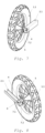
- Fig. 2 shows a perspective view of the pluggable wheel assembly in an advantageous embodiment of the invention.
- the release unit (not shown here) located at the end of the wheel side of the plug-in axle 3 is in a locked position.
- the wheel assembly has a profile strip 2.1, shown here in cross-section as a rectangular profile tube. This allows the interior of the illustrated profile strip 2.1 to be identified.
- the plug-in axle 3 can be pushed through the through opening (not shown here), which in this advantageous embodiment of the invention is formed at an outer end of the profile strip 2.1, and fastens the wheel 1.1 to the profile strip 2.1.
- curvatures 7.1 and 7.2 are each depicted as a countersink in the profile strip 2.1 and are formed concentrically on both sides of the profile strip 2.1 to the through opening (not shown here). In the advantageous embodiment of the invention shown, the curvatures 7.1 and 7.2 protrude into the interior of the profile strip 2.1.
- the curvatures 7.1 and 7.2 have a through-hole (not marked here) through which the plug-in axle 3 is inserted in this advantageous embodiment of the invention.
- the plug-in axle 3 does not protrude beyond the curvature 7.1, but is concealed within it.
- an additional countersink for each curvature 7.1 or 7.2 is shown, which is made, for example, with a countersink drill and has a larger diameter than the through hole (not marked here).
- the countersink is arranged concentrically to the through hole (not marked here).
- the curvatures 7.1 and 7.2 together with the locking unit 4 form a locking mechanism or are designed as a locking module.
- the locking unit 4 is shown, which is designed, for example, as a spring button or push button.
- the spacer sleeve or spacer bushing 5 is then placed on the curvature 7.2, which is located on the side of the profile strip 2.1 facing the wheel 1.1. This distances the wheel 1.1 from the profile strip 2.1 and/or the curvature 7.2, thus enabling free rotation of the wheel 1.1.
- the wheel 1.1 is connected to the thru axle 3 via a first bearing 9.1 and a second bearing (not shown here).
- the inner diameter of the first bearing 9.1 and the second bearing (not shown here) is almost equal to the outer diameter of the thru axle 3. Accordingly, a fit is formed which is either a clearance fit or an interference fit. Whether a clearance fit or an interference fit exists depends on the ratio of the respective inner diameter of the first bearing 9.1 or the second bearing (not shown here) and the outer diameter of the thru axle 3, whereby the more precise relationships are known to a person skilled in the art and are therefore not explained in more detail here.
- the wheel 1.1 is mounted on the quick-release axle 3 between the spacer bushing 5 and the hexagon nut (not shown here) on the contact surfaces of the first bearing 9.1 and the second bearing (not shown here), taking into account the longitudinal play of the wheel 1.1 relative to the spacer bushing 5 and/or the curvature 7.2 and/or the profile strip 2.1.
- an external thread (not shown here) is formed on the outer end of the quick-release axle 3 on the side of the quick-release axle 3 facing the wheel 1.1.
- This thread has a diameter that matches the internal thread of the hexagon nut (not shown here).
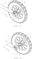
- Fig. 3 shows a perspective view of the pluggable wheel arrangement in an advantageous embodiment of the invention.
- the wheel 1.1, a spacer sleeve or spacer bushing 5 and the locking unit 4, which in this case is designed as a push button or spring button and is arranged on the plug-in axle 3, are arranged analogously to Fig. 2 visible.
- the profile strip 2.1 is depicted as a rectangular profile tube.
- the curvature 7.2 is shown protruding into the profile strip 2.1.
- the curvature 7.2, together with another curvature (not depicted here) and the locking unit 4, forms a locking mechanism so that the quick-release axle 3 is attached to the profile strip 2.1.
- the spacer sleeve 5 shown distances the profile strip 2.1 and/or the curvature 7.2 from the wheel 1.1.
- Fig. 4 shows a front view of the plug-in wheel arrangement in an advantageous embodiment of the invention.
- Fig. 2 discussed - the quick-release axle 3 on which the locking unit 4 is arranged, the wheel 1.1, the
- Fig. 5 shows a perspective view of the plug-in wheel arrangement in an advantageous embodiment of the invention. Analogous to Fig. 2 The plug-in axle 3, the locking unit 4 arranged on it, and the spacer sleeve or spacer bushing 5 are visible.
- the profile strip 2.1 is shown in section as a rectangular profile tube to better identify the bulges 7.1 and 7.2, which are arranged concentrically to the through opening (not shown here) and protrude into the profile strip 2.1.
- the wheel hub 20 and the wheel 1.1 are only partially shown in this figure.
- Fig. 6 shows a further front view of the plug-in wheel arrangement in an advantageous embodiment of the invention.
- the locking unit 4 which is arranged on the plug-in axle 3 and forms a locking mechanism with the curvatures 7.1 and 7.2, is shown, for example, as a spring button or push button.
- This locking mechanism enables the plug-in axle 3 to be attached to the profile strip 2.1, which is designed as a rectangular profile tube.
- the spacer sleeve or spacer bushing distances the profile strip 2.1 and/or the curvature 7.2, which already begins on the surface of the profile strip 2.1, from the wheel 1.1.
- the release unit 8 is shown, for example, in the form of a spring button or push button.
- Fig. 7 shows a perspective view of the pluggable wheel arrangement in an advantageous embodiment of the invention.
- the locking unit 4 which is arranged on the plug-in axle and forms a locking mechanism with the curvature 7.2 and another curvature (not shown here), and fastens the plug-in axle (not shown here) to the profile strip 2.1, shown as a spring button or push button.
- the profile strip 2.1 is shown as a rectangular profile tube into which the curvature 7.2 and another curvature (not shown here) protrude.
- the spacer sleeve or spacer bushing 5 distances the wheel 1.1 from the profile strip 2.1 and/or the curvature 7.2, which begins on the surface of the profile strip 2.1.
- Fig. 8 shows a perspective view of the pluggable wheel arrangement in an advantageous embodiment of the invention.
- the locking unit 4 which is arranged on the plug-in axle 3 and forms a locking mechanism with the curvatures 7.1 and 7.2, thus securing the plug-in axle 3 to the profile strip 2.1, shown as a spring button or push button, for example.
- the curvatures 7.1 and 7.2 protrude from the surface of the profile strip 2.1 into it.
- the profile strip 2.1 is shown in section as a rectangular profile tube to make the interior of the profile strip 2.1 more clearly visible.
- the wheel 1.1 mounted on the wheel hub (not shown here) is spaced from the profile strip 2.1 and/or the curvature 7.2 by the spacer sleeve or spacer bushing 5.
- Fig. 9 shows a perspective view of the pluggable wheel arrangement in an advantageous embodiment of the invention.
- the locking unit 4 which is arranged on the plug-in axle 3 and forms a locking mechanism with the curvatures 7.1 and 7.2, thus securing the plug-in axle 3 to the profile strip 2.1, is shown as a spring button or push button.
- the curvatures 7.1 and 7.2 protrude from the surface of the profile strip 2.1 into it.
- the profile strip 2.1 is shown in section as a rectangular profile tube to better illustrate the interior of the profile strip 2.1. recognizable.
- the wheel (not shown here) mounted on the wheel hub (not shown here) is spaced from the profile strip 2.1 and/or the curvature 7.2 by the spacer sleeve or spacer bushing 5.
- Fig. 10 shows a perspective view of the plug-in wheel assembly in an advantageous embodiment of the invention.
- the release unit 8, connected to the locking unit 4, is in a release position.
- the wheel assembly has a profile strip 2.1, which is shown here as a rectangular profile tube with a partial half-section. This allows the insertion area of the locking unit 4 and/or the release unit 8 to be identified in the interior of the illustrated profile strip 2.1.
- the plug-in axle 3 can be pushed through the through opening (not shown here), which in this advantageous embodiment of the invention is formed at an outer end of the profile strip 2.1, and fastens the wheel 1.1 to the profile strip 2.1.
- curvature 7.1 and another curvature are each depicted as a countersink in the profile strip 2.1 and are formed concentrically on both sides of the profile strip 2.1 relative to the through opening (not shown here).
- the curvature 7.1 and the other curvature do not protrude into the interior of the profile strip 2.1.
- the curvatures 7.1 and 7.2 have a through-opening (not shown here) through which the plug-in axle 3 is inserted in this advantageous embodiment of the invention.
- the plug-in axle 3 does not protrude beyond the curvature 7.1, but is concealed within it or in the profile strip 2.1.
- the spacer bushing 5 is then placed on the further curvature (not shown here), which is located on the side of the profile strip 2.1 facing the wheel 1.1. This spacer bushing separates the wheel 1.1 from the profile strip 2.1 and/or the further curvature (not shown here), allowing the wheel 1.1 to rotate freely.
- a double bore 11 is formed in the release unit 8.
- a double bore 11 is understood to be the combination of a smaller through-bore with a smaller bore diameter, which is arranged on the side of the double bore 11 facing the locking unit 4, and another through-bore whose bore diameter almost corresponds to the outer diameter of the thru axle 3.
- the smaller bore diameter corresponds almost to the outer diameter of the annular groove (not shown here) on the thru axle 3, whereby the annular groove (not shown here) is arranged on the side of the thru axle 3 facing away from the wheel 1.1 and the outer diameter of the annular groove (not shown here) is smaller than the outer diameter of the thru axle 3.
- a fit is formed accordingly, which is designed either as a clearance fit or as an interference fit.
- the locking unit 4 has, analogous to the profile strip 2.1, a further through-hole 10, with the aid of which a retaining pin (not shown here), which can be pushed through the further through-hole 10, mounts the locking unit 4 in the profile strip 2.1.
- the fit is either a clearance fit or a press fit. Whether a clearance fit or a press fit is present depends on the ratio of the diameter of the further Through opening 10 and the outer diameter of the retaining pin (not shown here), whereby the more precise relationships are known to a person skilled in the art and are therefore not explained in more detail here.
- the locking unit 4 and the release unit 8 are connected to one another via a connecting element (not shown here), which is designed, for example, as a spiral spring or helical spring.
- a connecting element (not shown here)
- the connecting element can be compressed and the release unit 8 can thus be transferred into a release position in which the plug-in spindle 3 can be pushed through the through-opening (not shown here) and the double bore 11.
- the release unit 8 returns to a locked position due to the resilient effect of the connecting element (not shown here). This prevents the plug-in spindle 3 from being separated from the profile strip 2.1, since the smaller bore and the outer surface of the annular groove (not shown here) are in operative contact, thus preventing movement of the plug-in spindle 3 in its longitudinal extent.
- the wheel 1.1 is connected to the thru axle 3 via a first bearing 9.1 and a second bearing (not shown here).
- the inner diameter of the first bearing 9.1 and the second bearing (not shown here) is almost equal to the outer diameter of the thru axle 3. Accordingly, a fit is formed which is either a clearance fit or an interference fit. Whether a clearance fit or an interference fit exists depends on the ratio of the respective inner diameter of the first bearing 9.1 or the second bearing (not shown here) and the outer diameter of the thru axle 3, whereby the more precise relationships are known to a person skilled in the art and are therefore not explained in more detail here.
- the wheel 1.1 is mounted on the quick-release axle 3 between the spacer bushing 5 and the hexagon nut (not shown here) on the contact surfaces of the first bearing 9.1 and the second bearing (not shown here), taking into account the longitudinal play of the wheel 1.1 relative to the spacer bushing 5 and/or the curvature 7.2 and/or the profile strip 2.1.
- an external thread (not shown here) is formed on the outer end of the quick-release axle 3 on the side of the quick-release axle 3 facing the wheel 1.1.
- This thread has a diameter that matches the internal thread of the hexagon nut (not shown here).
- Fig. 11 shows a perspective view of the plug-in wheel assembly in an advantageous embodiment of the invention.
- the release unit 8, which is connected to the locking unit 4, is in a locked position.
- the connecting element 12 is designed, for example, as a spiral spring or helical spring and is arranged between the locking unit 4 and the release unit 8.
- Fig. 10 The bearing 9.1, which is arranged on the plug-in axle 3, the profile strip 2.1, which is designed as a rectangular profile tube, and the additional through-hole 10, through which a retaining pin (not shown here) can be inserted in order to mount the locking unit 4 in the profile strip 2.1, are shown.
- the wheel 1.1 which is spaced from the profile strip 2.1 by the spacer sleeve or spacer bushing 5, is also visible.
- Fig. 12 shows a perspective view of the pluggable wheel arrangement in an advantageous embodiment of the invention.
- the wheel arrangement is connected to the locking unit 4 located release unit 8 analogous to Fig. 10 in a release position.
- the profile strip 2.1 which is shown by way of example as a rectangular profile tube with a half-section in the area of the locking unit 4 and the release unit 8, the bearing 9.1, which is arranged on the quick-release axle 3, and the further through-opening 10, through which a retaining pin (not shown here) can be pushed in order to mount the locking unit 4 in the profile strip 2.1, are shown.
- the plug-in wheel arrangement is in the middle of a switching process from a first plug-in position to a second plug-in position, whereby the plug-in wheel arrangement has not yet been transferred to the second plug-in position.
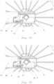
- Fig. 13 shows a perspective view of the plug-in wheel arrangement in an advantageous embodiment of the invention with a focus on the locking mechanism.
- the profile strip is not shown; instead, the illustration is limited to the locking unit 4, the connecting element 12, which is designed, for example, as a spiral spring or helical spring, the release unit 8 with the double bore 11, both of which are shown here in section, the plug-in axle 3 having the annular groove 13, the spacer sleeve or spacer bushing 5, the bearing 9.1, and the wheel hub 20.
- the release unit 8, which is connected to the locking unit 4, is in the release position here. It is also clearly visible that the connecting element 12 is compressed.
- the further through-opening 10 in the locking unit 4 is shown, which is located on the side of the locking unit 4 facing away from the connecting element 12 and through which a retaining pin (not shown) can be pushed in order to mount the locking unit 4 in the profile strip 2.1.
- Fig. 14 shows a perspective view of the plug-in wheel arrangement in an advantageous embodiment of the invention with a focus on the locking mechanism.
- the profile strip is not shown here, but the illustration is limited to the locking unit 4, the connecting element 12, which is designed, for example, as a spiral spring or helical spring, the release unit 8 with the double bore 11, both of which are shown here in section, the plug-in axle 3 having the annular groove 13, the spacer sleeve or spacer bushing 5, the bearing 9.1 and the wheel hub 20.
- the release unit 8, which is connected to the locking unit 4, is in the locked position here. It can also be clearly seen that the connecting element 12 is released and the smaller through-bore of the double bore 11 is in operative contact with the outer surface of the annular groove 13.
- the further through-opening 10 in the locking unit 4 is shown, which is located on the side of the locking unit 4 facing away from the connecting element 12 and through which a retaining pin (not shown) can be pushed in order to mount the locking unit 4 in the profile strip 2.1.
- Fig. 15 shows a perspective view of the plug-in wheel assembly in an advantageous embodiment of the invention, with a focus on the locking mechanism.
- the illustration is limited to the profile strip 2.1, which is shown, for example, as a rectangular profile tube with a half-section in the area of the locking unit 4 and the release unit 8, the locking unit 4, the connecting element 12, which is designed, for example, as a spiral spring or helical spring, the release unit 8 with the double bore 11, the plug-in axle 3, the spacer sleeve or spacer bushing 5, the bearing 9.1, and the wheel hub 20.
- the release unit 8, which is connected to the locking unit 4, is in the release position here. It is also clearly visible that the connecting element 12 is compressed.
- the further through-opening 10 in the locking unit 4 which is located on the side of the locking unit 4 facing away from the connecting element 12 and through which a retaining pin (not shown) can be pushed through in order to mount the locking unit 4 in the profile strip 2.1. It can also be seen that the plug-in axle 3 does not protrude laterally beyond the profile strip 2.1 and is thus hidden in this or the curvature (not shown here).
- Fig. 16 shows a perspective view of the plug-in wheel arrangement in an advantageous embodiment of the invention with a focus on the locking mechanism.
- the illustration is limited to the profile strip 2.1, which is shown by way of example as a rectangular profile tube with a half-section in the area of the locking unit 4 and the release unit 8, the locking unit 4, the connecting element 12, which is designed by way of example as a spiral spring or helical spring, the release unit 8 with the double bore 11, the plug-in axle 3, the spacer sleeve or spacer bushing 5, the bearing 9.1 and the wheel hub 20.
- the release unit 8, which is connected to the locking unit 4, is in the locked position here and the smaller through-bore of the double bore 11 is in operative contact with the outer surface of the annular groove (not shown here).
- the connecting element 12 is being released.
- the additional through-opening 10 in the locking unit 4 is shown. This opening is located on the side of the locking unit 4 facing away from the connecting element 12 and through which a retaining pin (not shown) can be inserted in order to mount the locking unit 4 in the profile strip 2.1. It can also be seen that the plug-in axle 3 does not protrude laterally beyond the profile strip 2.1 and is thus concealed in this or the curvature (not shown here).
- Fig. 17 shows a perspective view of the locking mechanism in an advantageous embodiment of the invention.
- the illustration focuses on the profile strip 2.1, which is shown as a rectangular profile tube with a half-section in the area of the locking unit 4 and the release unit 8, the locking unit 4, the connecting element 12, which is designed as a spiral spring or helical spring, and the Release unit 8 is limited by the double bore 11.
- the release unit 8, which is connected to the locking unit 4, is in the release position here. It is also clearly visible that the connecting element 12 is compressed.
- the additional through-opening 10 in the locking unit 4 is shown, through which a retaining pin (not shown) can be pushed in order to mount the locking unit 4 in the profile strip 2.1.
- the curvature 7.1 is concentric with the large bore of the double bore 11 in the release position.
- Fig. 18 shows a perspective view of the locking mechanism in an advantageous embodiment of the invention.
- the illustration is limited to the profile strip 2.1, which is shown by way of example as a rectangular profile tube with a half-section in the area of the locking unit 4 and the release unit 8, the locking unit 4, the connecting element 12, which is designed by way of example as a spiral spring or helical spring, and the release unit 8 with the double bore 11.
- the release unit 8, which is connected to the locking unit 4, is in the locked position here. It is also clearly visible that the connecting element 12 is being released.
- the further through-opening 10 in the locking unit 4 is shown, through which a retaining pin (not shown) can be pushed in order to mount the locking unit 4 in the profile strip 2.1.
- the curvature 7.1 is concentric with the small bore of the double bore 11 in the locked position.
- Fig. 19 shows a side view of the pluggable wheel assembly in an advantageous embodiment of the invention, with a focus on the locking mechanism.
- the profile strip 2.1 which is shown as an example as a rectangular profile tube with a partial section in the area of the locking unit 4 and the release unit 8, the locking unit 4, the release unit 8 with the double bore 11, the plug-in axle (not marked here), the curvature 7.1, and the wheel hub 20 are shown.
- the release unit 8, which is connected to the locking unit 4, is in the release position.
- the connecting element cannot be seen here.
- the additional through-opening 10 in the locking unit 4 and the profile strip 2.1 which is located on the side of the locking unit 4 facing away from the connecting element (not shown) and through which a retaining pin (not shown) can be pushed in order to mount the locking unit 4 in the profile strip 2.1. Also visible is the curvature (7.1) on the side of the profile strip 2.1, which, in the release position, is concentric with the large hole of the double hole 11.
- Fig. 20 shows a further side view of the plug-in wheel arrangement in an advantageous embodiment of the invention with a focus on the locking mechanism.
- the profile strip 2.1 which is shown by way of example as a rectangular profile tube with a partial section in the area of the locking unit 4 and the release unit 8, the locking unit 4, the release unit 8 with the double bore 11, the plug-in axle (not marked here), the bulge 7.1, which is located on the side of the profile strip 2.1, the connecting element 12, and the wheel hub 20 are shown.
- the release unit 8, which is connected to the locking unit 4, is here in a transitional position between the release position and the locked position.
- the connecting element 12 which is designed by way of example as a spiral spring or helical spring, can be partially seen because it is released and thus the bulge (7.1) is no longer concentric with the large bore of the double bore 11.
- the further through-opening 10 in the locking unit 4 and the profile strip 2.1 is shown, which is located on the side of the locking unit 4 facing away from the connecting element 12 and through which a retaining pin (not shown) can be pushed in order to mount the locking unit 4 in the profile strip 2.1.
- Fig. 21 shows a further side view of the pluggable wheel arrangement in an advantageous embodiment of the invention with a focus on the locking mechanism.
- the profile strip 2.1 which is shown as a rectangular profile tube with a partial section in the area of the locking unit 4 and the release unit 8, the locking unit 4, the release unit 8 with the double bore 11, the plug-in axle (not marked here), the curvature 7.1, which is located on the side of the profile strip 2.1, the connecting element 12 and the wheel hub 20 are shown.
- the release unit 8, which is connected to the locking unit 4, is in the locked position here.
- the connecting element 12 which is designed as a spiral spring or helical spring, for example, is clearly visible because it is relaxed and the smaller through-bore of the double bore 11 is therefore in operative contact with the outer surface of the annular groove (not shown here).
- the further through-opening 10 in the locking unit 4 and the profile strip 2.1 is shown, which is located on the side of the locking unit 4 facing away from the connecting element 12 and through which a retaining pin (not shown) can be pushed in order to mount the locking unit 4 in the profile strip 2.1.
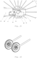
- Fig. 22 shows a perspective view of two pluggable wheel assemblies in the inner position in an advantageous embodiment of the invention. It can be seen that the use of the second plug-in position, also called the inner position, allows for a reduction in the track width, i.e., the distance between two adjacent wheels (not shown here). This allows for improved use of, for example, a rollator (not shown here) indoors.
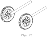
- Fig. 23 shows a perspective view of two pluggable wheel assemblies in the outer position in an advantageous embodiment of the invention. It can be seen that by using the first plug-in position, also called the outer position, an increase in the track width, i.e. the distance between two adjacent wheels (not shown here), is possible. This allows a higher The stability of a rollator (not shown here), for example, can be ensured when used in the field or on the road.
Landscapes
- Engineering & Computer Science (AREA)
- Mechanical Engineering (AREA)
- Health & Medical Sciences (AREA)
- Epidemiology (AREA)
- Pain & Pain Management (AREA)
- Physical Education & Sports Medicine (AREA)
- Rehabilitation Therapy (AREA)
- Life Sciences & Earth Sciences (AREA)
- Animal Behavior & Ethology (AREA)
- General Health & Medical Sciences (AREA)
- Public Health (AREA)
- Veterinary Medicine (AREA)
- Handcart (AREA)
- Coating Apparatus (AREA)
- Rolls And Other Rotary Bodies (AREA)
Abstract
Description
- Die vorliegende Erfindung betrifft eine steckbare Radanordnung, vorzugsweise zum Einsatz bei einem Rollator, mit den Merkmalen des Patentanspruches 1. Bei der Verwendung der Erfindung bei einem Rollator sind die einzelnen Räder umsteckbar, sodass die Spurbreite des Rollators veränderbar ist. Hierdurch lassen sich die Fahreigenschaften entsprechend der Umgebung, in welcher der Rollator eingesetzt werden soll, anpassen.
- Der Einsatz von Gehhilfen in Form von Rollatoren soll Menschen beim Gehen unterstützen, denen das Laufen ohne Gehhilfe sonst schwerfallen würde. Sie bieten diesen Menschen einen sicheren Halt und können gleichzeitig beim Gehen vor sich hergeschoben werden. Dabei ist ein besonders sicherer Stand der Rollatoren stets unbedingt erforderlich, da andernfalls Stürze mit auch schweren Verletzungen die Folge sein können. Besonders im Freien und bei unebenem Gelände muss ein sicherer Stand gewährleistet sein. Hierzu wird oftmals eine breite Spurweite gewählt, die ein seitliches Umkippen verhindert. Ist man jedoch in einer sehr ebenen Umgebung unterwegs, wie sie in Innenräumen vorzufinden ist, so kann ein Rollator schmaler ausgebildet werden, da dieser nicht »geländegängig« dimensioniert sein muss, um sicher bewegt werden zu können.
- Es gibt Rollatoren, die nur für Innenräume geeignet sind und dementsprechend eine schmalere Spurweite aufweisen als Rollatoren, die für draußen geeignet sind. Solche Rollatoren werden auch Indoor-Rollatoren genannt. Rollatoren für Innenräume sind nur für sehr ebene Umgebungen sicher. Die Breite ist hierbei so dimensioniert, dass die Rollatoren gut durch Innenräume bewegt werden können, ohne an Hindernisse wie Türen, Möbel und Wände zu stoßen. Eine schmale Bauweise hat hierbei den Vorteil, dass solche Rollatoren auch sehr wendig sind und durch schmale Lücken hindurchgeschoben werden können. Nachteilig ist jedoch, dass hierbei auch immer eine schmale Griffbreite einhergeht, die wiederum den Halt einer Person reduziert. Außerdem ist die Kippsicherheit durch die schmale Bauweise verringert. Für einen Einsatz draußen sind solche Indoor-Rollatoren gänzlich ungeeignet und stellen für den Benutzer ein erhebliches Sturzrisiko dar.
- Um sich draußen bei unebener Umgebung bewegen zu können, gibt es Rollatoren, die speziell für solche Bedingungen geschaffen sind, indem sie eine breitere Spurweite aufweisen als Rollatoren für Innenräume. Solche Rollatoren werden auch Outdoor-Rollatoren genannt. Durch die breitere Spurweite sind der Stand und dadurch auch der Halt stabiler. Sie weisen gegenüber Indoor-Rollatoren eine höhere Kippsicherheit auf. Auch kann so die Griffbreite entsprechend breiter gewählt werden, sodass sich Personen besser daran festhalten können. Nachteilig ist jedoch hierbei, dass auch das Handling und die Wendigkeit durch die breitere Bauweise verringert ist. Solche Rollatoren sind für den Gebrauch in Innenräumen gänzlich ungeeignet. Man würde schwerer durch Türen kommen und öfter an Hindernissen anstoßen, da Outdoor-Rollatoren breiter ausgebildet sind als Indoor-Rollatoren, da zumeist die Hinterräder bei Outdoor-Rollatoren außen angeordnet sind. Üblicherweise ist es nicht möglich die Vorderräder bei Rollatoren zu tauschen bzw. umzustecken.
- Sind Personen auf Rollatoren angewiesen und möchten sowohl drinnen in Innenräumen als auch draußen im Freien einen Rollator verwenden, so kommen sie nicht umhin, jeweils einen Rollator für draußen und einen Rollator für drinnen zu verwenden. Dies kostet zum einen Platz für die Rollatoren und zum anderen sind Rollatoren auch teuer in der Anschaffung. Darüber hinaus zahlt die gesetzliche Krankenkasse lediglich den günstigsten geeigneten Rollator oder aber auch nur einen Teil eines Rollators, sodass eine kostenintensive Zuzahlung erforderlich ist.
- Bei einer Erweiterung des betrachteten Stands der Technik im Hinblick auf Radanordnungen sind die im Folgenden aufgeführten Patentschriften zu nennen.
- Aus der
DE 1 865 003 U ist ein Kinderwagenrad mit Achsstummel und Kotschützer als abnehmbare Einheit offenbart. Dabei wird das Rad mithilfe einer beweglichen Nietverbindung und einem U-förmig gebogenen Flacheisen am Traggestell des Kinderwagens montiert. - Aus der
DE 10 2016 118 032 A1 sind eine Antriebseinheit und ein Rollstuhl mit Antriebseinheit bekannt, wobei die Montage des großen Rollstuhlrades an eine Antriebseinheit und damit an den Rollstuhl selbst aufgezeigt ist. Dabei wird eine Welle-Nabe-Verbindung genutzt, um die Ausgangswelle der Antriebseinheit mit der Antriebsachse des montierten Rades zu verbinden. - In
DE 20 308 860 U1 ist eine Montage einer Radeinheit eines Kinderwagens bekannt. Bei diesem Kinderwagen soll es möglich sein mittels der Vorderräder eine Lenkbewegungen zu möglichen. Dabei wird eine Radeinheit, bestehend aus einem Rad und einer an das Rad gekoppelten Radachse, in eine Radsitzeinheit montiert. - Es ist die Aufgabe der vorliegenden Erfindung eine steckbare Radanordnung, beispielsweise für einen Rollator, bereitzustellen. Eine solche steckbare Radanordnung erlaubt es, beispielsweise bei einem Rollator, die Spurbreite zu vergrößern oder zu verringern bzw. zu verkleinern, indem die Räder beidseitig an einer Profilleiste, beispielsweise des Rollators, montierbar, insbesondere einsteckbar, sind.
- Die Aufgabe wird durch die in Patentanspruch 1 angegebenen technischen Merkmale gelöst.
- Es ist eine steckbare Radanordnung vorgesehen. Die steckbare Radanordnung weist wenigstens ein Rad, wenigstens eine Profilleiste, wenigstens eine Steckachse und wenigstens eine Arretiereinheit auf, wobei das wenigstens eine Rad mit der wenigstens einen Steckachse verbindbar ausgebildet ist. Die wenigstens eine Profilleiste weist wenigstens eine Durchgangsöffnung senkrecht zur Mantelfläche und/oder Oberfläche der wenigstens einen Profilleiste auf. Die wenigstens eine Steckachse ist durch die wenigstens eine Durchgangsöffnung der wenigstens einen Profilleiste durchsteckbar ausgebildet, wobei die wenigstens eine Steckachse an der wenigstens einen Profilleiste von jeder Seite der wenigstens einen Profilleiste arretierbar ist. Die wenigstens eine Profilleiste weist wenigstens eine Wölbung auf, wobei die wenigstens eine Wölbung von der Oberfläche der wenigstens einen Profilleiste aus nach Innen und/oder Außen hineinragend und/oder herausragend ausgebildet ist, wobei die Wölbung konzentrisch zur Durchgangsöffnung ausgebildet ist.
- Unter der Angabe der Anzahl mit "wenigstens ein", ist entweder die Verwendung von genau einem Element oder zwei Elementen oder drei Elementen oder vier Elementen oder fünf Elementen oder einer anderen ganzzahligen Vielzahl an Elementen zu verstehen.
- Von jeder Seite der wenigstens einen Profilleiste arretierbar heißt, dass die wenigstens eine Steckachse sowohl von der einen Seite als auch von der anderen Seite an der wenigstens einen Profilleiste durchsteckbar und arretierbar ist. Gleiches gilt sodann auch für das wenigstens eine Rad, welches mit der wenigstens einen Steckachse verbindbar ist.
- Vorteilhaft kann ein Rollator aus vier erfindungsgemäßen, steckbaren Radanordnungen ausgebildet sein, wobei die entsprechenden Radanordnungen nach Patentanspruch 1 ausgebildet sind. Wenigstens zwei erfindungsgemäßen, steckbaren Radanordnungen sind im Wesentlichen paarweise nebeneinander angeordnet. Die so entstandenen Paare können hintereinander oder nebeneinander angeordnet sein.
- Vorteilhaft können die erfindungsgemäßen, steckbaren Radanordnungen durch Profilleisten miteinander verbindbar ausgebildet sein. Die Ausbildung von Verbindungen mit beispielsweise Stahlseilen oder ähnlichen Verbindungselemente ist ebenfalls möglich.
- Vorteilhaft kann wenigstens eine erfindungsgemäße, steckbare Radanordnung an wenigstens einer weiteren erfindungsgemäßen, steckbaren Radanordnung angeordnet sein. Kombinationen aus wenigstens zwei aneinander angeordneten erfindungsgemäßen, steckbaren Radanordnungen können im Wesentlichen nebeneinander oder hintereinander angeordnet sein. Die so entstandenen Kombinationen können hintereinander oder nebeneinander angeordnet sein.
- Vorteilhaft kann ein Rollator aus wenigstens zwei erfindungsgemäßen, steckbaren Radanordnungen ausgebildet sein. Die wenigstens zwei erfindungsgemäßen, steckbaren Radanordnungen sind im Wesentlichen paarweise nebeneinander angeordnet. Der Rollator weist eine Kombination aus wenigstens zwei weiteren Radanordnungen auf, die bereits eine kleinere Spurbreite ausbilden, damit der Betrieb im Innenraum möglich ist. Dabei ist die Spurbreite immer als Abstand zwischen wenigstens zwei Rädern definiert. Ob die Spurbreite vergrößert oder verringert wird, ist davon abhängig auf welcher Seite der wenigstens einen Profilleiste das wenigstens eine Rad gesteckt wird. Ist das wenigstens eine Rad in der ersten Steckposition, auch Außenposition genannt, angeordnet, ist eine vergrößerte Spurbreite ausgebildet. Ist das wenigstens eine Rad in der zweiten Steckposition, auch Innenposition genannt, angeordnet, ist eine verringerte Spurbreite ausgebildet
- Vorteilhaft ist das wenigstens eine Rad an einem freien Ende der wenigstens einen Profilleiste anordnenbar bzw. verbindbar. Dabei ist das wenigstens eine Rad vorteilhaft in beide Laufrichtungen ebenfalls drehbar. So kann die Radanordnung mit dem wenigstens einen Rad vorwärts und rückwärts bewegt werden. Das Rad bildet einen Freilauf aus.
- Das wenigstens eine Rad ist an einem freien Ende der wenigstens einen Steckachse anordnenbar bzw. verbindbar. Ist das wenigstens eine Rad mit der wenigstens einen Steckachse verbunden, so sind vorteilhaft das wenigstens eine Rad und die wenigstens eine Steckachse drehbar miteinander verbunden, sodass keine Drehbewegung von einer Komponenten auf die andere, das heißt von dem Rad auf die Steckachse und umgekehrt, übertragbar ist.
- Vorteilhaft ist das wenigstens eine Rad über wenigstens ein Lager mit der wenigstens einen Steckachse verbindbar. Das wenigstens eine Lager kann als Kugellager ausgebildet sein. Durch die Möglichkeit der steckbaren Anbringung der wenigstens einen Steckachse mit oder ohne des wenigstens einen Rads an die wenigstens eine Profilleiste ist die wenigstens eine Steckachse mit oder ohne dem wenigstens eine Rad leicht und schnell an die wenigstens eine Profilleiste montierbar. So kann sie zum Beispiel schnell und einfach gewechselt oder umgesteckt werden. Die wenigstens eine Arretiereinheit hält die wenigstens eine Steckachse nach der steckbaren Anbringung in ihrer Position an der wenigstens einen Profilleiste.
- Vorteilhaft ist der Innendurchmesser des wenigstens einen Lagers nahezu gleich zu dem Außendurchmesser der Steckachse ausgebildet. Es ist entsprechend eine Passung ausgebildet, die entweder als Spielpassung oder als Presspassung ausgebildet sein kann. Ob eine Spiel- oder eine Presspassung vorliegt, ist von dem Verhältnis des Innendurchmessers des Lagers und dem Außendurchmesser der Steckachse abhängig, wobei die genaueren Zusammenhänge einem Fachmann bekannt sind und diese hier aus diesem Grund nicht genauer ausgeführt werden.
- Vorteilhaft kann die wenigstens eine Wölbung als Erhöhung ausgebildet sein. Dabei folgt die Innenform der wenigstens einen Wölbung der Form der wenigstens einen Durchgangsöffnung. Damit kann die Kraftverteilung auf die wenigstens eine Steckachse, die durch die wenigstens eine Durchgangsöffnung durchsteckbar ausgebildet ist, durch die größere Auflagefläche besser verteilt werden. Zusätzlich kann die wenigstens eine Steckachse länger ausgebildet sein. Zusätzlich kann die wenigstens eine Steckachse derart ausgebildet sein, dass sie nicht über die wenigstens eine Wölbung auf jeder Seite der wenigstens einen Profilleiste seitlich übersteht. Damit ist auch eine schutzgeschützte Montage der wenigstens einen Steckachse in der wenigstens einen Profilleiste möglich.
- Vorteilhaft kann die wenigstens eine Wölbung als Senkung ausgebildet sein. Dabei folgt die Innenform der wenigstens einen Wölbung der Form der wenigstens einen Durchgangsöffnung. Damit kann die Kraftverteilung auf die wenigstens eine Steckachse, die durch die wenigstens eine Durchgangsöffnung durchsteckbar ausgebildet ist, durch die größere Auflagefläche besser verteilt werden. Zusätzlich kann die wenigstens eine Steckachse kürzer ausgebildet sein. Zusätzlich kann die wenigstens eine Steckachse derart ausgebildet sein, dass sie nicht über die wenigstens eine Profilleiste seitlich übersteht. Damit ist auch eine schutzgeschützte Montage der wenigstens einen Steckachse in der wenigstens einen Profilleiste möglich.
- Es ist sicherzustellen, dass die wenigstens eine Steckachse durch die wenigstens eine Durchgangsöffnung und die wenigstens eine Wölbung steckbar ist. Zudem dürfen keine Probleme bedingt durch die gewählten Formen der wenigstens einen Durchgangsöffnung und der wenigstens einen Steckachse entstehen, wie sie beispielsweise bei der Montage des wenigstens einen Rads auf der wenigstens einen Steckachse auftreten könnten.
- Vorteilhaft kann die äußere Form der wenigstens einen Wölbung kreisförmig oder oval oder polygonförmig oder sternförmig ausgebildet sein. Vorteilhaft ist die äußere Form der wenigstens einen Wölbung als Kombination aus wenigstens einer Teilform ausgebildet, wobei die wenigstens eine Teilform kreisförmig oder oval oder polygonförmig oder sternförmig ausgebildet sein kann.
- Vorteilhaft kann die wenigstens eine Profilleiste kreisförmig oder oval oder elliptisch oder polygonförmig oder sternförmig, vorteilhafter kreisförmig oder oval oder elliptisch oder polygonförmig ausgebildet sein.
- Vorteilhaft kann die Profilleiste aus Kunststoff oder auch faserverstärktem Kunststoff oder Metall oder Carbon gefertigt sein.
- Vorteilhaft kann die wenigstens eine Profilleiste als Profilrohr ausgebildet sein.
- Vorteilhaft kann die wenigstens eine Profilleiste wenigstens eine Führungsrille an wenigstens einer Seite der wenigstens einen Profilleiste aufweisen. Vorteilhaft kann die wenigstens eine Führungsrille als Aufschiebeführung ausgebildet sein. Mit der wenigstens einen Führungsrille kann beispielsweise wenigstens eine Schützhülle oder Schutzprofil montiert werden.
- Vorteilhaft kann das wenigstens eine Rad in seiner Größe variabel ausgebildet sein. Sind mehrere Räder vorhanden, dann sind wenigstens nebeneinanderliegende Räder in ihrer Größe im Wesentlichen gleich ausgebildet.
- Vorteilhaft kann das wenigstens eine Rad in seinem Profil variabel ausgebildet sein. Sind mehrere Räder vorhanden, dann sind wenigstens nebeneinanderliegende Räder ihr Profil betreffend im Wesentlichen gleich ausgebildet.
- In einer weiteren vorteilhaften Ausgestaltung der Erfindung kann die wenigstens eine Steckachse kreisförmig oder oval oder elliptisch oder polygonförmig oder sternförmig, vorteilhafter kreisförmig oder oval oder elliptisch oder polygonförmig ausgebildet sein.
- Vorteilhaft ist die wenigstens eine Steckachse im Radbereich kreisförmig ausgebildet. Damit kann eine einfache Montage der Lager sowie das Aufbringen eines Außengewindes ermöglicht werden.
- Weiterhin ist vorteilhaft die Durchgangsöffnung mit Hilfe einer Form gestanzt oder geschnitten, beispielsweise mit einem Laser- oder Wasserstrahlschneidegerät oder gebohrt und/oder anschließend entgratet ausgebildet.
- Vorteilhaft kann die wenigstens eine Durchgangsöffnung kreisförmig oder oval oder elliptisch oder polygonförmig oder sternförmig ausgebildet sein.
- Vorteilhaft sind die Formen der wenigstens einen Steckachse und der wenigstens einen Durchgangsöffnung gleich ausgebildet.
- Vorteilhaft weisen die Abmessungen der Querschnitte der wenigstens einen Steckachse und der wenigstens einen Durchgangöffnung einen ähnlichen Wert auf. Dabei entspricht der Querschnitt der wenigstens einen Steckachse der Fläche, die senkrecht zur Längsrichtung der Steckachse angeordnet ist.
- Noch vorteilhafter bilden die Abmessungen der Querschnitte der wenigstens einen Steckachse und der wenigstens einen Durchgangsöffnung eine Spielpassung aus. Das bedeutet, dass der Durchmesser der wenigstens einen Durchgangsöffnung so groß ist, dass die wenigstens eine Steckachse hindurchgesteckt werden kann. Dabei entspricht der Außendurchmesser der wenigstens einen Steckachse im Wesentlichen dem Durchmesser der wenigstens einen Durchgangsöffnung, wobei im Wesentlichen bedeutet, dass zwischen diesen eine Passtoleranz vorgesehen ist, so wie sie für die Dimensionierung von Spielpassungen fachüblich ist. In diesem Fall kann dies je nach Größe des Außendurchmessers der Steckachse wenige Hundertstelmillimeter bis Zehntelmillimeter betragen.
- Vorteilhafte Weiterbildungen finden sich in den Unteransprüchen.
- In einer vorteilhaften Ausgestaltung der Erfindung nach Patentanspruch 2 ist vorgesehen, dass wenigstens eine Wölbung an der wenigstens einen Profilleiste auf jeder Seite der wenigstens einen Durchgangsöffnung der wenigstens einen Profilleiste angeordnet ist. Damit kann die wenigstens eine Steckachse von beiden Seiten der wenigstens einen Profilleiste derart in die wenigstens eine Profilleiste und die wenigstens eine Wölbung eingesteckt werden, dass die wenigstens eine Steckachse seitlich nicht über die wenigstens eine Profilleiste und/oder die wenigstens eine Wölbung übersteht.
- In einer vorteilhaften Ausgestaltung der Erfindung nach Patentanspruch 3 ist vorgesehen, dass das wenigstens eine Rad mit der wenigstens einen Steckachse von jeder Seite der Profilleiste in die jeweils wenigstens eine Durchgangsöffnung der wenigstens einen Profilleiste und/oder der wenigstens einen Wölbung einsteckbar ist, wodurch das wenigstens eine Rad in eine erste Steckposition und eine zweite Steckposition verbringbar ist. Dabei ist die erste Steckposition, auch Außenposition genannt, dadurch gekennzeichnet, dass das wenigstens eine Rad außen an der wenigstens einen Profilleiste angeordnet ist. Die zweite Steckposition, auch Innenposition genannt, ist dagegen dadurch gekennzeichnet, dass das wenigstens eine Rad innen an der wenigstens einen Profilleiste angeordnet ist.
- In einer vorteilhaften Ausgestaltung der Erfindung nach Patentanspruch 4 ist vorgesehen, dass eine Veränderung der Spurbreite durch ein Umstecken des wenigstens einen Rads von einer ersten Steckposition in eine zweite Steckposition und/oder umgekehrt bewirkbar ist und/oder wenigstens ein Anschlag auf der dem wenigstens einen Rad zugewandten Seite der wenigstens einen Steckachse angeordnet ist, wobei der wenigstens eine Anschlag das wenigstens eine Rad von der wenigstens einen Wölbung und/oder der wenigstens einen Profilleiste beabstandet und/oder der wenigstens eine Anschlag derart ausgebildet ist, dass die wenigstens eine Steckachse in jeder Steckposition seitlich der Profilleiste und/oder Wölbung nicht übersteht.
- Dabei ist die erste Steckposition, auch Außenposition genannt, dadurch gekennzeichnet, dass das wenigstens eine Rad außen an der wenigstens einen Profilleiste angeordnet ist. Die zweite Steckposition, auch Innenposition genannt, ist dagegen dadurch gekennzeichnet, dass das wenigstens eine Rad innen an der wenigstens einen Profilleiste angeordnet ist.
- Werden auf beiden Seiten eines Rollators die Räder entsprechend in ihrer Steckposition um ca. 180° verlagert bzw. umgesteckt, das heißt zum Beispiel von einer Innenposition in eine Außenposition überführt, so wird der Abstand der Räder um insgesamt ca. 180 mm vergrößert. Man spricht in diesem Fall von einer Spurbreitenvergrößerung um ca. 180 mm, was einen deutlich stabileren und sicheren Stand des Rollators ermöglicht, sodass dieser im Außenbereich eingesetzt werden kann.
- Werden die Räder jeweils in eine Innenposition überführt, so wird insgesamt die Spurbreite um ca. 180 mm verringert, was den Einsatz in engen Innenräumen deutlich erleichtert. Gleichzeitig können sich die Räder durch ihre innenliegenden Position nicht mit beispielsweise Türkanten oder Möbelkanten verhaken. Bei einer möglichen Kollision des Rollators mit Hindernissen berühren sich lediglich die Profilrohre mit der Schutzleiste, wodurch der Zusammenstoß abgefedert und abgeleitet wird. Dies erhöht zusätzlich die Sicherheit des Rollators in Innenräumen.
- Vorteilhaft ist der wenigstens eine Anschlag, welcher auf der Steckachse angeordnet ist, fest oder vorteilhafter demontierbar mit der Steckachse verbindbar. Ist der wenigstens eine Anschlag, beispielsweise in Form einer Distanzbuchse, demontierbar mit der wenigstens einen Steckachse verbunden, also beispielsweise angeschraubt oder gesteckt oder verpresst, kann bei beispielsweise Versagen oder Verschleiß des wenigstens einen Anschlags, dieser jederzeit ohne großen Aufwand oder große Kosten ausgetauscht werden. Analog ist bei Versagen oder Verschleiß die wenigstens eine Steckachse jederzeit ohne großen Aufwand oder große Kosten austauschbar.
- Vorteilhaft ist dadurch, dass der wenigstens ein Anschlag auf der dem wenigstens einen Rad zugewandten Seite der wenigstens einen Steckachse angeordnet ist, wobei der wenigstens eine Anschlag das wenigstens eine Rad von der wenigstens einen Wölbung und/oder der wenigstens einen Profilleiste beabstandet, das wenigstens eine Rad stets so montierbar, dass ein freier Lauf des wenigstens einen Rads gewährleistet werden kann. Das bedeutet, dass durch die Beabstandung sichergestellt wird, dass die Bewegung des wenigstens einen Rads nicht durch andere Komponenten der Radanordnung beeinträchtigt wird. Davon ist eine mögliche Bremseinrichtung ausgenommen.
- Je nach Länge der wenigstens einen Steckachse und der Positionierung des wenigstens einen Anschlags auf der wenigstens einen Steckachse kann diese so ausgebildet sein, dass die wenigstens eine Steckachse seitlich nicht über die wenigstens eine Profilleiste und die wenigstens eine Wölbung übersteht.
- Vorteilhaft ist an der wenigstens einen Steckachse wenigstens ein Anschlag angeordnet. Besonders vorteilhaft ist der wenigstens eine Anschlag auf der dem wenigstens einen Rad zugewandten Seite der wenigstens einen Steckachse angeordnet. Mit Hilfe des wenigstens einen Anschlags kann das wenigstens eine Rad von der wenigstens einen Wölbung und/oder der wenigstens einen Profilleiste beabstandet werden. Damit ist es möglich eine freie Rotation des wenigstens einen Rads zu gewährleisten.
- Vorteilhaft kann der wenigstens eine Anschlag als Distanzbuchse oder Distanzhülse ausgebildet sein.
- Vorteilhaft ist der wenigstens eine Anschlag, beispielsweise in Form einer Distanzbuchse, durch einen Bediener lösbar ausgebildet. Das Lösen des Anschlags kann vorteilhaft beispielsweise durch die Integration einer Löseeinheit durchführbar sein. Diese Löseeinheit kann beispielsweise als Federknopf und/oder Druckknopf ausgebildet sein. Weiterhin kann die Löseeinheit beispielsweise auf der Radseite angeordnet sein.
- Vorteilhaft ist der Anschlag in seinem Querschnitt zumindest teilweise polygonförmig oder elliptisch oder kreisförmig oder sternförmig ausgebildet.
- Vorteilhaft ist der wenigstens eine Anschlag, beispielhaft in Form einer Distanzbuchse, der auf dem wenigstens einen Rad abgewandten Seite der wenigstens einen Profilleiste angeordnet ist, auf die wenigstens eine Wölbung formschlüssig aufschiebbar ausgebildet.
- Vorteilhaft weist der wenigstens eine Anschlag, beispielhaft in Form einer Distanzbuchse, der auf dem wenigstens einen Rad abgewandten Seite der wenigstens einen Profilleiste angeordnet ist, wenigstens eine Ausnehmung auf mit der die äußere Mantelfläche der wenigstens einen Wölbung eine Spielpassung ausbildet ausgebildet.
- Vorteilhaft liegt der wenigstens eine Anschlag in der eingesteckten Form der wenigstens einen Steckachse an der Mantelfläche der wenigstens einen Profilleiste an.
- Vorteilhaft kann der wenigstens eine Anschlag, beispielsweise in Form einer Distanzhülse, formschlüssig auf die wenigstens eine Wölbung aufgesteckt werden. Zusätzlich kann dadurch sichergestellt werden, dass der wenigstens eine Anschlag kein Klappergeräusch oder ein anderes störendes Geräusch während einer Benutzung der wenigstens einen steckbaren Radanordnung erzeugt.
- Vorteilhaft ist die Verbindung der wenigstens einen Wölbung mit dem wenigstens einen Anschlag als Spielpassung ausgebildet. Damit sind geringfügige Fertigungstoleranzen des wenigstens einen Anschlags oder der wenigstens einen Wölbung ausgleichbar. Besonders bei einem Austausch des wenigstens einen Anschlags bedingt durch beispielsweise Verschleiß oder Beschädigung ist das vorteilhaft, da so Kosten und Fertigungsaufwand eingespart werden können.
- In einer weiteren vorteilhaften Ausgestaltung der Erfindung ist vorgesehen, dass mit wenigstens einem Klemmring das wenigstens eine Rad auf der wenigstens einen Steckachse zwischen dem wenigstens einen Anschlag, der beispielhaft als Distanzbuchse ausgebildet sein kann, und dem wenigstens einen Klemmring an den Auflageflächen der beispielsweise wenigstens zwei Lager unter Berücksichtigung eines Längsspiels montierbar ausgebildet.
- Vorteilhaft ist am äußeren Ende der wenigstens einen Steckachse der dem wenigstens einen Rad zugewandten Seite der wenigstens einen Steckachse ein Außengewinde ausgebildet. Vorteilhaft weist dieses Außengewinde einen zu dem Innengewinde des wenigstens einen Klemmrings passenden Durchmesser auf. Damit ist eine sichere Montage des wenigstens einen Rads auf der wenigstens einen Steckachse möglich.
- Vorteilhaft kann das Längsspiel des wenigstens einen Rads auf der wenigstens einen Steckachse, das zwischen dem wenigstens einen Anschlag und dem wenigstens einen Klemmring platziert ist, durch die Platzierung des wenigstens einen Klemmrings auf dem Außengewinde der wenigstens Steckachse einstellbar ausgebildet sein.
- Vorteilhaft ist mit wenigstens einem Klemmring das wenigstens eine Rad auf der wenigstens einen Steckachse zwischen dem wenigstens einen Profilrohr, vorteilhafter der wenigstens einen Wölbung und dem wenigstens einen Klemmring an den Auflageflächen der beispielsweise wenigstens zwei Lager unter Berücksichtigung eines Längsspiels montierbar ausgebildet.
- Vorteilhaft kann das Längsspiel des wenigstens einen Rads auf der wenigstens einen Steckachse, das zwischen dem wenigstens einen Profilrohr, vorteilhafter der wenigstens einen Wölbung und dem wenigstens einen Klemmring platziert ist, durch die Platzierung des wenigstens einen Klemmrings auf dem Außengewinde der wenigstens Steckachse einstellbar ausgebildet sein.
- Vorteilhaft kann der wenigstens eine Klemmring als Sechskantmutter ausgebildet sein.
- In einer vorteilhaften Ausgestaltung der Erfindung nach Patentanspruch 5 ist vorgesehen, dass die wenigstens eine Profilleiste als Profilrohr oder als mit einem Gitter gefüllte Stange ausgebildet ist.
- Vorteilhaft ist das wenigstens eine Profilrohr und/oder die wenigstens eine mit einem Gitter gefüllte Stange kreisförmig oder oval oder elliptisch oder polygonförmig oder sternförmig, vorteilhafter kreisförmig oder oval oder elliptisch oder polygonförmig ausgebildet.
- Vorteilhaft weist das Gitter, mit dem die wenigstens eine mit einem Gitter gefüllte Stange ausgebildet ist, einen polygonförmigen oder elliptischen oder kreisförmigen oder sternförmigen Querschnitt auf. Wiederum vorteilhaft weist das Gitter, mit dem die wenigstens eine mit einem Gitter gefüllte Stange ausgebildet ist, eine dreidimensionale Lattice-Struktur auf, wie beispielsweise eine Weaire-Phelan- oder Honeycomp-Struktur. Dies ist nicht einschränkend zu verstehen, da auch weitere dem Fachmann bekannten, dreidimensionalen Lattice-Strukturen verwendbar sind.
- In einer vorteilhaften Ausgestaltung der Erfindung nach Patentanspruch 6 ist vorgesehen, die wenigstens eine Wölbung und die wenigstens eine Arretiereinheit eine Arretierung ausbilden und/oder als Arretiermodul ausgebildet sind.
- Durch die Ausbildung der Arretierung und/oder des Arretiermoduls durch die wenigstens eine Wölbung und die wenigstens eine Arretiereinheit wird eine besonders gute Handhabbarkeit erreicht, wobei auch die Austauschbarkeit einzelner Komponenten erleichtert wird. Ist die Arretiereinheit beispielsweise verschlissen, kann diese ausgetauscht werden, ohne die gesamte Arretierung und/oder das gesamte Arretiermodul zu ersetzen. Das ist nachhaltig und spart Kosten.
- Vorteilhaft kann die wenigstens eine Arretiereinheit in Form von wenigstens einem Federknopf und/oder wenigstens einem Druckknopf oder wenigstens einem Haltebügel oder wenigstens einer Kombination aus einer Feder und einem Stift oder weiteren dem Fachmann bekannten federbasierten oder auf federähnlichen Aufbauten basierende Vorrichtungen ausgebildet sein.
- In einer vorteilhaften Ausgestaltung der Erfindung nach Patentanspruch 7 ist vorgesehen, dass die wenigstens eine Arretiereinheit auf der dem Rad abgewandten Seite der Steckachse angeordnet ist. Die wenigstens eine Arretiereinheit befindet sich entsprechend an einem freien Ende der wenigstens einen Steckachse. Damit ist die wenigstens eine Steckachse mit der Seite an der die wenigstens eine Arretiereinheit angeordnet ist durch die wenigstens eine Durchgangsöffnung der jeweils wenigstens einen Profilleiste und der wenigstens einen Wölbung durchsteckbar. Dabei kann in Abhängigkeit der Länge der wenigstens einen Steckachse und der Positionierung der wenigstens einen Arretiereinheit auf der wenigstens einen Steckachse das wenigstens eine Arretiermodul bestehend aus der wenigstens einen Arretiereinheit und der wenigstens einen Profilleiste, vorteilhafter der wenigstens einen Wölbung so ausgebildet sein, dass die wenigstens eine Steckachse seitlich nicht über die wenigstens eine Profilleiste und/oder die wenigstens eine Wölbung übersteht.
- In einer vorteilhaften Ausgestaltung der Erfindung nach Patentanspruch 8 ist vorgesehen, dass die wenigstens eine Wölbung je Seite der wenigstens einen Profilleiste wenigstens eine der Form der wenigstens einen Arretiereinheit entsprechende umlaufende Ringnut im Inneren der wenigstens einen Profilleiste ausbilden und/oder die wenigstens eine Wölbung je Seite der wenigstens einen Profilleiste wenigstens eine der Form der wenigstens einen Arretiereinheit entsprechende umlaufende Ringnut in der inneren und/oder äußeren Mantelfläche der wenigstens einen Wölbung aufweist.
- Bilden die wenigstens eine Wölbung je Seite der wenigstens einen Profilleiste wenigstens eine der Form der wenigstens einen Arretiereinheit entsprechende umlaufende Ringnut im Inneren der wenigstens einen Profilleiste, kann die wenigstens eine Arretierung und/oder das wenigstens eine Arretiermodul bestehend aus der wenigstens einen Wölbung und der wenigstens einen Arretiereinheit durch die Platzierung des wenigstens einen Verschlussmechanismus innerhalb der wenigstens einen Profilleiste nicht sichtbar und/oder schmutzgeschützt ausgebildet ist. Dabei entspricht die umlaufende Ringnut einem Ringförmigen Hohlraum zwischen den beiden Wölbungen.
- Vorteilhaft weist die wenigstens eine Wölbung je Seite der wenigstens einen Profilleiste wenigstens eine der Form der wenigstens einen Arretiereinheit entsprechende umlaufende Ringnut in der inneren und/oder äußeren Mantelfläche der wenigstens einen Wölbung auf. Das bedeutet, dass die wenigstens eine Arretierung und/oder das wenigstens eine Arretiermodul bestehend aus der wenigstens einen Wölbung und der wenigstens einen Arretiereinheit durch die Platzierung des wenigstens einen Verschlussmechanismus innerhalb der wenigstens einen Wölbung bzw. der wenigstens einen Profilleiste nicht sichtbar und/oder schmutzgeschützt ausgebildet ist.
- In den genannten vorteilhaften Ausführungsformen der wenigstens einen Arretierung und/oder des wenigstens einen Arretiermoduls entspricht das Außenmaß der wenigstens einen Arretiereinheit im Wesentlichen den Abmessungen der wenigstens einen Ringnut, wobei im Wesentlichen bedeutet, dass zwischen diesen eine Passtoleranz vorgesehen ist, so wie sie für die Dimensionierung von Spielpassungen fachüblich ist. In diesem Fall kann dies je nach Größe des Außenmaßes der Arretiereinheit wenige Hundertstelmillimeter bis Zehntelmillimeter betragen. Damit können Fertigungsabweichungen einfach ausgeglichen werden.
- In einer vorteilhaften Ausgestaltung der Erfindung nach Patentanspruch 9 ist vorgesehen, dass die wenigstens eine Arretiereinheit als Einsatz in die wenigstens eine Profilleiste einschiebbar und/oder einsetzbar ausgebildet ist und/oder die wenigstens eine Arretiereinheit über wenigstens ein Verbindungselement mit der wenigstens einen Löseeinheit verbindbar ausgebildet ist und/oder die wenigstens eine Arretiereinheit gemeinsam mit dem wenigstens einen Verbindungselement und der wenigstens einen Löseeinheit wenigstens eine Arretierung und/oder als wenigstens ein Arretiermodul ausgebildet sind und/oder die wenigstens eine Löseeinheit wenigstens eine Durchgangsbohrung aufweist, wobei die wenigstens eine Durchgangsbohrung als Doppelbohrung mit zwei sich unterscheidenden Durchmessern ausgebildet ist.
- Dabei entspricht die Form der wenigstens einen Arretiereinheit in ihrer Längserstreckung der Form der inneren Aushöhlung der wenigstens einen Profilleiste in ihrer Längserstreckung. Vorteilhaft wird somit eine Passung ausgebildet. Besonders vorteilhaft wird eine Spielpassung ausgebildet. Damit kann die wenigstens eine Arretiereinheit möglichst einfach innerhalb der wenigstens einen Profilleiste verschoben werden.
- Das wenigstens eine Verbindungselement ist vorteilhaft als Federelement ausgebildet. Beispielhaft kann das Federelement als Spiralfeder oder als Schraubenfeder ausgebildet sein. Vorteilhaft erlaubt das wenigstens eine Verbindungselement die Bewegung der wenigstens einen Löseeinheit gegenüber der wenigstens einen Arretiereinheit in der Längserstreckung der wenigstens einen Profilleiste. Besonders vorteilhaft überführt das wenigstens eine Verbindungselement die wenigstens eine Löseeinheit von einer ersten Schiebeposition, auch Entriegelungsposition genannt, in eine zweite Position, auch Verriegelungsposition genannt. Die Überführung der wenigstens einen Löseeinheit in die zweite Schiebeposition erfolgt besonders vorteilhaft von selbst. Die wenigstens eine Arretierung und/oder das wenigstens eine Arretiermodul bestehend aus wenigstens einer Arretiereinheit und wenigstens einem Verbindungselement und wenigstens einer Löseeinheit ist also selbstarretierend ausgebildet.
- Der größere Durchmesser der Doppelbohrung ist vorteilhaft derart ausgebildet, dass die Steckachse hindurch steckbar ist. Der kleinere Durchmesser ist dagegen vorteilhaft so bemessen, dass ein Durchstecken der Steckachse verhindert wird. Die unterschiedlich großen Durchmesser der Doppelbohrungen überschneiden sich derart, dass die kleinere Bohrung an ihrer breitesten Stelle, die gleichzeitig dem kleineren Durchmesser entspricht, in die größere Bohrung mit dem größeren Durchmesser übergeht.
- In einer vorteilhaften Ausgestaltung der Erfindung nach Patentanspruch 10 ist vorgesehen, dass die wenigstens eine Steckachse eine umlaufende Ringnut aufweist.
- In einer weiteren vorteilhaften Ausführungsform weist die wenigstens eine Steckachse beidseitig entlang ihrer Längserstreckung jeweils eine Ringnut auf, sodass die wenigstens eine Steckachse insgesamt zwei Ringnuten aufweist.
- Vorteilhaft ist der Durchmesser der Mantelfläche der wenigstens einen Ringnut kleiner als der der Außendurchmesser der wenigstens einen Steckachse ausgebildet.
- Dabei dient die wenigstens eine Ringnut dazu, die wenigstens eine Steckachse mit Hilfe der wenigstens einen Löseeinheit und der wenigstens einen Durchgangsöffnung der wenigstens einen Profilleiste zu fixieren. Dabei wird die wenigstens eine Doppelbohrung der wenigstens einen Löseeinheit genutzt, um die wenigstens eine Steckachse senkrecht zur Mantelfläche und/oder Oberfläche der wenigstens einen Profilleiste in Position zu halten. Vorteilhaft wird eine Passung zwischen dem ersten bzw. kleinen Durchmesser der wenigstens einen Doppelbohrung und der Mantelfläche der wenigstens einen Ringnut der wenigstens einen Steckachse ausgebildet. Vorteilhafter wird eine Spielpassung ausgebildet.
- Vorteilhaft bilden der Außendurchmesser der wenigstens einen Steckachse und die wenigstens eine Durchgangsöffnung der wenigstens einen Profilleiste ebenfalls eine Passung aus. Dabei ist es erneut von Vorteil, wenn eine Spielpassung ausgebildet wird.
- Vorteilhaft betragen die Toleranzen der beide erläuterten Spielpassungen je nach Größe des Außenmaßes der der wenigstens einen Ringnut und/oder des Außendurchmessers der wenigstens einen Steckachse wenige Hundertstelmillimeter bis Zehntelmillimeter. Damit können Fertigungsabweichungen einfach ausgeglichen werden.
- Vorteilhaft weist die Ringnut ein rechteckiges Rotationsprofil auf, wobei das rechteckige Rotationsprofil um die Rotationsachse, welche entlang der Längserstreckung der Steckachse verläuft, rotiert ist. Es ist aber auch alternativ denkbar, dass die Ringnut ein rundes, insbesondere ein halbkreisförmiges oder U-förmiges Rotationsprofil, oder ein V-förmiges Rotationsprofil aufweist.
- In einer vorteilhaften Ausgestaltung der Erfindung nach Patentanspruch 11 ist vorgesehen, dass bei der wenigstens einen Doppelbohrung ein erster und ein zweiter Durchmesser vorgesehen sind, wobei der erste Durchmesser dem Außendurchmesser der wenigstens einen Ringnut der wenigstens einen Steckachse und der zweite Durchmesser dem Außendurchmesser der wenigstens einen Steckachse derart entspricht, dass die Durchmesser der Doppelbohrung und die jeweiligen Außendurchmesser der wenigstens einen Ringnut und der wenigstens einen Steckachse jeweils als Passung ausgebildet sind.
- Das heißt, dass der erste Durchmesser so groß ist, dass die Steckachse hindurchgesteckt werden kann. Dabei entspricht der zweite Durchmesser im Wesentlichen dem Außendurchmesser der Steckachse, wobei im Wesentlichen bedeutet, dass zwischen diesen eine Passtoleranz vorgesehen ist, so wie sie für die Dimensionierung von Spielpassungen fachüblich ist. In diesem Fall kann dies je nach Größe des Außendurchmessers der Steckachse wenige Hunderstelmillimeter bis Zehntelmillimeter betragen. Gleiches gilt ebenfalls für das Verhältnis zwischen ersten Durchmesser und Außendurchmesser der Ringnut. Die Bohrung in dem wenigstens einen Profilrohr bildet ebenfalls mit dem Außendurchmesser der Steckachse eine Spielpassung aus.
- In einer vorteilhaften Ausgestaltung der Erfindung nach Patentanspruch 12 ist vorgesehen, dass die wenigstens eine Löseeinheit wenigstens eine Senkung auf jeder Seite der wenigstens einen Löseeinheit aufweist, wobei die Form der wenigstens einen Senkung der Form der wenigstens einen Doppelbohrung folgend ausgebildet ist. Damit können scharfe Kanten vermieden werden. Zudem wird ein Einrasten der wenigstens einen Steckachse in die wenigstens eine Doppelbohrung der wenigstens einen Löseeinheit erleichtert.
- In einer vorteilhaften Ausgestaltung der Erfindung nach Patentanspruch 13 ist vorgesehen, dass die wenigstens eine Profilleiste und die wenigstens eine Arretiereinheit wenigstens eine weitere Durchgangsöffnung aufweisen, wobei wenigstens ein Halteelement durch die wenigstens eine weitere Durchgangsöffnung der wenigstens einen Profilleiste und der wenigstens einen Arretiereinheit durchsteckbar ausgebildet ist.
- Vorteilhaft ist die wenigstens eine weitere Durchgangsöffnung in ihrer Form kreisförmig oder oval oder elliptisch oder polygonförmig oder sternförmig ausgebildet.
- Vorteilhaft ist die wenigstens eine Halteeinheit in ihrer Form kreisförmig oder oval oder elliptisch oder polygonförmig oder sternförmig ausgebildet. Besonders vorteilhaft ist die wenigstens eine Halteeinheit in ihrer Form gleich zur Form der wenigstens einen weiteren Durchgangsöffnung ausgebildet. Damit ist die wenigstens eine Halteeinheit durch die wenigstens eine weitere Durchgangsöffnung durchsteckbar ausgebildet.
- Vorteilhaft bilden die wenigstens eine Halteeinheit und die wenigstens eine weitere Durchgangsöffnung eine Passung aus.
- Besonders vorteilhaft wird dabei eine Presspassung ausgebildet. Damit ist die wenigstens eine Halteeinheit an der wenigstens einen Profilleiste und der wenigstens einen Arretiereinheit fixiert. Zudem ist kein weiteres Element nötig, um die wenigstens eine Arretiereinheit in ihrer Position zu halten. Besonders vorteilhaft kann die wenigstens eine Halteeinheit in ihrer Länge zu ausgebildet sein, dass sie seitlich nicht über die wenigstens eine Profilleiste übersteht.
- Besonders vorteilhaft wird eine Spielpassung ausgebildet. Damit ist die wenigstens eine Halteeinheit an der wenigstens einen Profilleiste und der wenigstens einen Arretiereinheit fixiert. Allerdings ist eine Befestigung der wenigstens einen Halteeinheit möglich. Diese Befestigung kann beispielsweise als Sicherungsring oder Sprengring oder Sicherungsstab ausgebildet sein. Allerdings sind dafür wenigstens eine Ringnut oder Öse nötig. Zudem steht die wenigstens eine Halteeinheit seitlich über die wenigstens eine Profilleiste über.
- In einer vorteilhaften Ausgestaltung der Erfindung nach Patentanspruch 14 ist vorgesehen, dass die wenigstens eine Arretierung und/oder das wenigstens eine Arretiermodul, welches an der Steckachse angeordnet ist, selbstarretierend ausgebildet ist. Unter selbstarretierend ist hier zu verstehen, dass das Arretiermodul ohne die Einwirkung eines Bedieners von einem gelösten in einen gesperrten oder arretierten Zustand überführbar ist.
- Vorteilhaft ist das wenigstens eine Arretiermodul durch einen Bediener lösbar ausgebildet. Das Lösen des Arretiermoduls kann vorteilhaft beispielsweise durch die Integration eines Druckknopfes durchführbar sein. Dieser Druckknopf kann beispielsweise auf der Radseite angeordnet sein.
- Es wird außerdem ein Rollator mit wenigstens einer steckbaren Radanordnung nach Patentanspruch 1 vorgesehen, wobei durch wenigstens eine steckbare Radanordnung eine Spurbreitenveränderung des Rollators bewirkbar ist.
- Vorteilhaft kann ein Rollator aus wenigstens zwei erfindungsgemäßen, steckbaren Radanordnungen ausgebildet sein. Die wenigstens zwei erfindungsgemäßen, steckbaren Radanordnungen sind im Wesentlichen paarweise nebeneinander angeordnet. Der Rollator weist eine Kombination aus wenigstens einer weiteren Radanordnungen auf, damit der Betrieb im Innenraum möglich ist. Dabei ist die Spurbreite immer als Abstand zwischen wenigstens zwei Rädern definiert. Ob die Spurbreite vergrößert oder verringert wird, ist davon abhängig auf welcher Seite der wenigstens einen Profilleiste das wenigstens eine Rad gesteckt wird. Ist das wenigstens eine Rad in der ersten Steckposition, auch Außenposition genannt, angeordnet, ist eine vergrößerte Spurbreite ausgebildet. Ist das wenigstens eine Rad in der zweiten Steckposition, auch Innenposition genannt, angeordnet, ist eine verringerte Spurbreite ausgebildet
- Vorteilhaft sind wenigstens zwei steckbare Radanordnungen vorgesehen, die gegenüberliegend angeordnet sind. Die Räder der gegenüberliegenden steckbaren Radanordnungen definieren hierbei die Spurbreite des Rollators, wobei die Spurbreite immer als Abstand zwischen wenigstens zwei Rädern definiert ist.
- Wird nunmehr die Steckposition von wenigstens einem Rad verändert, so wird gleichzeitig eine Veränderung der Spurweite bewirkt. Das wenigstens eine Rad wird durch Veränderung der Steckposition entweder von innen nach außen oder umgekehrt verlagert. Bei einer symmetrischen Steckpositionsveränderung von wenigstens zwei Rädern sind folglich wenigstens die beiden Räder entweder außen oder innen bezogen auf den Rollator angeordnet.
- Rollatoren, die für einen Einsatz draußen im Freien vorgesehen sind, weisen für einen stabilen und sicheren Halt eine breite Spurbreite auf. Demgegenüber weisen Rollatoren, die für den Innenbereich vorgesehen sind, eine schmalere Spurbreite auf, um komfortabel in Innenräumen bewegt werden zu können. Hierbei sind die Räder vorteilhaft nach innen verlagert, sodass eine schmalere Spurbreite eingestellt ist. Beim Einsatz für den Außenbereich sind die Räder vorteilhaft nach außen verlagert, um so eine größere Spurbreite bereitzustellen.
- In einer vorteilhaften Ausführungsform beträgt bei einer steckbaren Radanordnung der Abstand zwischen Radmitte und Mitte des wenigstens einen Profilrohrs 45 mm, sodass beim Verlagern bzw. Umstecken des wenigstens einen Rads um 180° eine Verlagerung von 90 mm bezogen auf die Radmitte erfolgt. Werden auf beiden Seiten eines Rollators die Räder entsprechend in ihrer Steckposition um 180° verlagert bzw. umgesteckt, das heißt zum Beispiel von einer Innenposition in eine Außenposition überführt, so wird der Abstand der Räder um insgesamt 180 mm vergrößert. Man spricht in diesem Fall von einer Spurbreitenvergrößerung um 180 mm, was einen deutlich stabileren und sicheren Stand des Rollators ermöglicht, sodass dieser im Außenbereich eingesetzt werden kann.
- Werden die Räder jeweils in eine Innenposition überführt, so wird insgesamt die Spurbreite um 180 mm verringert, was den Einsatz in engen Innenräumen deutlich erleichtert. Gleichzeitig können sich die Räder durch ihre innenliegenden Position nicht mit beispielsweise Türkanten oder Möbelkanten verhaken. Bei einer möglichen Kollision des Rollators mit Hindernissen berühren sich lediglich die Profilrohre mit der Schutzleiste, wodurch der Zusammenstoß abgefedert und abgeleitet wird. Dies erhöht zusätzlich die Sicherheit des Rollators in Innenräumen.
- Vorteilhaft ist wenigstens eine Bremseinheit an einer wenigstens einen Haltemanschette angeordnet, wobei die wenigstens eine Haltemanschette an der wenigstens einen Profilleiste angeordnet ist und/oder die wenigstens eine Bremseinheit drehbar um die axiale Drehachse der wenigstens einen Profilleiste ausgebildet ist, wobei die wenigstens eine Haltemanschette als weitere Arretiereinheit ausgebildet ist und/oder die wenigstens eine Bremseinheit wenigstens eine Bremshülse mit mindestens einer daran angeordneten Bremsbacke aufweist und/oder die wenigstens eine Bremshülse mittels Zugkraftbeaufschlagung über wenigstens eine Bremsleitung verschiebbar ist, wobei die wenigstens eine Bremsleitung als ein Bowdenzug ausgebildet ist und wenigstens eine Seele sowie wenigstens eine Hülle umfasst.
- Die wenigstens eine Bremseinheit kann mehrteilig ausgebildet sein. Das wenigstens eine Rad ist durch die wenigstens eine Bremseinheit abbremsbar. Das bedeutet, dass die Rotation des wenigstens einen Rads vorteilhaft bis zum Stillstand reduzierbar ist.
- Vorteilhaft ist wenigstens eine Bremseinheit an wenigstens einer Profilleiste von wenigstens zwei gegenüberliegenden erfindungsgemäßen, steckbaren Radanordnungen ausgebildet.
- Vorteilhaft ist die innere Form der wenigstens einen Haltemanschette an die äußere Form der wenigstens einen Profilleiste angepasst. Damit ist die wenigstens eine Haltemanschette auf die wenigstens eine Profilleiste montierbar.
- Vorteilhaft ist die wenigstens eine Bremseinheit in ihrer Längserstreckung gegenüber der wenigstens einen Haltemanschette kürzer ausgebildet.
- Vorteilhaft ist die innere Form der wenigstens einen Bremseinheit an die äußere Form der wenigstens einen Haltemanschette formschlüssig ausgebildet.
- Vorteilhaft ist die wenigstens eine Haltemanschette auf die wenigstens eine Profilleiste aufschiebbar ausgebildet. Damit ist eine möglichst einfache Montage gewährleistbar.
- Vorteilhaft kann die wenigstens eine Bremseinheit auf die wenigstens eine Haltemanschette aufgeschoben werden. Damit kann die wenigstens eine Bremseinheit einfach montiert werden.
- Vorteilhafter ist die wenigstens einen Bremseinheit auf der wenigstens einen Haltemanschette werkzeuglos montierbar.
- Vorteilhaft weist die wenigstens eine Profilleiste wenigstens eine weitere Durchgangsöffnung auf, wobei wenigstens ein Haltestift durch die wenigstens eine weitere Durchgangsöffnung durchsteckbar ist. Der wenigstens eine Haltestift ist als Halterung der wenigstens einen Haltemanschette auf der wenigstens einen Profilleiste ausgebildet.
- Vorteilhaft kann der wenigstens eine Haltestift kreisförmig oder oval oder elliptisch oder polygonförmig oder sternförmig ausgebildet sein.
- Vorteilhaft kann der wenigsten eine Haltestift auch als wenigstens ein Haltebolzen ausgebildet sein.
- Die axiale Drehachse der wenigstens eine Profilleiste als Schnittachse der wenigstens zwei Symmetrieachsen der wenigstens einen Profilleiste in Längserstreckung der wenigstens einen Profilleiste ausgebildet.
- Vorteilhaft ist die äußere Form der wenigstens einen Haltemanschette kreisförmig oder oval oder elliptisch oder polygonförmig oder sternförmig ausgebildet.
- Vorteilhaft ist die äußere Form der wenigstens einen Haltemanschette als Kombination der vorangehenden Formen ausgebildet. Somit weist die wenigstens eine Haltemanschette wenigstens eine erste und wenigstens eine zweite Verschiebeposition für die wenigstens eine Bremseinheit auf. Dabei wird die wenigstens eine erste Verschiebeposition als Drehbereich und die wenigstens eine zweite Verschiebeposition als Arretierbereich bezeichnet. Durch das Ausnutzen einer formschlüssigen Verbindung zwischen der wenigstens einen Bremseinheit und der wenigstens einen Haltemanschette im wenigstens einen Arretierbereich und ein freies Rotieren im wenigstens einen Drehbereich ist ein werkzeugloser Drehvorgang möglich.
- Vorteilhaft ist eine Drehung der wenigstens einen Bremseinheit um die axiale Drehachse der wenigstens einen Profilleiste möglich, wenn die wenigstens eine erfindungsgemäße steckbare Radverbindung nach Patentanspruch 1 ausgesteckt wird.
- Die Funktion der wenigstens einen Haltemanschette kann in einer weiteren vorteilhaften Ausgestaltung der Erfindung auch durch wenigstens einen Haltebügel realisiert sein, der anstelle der wenigstens einen Haltemanschette zum Einsatz kommt.
- Vorteilhaft kann die wenigstens eine weitere Arretiereinheit mehrteilig ausgebildet sein. Beispielsweise besteht die wenigstens eine weitere Arretiereinheit aus wenigstens einem ersten Kreisring, welcher fest mit der Profilleiste verbindbar ist, wenigstens einem frei rotierbaren zweiten Kreisring, welcher vorteilhaft in der Längserstreckung des wenigstens einen ersten Kreisrings kürzer ausgebildet ist. Dabei weist der wenigstens eine erste Kreisring wenigstens eine Rille auf, wobei der wenigstens eine zweite Kreisring über diese wenigstens eine Rille mit dem wenigstens einen ersten Kreisring verbindbar ausgebildet ist. Dabei ist durch den wenigstens einen ersten und den wenigstens einen zweiten Kreisring wenigstens ein Drehemelent ausbildbar. Die Rotation des wenigstens einen zweiten Kreisrings ist an wenigstens zwei sich gegenüberliegenden Position stoppbar. Dafür weisen der wenigstens eine erste Kreisring und/oder der wenigstens eine zweite Kreisring eine Durchgangsöffnung auf, in welche wenigstens eine Arretiervorrichtung steckbar ist. Diese wenigstens eine Arretiervorrichtung kann beispielsweise als Federknopf oder Arretierzylinder ausgebildet sein.
- Vorteilhaft ist das wenigstens eine Drehelement durch einen Bediener leicht drehbar. Das bedeutet, dass im entriegelten Zustand der Arretiervorrichtung der wenigstens eine zweite Kreisring leicht gegenüber dem wenigstens einen ersten Kreisring verdrehbar ist. Dabei liegt der entriegelte Zustand der Arretiervorrichtung vor, wenn das wenigstens eine Rad aus der ersten Steckposition oder zweiten Steckposition entnommen wird und nicht länger in die wenigstens eine Profilleiste und/oder wenigstens eine Aufnahme eingesteckt ist.
- Vorteilhaft beträgt der maximale Winkel, um welchen der wenigstens eine erste Kreisring gegenüber dem wenigstens einen zweiten Kreisring verdrehbar ist, 180°. Bei einer Drehung der Bremseinheit ist zu beachten, dass die wenigstens eine Hülle und/oder die wenigstens eine Seele nicht beschädigt werden.
- Vorteilhaft ist an dem wenigstens einen zweiten Kreisring wenigstens ein Haltebügel angeordnet, welcher das Entriegeln der wenigstens einen Arretiervorrichtung durch den Benutzer erleichtert. Dabei kann der wenigstens eine Haltebügel die Drehung des wenigstens einen zweiten Kreisrings gegenüber dem wenigstens einen ersten Kreisring erleichtern.
- Vorteilhaft ist der erste Kreisring als Haltemanschette ausgebildet. Damit ist es möglich einem Bauteil durch Funktionsintegration mehrere Merkmale zuzuweisen und es müssen insgesamt weniger Einzelbauteile gefertigt werden, wodurch ein Austausch bei Versagen oder Verschleiß erleichtert wird.
- Vorteilhaft ist der zweite Kreisring als Bremshülse ausgebildet. Damit ist es möglich einem Bauteil durch Funktionsintegration mehrere Merkmale zuzuweisen und es müssen insgesamt weniger Einzelbauteile gefertigt werden, wodurch ein Austausch bei Versagen oder Verschleiß erleichtert wird.
- Bei einem Bremsvorgang wird die wenigstens eine Bremshülse mit der mindestens einen Bremsbacke in Richtung Rad verschoben, bis die Bremsbacke auf das Rad trifft und radial dagegen drückt. Hierdurch wird eine Reibungskraft zwischen Rad und Bremsbacke bewirkt, die wiederum zu einem Abbremsen des Rads führt. Das Wirkprinzip entspricht dem einer Stempelbremse.
- Die wenigstens eine Bremsbacke erstreckt sich vorteilhaft in einer senkrecht zur Mantelfläche und/oder Oberfläche der wenigstens einen Profilleiste stehenden Ebene von der wenigstens einen Profilleiste nach außen weg. Sie ist gleichzeitig an der wenigstens einen Bremshülse verschiebbar gelagert. So kann die Bremsbacke entsprechend der Steckposition des Rads verschoben werden, sodass sich Bremsbacke und Rad auf der gleichen Seite des Profilrohrs befinden.
- Die wenigstens eine Seele befindet sich hierbei wenigstens zum Teil innerhalb der wenigstens einen Hülle. Das äußere Ende der wenigstens einen Seele ist an dem äußeren Ende der wenigstens einen Bremseinheit befestigt. Die Befestigung erfolgt hierbei über wenigstens eine Aufnahme an der wenigstens einen Haltemanschette, in welche das äußere Ende der wenigstens einen Seele aufgenommen ist. Die wenigstens eine Hülle steht in Wirkverbindung mit der wenigstens einen Bremshülse.
- Vorteilhaft kann das äußere Ende der wenigstens einen Seele in und/oder an wenigstens einem Bremsnippel befestigt werden.
- Vorteilhaft ist der wenigstens Bremsnippel um die axiale Drehachse der wenigstens einen Profilleiste drehbar mit der wenigstens einen Haltemanschette verbunden. Dabei ist die axiale Drehachse der wenigstens eine Profilleiste als Schnittachse der wenigstens zwei Symmetrieachsen der wenigstens einen Profilleiste in Längserstreckung der wenigstens einen Profilleiste ausgebildet.
- Vorteilhaft folgt der wenigstens eine Bremsnippel der Drehung der wenigstens einen Bremseinheit um die axiale Drehachse der wenigstens einen Profilleiste. Damit kann eine möglichst einfache Bedienung bei der Drehung der wenigstens einen Bremseinheit um die axiale Drehachse der wenigstens einen Profilleiste ermöglicht werden.
- Vorteilhaft ist der wenigstens eine Bremsnippel als Ring mit Bremsnippel ausgebildet. Damit ist eine leichte Montage des wenigstens einen Ring mit Bremsnippel an die wenigstens eine Haltemanschette möglich, die eine bedienerfreundliche Drehung begünstigt.
- Vorteilhaft ist für die steckbare Radanordnung vorgesehen, dass zwischen dem äußeren Ende der wenigstens einen Seele, wo sie an der wenigstens einen Bremseinheit befestigt ist, und der wenigstens einen Bremsbacke zusätzlich um die wenigstens eine Seele herum wenigstens eine Spiralfeder angeordnet ist, welche eine rücktreibende Federkraft auf die wenigstens eine Bremsbacke bewirkt, sodass nach einer Zugkraftbeaufschlagung über die wenigstens eine Bremsleitung, durch welche die wenigstens eine Bremsbacke auf das wenigstens eine Rad gedrückt wird, diese wieder vom wenigstens einen Rad weg in ihre ursprüngliche Ausgangsposition verbracht wird. Dadurch wird ein sicheres Lösen der Bremse nach einem Bremsvorgang gewährleistet.
- Vorteilhaft weist die wenigstens eine Profilleiste wenigstens eine Halteeinheit auf, welche die wenigstens eine Seele mit der wenigstens einen Profilleiste, insbesondere dem Ring mit Bremsnippel, verbindet. Dabei kann die wenigstens eine Halteeinheit auf die wenigstens eine Profilleiste aufgeschoben oder aufgeklipst oder formschlüssig befestigt oder geschraubt oder geklebt oder gesteckt werden. Damit kann sichergestellt werden, dass die wenigstens eine Seele nicht beispielsweise an Hindernissen hängen bleibt und somit ein Schaden am Rollator entstehen kann.
- Weitere Vorteile, Merkmale und Ausgestaltungsmöglichkeiten ergeben sich aus der nachfolgenden Figurenbeschreibung von nicht einschränkend zu verstehenden Ausführungsbeispielen.
- In den Zeichnungen zeigt:
- Fig. 1
- eine perspektivische Ansicht eines Rollators mit erfindungsgemäßen steckbaren Radanordnungen;
- Fig. 2
- eine perspektivische Ansicht der steckbaren Radanordnung;
- Fig. 3
- eine weitere perspektivische Ansicht der steckbaren Radanordnung;
- Fig. 4
- eine Frontansicht der steckbaren Radanordnung;
- Fig. 5
- eine weitere perspektivische Ansicht der steckbaren Radanordnung;
- Fig. 6
- eine weitere Frontansicht der steckbaren Radanordnung;
- Fig. 7
- eine weitere perspektivische Ansicht der steckbaren Radanordnung;
- Fig. 8
- eine weitere perspektivische Ansicht der steckbaren Radanordnung;
- Fig. 9
- eine perspektivische Ansicht der steckbaren Radanordnung mit Fokus auf die Arretierung;
- Fig. 10
- eine weitere perspektivische Ansicht der steckbaren Radanordnung;
- Fig. 11
- eine weitere perspektivische Ansicht der steckbaren Radanordnung;
- Fig. 12
- eine weitere perspektivische Ansicht der steckbaren Radanordnung;
- Fig. 13
- eine perspektivische Ansicht der steckbaren Radanordnung mit Fokus auf die Arretierung;
- Fig. 14
- eine weitere perspektivische Ansicht der steckbaren Radanordnung mit Fokus auf die Arretierung;
- Fig. 15
- eine weitere perspektivische Ansicht der steckbaren Radanordnung mit Fokus auf die Arretierung;
- Fig. 16
- eine weitere perspektivische Ansicht der steckbaren Radanordnung mit Fokus auf die Arretierung;
- Fig. 17
- eine perspektivische Ansicht der Arretierung;
- Fig. 18
- eine weitere perspektivische Ansicht der Arretierung;
- Fig. 19
- eine Seitenansicht der steckbaren Radanordnung mit Fokus auf die Arretierung;
- Fig. 20
- eine weitere Seitenansicht der steckbaren Radanordnung in mit Fokus auf die Arretierung;
- Fig. 21
- eine weitere Seitenansicht der steckbaren Radanordnung in mit Fokus auf die Arretierung;
- Fig. 22
- eine perspektivische Ansicht von zwei steckbaren Radanordnungen in Innenposition;
- Fig. 23
- eine weitere perspektivische Ansicht von zwei steckbaren Radanordnungen in Außenposition;
- In den Zeichnungen mit gleichen Bezugszeichen versehene Elemente entsprechen im Wesentlichen einander, sofern nichts anderes angegeben ist. Darüber hinaus wird darauf verzichtet, Bestandteile zu zeigen und zu beschreiben, welche nicht wesentlich zum Verständnis der hierin offenbarten technischen Lehre sind. Im Weiteren werden nicht für alle bereits eingeführten und dargestellten Elemente die Bezugszeichen wiederholt, sofern die Elemente selbst und deren Funktion bereits beschrieben wurden oder für einen Fachmann bekannt sind.
-
Fig. 1 zeigt eine perspektivische Ansicht eines Rollators 100 mit erfindungsgemäßen steckbaren Radanordnungen nach Patentanspruch 1. Dabei ist erkennbar, dass der Rollator 100 vier Profilleisten 2.1, 2.2, 2.3 und 2.4) und vier Räder 1.1, 1.2, 1.3 und 1.4) aufweist. In der gezeigten vorteilhaften Ausführung sind die Hinterräder 1.3 und 1.4 in Form einer erfindungsgemäßen steckbaren Radanordnung ausgebildet. -
Fig. 2 zeigt eine perspektivische Ansicht der steckbaren Radanordnung in einer vorteilhaften Ausführung der Erfindung. Dabei befindet sich die am Ende der Radseite der Steckachse 3 befindliche Löseeinheit (hier nicht dargestellt) in einer Sperrposition. Die Radanordnung weist eine Profilleiste 2.1 auf, die hier als rechteckiges Profilrohr im Schnitt gezeigt wird. Damit kann der Innenbereich der dargestellten Profilleiste 2.1 erkannt werden. - Es ist weiterhin gezeigt, dass die Steckachse 3 durch die Durchgangsöffnung (hier nicht dargestellt), die in dieser vorteilhaften Ausführungsform der Erfindung an einem äußeren Ende der Profilleiste 2.1 ausgebildet ist, durchsteckbar ist und das Rad 1.1 an der Profilleiste 2.1 befestigt.
- Zudem werden die Wölbung 7.1 und 7.2 jeweils als Senkung in die Profilleiste 2.1 dargestellt und sind konzentrisch auf beiden Seiten der Profilleiste 2.1 zur Durchgangsöffnung (hier nicht dargestellt) ausgebildet. In der gezeigten vorteilhaften Ausführung der Erfindung ragen die Wölbung 7.1 und 7.2 in das Innere der Profilleiste 2.1 hinein.
- Zudem weisen die Wölbung 7.1 und 7.2 eine Durchgangsöffnung (hier nicht markiert) auf, durch die in dieser vorteilhaften Ausführungsform der Erfindung die Steckachse 3 durchgesteckt ist. Die Steckachse 3 ragt in dieser beispielhaften Ausführung nicht über die Wölbung 7.1 hinaus, sondern ist in dieser versteckt ausgebildet.
- Weiterhin ist eine zusätzliche Senkung je Wölbung 7.1 oder 7.2, die beispielsweise mit einem Senkbohrer angebracht wird und einen größeren Durchmesser als die Durchgangsöffnung (hier nicht markiert) aufweist, gezeigt. Dabei ist die Senkung konzentrisch zu der Durchgangsöffnung (hier nicht markiert) angeordnet.
- Die Wölbungen 7.1 und 7.2 bilden zusammen mit der Arretiereinheit 4 eine Arretierung aus bzw. sind als Arretiermodul ausgebildet.
- Am äußeren Ende der Steckachse 3 auf der dem Rad 1.1 abgewandten Seite der Steckachse 3 ist die Arretiereinheit 4 gezeigt, die beispielhaft als Federknopf oder Druckknopf ausgebildet ist.
- An der Wölbung 7.2, die auf der Rad 1.1 zugewandten Seite der Profilleiste 2.1 angeordnet ist, ist die Distanzhülse bzw. Distanzbuchse 5 anschließend platziert. Diese beabstandet das Rad 1.1 von der Profilleiste 2.1 und/oder der Wölbung 7.2, sodass ein freier Lauf des Rads 1.1 ermöglicht wird.
- Das Rad 1.1 ist in dieser vorteilhaften Ausgestaltung der Erfindung über ein erstes Lager 9.1 und ein zweites Lager (hier nicht dargestellt) mit der Steckachse 3 verbunden. Dabei ist der Innendurchmesser des ersten Lager 9.1 und des zweiten Lagers (hier nicht dargestellt) nahezu gleich dem Außendurchmesser der Steckachse 3. Es ist entsprechend eine Passung ausgebildet, die entweder als Spielpassung oder als Presspassung ausgebildet ist. Ob eine Spiel- oder eine Presspassung vorliegt, ist von dem Verhältnis des jeweiligen Innendurchmessers des ersten Lagers 9.1 oder des zweiten Lagers (hier nicht dargestellt) und dem Außendurchmesser der Steckachse 3 abhängig, wobei die genaueren Zusammenhänge einem Fachmann bekannt sind und diese hier aus diesem Grund nicht genauer ausgeführt werden.
- Mit Hilfe einer Sechskantmutter (hier nicht gezeigt) wird das Rad 1.1 auf der Steckachse 3 zwischen der Distanzbuchse 5 und der Sechskantmutter (hier nicht gezeigt) an den Auflageflächen des ersten Lagers 9.1 und des zweiten Lagers (hier nicht dargestellt) unter Berücksichtigung des Längsspiels des Rads 1.1 gegenüber der Distanzbuchse 5 und/oder der Wölbung 7.2 und/oder der Profilleiste 2.1 montiert.
- Um eine gute Befestigung zu gewährleisten, ist am äußeren Ende der Steckachse 3 der Rad 1.1 zugewandten Seite der Steckachse 3 ein Außengewinde (hier nicht dargestellt) ausgebildet, das einen zu dem Innengewinde der Sechskantmutter (hier nicht dargestellt) passenden Durchmesser aufweist. Mit Hilfe der Sechskantmutter (hier nicht dargestellt) und dem Außengewinde (hier nicht dargestellt) ist es möglich das Längsspiel des Rads 1.1 auf der Steckachse 3 gegenüber der Distanzbuchse 5 und/oder der Wölbung 7.2 und/oder der Profilleiste 2.1 einzustellen.
-
Fig. 3 zeigt eine perspektivische Ansicht der steckbaren Radanordnung in einer vorteilhaften Ausführung der Erfindung. Dabei sind das Rad 1.1, eine Distanzhülse oder Distanzbuchse 5 sowie die Arretiereinheit 4, die in diesem Fall als Druckknopf oder Federknopf ausgebildet ist und an der Steckachse 3 angeordnet ist, analog zuFig. 2 erkennbar. Weiterhin ist die Profilleiste 2.1 als rechteckiges Profilrohr dargestellt. Zudem wird die Wölbung 7.2 hineinragend in die Profilleiste 2.1 dargestellt. Die Wölbung 7.2 bildet zusammen mit einer weiteren Wölbung (hier nicht dargestellt) und der Arretiereinheit 4 eine Arretierung aus, sodass die Steckachse 3 an der Profilleiste 2.1 befestigt ist. Die gezeigte Distanzhülse 5 beabstandet die Profilleiste 2.1 und/oder die Wölbung 7.2 von dem Rad 1.1. -
Fig. 4 zeigt eine Frontansicht der steckbaren Radanordnung in einer vorteilhaften Ausführung der Erfindung. Dabei sind - wie bereits inFig. 2 erörtert - die Steckachse 3 auf der die Arretiereinheit 4 angeordnet ist, das Rad 1.1, die - Distanzhülse bzw. Distanzbuchse 5 sowie die in die Profilleiste 2.1, die als rechteckiges Profilrohr dargestellt ist, hineinragenden Wölbungen 7.1 und 7.2 zu erkennen. Analog zu
Fig. 2 bilden die Wölbungen 7.1 und 7.2 zusammen mit der Arretiereinheit 4, die hier beispielhaft als Federknopf oder Druckknopf ausgebildet ist, eine Arretierung der Steckachse 3, damit diese an der Profilleiste 2.1 befestigbar ist. Zudem ist die Löseeinheit 8 erkennbar, die beispielhaft als Federknopf oder Druckknopf ausgebildet ist. -
Fig. 5 zeigt eine perspektivische Ansicht der steckbaren Radanordnung in einer vorteilhaften Ausführung der Erfindung. Dabei sind analog zuFig. 2 die Steckachse 3 sowie die an dieser angeordnete Arretiereinheit 4 und die Distanzhülse bzw. Distanzbuchse 5 erkennbar. Die Profilleiste 2.1 ist als rechteckiges Profilrohr im Schnitt dargestellt, um die Wölbungen 7.1 und 7.2, die konzentrisch zur Durchgangsöffnung (hier nicht dargestellt) angeordnet sind und in die Profilleiste 2.1 hineinragen, besser erkennen zu können. Die Radnabe 20 und das Rad 1.1 sind in dieser Figur nur teilweise dargestellt. -
Fig. 6 zeigt eine weitere Frontansicht der steckbaren Radanordnung in einer vorteilhaften Ausführung der Erfindung. Dabei ist analog zuFig. 4 die Arretiereinheit 4, die auf der Steckachse 3 angeordnet ist und mit den Wölbungen 7.1 und 7.2 eine Arretierung ausbildet, beispielhaft als Federknopf oder Druckknopf dargestellt. Diese Arretierung ermöglicht es die Steckachse 3 an der Profilleiste 2.1, die als rechteckiges Profilrohr ausgebildet ist, zu befestigen. Die Distanzhülse bzw. Distanzbuchse beabstandet die Profilleiste 2.1 und/oder die Wölbung 7.2, die bereits an der Oberfläche der Profilleiste 2.1 beginnt, von dem Rad 1.1. Weiterhin ist die Löseeinheit 8 beispielhaft in Form eines Federknopfes oder Druckknopfes dargestellt. -
Fig. 7 zeigt eine perspektivische Ansicht der steckbaren Radanordnung in einer vorteilhaften Ausführung der Erfindung. - Dabei ist analog zu
Fig. 3 die Arretiereinheit 4, die an der Steckachse angeordnet ist und mit der Wölbung 7.2 und einer weiteren Wölbung (hier nicht dargestellt) eine Arretierung ausbildet und die Steckachse (hier nicht dargestellt) an der Profilleiste 2.1 befestigt, beispielhaft als Federknopf oder Druckknopf dargestellt. Die Profilleiste 2.1 ist als rechteckiges Profilrohr dargestellt, in das die Wölbung 7.2 und eine weitere Wölbung (hier nicht dargestellt) hineinragen. Analog zuFig. 2 beabstandet die Distanzhülse bzw. Distanzbuchse 5 das Rad 1.1 von der Profilleiste 2.1 und/oder der Wölbung 7.2, die an der Oberfläche der Profilleiste 2.1 beginnt. -
Fig. 8 zeigt eine perspektivische Ansicht der steckbaren Radanordnung in einer vorteilhaften Ausführung der Erfindung. Dabei ist analog zuFig. 2 die Arretiereinheit 4, die auf der Steckachse 3 angeordnet ist und mit den Wölbungen 7.1 und 7.2 eine Arretierung ausbildet und so die Steckachse 3 an der Profilleiste 2.1 befestigt, beispielhaft als Federknopf bzw. Druckknopf dargestellt. Hier ragen die Wölbungen 7.1 und 7.2 von der Oberfläche der Profilleiste 2.1 in diese hinein. Die Profilleiste 2.1 ist als rechteckiges Profilrohr im Schnitt dargestellt, um den Innenraum der Profilleiste 2.1 besser erkennbar zu gestalten. Das auf der Radnabe (hier nicht dargestellte) montierte Rad 1.1 wird durch die Distanzhülse bzw. Distanzbuchse 5 von der Profilleiste 2.1 und/oder der Wölbung 7.2 beabstandet. -
Fig. 9 zeigt eine perspektivische Ansicht der steckbaren Radanordnung in einer vorteilhaften Ausführung der Erfindung. Dabei ist analog zuFig. 2 die Arretiereinheit 4, die auf der Steckachse 3 angeordnet ist und mit den Wölbungen 7.1 und 7.2 eine Arretierung ausbildet und so die Steckachse 3 an der Profilleiste 2.1 befestigt, beispielhaft als Federknopf bzw. Druckknopf dargestellt. Hier ragen die Wölbungen 7.1 und 7.2 von der Oberfläche der Profilleiste 2.1 in diese hinein. Die Profilleiste 2.1 ist als rechteckiges Profilrohr im Schnitt dargestellt, um den Innenraum der Profilleiste 2.1 besser erkennbar zu gestalten. Das auf der Radnabe (hier nicht dargestellte) montierte Rad (hier nicht dargestellt) wird durch die Distanzhülse bzw. Distanzbuchse 5 von der Profilleiste 2.1 und/oder der Wölbung 7.2 beabstandet. -
Fig. 10 zeigt eine perspektivische Ansicht der steckbaren Radanordnung in einer vorteilhaften Ausführung der Erfindung. Dabei befindet sich die in Verbindung zur Arretiereinheit 4 befindliche Löseeinheit 8 in einer Freigabeposition. Die Radanordnung weist eine Profilleiste 2.1 auf, die hier als rechteckiges Profilrohr mit teilweisen Halbschnitt gezeigt wird. Damit kann der Einschiebebereich der Arretiereinheit 4 und/oder der Löseeinheit 8 im Innenbereich der dargestellten Profilleiste 2.1 erkannt werden. - Es ist weiterhin gezeigt, dass die Steckachse 3 durch die Durchgangsöffnung (hier nicht dargestellt), die in dieser vorteilhaften Ausführungsform der Erfindung an einem äußeren Ende der Profilleiste 2.1 ausgebildet ist, durchsteckbar ist und das Rad 1.1 an der Profilleiste 2.1 befestigt.
- Zudem werden die Wölbung 7.1 und eine weitere Wölbung (hier nicht dargestellt) jeweils als Senkung in die Profilleiste 2.1 dargestellt und sind konzentrisch auf beiden Seiten der Profilleiste 2.1 zur Durchgangsöffnung (hier nicht dargestellt) ausgebildet. In der gezeigten vorteilhaften Ausführung der Erfindung ragen die Wölbung 7.1 und die weitere Wölbung (hier nicht dargestellt) nicht in das Innere der Profilleiste 2.1 hinein.
- Zudem weisen die Wölbung 7.1 und 7.2 eine Durchgangsöffnung (hier nicht dargestellt) auf, durch die in dieser vorteilhaften Ausführungsform der Erfindung die Steckachse 3 durchgesteckt ist. Die Steckachse 3 ragt in dieser beispielhaften Ausführung nicht über die Wölbung 7.1 hinaus, sondern ist in dieser bzw. in der Profilleiste 2.1 versteckt ausgebildet.
- An der weiteren Wölbung (hier nicht dargestellt), die auf der Rad 1.1 zugewandten Seite der Profilleiste 2.1 angeordnet ist, ist die Distanzbuchse 5 anschließend platziert. Diese beabstandet das Rad 1.1 von der Profilleiste 2.1 und/oder der weiteren Wölbung (hier nicht dargestellt), sodass ein freier Lauf des Rads 1.1 ermöglicht wird.
- Weiterhin ist die Doppelbohrung 11 in der Löseeinheit 8 ausgebildet. Unter einer Doppelbohrung 11 ist die Kombination aus einer kleineren Durchgangsbohrung mit kleinerem Bohrungsdurchmesser, die auf der Arretiereinheit 4 zugewandten Seite der Doppelbohrung 11 angeordnet ist, und einer weiteren Durchgangsbohrung, deren Bohrungsdurchmesser nahezu dem Außendurchmesser der Steckachse 3 entspricht, zu verstehen. Der kleinere Bohrungsdurchmesser entspricht dabei nahezu dem Außendurchmesser der Ringnut (hier nicht dargestellt) auf der Steckachse 3, wobei die Ringnut (hier nicht dargestellt) auf der dem Rad 1.1 abgewandten Seite der Steckachse 3 angeordnet ist und der Außendurchmesser der Ringnut (hier nicht dargestellt) kleiner ausgebildet ist als der Außendurchmesser der Steckachse 3. Es ist entsprechend eine Passung ausgebildet, die entweder als Spielpassung oder als Presspassung ausgebildet ist. Ob eine Spiel- oder eine Presspassung vorliegt, ist von dem Verhältnis des jeweiligen Bohrungsdurchmessers der Doppelbohrung und des Außendurchmessers der Ringnut (hier nicht dargestellt) oder dem Außendurchmesser der Steckachse 3 abhängig, wobei die genaueren Zusammenhänge einem Fachmann bekannt sind und diese hier aus diesem Grund nicht genauer ausgeführt werden.
- Die Arretiereinheit 4 weist analog zu der Profilleiste 2.1 eine weitere Durchgangsöffnung 10 auf, mit Hilfe derer ein Haltestift (hier nicht dargestellt), der durch die weitere Durchgangsöffnung 10 durchsteckbar ist, die Arretiereinheit 4 in der Profilleiste 2.1 montiert. Es liegt eine Passung vor, die entweder als Spielpassung oder als Presspassung ausgebildet ist. Ob eine Spiel- oder eine Presspassung vorliegt, ist von dem Verhältnis des Durchmessers der weiteren Durchgangsöffnung 10 und des Außendurchmessers des Haltestifts (hier nicht dargestellt) abhängig, wobei die genaueren Zusammenhänge einem Fachmann bekannt sind und diese hier aus diesem Grund nicht genauer ausgeführt werden.
- Die Arretiereinheit 4 und die Löseeinheit 8 sind über ein Verbindungselement (hier nicht dargestellt), das beispielhaft als Spiralfeder oder Schraubenfeder ausgebildet ist, miteinander verbunden. Damit kann durch das Aufbringen einer Kraft auf die Löseeinheit 8, das Verbindungselement (hier nicht dargestellt) komprimiert werden und die Löseeinheit 8 somit in eine Freigabeposition überführt werden, in der die Steckachse 3 durch die Durchgangsöffnung (hier nicht dargestellt) und die Doppelbohrung 11 durchgesteckt werden kann. Wird die Kraft auf die Löseeinheit 8 weggenommen, so kehrt die Löseeinheit 8 durch die federnde Wirkung des Verbindungselements (hier nicht dargestellt) in eine Sperrposition zurück. Damit kann die Steckachse 3 nicht von der Profilleiste 2.1 getrennt werden, da die kleinere Bohrung und die Mantelfläche der Ringnut (hier nicht dargestellt) in Wirkkontakt stehen und somit eine Bewegung der Steckachse 3 in ihrer Längserstreckung verhindert wird.
- Das Rad 1.1 ist in dieser vorteilhaften Ausgestaltung der Erfindung über ein erstes Lager 9.1 und ein zweites Lager (hier nicht dargestellt) mit der Steckachse 3 verbunden. Dabei ist der Innendurchmesser des ersten Lager 9.1 und des zweiten Lagers (hier nicht dargestellt) nahezu gleich dem Außendurchmesser der Steckachse 3. Es ist entsprechend eine Passung ausgebildet, die entweder als Spielpassung oder als Presspassung ausgebildet ist. Ob eine Spiel- oder eine Presspassung vorliegt, ist von dem Verhältnis des jeweiligen Innendurchmessers des ersten Lagers 9.1 oder des zweiten Lagers (hier nicht dargestellt) und dem Außendurchmesser der Steckachse 3 abhängig, wobei die genaueren Zusammenhänge einem Fachmann bekannt sind und diese hier aus diesem Grund nicht genauer ausgeführt werden.
- Mit Hilfe einer Sechskantmutter (hier nicht gezeigt) wird das Rad 1.1 auf der Steckachse 3 zwischen der Distanzbuchse 5 und der Sechskantmutter (hier nicht gezeigt) an den Auflageflächen des ersten Lagers 9.1 und des zweiten Lagers (hier nicht dargestellt) unter Berücksichtigung des Längsspiels des Rads 1.1 gegenüber der Distanzbuchse 5 und/oder der Wölbung 7.2 und/oder der Profilleiste 2.1 montiert.
- Um eine gute Befestigung zu gewährleisten, ist am äußeren Ende der Steckachse 3 der Rad 1.1 zugewandten Seite der Steckachse 3 ein Außengewinde (hier nicht dargestellt) ausgebildet, das einen zu dem Innengewinde der Sechskantmutter (hier nicht dargestellt) passenden Durchmesser aufweist. Mit Hilfe der Sechskantmutter (hier nicht dargestellt) und dem Außengewinde (hier nicht dargestellt) ist es möglich das Längsspiel des Rads 1.1 auf der Steckachse 3 gegenüber der Distanzbuchse 5 und/oder der Wölbung 7.2 und/oder der Profilleiste 2.1 einzustellen.
-
Fig. 11 zeigt eine perspektivische Ansicht der steckbaren Radanordnung in einer vorteilhaften Ausführung der Erfindung. Dabei befindet sich die in Verbindung zur Arretiereinheit 4 befindliche Löseeinheit 8 in einer Sperrposition. Des Weiteren ist das Verbindungselement 12 beispielhaft als Spiralfeder oder Schraubenfeder ausgebildet und zwischen der Arretiereinheit 4 und der Löseeinheit 8 angeordnet. Analog zuFig. 10 sind das Lager 9.1, das auf der Steckachse 3 angeordnet ist, die Profilleiste 2.1, die als rechteckiges Profilrohr ausgebildet ist, die weitere Durchgangsöffnung 10, durch die ein Haltestift (hier nicht dargestellt) durchsteckbar ist, um die Arretiereinheit 4 in der Profilleiste 2.1 zu montieren, dargestellt. Das Rad 1.1 das durch die Distanzhülse oder Distanzbuchse 5 von der Profilleiste 2.1 beabstandet wird ist, ebenfalls erkennbar. -
Fig. 12 zeigt eine perspektivische Ansicht der steckbaren Radanordnung in einer vorteilhaften Ausführung der Erfindung. Dabei befindet sich die in Verbindung zur Arretiereinheit 4 befindliche Löseeinheit 8 analog zuFig. 10 in einer Freigabeposition. Es sind die Profilleiste 2.1, die beispielhaft als rechteckiges Profilrohr mit Halbschnitt im Bereich der Arretiereinheit 4 und der Löseeinheit 8 dargestellt ist, das Lager 9.1, das auf der Steckachse 3 angeordnet ist und die weitere Durchgangsöffnung 10, durch die ein Haltestift (hier nicht dargestellt) durchsteckbar ist, um die Arretiereinheit 4 in der Profilleiste 2.1 zu montieren, dargestellt. Weiterhin sind das Rad 1.1, die auf der Steckachse 3 montierte Distanzhülse bzw. Distanzbuchse 5 sowie die Ringnut 13, deren Außendurchmesser kleiner als der Außendurchmesser der Steckachse 3 ausgebildet ist, erkennbar. Die steckbare Radanordnung befindet sich in der dargestellten Figur inmitten eines Umsteckvorgangs von einer ersten Steckposition in eine zweite Steckposition, wobei die steckbare Radanordnung noch nicht in die zweite Steckposition überführt worden ist. -
Fig. 13 zeigt eine perspektivische Ansicht der steckbaren Radanordnung in einer vorteilhaften Ausführung der Erfindung mit Fokus auf die Arretierung. Dabei ist die Profilleiste nicht dargestellt, sondern die Darstellung auf die Arretiereinheit 4, das Verbindungselement 12, das beispielhaft als Spiralfeder oder Schraubenfeder ausgebildet ist, die Löseeinheit 8 mit der Doppelbohrung 11, die beide hier im Schnitt dargestellt werden, die Steckachse 3 aufweisend die Ringnut 13, die Distanzhülse bzw. Distanzbuchse 5, das Lager 9.1 sowie die Radnabe 20 beschränkt. Die in Verbindung zu Arretiereinheit 4 befindliche Löseeinheit 8 befindet sich hier in Freigabeposition. Es ist auch gut zu erkennen, dass das Verbindungselement 12 gestaucht wird. Zudem ist die weitere Durchgangsöffnung 10 in der Arretiereinheit 4 dargestellt, die sich auf der dem Verbindungselement 12 abgewandten Seite der Arretiereinheit 4 befindet und durch die ein Haltestift (nicht dargestellt) durchsteckbar ist, um die Arretiereinheit 4 in der Profilleiste 2.1 zu montieren. -
Fig. 14 zeigt eine perspektivische Ansicht der steckbaren Radanordnung in einer vorteilhaften Ausführung der Erfindung mit Fokus auf die Arretierung. Dabei ist die Profilleiste nicht dargestellt, sondern die Darstellung auf die Arretiereinheit 4, das Verbindungselement 12, das beispielhaft als Spiralfeder oder Schraubenfeder ausgebildet ist, die Löseeinheit 8 mit der Doppelbohrung 11, die beide hier im Schnitt dargestellt werden, die Steckachse 3 aufweisend die Ringnut 13, die Distanzhülse bzw. Distanzbuchse 5, das Lager 9.1 sowie die Radnabe 20 beschränkt. Die in Verbindung zu Arretiereinheit 4 befindliche Löseeinheit 8 befindet sich hier in Sperrposition. Es ist auch gut zu erkennen, dass das Verbindungselement 12 entspannt wird und die kleinere Durchgangsbohrung der Doppelbohrung 11 in Wirkkontakt mit der Mantelfläche der Ringnut 13 steht. Zudem ist die weitere Durchgangsöffnung 10 in der Arretiereinheit 4 dargestellt, die sich auf der dem Verbindungselement 12 abgewandten Seite der Arretiereinheit 4 befindet und durch die ein Haltestift (nicht dargestellt) durchsteckbar ist, um die Arretiereinheit 4 in der Profilleiste 2.1 zu montieren. -
Fig. 15 zeigt eine perspektivische Ansicht der steckbaren Radanordnung in einer vorteilhaften Ausführung der Erfindung mit Fokus auf die Arretierung. Dabei ist die Darstellung auf die Profilleiste 2.1, die beispielhaft als rechteckiges Profilrohr mit Halbschnitt im Bereich der Arretiereinheit 4 und der Löseeinheit 8 dargestellt wird, die Arretiereinheit 4, das Verbindungselement 12, das beispielhaft als Spiralfeder oder Schraubenfeder ausgebildet ist, die Löseeinheit 8 mit der Doppelbohrung 11, die Steckachse 3, die Distanzhülse bzw. Distanzbuchse 5, das Lager 9.1 sowie die Radnabe 20 beschränkt. Die in Verbindung zu Arretiereinheit 4 befindliche Löseeinheit 8 befindet sich hier in Freigabeposition. Es ist auch gut zu erkennen, dass das Verbindungselement 12 gestaucht wird. Zudem ist die weitere Durchgangsöffnung 10 in der Arretiereinheit 4 dargestellt, die sich auf der dem Verbindungselement 12 abgewandten Seite der Arretiereinheit 4 befindet und durch die ein Haltestift (nicht dargestellt) durchsteckbar ist, um die Arretiereinheit 4 in der Profilleiste 2.1 zu montieren. Es ist ebenfalls erkennbar, dass die Steckachse 3 nicht über die Profilleiste 2.1 seitlich heraussteht und somit in dieser bzw. der Wölbung (hier nicht dargestellt) versteckt ausgebildet ist. -
Fig. 16 zeigt eine perspektivische Ansicht der steckbaren Radanordnung in einer vorteilhaften Ausführung der Erfindung mit Fokus auf die Arretierung. Dabei ist die Darstellung auf die Profilleiste 2.1, die beispielhaft als rechteckiges Profilrohr mit Halbschnitt im Bereich der Arretiereinheit 4 und der Löseeinheit 8 dargestellt wird, die Arretiereinheit 4, das Verbindungselement 12, das beispielhaft als Spiralfeder oder Schraubenfeder ausgebildet ist, die Löseeinheit 8 mit der Doppelbohrung 11, die Steckachse 3, die Distanzhülse bzw. Distanzbuchse 5, das Lager 9.1 sowie die Radnabe 20 beschränkt. Die in Verbindung zu Arretiereinheit 4 befindliche Löseeinheit 8 befindet sich hier in Sperrposition und die kleinere Durchgangsbohrung der Doppelbohrung 11 befindet sich in Wirkkontakt mit der Mantelfläche der Ringnut (hier nicht dargestellt). Es ist auch gut zu erkennen, dass das Verbindungselement 12 entspannt wird. Zudem ist die weitere Durchgangsöffnung 10 in der Arretiereinheit 4 dargestellt, die sich auf der dem Verbindungselement 12 abgewandten Seite der Arretiereinheit 4 befindet und durch die ein Haltestift (nicht dargestellt) durchsteckbar ist, um die Arretiereinheit 4 in der Profilleiste 2.1 zu montieren. Es ist ebenfalls erkennbar, dass die Steckachse 3 nicht über die Profilleiste 2.1 seitlich heraussteht und somit in dieser bzw. der Wölbung (hier nicht dargestellt) versteckt ausgebildet ist. -
Fig. 17 zeigt eine perspektivische Ansicht der Arretierung in einer vorteilhaften Ausführung der Erfindung. Dabei ist die Darstellung auf die Profilleiste 2.1, die beispielhaft als rechteckiges Profilrohr mit Halbschnitt im Bereich der Arretiereinheit 4 und der Löseeinheit 8 dargestellt wird, die Arretiereinheit 4, das Verbindungselement 12, das beispielhaft als Spiralfeder oder Schraubenfeder ausgebildet ist und die Löseeinheit 8 mit der Doppelbohrung 11 beschränkt. Die in Verbindung zu Arretiereinheit 4 befindliche Löseeinheit 8 befindet sich hier in Freigabeposition. Es ist auch gut zu erkennen, dass das Verbindungselement 12 gestaucht wird. Zudem ist die weitere Durchgangsöffnung 10 in der Arretiereinheit 4 dargestellt, durch die ein Haltestift (nicht dargestellt) durchsteckbar ist, um die Arretiereinheit 4 in der Profilleiste 2.1 zu montieren. Es ist ebenfalls erkennbar, dass Wölbung 7.1 in der Freigabeposition konzentrisch zu der großen Bohrung der Doppelbohrung 11 ausgebildet ist. -
Fig. 18 zeigt eine perspektivische Ansicht der Arretierung in einer vorteilhaften Ausführung der Erfindung. Dabei ist die Darstellung auf die Profilleiste 2.1, die beispielhaft als rechteckiges Profilrohr mit Halbschnitt im Bereich der Arretiereinheit 4 und der Löseeinheit 8 dargestellt wird, die Arretiereinheit 4, das Verbindungselement 12, das beispielhaft als Spiralfeder oder Schraubenfeder ausgebildet ist, und die Löseeinheit 8 mit der Doppelbohrung 11 beschränkt. Die in Verbindung zu Arretiereinheit 4 befindliche Löseeinheit 8 befindet sich hier in Sperrposition. Es ist auch gut zu erkennen, dass das Verbindungselement 12 entspannt wird. Zudem ist die weitere Durchgangsöffnung 10 in der Arretiereinheit 4 dargestellt, durch die ein Haltestift (nicht dargestellt) durchsteckbar ist, um die Arretiereinheit 4 in der Profilleiste 2.1 zu montieren. Es ist ebenfalls erkennbar, dass Wölbung 7.1 in der Sperrposition konzentrisch zu der kleinen Bohrung der Doppelbohrung 11 ausgebildet ist. -
Fig. 19 zeigt eine Seitenansicht der steckbaren Radanordnung in einer vorteilhaften Ausführung der Erfindung mit Fokus auf die Arretierung. Dabei sind die Profilleiste 2.1, die beispielhaft als rechteckiges Profilrohr mit einem Teilschnitt im Bereich der Arretiereinheit 4 und der Löseeinheit 8 dargestellt wird, die Arretiereinheit 4, die Löseeinheit 8 mit der Doppelbohrung 11, die Steckachse (hier nicht markiert), die Wölbung 7.1 sowie die Radnabe 20 dargestellt. Die in Verbindung zu Arretiereinheit 4 befindliche Löseeinheit 8 befindet sich in Freigabeposition. Das Verbindungselement ist hier nicht zu erkennen. Zudem ist die weitere Durchgangsöffnung 10 in der Arretiereinheit 4 und der Profilleiste 2.1 dargestellt, die sich auf der dem Verbindungselement (nicht dargestellt) abgewandten Seite der Arretiereinheit 4 befindet und durch die ein Haltestift (nicht dargestellt) durchsteckbar ist, um die Arretiereinheit 4 in der Profilleiste 2.1 zu montieren. Es ist ebenfalls die seitlich an der Profilleiste 2.1 befindliche Wölbung (7.1) erkennbar, die in der Freigabeposition konzentrisch zu der großen Bohrung der Doppelbohrung 11 ausgebildet ist. -
Fig. 20 zeigt eine weitere Seitenansicht der steckbaren Radanordnung in einer vorteilhaften Ausführung der Erfindung mit Fokus auf die Arretierung. Dabei sind die Profilleiste 2.1, die beispielhaft als rechteckiges Profilrohr mit einem Teilschnitt im Bereich der Arretiereinheit 4 und der Löseeinheit 8 dargestellt wird, die Arretiereinheit 4, die Löseeinheit 8 mit der Doppelbohrung 11, die Steckachse (hier nicht markiert), die Wölbung 7.1, die sich seitlich an der Profilleiste 2.1 befindet, das Verbindungselement 12 sowie die Radnabe 20 dargestellt. Die in Verbindung zu Arretiereinheit 4 befindliche Löseeinheit 8 befindet sich hier in einer Übergangsposition zwischen der Freigabeposition und der Sperrposition. Das Verbindungselement 12, das beispielhaft als Spiralfeder oder Schraubenfeder ausgebildet ist, ist teilweise zu erkennen, da dieses entspannt wird und somit die Wölbung (7.1) nicht länger konzentrisch zu der großen Bohrung der Doppelbohrung 11 ausgebildet ist. Zudem ist die weitere Durchgangsöffnung 10 in der Arretiereinheit 4 und der Profilleiste 2.1 dargestellt, die sich auf der dem Verbindungselement 12 abgewandten Seite der Arretiereinheit 4 befindet und durch die ein Haltestift (nicht dargestellt) durchsteckbar ist, um die Arretiereinheit 4 in der Profilleiste 2.1 zu montieren. -
Fig. 21 zeigt eine weitere Seitenansicht der steckbaren Radanordnung in einer vorteilhaften Ausführung der Erfindung mit Fokus auf die Arretierung. Dabei sind die Profilleiste 2.1, die beispielhaft als rechteckiges Profilrohr mit einem Teilschnitt im Bereich der Arretiereinheit 4 und der Löseeinheit 8 dargestellt wird, die Arretiereinheit 4, die Löseeinheit 8 mit der Doppelbohrung 11, die Steckachse (hier nicht markiert), die Wölbung 7.1, die sich seitlich an der Profilleiste 2.1 befindet, das Verbindungselement 12 sowie die Radnabe 20 dargestellt. Die in Verbindung zu Arretiereinheit 4 befindliche Löseeinheit 8 befindet sich hier in der Sperrposition. Das Verbindungselement 12, das beispielhaft als Spiralfeder oder Schraubenfeder ausgebildet ist, ist gut zu erkennen, da dieses entspannt ist und sich dadurch die kleinere Durchgangsbohrung der Doppelbohrung 11 in Wirkkontakt mit der Mantelfläche der Ringnut (hier nicht dargestellt) befindet. Zudem ist die weitere Durchgangsöffnung 10 in der Arretiereinheit 4 und der Profilleiste 2.1 dargestellt, die sich auf der dem Verbindungselement 12 abgewandten Seite der Arretiereinheit 4 befindet und durch die ein Haltestift (nicht dargestellt) durchsteckbar ist, um die Arretiereinheit 4 in der Profilleiste 2.1 zu montieren. -
Fig. 22 zeigt eine perspektivische Ansicht von zwei steckbaren Radanordnungen in Innenposition in einer vorteilhaften Ausführung der Erfindung. Dabei ist erkennbar, dass durch die Verwendung der zweiten Steckposition, auch Innenposition genannt, eine Verringerung der Spurbreite, also des Abstandes zwischen zwei nebeneinanderliegenden Rädern (hier nicht dargestellt), möglich ist. Damit kann ein verbesserter Einsatz beispielsweise eines Rollators (hier nicht dargestellt) in Innenräumen realisiert werden. -
Fig. 23 zeigt eine perspektivische Ansicht von zwei steckbaren Radanordnungen in Außenposition in einer vorteilhaften Ausführung der Erfindung. Dabei ist erkennbar, dass durch die Verwendung der ersten Steckposition, auch Außenposition genannt, eine Vergrößerung der Spurbreite, also des Abstandes zwischen zwei nebeneinanderliegenden Rädern (hier nicht dargestellt), möglich ist. Damit kann eine höhere Standsicherheit beispielsweise eines Rollators (hier nicht dargestellt) bei einem Einsatz beispielsweise im Gelände oder auf der Straße realisiert werden. - Obwohl die Erfindung im Detail durch die vorteilhaften Ausführungsbeispiele näher illustriert und beschrieben wurde, so ist die Erfindung nicht durch die offenbarten Beispiele eingeschränkt. Andere Variationen können vom Fachmann hieraus abgeleitet werden, ohne den Schutzumfang der Erfindung zu verlassen. Insbesondere beschränkt sich die Erfindung nicht auf die nachfolgend angegebenen Merkmalskombinationen, sondern es können auch für den Fachmann offensichtlich ausführbare andere Kombinationen und Teilkombinationen aus den offenbarten Merkmalen gebildet werden.
-
- 1.1, 1.2, 1.3, 1.4
- Rad
- 2.1, 2.2, 2.3, 2.4
- Profilleiste
- 3
- Steckachse
- 4
- Arretiereinheit
- 5
- Distanzbuchse
- 6
- Durchgangsöffnung
- 7.1, 7.2
- Wölbung
- 8
- Löseeinheit
- 9.1, 9.2
- Lager
- 10
- Weitere Durchgangsöffnung
- 11
- Doppelbohrung
- 12
- Verbindungselement
- 13
- Ringnut
- 20
- Radnabe
- 100
- Rollator
Claims (15)
- Steckbare Radanordnung aufweisend wenigstens ein Rad (1.1; 1.2; 1.3; 1.4), wenigstens eine Profilleiste (2.1; 2.2; 2.3; 2.4), wenigstens eine Steckachse (3), wenigstens eine Arretiereinheit (4), wobei das wenigstens eine Rad (1.1; 1.2; 1.3; 1.4) mit der wenigstens einen Steckachse (3) verbindbar ausgebildet ist, wobei die wenigstens eine Profilleiste (2.1; 2.2; 2.3; 2.4) wenigstens eine Durchgangsöffnung (6) senkrecht zur Mantelfläche und/oder Oberfläche der wenigstens einen Profilleiste (2.1; 2.2; 2.3; 2.4) aufweist, wobei die wenigstens eine Steckachse (3) durch die wenigstens eine Durchgangsöffnung (6) der wenigstens einen Profilleiste (2.1; 2.2; 2.3; 2.4) durchsteckbar ausgebildet ist und wobei die wenigstens eine Steckachse (3) an der wenigstens einen Profilleiste (2.1; 2.2; 2.3; 2.4) von jeder Seite der wenigstens einen Profilleiste (2.1; 2.2; 2.3; 2.4) arretierbar ist, dadurch gekennzeichnet, dass die wenigstens eine Profilleiste (2.1; 2.2; 2.3; 2.4) wenigstens eine Wölbung (7.1; 7.2) aufweist, wobei die wenigstens eine Wölbung (7.1; 7.2) von der Oberfläche der wenigstens einen Profilleiste (2.1; 2.2; 2.3; 2.4) nach Innen und/oder Außen hineinragend und/oder herausragend ausgebildet ist, wobei die Wölbung (7.1; 7.2) konzentrisch zur Durchgangsöffnung (6) ausgebildet ist.
- Steckbare Radanordnung nach Patentanspruch 1, dadurch gekennzeichnet, dass wenigstens eine Wölbung (7.1; 7.2) an der wenigstens einen Profilleiste (2.1; 2.2; 2.3; 2.4) auf jeder Seite der wenigstens einen Durchgangsöffnung (6) der wenigstens einen Profilleiste (2.1; 2.2; 2.3; 2.4) angeordnet ist.
- Steckbare Radanordnung nach Patentanspruch 1 oder 2, dadurch gekennzeichnet, dass das wenigstens eine Rad (1.1; 1.2; 1.3; 1.4) mit der wenigstens einen Steckachse (3) von jeder Seite der Profilleiste (2.1; 2.2; 2.3; 2.4) in die jeweils wenigstens eine Durchgangsöffnung (6) der wenigstens einen Profilleiste (2.1; 2.2; 2.3; 2.4) und/oder der wenigstens einen Wölbung (7.1; 7.2) einsteckbar ist, wodurch das wenigstens eine Rad (1.1; 1.2; 1.3; 1.4) in eine erste Steckposition und eine zweite Steckposition verbringbar ist.
- Steckbare Radanordnung nach Patentanspruch 1 - 3, dadurch gekennzeichnet, dass eine Veränderung der Spurbreite durch ein Umstecken des wenigstens einen Rads (1.1; 1.2; 1.3; 1.4) von einer ersten Steckposition in eine zweite Steckposition und/oder umgekehrt bewirkbar ist und/oder wenigstens ein Anschlag auf der dem wenigstens einen Rad (1.1; 1.2; 1.3; 1.4) zugewandten Seite der wenigstens einen Steckachse (3) angeordnet ist, wobei der wenigstens eine Anschlag das wenigstens eine Rad (1.1; 1.2; 1.3; 1.4) von der wenigstens einen Wölbung (7.1; 7.2) und/oder der wenigstens einen Profilleiste (2.1; 2.2; 2.3; 2.4) beabstandet und/oder der wenigstens eine Anschlag derart ausgebildet ist, dass die wenigstens eine Steckachse (3) in jeder Steckposition seitlich der Profilleiste (2.1; 2.2; 2.3; 2.4) und/oder Wölbung (7.1; 7.2) nicht übersteht.
- Steckbare Radanordnung nach Patentanspruch 1 - 4, dadurch gekennzeichnet, dass die wenigstens eine Profilleiste (2.1; 2.2; 2.3; 2.4) als Profilrohr oder als mit einem Gitter gefüllte Stange ausgebildet ist.
- Steckbare Radanordnung nach Patentanspruch 1 - 5, dadurch gekennzeichnet, dass die wenigstens eine Wölbung (7.1; 7.2) mit der wenigstens einen Arretiereinheit (4) wenigstens eine Arretierung ausbilden und/oder als wenigstens ein Arretiermodul ausgebildet sind.
- Steckbare Radanordnung nach Patentanspruch 1 oder 6, dadurch gekennzeichnet, dass die wenigstens eine Arretiereinheit (4) auf der dem Rad (1.1; 1.2; 1.3; 1.4) abgewandten Seite der Steckachse (3) angeordnet ist.
- Steckbare Radanordnung nach Patentanspruch 1 -7, dadurch gekennzeichnet, dass die wenigstens eine Wölbung (7.1; 7.2) je Seite der wenigstens einen Profilleiste (2.1; 2.2.; 2.3; 2.4) wenigstens eine der Form der wenigstens einen Arretiereinheit (4) entsprechende umlaufende Ringnut im Inneren der wenigstens einen Profilleiste (2.1; 2.2.; 2.3; 2.4) ausbilden und/oder die wenigstens eine Wölbung (7.1; 7.2) je Seite der wenigstens einen Profilleiste (2.1; 2.2; 2.3; 2.4) wenigstens eine der Form der wenigstens einen Arretiereinheit (4) entsprechende umlaufende Ringnut in der inneren und/oder äußeren Mantelfläche der wenigstens einen Wölbung (7.1; 7.2) aufweist.
- Steckbare Radanordnung nach Patentanspruch 1 oder 6-8, dadurch gekennzeichnet, dass die wenigstens eine Arretiereinheit (4) als Einsatz in die wenigstens eine Profilleiste (2.1; 2.2; 2.3; 2.4) einschiebbar und/oder einsetzbar ausgebildet ist und/oder die wenigstens eine Arretiereinheit (4) über wenigstens ein Verbindungselement (12) mit der wenigstens einen Löseeinheit (8) verbindbar ausgebildet ist und/oder die wenigstens eine Arretiereinheit (4) gemeinsam mit dem wenigstens einen Verbindungselement (12) und der wenigstens einen Löseeinheit (8) wenigstens eine Arretierung und/oder als wenigstens ein Arretiermodul ausgebildet sind und/oder die wenigstens eine Löseeinheit (8) wenigstens eine Durchgangsbohrung aufweist, wobei die wenigstens eine Durchgangsbohrung als Doppelbohrung (11) mit zwei sich unterscheidenden Durchmessern ausgebildet ist.
- Steckbare Radanordnung nach Patentanspruch 1 oder 3 oder 4, dadurch gekennzeichnet, dass die wenigstens eine Steckachse (3) eine umlaufende Ringnut (13) aufweist.
- Steckbare Radanordnung nach Patentanspruch 9, dadurch gekennzeichnet, dass bei der wenigstens eine Doppelbohrung (11) ein erster und ein zweiter Durchmesser vorgesehen sind, wobei der erst Durchmesser dem Außendurchmesser der wenigstens einen Ringnut (13) der wenigstens einen Steckachse (3) und der zweite Durchmesser dem Außendurchmesser der wenigstens einen Steckachse (3) derart entspricht, dass die Durchmesser der Doppelbohrung (11) und die jeweiligen Außendurchmesser der wenigstens einen Ringnut (13) und der wenigstens einen Steckachse (3) jeweils als Passung ausgebildet sind.
- Steckbare Radanordnung nach Patentanspruch 9, dadurch gekennzeichnet, dass die wenigstens eine Löseeinheit (8) wenigstens eine Senkung auf jeder Seite der wenigstens einen Löseeinheit (8) aufweist, wobei die Form der wenigstens einen Senkung der Form der wenigstens einen Doppelbohrung (11) folgend ausgebildet ist.
- Steckbare Radanordnung nach Patentanspruch 1 - 9, dadurch gekennzeichnet, dass die wenigstens eine Profilleiste (2.1; 2.2; 2.3; 2.4) und die wenigstens eine Arretiereinheit (4) wenigstens eine weitere Durchgangsöffnung (10) aufweisen, wobei wenigstens ein Halteelement durch die wenigstens eine weitere Durchgangsöffnung (10) der wenigstens einen Profilleiste (2.1; 2.2; 2.3; 2.4) und der wenigstens einen Arretiereinheit (4) durchsteckbar ausgebildet ist.
- Steckbare Radanordnung nach einem der vorangehenden Patentansprüche, dadurch gekennzeichnet, dass die wenigstens eine Arretierung und/oder das wenigstens eine Arretiermodul selbstarretierend ausgebildet ist.
- Rollator (100), aufweisend wenigstens zwei Profilleisten (2.1; 2.2; 2.3; 2.4), wenigstens eine weitere Profilleiste, wenigstens drei Räder (1.1; 1.2; 1.3; 1.4), mit wenigstens einer steckbaren Radanordnung nach einem der vorangehenden Patentansprüche, wobei durch die wenigstens eine steckbare Radanordnung eine Spurbreitenveränderung des Rollators bewirkbar ist, wobei wenigstens eine Bremseinheit an einer wenigstens einen Haltemanschette angeordnet ist, wobei die wenigstens eine Haltemanschette an der wenigstens einen Profilleiste (2.1; 2.2; 2.3; 2.4) angeordnet ist und/oder die wenigstens eine Bremseinheit drehbar um die axiale Drehachse der wenigstens einen Profilleiste (2.1; 2.2; 2.3; 2.4) ausgebildet ist, wobei die wenigstens eine Haltemanschette als weitere Arretiereinheit ausgebildet ist und/oder die wenigstens eine Bremseinheit wenigstens eine Bremshülse mit mindestens einer daran angeordneter Bremsbacke aufweist und/oder die wenigstens eine Bremshülse mittels Zugkraftbeaufschlagung über wenigstens eine Bremsleitung verschiebbar ist, wobei die wenigstens eine Bremsleitung als ein Bowdenzug ausgebildet ist und wenigstens eine Seele sowie wenigstens eine Hülle umfasst.
Applications Claiming Priority (2)
| Application Number | Priority Date | Filing Date | Title |
|---|---|---|---|
| DE102023133976 | 2023-12-05 | ||
| DE102024101920.4A DE102024101920A1 (de) | 2023-12-05 | 2024-01-23 | Steckbare Radanordnung |
Publications (2)
| Publication Number | Publication Date |
|---|---|
| EP4566835A1 true EP4566835A1 (de) | 2025-06-11 |
| EP4566835B1 EP4566835B1 (de) | 2026-03-18 |
Family
ID=91852820
Family Applications (1)
| Application Number | Title | Priority Date | Filing Date |
|---|---|---|---|
| EP24179876.8A Active EP4566835B1 (de) | 2023-12-05 | 2024-06-04 | Steckbare radanordnung |
Country Status (4)
| Country | Link |
|---|---|
| EP (1) | EP4566835B1 (de) |
| CN (1) | CN118750341A (de) |
| DE (1) | DE102024101920A1 (de) |
| TW (1) | TW202523268A (de) |
Citations (9)
| Publication number | Priority date | Publication date | Assignee | Title |
|---|---|---|---|---|
| DE1865003U (de) | 1962-10-06 | 1963-01-03 | Anton Schmidt O H G | Kinderwagen mit abnehmbaren raedern. |
| US5727850A (en) * | 1995-05-19 | 1998-03-17 | Masclet; Claude | Safety and control system for the locking mechanism of a wheel hub, notably for wheelchairs |
| DE20308860U1 (de) | 2003-06-06 | 2003-10-30 | Red Lan, Taipeh/T'ai-Pei | Radanordnung für einen Kinderwagen |
| US20060086574A1 (en) * | 2004-10-26 | 2006-04-27 | Horst Darrin J | Wheelchair and one-piece molded braking support wheel therefor |
| DE102016118032A1 (de) | 2016-09-23 | 2018-01-11 | Otto Bock Mobility Solutions Gmbh | Antriebseinheit und Rollstuhl mit Antriebseinheit |
| DE102017116011B3 (de) * | 2017-07-17 | 2018-12-20 | Tune Gmbh | Steckachse für Zweiräder |
| US20210228433A1 (en) * | 2016-07-22 | 2021-07-29 | 9208-5216 Quebec Inc. | Rollator |
| US11432978B1 (en) * | 2021-07-12 | 2022-09-06 | Mark S. Inkmann | Method of positioning a user relative to a lift assist device retained on a mobility apparatus to maximize efficiency thereof |
| US20230226852A1 (en) * | 2020-05-08 | 2023-07-20 | TOPRO Industri AS | Releasable wheel mount system for a rollator |
-
2024
- 2024-01-23 DE DE102024101920.4A patent/DE102024101920A1/de active Pending
- 2024-06-04 EP EP24179876.8A patent/EP4566835B1/de active Active
- 2024-06-14 TW TW113121980A patent/TW202523268A/zh unknown
- 2024-06-14 CN CN202410768292.7A patent/CN118750341A/zh active Pending
Patent Citations (9)
| Publication number | Priority date | Publication date | Assignee | Title |
|---|---|---|---|---|
| DE1865003U (de) | 1962-10-06 | 1963-01-03 | Anton Schmidt O H G | Kinderwagen mit abnehmbaren raedern. |
| US5727850A (en) * | 1995-05-19 | 1998-03-17 | Masclet; Claude | Safety and control system for the locking mechanism of a wheel hub, notably for wheelchairs |
| DE20308860U1 (de) | 2003-06-06 | 2003-10-30 | Red Lan, Taipeh/T'ai-Pei | Radanordnung für einen Kinderwagen |
| US20060086574A1 (en) * | 2004-10-26 | 2006-04-27 | Horst Darrin J | Wheelchair and one-piece molded braking support wheel therefor |
| US20210228433A1 (en) * | 2016-07-22 | 2021-07-29 | 9208-5216 Quebec Inc. | Rollator |
| DE102016118032A1 (de) | 2016-09-23 | 2018-01-11 | Otto Bock Mobility Solutions Gmbh | Antriebseinheit und Rollstuhl mit Antriebseinheit |
| DE102017116011B3 (de) * | 2017-07-17 | 2018-12-20 | Tune Gmbh | Steckachse für Zweiräder |
| US20230226852A1 (en) * | 2020-05-08 | 2023-07-20 | TOPRO Industri AS | Releasable wheel mount system for a rollator |
| US11432978B1 (en) * | 2021-07-12 | 2022-09-06 | Mark S. Inkmann | Method of positioning a user relative to a lift assist device retained on a mobility apparatus to maximize efficiency thereof |
Also Published As
| Publication number | Publication date |
|---|---|
| EP4566835B1 (de) | 2026-03-18 |
| DE102024101920A1 (de) | 2024-08-01 |
| CN118750341A (zh) | 2024-10-11 |
| TW202523268A (zh) | 2025-06-16 |
Similar Documents
| Publication | Publication Date | Title |
|---|---|---|
| DE69119237T2 (de) | Kraftfahrzeug | |
| EP0964976B1 (de) | Auszugsleiter | |
| EP3122520A1 (de) | Roboterarm und montageset | |
| DE102016118032A1 (de) | Antriebseinheit und Rollstuhl mit Antriebseinheit | |
| EP3304655A1 (de) | Verriegelungssystem für einen ladestecker | |
| EP0941901A2 (de) | Verbindung zwischen zwei Bauteilen | |
| DE2717936A1 (de) | Gelenkwelle | |
| EP2862637A1 (de) | Schnellwechselsystem für Räder eines Inspektionswagens | |
| DE202015106650U1 (de) | Schnellspann-Steckachse für Zweiräder | |
| EP4438322B1 (de) | Steckbare radanordnung für einen rollator | |
| DE20206000U1 (de) | Vorrichtung zum Austauschen einer Radflanschnabe sowie eines Radlagers | |
| DE102017116011B3 (de) | Steckachse für Zweiräder | |
| EP1836930A2 (de) | Vorrichtung zum Bewegen eines ersten Möbelteils relativ zu einem zweiten Möbelteil | |
| EP4566835B1 (de) | Steckbare radanordnung | |
| DE20003398U1 (de) | Wälzlagergelenk | |
| EP4566834B1 (de) | Steckbare radanordnung | |
| DE2848084A1 (de) | Verdrehsicherung, insbesondere fuer kopfschrauben | |
| EP2436844B1 (de) | Lageranordnung | |
| DE60209396T2 (de) | Kuppelgestell für landwirtschaftliche Maschine | |
| DE102013220393A1 (de) | Sicherungsmittel zur Sicherung eines Axialanschlagselement auf einer Welle | |
| DE102004056042A1 (de) | Fenster, Tür oder dergleichen mit einer Eckumlenkung | |
| DE202012103579U1 (de) | Längenverstellbare Koppelstange | |
| DE10327343B4 (de) | Schwenkvorrichtung | |
| DE3001195A1 (de) | Schnappvorrichtung zur loesbaren verbindung von zwei teilen oder brettern | |
| WO2024160380A1 (de) | Schwenkbare radanordnung für einen rollator |
Legal Events
| Date | Code | Title | Description |
|---|---|---|---|
| PUAI | Public reference made under article 153(3) epc to a published international application that has entered the european phase |
Free format text: ORIGINAL CODE: 0009012 |
|
| STAA | Information on the status of an ep patent application or granted ep patent |
Free format text: STATUS: REQUEST FOR EXAMINATION WAS MADE |
|
| 17P | Request for examination filed |
Effective date: 20250508 |
|
| AK | Designated contracting states |
Kind code of ref document: A1 Designated state(s): AL AT BE BG CH CY CZ DE DK EE ES FI FR GB GR HR HU IE IS IT LI LT LU LV MC ME MK MT NL NO PL PT RO RS SE SI SK SM TR |
|
| GRAJ | Information related to disapproval of communication of intention to grant by the applicant or resumption of examination proceedings by the epo deleted |
Free format text: ORIGINAL CODE: EPIDOSDIGR1 |
|
| GRAP | Despatch of communication of intention to grant a patent |
Free format text: ORIGINAL CODE: EPIDOSNIGR1 |
|
| GRAP | Despatch of communication of intention to grant a patent |
Free format text: ORIGINAL CODE: EPIDOSNIGR1 |
|
| STAA | Information on the status of an ep patent application or granted ep patent |
Free format text: STATUS: GRANT OF PATENT IS INTENDED |
|
| RIC1 | Information provided on ipc code assigned before grant |
Ipc: B60B 35/00 20060101AFI20251111BHEP Ipc: B60B 37/10 20060101ALI20251111BHEP Ipc: B60B 33/00 20060101ALN20251111BHEP |
|
| RIC1 | Information provided on ipc code assigned before grant |
Ipc: B60B 35/00 20060101AFI20251204BHEP Ipc: B60B 37/10 20060101ALI20251204BHEP Ipc: B60B 33/00 20060101ALN20251204BHEP |
|
| INTG | Intention to grant announced |
Effective date: 20251216 |
|
| GRAS | Grant fee paid |
Free format text: ORIGINAL CODE: EPIDOSNIGR3 |
|
| GRAA | (expected) grant |
Free format text: ORIGINAL CODE: 0009210 |
|
| STAA | Information on the status of an ep patent application or granted ep patent |
Free format text: STATUS: THE PATENT HAS BEEN GRANTED |
|
| AK | Designated contracting states |
Kind code of ref document: B1 Designated state(s): AL AT BE BG CH CY CZ DE DK EE ES FI FR GB GR HR HU IE IS IT LI LT LU LV MC ME MK MT NL NO PL PT RO RS SE SI SK SM TR |
|
| REG | Reference to a national code |
Ref country code: CH Ref legal event code: F10 Free format text: ST27 STATUS EVENT CODE: U-0-0-F10-F00 (AS PROVIDED BY THE NATIONAL OFFICE) Effective date: 20260318 Ref country code: GB Ref legal event code: FG4D Free format text: NOT ENGLISH |
|
| REG | Reference to a national code |
Ref country code: DE Ref legal event code: R096 Ref document number: 502024000885 Country of ref document: DE |
|
| REG | Reference to a national code |
Ref country code: IE Ref legal event code: FG4D Free format text: LANGUAGE OF EP DOCUMENT: GERMAN |