EP4566822A1 - Inkjet recording apparatus - Google Patents
Inkjet recording apparatus Download PDFInfo
- Publication number
- EP4566822A1 EP4566822A1 EP24216749.2A EP24216749A EP4566822A1 EP 4566822 A1 EP4566822 A1 EP 4566822A1 EP 24216749 A EP24216749 A EP 24216749A EP 4566822 A1 EP4566822 A1 EP 4566822A1
- Authority
- EP
- European Patent Office
- Prior art keywords
- cleaning liquid
- recording apparatus
- nozzle surface
- inkjet recording
- dipping vessel
- Prior art date
- Legal status (The legal status is an assumption and is not a legal conclusion. Google has not performed a legal analysis and makes no representation as to the accuracy of the status listed.)
- Pending
Links
Images





Classifications
-
- B—PERFORMING OPERATIONS; TRANSPORTING
- B41—PRINTING; LINING MACHINES; TYPEWRITERS; STAMPS
- B41J—TYPEWRITERS; SELECTIVE PRINTING MECHANISMS, i.e. MECHANISMS PRINTING OTHERWISE THAN FROM A FORME; CORRECTION OF TYPOGRAPHICAL ERRORS
- B41J25/00—Actions or mechanisms not otherwise provided for
- B41J25/304—Bodily-movable mechanisms for print heads or carriages movable towards or from paper surface
-
- B—PERFORMING OPERATIONS; TRANSPORTING
- B41—PRINTING; LINING MACHINES; TYPEWRITERS; STAMPS
- B41J—TYPEWRITERS; SELECTIVE PRINTING MECHANISMS, i.e. MECHANISMS PRINTING OTHERWISE THAN FROM A FORME; CORRECTION OF TYPOGRAPHICAL ERRORS
- B41J2/00—Typewriters or selective printing mechanisms characterised by the printing or marking process for which they are designed
- B41J2/005—Typewriters or selective printing mechanisms characterised by the printing or marking process for which they are designed characterised by bringing liquid or particles selectively into contact with a printing material
- B41J2/01—Ink jet
- B41J2/135—Nozzles
- B41J2/165—Prevention or detection of nozzle clogging, e.g. cleaning, capping or moistening for nozzles
- B41J2/16517—Cleaning of print head nozzles
- B41J2/16552—Cleaning of print head nozzles using cleaning fluids
-
- B—PERFORMING OPERATIONS; TRANSPORTING
- B41—PRINTING; LINING MACHINES; TYPEWRITERS; STAMPS
- B41J—TYPEWRITERS; SELECTIVE PRINTING MECHANISMS, i.e. MECHANISMS PRINTING OTHERWISE THAN FROM A FORME; CORRECTION OF TYPOGRAPHICAL ERRORS
- B41J2/00—Typewriters or selective printing mechanisms characterised by the printing or marking process for which they are designed
- B41J2/005—Typewriters or selective printing mechanisms characterised by the printing or marking process for which they are designed characterised by bringing liquid or particles selectively into contact with a printing material
- B41J2/01—Ink jet
- B41J2/135—Nozzles
- B41J2/165—Prevention or detection of nozzle clogging, e.g. cleaning, capping or moistening for nozzles
- B41J2/16505—Caps, spittoons or covers for cleaning or preventing drying out
- B41J2/16508—Caps, spittoons or covers for cleaning or preventing drying out connected with the printer frame
-
- B—PERFORMING OPERATIONS; TRANSPORTING
- B41—PRINTING; LINING MACHINES; TYPEWRITERS; STAMPS
- B41J—TYPEWRITERS; SELECTIVE PRINTING MECHANISMS, i.e. MECHANISMS PRINTING OTHERWISE THAN FROM A FORME; CORRECTION OF TYPOGRAPHICAL ERRORS
- B41J2/00—Typewriters or selective printing mechanisms characterised by the printing or marking process for which they are designed
- B41J2/005—Typewriters or selective printing mechanisms characterised by the printing or marking process for which they are designed characterised by bringing liquid or particles selectively into contact with a printing material
- B41J2/01—Ink jet
- B41J2/135—Nozzles
- B41J2/165—Prevention or detection of nozzle clogging, e.g. cleaning, capping or moistening for nozzles
- B41J2/16517—Cleaning of print head nozzles
- B41J2/16535—Cleaning of print head nozzles using wiping constructions
- B41J2/16538—Cleaning of print head nozzles using wiping constructions with brushes or wiper blades perpendicular to the nozzle plate
-
- B—PERFORMING OPERATIONS; TRANSPORTING
- B41—PRINTING; LINING MACHINES; TYPEWRITERS; STAMPS
- B41J—TYPEWRITERS; SELECTIVE PRINTING MECHANISMS, i.e. MECHANISMS PRINTING OTHERWISE THAN FROM A FORME; CORRECTION OF TYPOGRAPHICAL ERRORS
- B41J2/00—Typewriters or selective printing mechanisms characterised by the printing or marking process for which they are designed
- B41J2/005—Typewriters or selective printing mechanisms characterised by the printing or marking process for which they are designed characterised by bringing liquid or particles selectively into contact with a printing material
- B41J2/01—Ink jet
- B41J2/135—Nozzles
- B41J2/165—Prevention or detection of nozzle clogging, e.g. cleaning, capping or moistening for nozzles
- B41J2/16517—Cleaning of print head nozzles
- B41J2/16535—Cleaning of print head nozzles using wiping constructions
- B41J2/16544—Constructions for the positioning of wipers
-
- B—PERFORMING OPERATIONS; TRANSPORTING
- B41—PRINTING; LINING MACHINES; TYPEWRITERS; STAMPS
- B41J—TYPEWRITERS; SELECTIVE PRINTING MECHANISMS, i.e. MECHANISMS PRINTING OTHERWISE THAN FROM A FORME; CORRECTION OF TYPOGRAPHICAL ERRORS
- B41J2/00—Typewriters or selective printing mechanisms characterised by the printing or marking process for which they are designed
- B41J2/005—Typewriters or selective printing mechanisms characterised by the printing or marking process for which they are designed characterised by bringing liquid or particles selectively into contact with a printing material
- B41J2/01—Ink jet
- B41J2/135—Nozzles
- B41J2/165—Prevention or detection of nozzle clogging, e.g. cleaning, capping or moistening for nozzles
- B41J2/16585—Prevention or detection of nozzle clogging, e.g. cleaning, capping or moistening for nozzles for paper-width or non-reciprocating print heads
-
- B—PERFORMING OPERATIONS; TRANSPORTING
- B41—PRINTING; LINING MACHINES; TYPEWRITERS; STAMPS
- B41J—TYPEWRITERS; SELECTIVE PRINTING MECHANISMS, i.e. MECHANISMS PRINTING OTHERWISE THAN FROM A FORME; CORRECTION OF TYPOGRAPHICAL ERRORS
- B41J2/00—Typewriters or selective printing mechanisms characterised by the printing or marking process for which they are designed
- B41J2/005—Typewriters or selective printing mechanisms characterised by the printing or marking process for which they are designed characterised by bringing liquid or particles selectively into contact with a printing material
- B41J2/01—Ink jet
- B41J2/135—Nozzles
- B41J2/165—Prevention or detection of nozzle clogging, e.g. cleaning, capping or moistening for nozzles
- B41J2/16517—Cleaning of print head nozzles
- B41J2/16552—Cleaning of print head nozzles using cleaning fluids
- B41J2002/16558—Using cleaning liquid for wet wiping
-
- B—PERFORMING OPERATIONS; TRANSPORTING
- B41—PRINTING; LINING MACHINES; TYPEWRITERS; STAMPS
- B41J—TYPEWRITERS; SELECTIVE PRINTING MECHANISMS, i.e. MECHANISMS PRINTING OTHERWISE THAN FROM A FORME; CORRECTION OF TYPOGRAPHICAL ERRORS
- B41J2/00—Typewriters or selective printing mechanisms characterised by the printing or marking process for which they are designed
- B41J2/005—Typewriters or selective printing mechanisms characterised by the printing or marking process for which they are designed characterised by bringing liquid or particles selectively into contact with a printing material
- B41J2/01—Ink jet
- B41J2/135—Nozzles
- B41J2/165—Prevention or detection of nozzle clogging, e.g. cleaning, capping or moistening for nozzles
- B41J2/16585—Prevention or detection of nozzle clogging, e.g. cleaning, capping or moistening for nozzles for paper-width or non-reciprocating print heads
- B41J2002/16591—Prevention or detection of nozzle clogging, e.g. cleaning, capping or moistening for nozzles for paper-width or non-reciprocating print heads for line print heads above an endless belt
-
- B—PERFORMING OPERATIONS; TRANSPORTING
- B41—PRINTING; LINING MACHINES; TYPEWRITERS; STAMPS
- B41P—INDEXING SCHEME RELATING TO PRINTING, LINING MACHINES, TYPEWRITERS, AND TO STAMPS
- B41P2235/00—Cleaning
- B41P2235/10—Cleaning characterised by the methods or devices
- B41P2235/20—Wiping devices
- B41P2235/21—Scrapers, e.g. absorbent pads
Definitions
- the present disclosure relates to an inkjet recording apparatus.
- inkjet recording apparatus moisture evaporates from ink in a nozzle of an inkjet head during a period when an image forming job is not executed, and the nozzle may be clogged by an increase in viscosity of the ink. To prevent the clogging, the ink in the nozzle is purged to the cap. However, if the ink remaining on the nozzle surface is left, there is a problem that the ink falls on the sheet during the execution of the image forming job or the ink sticks to the nozzle surface. Therefore, a technique for removing the ink remaining on the nozzle surface has been studied. For example, JP2018-108711 proposes a configuration in which the ink is removed from the nozzle surface by sliding a blade in contact with the nozzle surface.
- An inkjet recording apparatus includes an inkjet head, a dipping vessel, a lifting device and a removing device.
- the dipping vessel stores a cleaning liquid.
- the lifting device dips a nozzle surface of the inkjet head in the cleaning liquid by lifting or lowering the dipping vessel or the inkjet head.
- the removing device is provided in the dipping vessel and removes adhered material from the nozzle surface.
- FIG. 1 is a front view schematically showing the inkjet recording apparatus 1.
- FIG. 2 is a perspective view showing an arrangement of inkjet heads 12.
- FIG. 3 is a cross-sectional view showing the inkjet head 12.
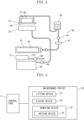
- FIG. 4 is a view schematically showing an ink supply part 60.
- the front side of the paper surface on which FIG. 1 is drawn is defined as the front side of the inkjet recording apparatus 1, and the left-and-right direction will be described with reference to the direction in which the inkjet recording apparatus 1 is viewed from the front side.
- U, Lo, L, R, Fr and Rr indicate the upper, lower, left, right, front and rear, respectively.
- the inkjet recording apparatus 1 includes a box-shaped body housing 3.
- a sheet feeding cassette 4 in which sheets S such as a plain paper and a coated paper are stored, and a sheet feeding roller 5 which feeds the sheets S rightward from the sheet feeding cassette 4 are provided.
- a conveying unit 7 which attracts and conveys the sheet S in the Y direction is provided.
- an image forming unit 6 which forms an image by ejecting ink is provided.
- a discharge roller 8 which discharges the sheet S on which the image is formed and a discharge tray 9 on which the discharged sheet S are stacked are provided.
- a conveyance path 10 is provided from the sheet feeding roller 5 to the discharge roller 8 through a gap between the conveying unit 7 and the image forming unit 6.
- the conveyance path 10 is mainly formed of plate-like members facing each other with a gap for passing the sheet S, and a conveying roller 17 for conveying the sheet S while holding the sheet S is provided at a plurality of positions in the conveyance direction Y.
- a registration roller 18 is provided on the upstream side of the image forming unit 6 in the conveyance direction Y.
- the conveying unit 7 includes an endless conveying belt 21, a support plate 23 and a suction part 24.
- the conveying belt 21 has a large number of air holes (not shown), and is wound around a driving roller 25 and a driven roller 22.
- the support plate 23 has a large number of air holes (not shown), and its upper surface is in contact with the inner surface of the conveying belt 21.
- the suction part 24 sucks air through the air holes of the conveying belt 21 and the air holes of the support plate 23, so that the sheet S is attracted to the conveying belt 21.
- a driving part including a motor and a reduction gear
- the conveying belt 21 travels in the counterclockwise direction, and the sheet S attracted to the conveying belt 21 is conveyed.
- a display operation part 19 is provided on the upper portion of the body housing 3 (see FIG. 1 , FIG. 2 ).
- the display operation part 19 includes a display panel, a touch panel laminated on the display panel, and a keypad (not shown).
- the control part 2 displays a screen representing an operation menu, a status, or the like of the inkjet recording apparatus 1 on the display panel, and controls each part of the inkjet recording apparatus 1 in accordance with the operation detected by the touch panel and the keypad.
- the frame 33 (see FIG. 8 ) is fixed to the body housing 3, and supports the carriage 34 and the conveying unit 7.
- the carriage 34 supports the removing device 32.
- the removing device 32 includes a blade 82.
- the conveying unit 7 is supported by the frame 33 via the lifting device 35 (see FIG. 5 ).
- the lifting device 35 includes, for example, a ball screw, a belt driving device, and the like.
- the lifting device 35 lifts and lowers the conveying unit 7 to an image forming position (see FIG. 6 ) when the image forming operation is performed and to a lower retracted position (see FIG. 7 ) below the image forming position.
- the conveying unit 7 When the conveying unit 7 is moved to the image forming position, the conveying unit 7 is positioned so that a distance between the conveying belt 21 and the nozzle surface14 F becomes a distance suitable for the image formation.
- a space in which the removing device 32 can be moved is formed between the upper surface of the conveying belt 21 and the nozzle surface 14F.
- the carriage 34 is supported by the frame 33 via the sliding device 36 (see FIG. 5 ).
- the sliding device 36 includes, for example, a ball screw, a belt drive device, a rack and pinion, and the like.
- the removing device 32 is supported by the carriage 34, and slides in the left-and-right direction together with the carriage 34 by the sliding device 36.
- the sliding device 36 slides the removing device 32 to a lateral retracted position (see FIG. 7 ) not facing the image forming unit 6 and a facing position (see FIG. 8 ) facing the image forming unit 6.
- FIG. 10 is a perspective view showing the removing device 32.
- FIG. 11 is a perspective view showing a blade unit 84.
- FIG. 14 to FIG. 16 are perspective views showing a cross section of the removing device 32.
- the removing device 32 includes a dipping vessel 81 and a blade unit 84 sliding with respect to the dipping vessel 81.
- the dipping vessel 81 is fixed to the carriage 34 (see FIG. 6 ).
- the dipping vessel 81 (see FIG. 10 to FIG. 16 ) has a rectangular bottom portion 81B when viewed from the upper side, and an upright side wall portion 81S provided around the entire circumference of the front, rear, right and left edges of the bottom portion 81B. In other words, the dipping vessel 81 is opened to the inkjet head 12.
- the dipping vessel 81 stores a cleaning liquid.
- the blade unit 84 (see FIG. 11 ) includes blades 82 and a support plate 83 for supporting the blades 82.
- the blade 82 is a flexible plate-like member made of rubber or the like.
- a plurality (in this embodiment, twenty) of the blades 82 are arranged in the same positional relation as the inkjet heads 12.
- the support plate 83 has a bottom portion 83B, upright side wall portions 83S provided at both right and left ends of the bottom portion 83B, and flange portions 83F protruding leftward and rightward from the left and right side wall portions 83S.
- the removing device 32 is provided with a driving device 85 (see FIG. 5 , FIG. 10 and FIG. 14 ) which slides the blade unit 84 in the front-and-rear direction.
- the driving device 85 includes support plates 85A, a ball screw 85B, rails 85R, sliding members 85S, and a driving source 85D.
- the support plates 85A are arranged below the right and left flange portions 83F, and are fixed to the dipping vessel 81 or the carriage 34.
- the ball screw 85B is provided on one of the right and left support plates 85A.
- the rails 85R are attached to the upper surfaces of the left and right support plates 85A with its longitudinal direction along the front-and-rear direction, and the sliding members 85S are attached to the lower surfaces of the left and right flange portions 83F.
- the sliding member 85S is fitted to the rail 85R, and is slidable along the rail 85R.
- the driving device 85 is merely an example, and the driving device 85 may be, for example, a belt driving device, a rack and pinion, or the like.
- the driving device 85 is provided at a position higher than the maximum height of the liquid level of the liquid which can be stored in the dipping vessel 81.
- the maximum height of the liquid surface of the liquid that can be stored in the dipping vessel 81 is equal to the height of the upper edge portion of the side wall portion 81S. According to this configuration, a possibility of infiltration of the cleaning liquid into the driving device 85 can be reduced.
- the blade unit 84 slides from a slide start position toward a slide end position.
- the slide start position is the rear end of the slidable range of the blade unit 84.
- the slide end position is the front end of the slidable range of the blade unit 84.
- FIG. 10 to FIG. 13 and FIG. 15 show the blade unit 84 in the slide start position.
- FIG. 16 shows the blade unit 84 positioned at the slide end position.
- the inkjet recording apparatus 1 includes a cleaning liquid supply device 13 for supplying the cleaning liquid to the dipping vessel 81 (see FIG. 4 ).
- the cleaning liquid supply device 13 includes a cleaning liquid tank 13T for storing the cleaning liquid, and a pump 13P for feeding the cleaning liquid from the cleaning liquid tank 13T.
- the pump 13P is connected to the dipping vessel 81.
- a suction pump 68 and a waste liquid tank 69 are connected (see FIG. 4 ).
- Thee cleaning liquid supply device 13 supplies the cleaning liquid so that a liquid level is positioned within a predetermined range above the nozzle surface 14F.
- the dipping vessel 81 is provided with a sensor 13S (see FIG. 14 ) for detecting a height of a liquid level of the cleaning liquid.
- the control part 2 drives the pump 13P so that a height of the liquid level detected by the sensor 13S is within the predetermined range above the nozzle surface 14F. According to this configuration, a possibility of infiltration of the cleaning liquid into the driving circuit 12D provided in the inkjet head 12 can be reduced.
- the removing device 32 is arranged at the lateral retracted position, and the conveying unit 7 is arranged at the image forming position.
- the purge processing and the wiping processing are performed at predetermined timing.
- the predetermined timing is, for example, when a predetermined time has elapsed since the image forming job is completed.
- the control part 2 moves the conveying unit 7 to the lower retracted position by the lifting device 35 (see FIG. 7 ), and moves the carriage 34 to the facing position by the sliding device 36 (see FIG. 8 ).
- the removing device 32 is positioned at the separated position.
- the control part 2 lifts the conveying unit 7 by the lifting device 35 to lift the removing device 32 to the contact position (see FIG. 9 ).
- the blade unit 84 is positioned at the slide start position (see FIG. 15 ). At the slide start position, the blade 82 is positioned on the rear side of the nozzle surface 14F.
- the control part 2 increases a pressure in the nozzle 14N of the inkjet head 12 to eject the ink (the purge processing).
- the control part 2 silds the blade unit 84 forward by the driving device 85 (the wiping processing).
- the blade 82 moves forward while being pressed against the nozzle surface 14F and bent, and scrapes the ink adhering to the nozzle surface 14F.
- the ink is diluted by the cleaning liquid.
- the blade unit 84 is stopped at the slide end position (see FIG. 16 ). At the slide end position, the blade 82 is positioned on the front side of the nozzle surface 14F.
- the control part 2 waits until the image forming job is input while the removing device 32 is disposed at the contact position. Since the nozzle surface 14F is dipped in the cleaning liquid during this time, an increased in viscosity of the ink in the nozzle 14N is suppressed. The ink is prevented from sticking to the nozzle surface 14F and the blade 82.
- the control part 2 When the image forming job is inputted, the control part 2 lowers the removing device 32 to the separated position by the lifting device 35 (see FIG. 8 ), slides the removing device 32 to the lateral retracted position by the sliding device 36 (see FIG. 7 ), lifts the conveying unit 7 to the image forming position by the lifting device 35 (see FIG. 6 ), and then executes the image forming job.
- the inkjet recording apparatus 1 includes the inkjet heads 12, the dipping vessel 81 which stores the cleaning liquid, the lifting device 35 which dips the nozzle surface 14F of the inkjet head 12 in the cleaning liquid by lifting or lowering the dipping vessel 81 or the inkjet head 12, and the removing device 32 which is provided in the dipping vessel 81 and removes the adhered material from the nozzle surface 14F.
- the removing device 32 removes the adhered material from the nozzle surface 14F while the nozzle surface 14F is dipped in the cleaning liquid, an ability to remove the adhered material from the nozzle surface 14F can be improved.
- the inkjet recording apparatus 1 includes the driving device 85 which drives the removing device 32, and the driving device 85 is provided at a position higher than the maximum height of the liquid surface of the liquid that can be stored in the dipping vessel 81. According to this configuration, the possibility of infiltration of the cleaning liquid into the driving device 85 can be reduced.
- the inkjet recording apparatus 1 includes the cleaning liquid supply device which supplies the cleaning liquid to the dipping vessel 81, and the cleaning liquid supply device 13 supplies the cleaning liquid so that the liquid surface is positioned within the predetermined range above the nozzle surface 14F. According to this configuration, the possibility of infiltration of the cleaning liquid into the driving circuit 12D provided in the inkjet head 12 can be reduced.
- the lifting device 35 maintains a state in which the nozzle surface 14F is dipped in the cleaning liquid during a period in which the image formation by the inkjet head 12 is not performed. With this configuration, it is possible to suppress an increase in viscosity of the ink in the nozzle 14N during a period when the image formation is not performed.
- the lifting device 35 lifts and lowers the dipping vessel 81 or the inkjet head 12 to a position where the nozzle surface 14F is not dipped in the cleaning liquid when the image formation by the inkjet head 12 is performed.
- the removing device 32 is provided with the blade 82 which removes adhered material by sliding in one direction along the nozzle surface 14F
- the driving device 85 is provided with the driving source 85D which generates a driving force
- the driving source 85D is provided closer to the slide start position than the slide end position of the blade 82. According to this configuration, the possibility of infiltration of the cleaning liquid into the driving source 85D can be reduced.
- the dipping vessel 81 may include a heater 81H (see FIG. 14 ) which heats the cleaning liquid. According to this configuration, the ink removing ability can be enhanced by softening the stuck ink and lowering the viscosity of the cleaning liquid.
- the above embodiment shows an example in which the removing device 32 is slid into the space formed by lowering the conveying unit 7, but the removing device 32 may be slid into the space formed by lifting the image forming unit 6.
Landscapes
- Ink Jet (AREA)
Abstract
An inkjet recording apparatus (1) includes an inkjet head (12), a dipping vessel (81), a lifting device (35) and a removing device (32). The dipping vessel (81) stores a cleaning liquid. The lifting device (35) dips a nozzle surface of the inkjet head (12) in the cleaning liquid by lifting or lowering the dipping vessel (81) or the inkjet head (12). The removing device (32) is provided in the dipping vessel (81) and removes adhered material from the nozzle surface.
Description
- The present disclosure relates to an inkjet recording apparatus.
- In an inkjet recording apparatus, moisture evaporates from ink in a nozzle of an inkjet head during a period when an image forming job is not executed, and the nozzle may be clogged by an increase in viscosity of the ink. To prevent the clogging, the ink in the nozzle is purged to the cap. However, if the ink remaining on the nozzle surface is left, there is a problem that the ink falls on the sheet during the execution of the image forming job or the ink sticks to the nozzle surface. Therefore, a technique for removing the ink remaining on the nozzle surface has been studied. For example,
JP2018-108711 - In the above configuration, since a cleaning liquid is swelled from a hole of a supply member adjacent to the nozzle surface and the blade slides along the nozzle surface after scraping the cleaning liquid, there is a problem that an amount of the cleaning liquid supplied to the nozzle surface is small, and an ability for removing adhered material from the nozzle surface is low.
- An inkjet recording apparatus according to the present disclosure includes an inkjet head, a dipping vessel, a lifting device and a removing device. The dipping vessel stores a cleaning liquid. The lifting device dips a nozzle surface of the inkjet head in the cleaning liquid by lifting or lowering the dipping vessel or the inkjet head. The removing device is provided in the dipping vessel and removes adhered material from the nozzle surface.
-
-
FIG. 1 is a front view schematically showing an internal configuration of an inkjet recording apparatus according to one embodiment of the present disclosure. -
FIG. 2 is a perspective view showing an arrangement of inkjet heads according to the embodiment of the present disclosure. -
FIG. 3 is a cross-sectional view showing the inkjet head according to the embodiment of the present disclosure. -
FIG. 4 is a diagram schematically showing a configuration of an ink supply part according to the embodiment of the present disclosure. -
FIG. 5 is a block diagram showing an electrical configuration of a maintenance device according to the embodiment of the present disclosure. -
FIG. 6 is a perspective view showing an image forming unit according to the embodiment of the present disclosure. -
FIG. 7 is a disassembled view showing the image forming unit according to the embodiment of the present disclosure. -
FIG. 8 is a perspective view showing the maintenance device according to the embodiment of the present disclosure. -
FIG. 9 is a perspective view showing the maintenance device according to the embodiment of the present disclosure. -
FIG. 10 is a perspective view showing a removing device according to the embodiment of the present disclosure. -
FIG. 11 is a perspective view showing a blade unit according to the embodiment of the present disclosure. -
FIG. 12 is a perspective view showing a cross section of the removing device according to the embodiment of the present disclosure. -
FIG. 13 is a perspective view showing a cross section of the removing device according to the embodiment of the present disclosure. -
FIG. 14 is a cross-sectional view showing the removing device according to the embodiment of the present disclosure. -
FIG. 15 is a cross-sectional view showing the removing device according to the embodiment of the present disclosure. -
FIG. 16 is a cross-sectional view showing the removing device according to the embodiment of the present disclosure. - Hereinafter, with reference to the drawings, an inkjet recording apparatus 1 according to the present embodiment of the present disclosure will be described.
- First, an entire configuration of the inkjet recording apparatus 1 will be described.
FIG. 1 is a front view schematically showing the inkjet recording apparatus 1.FIG. 2 is a perspective view showing an arrangement ofinkjet heads 12.FIG. 3 is a cross-sectional view showing theinkjet head 12.FIG. 4 is a view schematically showing anink supply part 60. Hereinafter, the front side of the paper surface on whichFIG. 1 is drawn is defined as the front side of the inkjet recording apparatus 1, and the left-and-right direction will be described with reference to the direction in which the inkjet recording apparatus 1 is viewed from the front side. In each drawing, U, Lo, L, R, Fr and Rr indicate the upper, lower, left, right, front and rear, respectively. - The inkjet recording apparatus 1 (see
FIG. 1 ) includes a box-shaped body housing 3. In the lower portion in the body housing 3, asheet feeding cassette 4 in which sheets S such as a plain paper and a coated paper are stored, and a sheet feeding roller 5 which feeds the sheets S rightward from thesheet feeding cassette 4 are provided. Above thesheet feeding cassette 4, aconveying unit 7 which attracts and conveys the sheet S in the Y direction is provided. Above theconveying unit 7, animage forming unit 6 which forms an image by ejecting ink is provided. In the right upper portion in the body housing 3, adischarge roller 8 which discharges the sheet S on which the image is formed and adischarge tray 9 on which the discharged sheet S are stacked are provided. - Inside the body housing 3, a
conveyance path 10 is provided from the sheet feeding roller 5 to thedischarge roller 8 through a gap between theconveying unit 7 and theimage forming unit 6. Theconveyance path 10 is mainly formed of plate-like members facing each other with a gap for passing the sheet S, and aconveying roller 17 for conveying the sheet S while holding the sheet S is provided at a plurality of positions in the conveyance direction Y. Aregistration roller 18 is provided on the upstream side of theimage forming unit 6 in the conveyance direction Y. - The
conveying unit 7 includes anendless conveying belt 21, asupport plate 23 and asuction part 24. Theconveying belt 21 has a large number of air holes (not shown), and is wound around adriving roller 25 and a drivenroller 22. Thesupport plate 23 has a large number of air holes (not shown), and its upper surface is in contact with the inner surface of theconveying belt 21. Thesuction part 24 sucks air through the air holes of theconveying belt 21 and the air holes of thesupport plate 23, so that the sheet S is attracted to theconveying belt 21. When thedriving roller 25 is driven in the counterclockwise direction by a driving part (not shown) including a motor and a reduction gear, theconveying belt 21 travels in the counterclockwise direction, and the sheet S attracted to theconveying belt 21 is conveyed. - The
image forming unit 6 includeshead units 11Y, 11Bk, 11C and 11M (collectively referred to as the head unit 11). Thehead unit 11 includes one ormore inkjet heads 12, for example, threeinkjet heads 12 arranged in a staggered pattern (seeFIG. 2 ).Ink containers 20Y, 20Bk, 20C and 20M (collectively referred to as the ink container 20) filled with the black, cyan, magenta, and yellow ink are connected to therespective head units 11. - The inkjet head 12 (see
FIG. 3 ) includes a rectangularparallelepiped housing 12H whose longitudinal direction is along the front-and-rear direction, anozzle plate 14 provided at the bottom of thehousing 12H, and asocket 12S to which a pipe for supplying the ink is connected. Thenozzle plate 14 is provided with a large number ofnozzles 14N arranged in the front-and-rear direction. Thenozzle 14N includes abranch channel 14B branched from the downstream side of thesocket 12S, and anejection port 14A provided on anozzle surface 14F which is the lower surface of thenozzle plate 14. Adiaphragm 14V also serves as a part of the inner wall of thebranch channel 14B. Thediaphragm 14V is provided with a pressurizingelement 14Z. As the pressurizingelement 14Z, a piezoelectric element, an electrostatic actuator, a heater or the like are used. Adriving circuit 12D for driving the pressurizingelement 14Z is connected to the pressurizingelement 14Z. - The inkjet recording apparatus 1 includes an ink supply part 60 (see
FIG. 4 ). In the figure, oneink supply part 60 corresponding to one color ink is shown, but since the four colors of the ink are used in this embodiment, the same fourink supply parts 60 are provided. The inkjet recording apparatus 1 includes acontainer attachment part 61 to which theink container 20 is attached, afilter 62 which filters the ink, apump 63 which sucks the ink from theink container 20 through thefilter 62, and asub-tank 64 which stores the ink fed from thepump 63. - A liquid level in the sub-tank 64 is adjusted to be slightly lower than the
nozzle surface 14F. Negative pressure acts on the ink in thenozzle 14N by a head difference between the liquid surface and thenozzle surface 14F, and a meniscus is formed in thenozzle 14N. After the ink is ejected from theinkjet head 12, a surface tension of the ink acts to reduce the surface area of the meniscus, and the ink of the reduced amount is drawn into theinkjet head 12 from the sub-tank 64 by a negative pressure generated thereby. - A control part 2 (see
FIG. 1 ) includes an arithmetic part and a storage part (not shown). The arithmetic part is, for example, a CPU (Central Processing Unit). The storage part includes a storage medium such as ROM (Read Only Memory), RAM (Random Access Memory), EEPROM (Electrically Erasable Programmable Read Only Memory), and the like. The arithmetic part reads the control program stored in the storage part and executes various processes. Thecontrol part 2 may be implemented by an integrated circuit that does not use software. - A
display operation part 19 is provided on the upper portion of the body housing 3 (seeFIG. 1 ,FIG. 2 ). Thedisplay operation part 19 includes a display panel, a touch panel laminated on the display panel, and a keypad (not shown). Thecontrol part 2 displays a screen representing an operation menu, a status, or the like of the inkjet recording apparatus 1 on the display panel, and controls each part of the inkjet recording apparatus 1 in accordance with the operation detected by the touch panel and the keypad. - The basic image forming operation of the inkjet recording apparatus 1 is as follows. When an image forming job is inputted to the inkjet recording apparatus 1 from the
display operation part 19 or an external computer, the sheet feeding roller 5 feeds the sheet S from thesheet feeding cassette 4 to theconveyance path 10, and theregistration roller 18 whose rotation is stopped corrects the skew of the sheet S. When theregistration roller 18 sends the sheet S to the conveyingunit 7 at a predetermined timing, the conveyingunit 7 attracts the sheet S to the conveyingbelt 21, and conveys the sheet S in the Y direction. The drivingcircuit 12D supplies an ejection signal corresponding to the image data to the pressurizingelement 14Z in synchronization with the conveyance of the sheet S. Thus, the ink is ejected from thenozzle 14N to form an image on the sheet S. Thedischarge roller 8 discharges the sheet S on which the image is formed to thedischarge tray 9. - [Maintenance Device]
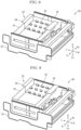
FIG. 5 is a block diagram showing an electrical configuration of themaintenance device 30.FIG. 6 to FIG. 9 are perspective views showing themaintenance device 30. Themaintenance device 30 includes aframe 33, acarriage 34, a removingdevice 32, alifting device 35, and a slidingdevice 36. - [Frame, Carriage] The frame 33 (see
FIG. 8 ) is fixed to the body housing 3, and supports thecarriage 34 and the conveyingunit 7. Thecarriage 34 supports the removingdevice 32. The removingdevice 32 includes ablade 82. - [Lifting Device] The conveying
unit 7 is supported by theframe 33 via the lifting device 35 (seeFIG. 5 ). The liftingdevice 35 includes, for example, a ball screw, a belt driving device, and the like. The liftingdevice 35 lifts and lowers the conveyingunit 7 to an image forming position (seeFIG. 6 ) when the image forming operation is performed and to a lower retracted position (seeFIG. 7 ) below the image forming position. When the conveyingunit 7 is moved to the image forming position, the conveyingunit 7 is positioned so that a distance between the conveyingbelt 21 and the nozzle surface14 F becomes a distance suitable for the image formation. When the conveyingunit 7 is moved to the lower retracted position, a space in which the removingdevice 32 can be moved is formed between the upper surface of the conveyingbelt 21 and thenozzle surface 14F. - [Sliding Device] The
carriage 34 is supported by theframe 33 via the sliding device 36 (seeFIG. 5 ). The slidingdevice 36 includes, for example, a ball screw, a belt drive device, a rack and pinion, and the like. The removingdevice 32 is supported by thecarriage 34, and slides in the left-and-right direction together with thecarriage 34 by the slidingdevice 36. When the conveyingunit 7 is positioned at the lower retracted position, the slidingdevice 36 slides the removingdevice 32 to a lateral retracted position (seeFIG. 7 ) not facing theimage forming unit 6 and a facing position (seeFIG. 8 ) facing theimage forming unit 6. - In the facing position, the removing
device 32 can be moved upward and downward by using the conveyingunit 7. Specifically, the conveyingunit 7 can move upward and downward inside thecarriage 34 with the removingdevice 32 placed on the upper portion of the conveyingunit 7. The liftingdevice 35 lifts and lowers the removingdevice 32 to a separated position where theblade 82 is separated from thenozzle surface 14F (seeFIG. 8 ) and a contact position where theblade 82 comes into contact with thenozzle surface 14F (seeFIG. 9 ). - [Removing Device]
FIG. 10 is a perspective view showing the removingdevice 32.FIG. 11 is a perspective view showing ablade unit 84.FIG. 14 to FIG. 16 are perspective views showing a cross section of the removingdevice 32. The removingdevice 32 includes a dippingvessel 81 and ablade unit 84 sliding with respect to the dippingvessel 81. - [Dipping Vessel] The dipping
vessel 81 is fixed to the carriage 34 (seeFIG. 6 ). The dipping vessel 81 (seeFIG. 10 to FIG. 16 ) has arectangular bottom portion 81B when viewed from the upper side, and an uprightside wall portion 81S provided around the entire circumference of the front, rear, right and left edges of thebottom portion 81B. In other words, the dippingvessel 81 is opened to theinkjet head 12. The dippingvessel 81 stores a cleaning liquid. - [Blade Unit] The blade unit 84 (see
FIG. 11 ) includesblades 82 and asupport plate 83 for supporting theblades 82. Theblade 82 is a flexible plate-like member made of rubber or the like. A plurality (in this embodiment, twenty) of theblades 82 are arranged in the same positional relation as the inkjet heads 12. Thesupport plate 83 has abottom portion 83B, uprightside wall portions 83S provided at both right and left ends of thebottom portion 83B, andflange portions 83F protruding leftward and rightward from the left and rightside wall portions 83S. - [Driving Device] The removing
device 32 is provided with a driving device 85 (seeFIG. 5 ,FIG. 10 andFIG. 14 ) which slides theblade unit 84 in the front-and-rear direction. The drivingdevice 85 includessupport plates 85A, aball screw 85B, rails 85R, slidingmembers 85S, and adriving source 85D. Thesupport plates 85A are arranged below the right and leftflange portions 83F, and are fixed to the dippingvessel 81 or thecarriage 34. Theball screw 85B is provided on one of the right and leftsupport plates 85A. A screw shaft 85BS is attached to the upper surface of thesupport plate 85A with its axial direction along the front-and-rear direction, and a nut 85BN is attached to the lower surface of theflange portion 83F above the screw shaft 85BS. The drivingsource 85D includes a motor, a reduction gear, and the others. - The
rails 85R are attached to the upper surfaces of the left andright support plates 85A with its longitudinal direction along the front-and-rear direction, and the slidingmembers 85S are attached to the lower surfaces of the left andright flange portions 83F. The slidingmember 85S is fitted to therail 85R, and is slidable along therail 85R. When the screw shaft 85BS is driven by the drivingsource 85D, theblade unit 84 slides in the front-and-rear direction together with the nut 85BN. The drivingdevice 85 is merely an example, and the drivingdevice 85 may be, for example, a belt driving device, a rack and pinion, or the like. - The driving
device 85 is provided at a position higher than the maximum height of the liquid level of the liquid which can be stored in the dippingvessel 81. For example, in this embodiment, since the upper edge portion of theside wall portion 81S of the dippingvessel 81 is formed at the same height over the entire circumference, the maximum height of the liquid surface of the liquid that can be stored in the dippingvessel 81 is equal to the height of the upper edge portion of theside wall portion 81S. According to this configuration, a possibility of infiltration of the cleaning liquid into the drivingdevice 85 can be reduced. - In the case of performing wipe processing for removing adhered material from the
nozzle surface 14F, theblade unit 84 slides from a slide start position toward a slide end position. In this embodiment, the slide start position is the rear end of the slidable range of theblade unit 84. The slide end position is the front end of the slidable range of theblade unit 84.FIG. 10 to FIG. 13 andFIG. 15 show theblade unit 84 in the slide start position.FIG. 16 shows theblade unit 84 positioned at the slide end position. - Since the
blade 82 moves in the cleaning liquid during the wiping processing, splashes of the cleaning liquid may be generated. The drivingsource 85D is provided closer to the slide start position than the slide end position of theblade 82. According to this configuration, since theblade 82 moves in a direction away from the drivingsource 85D during the wiping processing, the possibility of infiltration of the cleaning liquid into the drivingsource 85D can be reduced. - [Cleaning Liquid Supply Device] The inkjet recording apparatus 1 includes a cleaning
liquid supply device 13 for supplying the cleaning liquid to the dipping vessel 81 (seeFIG. 4 ). The cleaningliquid supply device 13 includes a cleaningliquid tank 13T for storing the cleaning liquid, and apump 13P for feeding the cleaning liquid from the cleaningliquid tank 13T. Thepump 13P is connected to the dippingvessel 81. To the dippingvessel 81, asuction pump 68 and awaste liquid tank 69 are connected (seeFIG. 4 ). - Thee cleaning
liquid supply device 13 supplies the cleaning liquid so that a liquid level is positioned within a predetermined range above thenozzle surface 14F. For example, the dippingvessel 81 is provided with asensor 13S (seeFIG. 14 ) for detecting a height of a liquid level of the cleaning liquid. Thecontrol part 2 drives thepump 13P so that a height of the liquid level detected by thesensor 13S is within the predetermined range above thenozzle surface 14F. According to this configuration, a possibility of infiltration of the cleaning liquid into thedriving circuit 12D provided in theinkjet head 12 can be reduced. - Next, an operation of the
maintenance device 30 will be described. The following operations are executed by thecontrol part 2 controlling the respective parts of themaintenance device 30. - When the image forming job is executed (see
FIG. 6 ), the removingdevice 32 is arranged at the lateral retracted position, and the conveyingunit 7 is arranged at the image forming position. - The purge processing and the wiping processing are performed at predetermined timing. The predetermined timing is, for example, when a predetermined time has elapsed since the image forming job is completed. In the case of performing the purge processing and the wiping processing, the
control part 2 moves the conveyingunit 7 to the lower retracted position by the lifting device 35 (seeFIG. 7 ), and moves thecarriage 34 to the facing position by the sliding device 36 (seeFIG. 8 ). At this time, the removingdevice 32 is positioned at the separated position. Next, thecontrol part 2 lifts the conveyingunit 7 by the liftingdevice 35 to lift the removingdevice 32 to the contact position (seeFIG. 9 ). - The
blade unit 84 is positioned at the slide start position (seeFIG. 15 ). At the slide start position, theblade 82 is positioned on the rear side of thenozzle surface 14F. - Subsequently, the
control part 2 increases a pressure in thenozzle 14N of theinkjet head 12 to eject the ink (the purge processing). Next, thecontrol part 2 silds theblade unit 84 forward by the driving device 85 (the wiping processing). Theblade 82 moves forward while being pressed against thenozzle surface 14F and bent, and scrapes the ink adhering to thenozzle surface 14F. The ink is diluted by the cleaning liquid. Theblade unit 84 is stopped at the slide end position (seeFIG. 16 ). At the slide end position, theblade 82 is positioned on the front side of thenozzle surface 14F. - After the wiping processing is completed, the
control part 2 waits until the image forming job is input while the removingdevice 32 is disposed at the contact position. Since thenozzle surface 14F is dipped in the cleaning liquid during this time, an increased in viscosity of the ink in thenozzle 14N is suppressed. The ink is prevented from sticking to thenozzle surface 14F and theblade 82. - When the image forming job is inputted, the
control part 2 lowers the removingdevice 32 to the separated position by the lifting device 35 (seeFIG. 8 ), slides the removingdevice 32 to the lateral retracted position by the sliding device 36 (seeFIG. 7 ), lifts the conveyingunit 7 to the image forming position by the lifting device 35 (seeFIG. 6 ), and then executes the image forming job. - The inkjet recording apparatus 1 according to the embodiment described above includes the inkjet heads 12, the dipping
vessel 81 which stores the cleaning liquid, the liftingdevice 35 which dips thenozzle surface 14F of theinkjet head 12 in the cleaning liquid by lifting or lowering the dippingvessel 81 or theinkjet head 12, and the removingdevice 32 which is provided in the dippingvessel 81 and removes the adhered material from thenozzle surface 14F. According to this configuration, since the removingdevice 32 removes the adhered material from thenozzle surface 14F while thenozzle surface 14F is dipped in the cleaning liquid, an ability to remove the adhered material from thenozzle surface 14F can be improved. - Further, the inkjet recording apparatus 1 according to the present embodiment includes the driving
device 85 which drives the removingdevice 32, and the drivingdevice 85 is provided at a position higher than the maximum height of the liquid surface of the liquid that can be stored in the dippingvessel 81. According to this configuration, the possibility of infiltration of the cleaning liquid into the drivingdevice 85 can be reduced. - Further, the inkjet recording apparatus 1 according to the present embodiment includes the cleaning liquid supply device which supplies the cleaning liquid to the dipping
vessel 81, and the cleaningliquid supply device 13 supplies the cleaning liquid so that the liquid surface is positioned within the predetermined range above thenozzle surface 14F. According to this configuration, the possibility of infiltration of the cleaning liquid into thedriving circuit 12D provided in theinkjet head 12 can be reduced. - Further, according to the inkjet recording apparatus 1 according to the present embodiment, the lifting
device 35 maintains a state in which thenozzle surface 14F is dipped in the cleaning liquid during a period in which the image formation by theinkjet head 12 is not performed. With this configuration, it is possible to suppress an increase in viscosity of the ink in thenozzle 14N during a period when the image formation is not performed. - Further, according to the inkjet recording apparatus 1 according to the present embodiment, the lifting
device 35 lifts and lowers the dippingvessel 81 or theinkjet head 12 to a position where thenozzle surface 14F is not dipped in the cleaning liquid when the image formation by theinkjet head 12 is performed. With this configuration, it is possible to suppress an increase in viscosity of the ink in thenozzle 14N during a period when the image formation is not performed. - Further, according to the inkjet recording apparatus 1 according to the present embodiment, the removing
device 32 is provided with theblade 82 which removes adhered material by sliding in one direction along thenozzle surface 14F, the drivingdevice 85 is provided with the drivingsource 85D which generates a driving force, and the drivingsource 85D is provided closer to the slide start position than the slide end position of theblade 82. According to this configuration, the possibility of infiltration of the cleaning liquid into the drivingsource 85D can be reduced. - The above embodiment may be modified as follows.
- In addition to the configuration of the above embodiment, the dipping
vessel 81 may include aheater 81H (seeFIG. 14 ) which heats the cleaning liquid. According to this configuration, the ink removing ability can be enhanced by softening the stuck ink and lowering the viscosity of the cleaning liquid. - The above embodiment shows an example in which the removing
device 32 is slid into the space formed by lowering the conveyingunit 7, but the removingdevice 32 may be slid into the space formed by lifting theimage forming unit 6.
Claims (7)
- An inkjet recording apparatus (1) comprising:an inkjet head (12);a dipping vessel (81) which stores a cleaning liquid;a lifting device (35) which dips a nozzle surface of the inkjet head (12) in the cleaning liquid by lifting or lowering the dipping vessel (81) or the inkjet head 812); anda removing device (32) which is provided in the dipping vessel (81) and removes adhered material from the nozzle surface.
- The inkjet recording apparatus (1) according to claim 1, comprising:a driving device (85) which drives the removing device (32), whereinthe driving device (85) is provided at a position higher than a maximum height of the liquid surface of the liquid that can be stored in the dipping vessel (81) .
- The inkjet recording apparatus (1) according to claim 1, comprising:a cleaning liquid supply device (13) which supplies the cleaning liquid to the dipping vessel (81), whereinthe cleaning liquid supply device (13) supplies the cleaning liquid so that a liquid surface is positioned within a predetermined range above the nozzle surface.
- The inkjet recording apparatus (1) according to claim 1, wherein
the lifting device (35) maintains a state in which the nozzle surface is dipped in the cleaning liquid during a period in which an image formation by the inkjet head (12) is not performed. - The inkjet recording apparatus (1) according to claim 1, wherein
the lifting device (35) lifts and lowers the dipping vessel (81) or the inkjet head (12) to a position where the nozzle surface is not dipped in the cleaning liquid when the image formation by the inkjet head is performed. - The inkjet recording apparatus (1) according to claim 2, whereinthe removing device (32) is provided with a blade (82) which removes adhered material by sliding in one direction along the nozzle surface,the driving device (85) is provided with a driving source (85D) which generates a driving force, andthe driving source (85D) is provided closer to a slide start position than a slide end position of the blade (82).
- The inkjet recoding apparatus (1) according to claim 1, wherein
the dipping vessel (81) is provided with a heater (81H) which heats the cleaning liquid.
Applications Claiming Priority (1)
| Application Number | Priority Date | Filing Date | Title |
|---|---|---|---|
| JP2023206163A JP2025091114A (en) | 2023-12-06 | 2023-12-06 | Inkjet recording device |
Publications (1)
| Publication Number | Publication Date |
|---|---|
| EP4566822A1 true EP4566822A1 (en) | 2025-06-11 |
Family
ID=93744006
Family Applications (1)
| Application Number | Title | Priority Date | Filing Date |
|---|---|---|---|
| EP24216749.2A Pending EP4566822A1 (en) | 2023-12-06 | 2024-12-02 | Inkjet recording apparatus |
Country Status (3)
| Country | Link |
|---|---|
| US (1) | US20250187341A1 (en) |
| EP (1) | EP4566822A1 (en) |
| JP (1) | JP2025091114A (en) |
Citations (4)
| Publication number | Priority date | Publication date | Assignee | Title |
|---|---|---|---|---|
| US20160152033A1 (en) * | 2014-12-01 | 2016-06-02 | Seiko Epson Corporation | Liquid Ejecting Apparatus, Ultrasonic Cleaning Device, and Ultrasonic Cleaning Method |
| US20170100937A1 (en) * | 2014-03-25 | 2017-04-13 | Mimaki Engineering Co., Ltd. | Head cleaning apparatus, inkjet printer and head cleaning method |
| JP2018108711A (en) | 2017-01-06 | 2018-07-12 | 京セラドキュメントソリューションズ株式会社 | RECORDING HEAD AND INKJET RECORDING DEVICE EQUIPPED WITH THE SAME |
| CN114851713A (en) * | 2022-05-30 | 2022-08-05 | 新明珠集团股份有限公司 | Ceramic printer nozzle cleaning system and cleaning method thereof |
Family Cites Families (4)
| Publication number | Priority date | Publication date | Assignee | Title |
|---|---|---|---|---|
| JP2006272097A (en) * | 2005-03-28 | 2006-10-12 | Seiko Epson Corp | NOZZLE CLEANING DEVICE, DROPLET DISCHARGE DEVICE EQUIPPED WITH THE SAME, ELECTRO-OPTICAL DEVICE MANUFACTURING METHOD, ELECTRO-OPTICAL DEVICE, AND ELECTRONIC DEVICE |
| JP2007163751A (en) * | 2005-12-13 | 2007-06-28 | Seiko Epson Corp | Wiping device, droplet discharge device, electro-optical device manufacturing method, electro-optical device, and electronic apparatus |
| JP2012176544A (en) * | 2011-02-25 | 2012-09-13 | Fujifilm Corp | Ink jet head, ink jet head cleaning device and ink jet recording device |
| JP2024158035A (en) * | 2023-04-27 | 2024-11-08 | 京セラドキュメントソリューションズ株式会社 | Inkjet recording device |
-
2023
- 2023-12-06 JP JP2023206163A patent/JP2025091114A/en active Pending
-
2024
- 2024-12-02 EP EP24216749.2A patent/EP4566822A1/en active Pending
- 2024-12-04 US US18/969,196 patent/US20250187341A1/en active Pending
Patent Citations (4)
| Publication number | Priority date | Publication date | Assignee | Title |
|---|---|---|---|---|
| US20170100937A1 (en) * | 2014-03-25 | 2017-04-13 | Mimaki Engineering Co., Ltd. | Head cleaning apparatus, inkjet printer and head cleaning method |
| US20160152033A1 (en) * | 2014-12-01 | 2016-06-02 | Seiko Epson Corporation | Liquid Ejecting Apparatus, Ultrasonic Cleaning Device, and Ultrasonic Cleaning Method |
| JP2018108711A (en) | 2017-01-06 | 2018-07-12 | 京セラドキュメントソリューションズ株式会社 | RECORDING HEAD AND INKJET RECORDING DEVICE EQUIPPED WITH THE SAME |
| CN114851713A (en) * | 2022-05-30 | 2022-08-05 | 新明珠集团股份有限公司 | Ceramic printer nozzle cleaning system and cleaning method thereof |
Also Published As
| Publication number | Publication date |
|---|---|
| US20250187341A1 (en) | 2025-06-12 |
| JP2025091114A (en) | 2025-06-18 |
Similar Documents
| Publication | Publication Date | Title |
|---|---|---|
| CN115139652B (en) | inkjet recording device | |
| EP1642721B1 (en) | Liquid-discharging device | |
| US8733891B2 (en) | Inkjet recording apparatus | |
| JP4349411B2 (en) | Liquid ejection device | |
| JP2013144394A (en) | Liquid ejection apparatus | |
| US11554587B2 (en) | Inkjet recording apparatus | |
| JP5948943B2 (en) | Image recording device | |
| US20250187341A1 (en) | Inkjet recording apparatus | |
| EP4566821A1 (en) | Inkjet recording apparatus | |
| JP6248514B2 (en) | Image forming apparatus and nozzle diagnosis and discharge recovery method | |
| JP2013035174A (en) | Liquid ejection apparatus | |
| JP2019018355A (en) | Recording head and ink jet recording apparatus provided with the same | |
| EP4684968A1 (en) | Cleaning liquid penetration device and inkjet recording apparatus | |
| EP4684969A1 (en) | Cleaning liquid penetration device and inkjet recording apparatus | |
| US20240416657A1 (en) | Inkjet recording apparatus | |
| US20240359470A1 (en) | Inkjet recording apparatus | |
| US20240359469A1 (en) | Inkjet recording apparatus | |
| US11554588B2 (en) | Inkjet recording apparatus | |
| JP2025091279A (en) | Inkjet recording device | |
| JP2019069540A (en) | Inkjet recording device | |
| JP2022168508A (en) | Maintenance device and ink jet recording device | |
| JP2025091280A (en) | Inkjet recording device | |
| JP6680193B2 (en) | Head cleaning mechanism and inkjet recording apparatus including the same | |
| JP2019025740A (en) | Recording head and ink jet recording apparatus provided with the same | |
| JP5712893B2 (en) | Liquid ejection device and method for sealing the ejection space thereof |
Legal Events
| Date | Code | Title | Description |
|---|---|---|---|
| PUAI | Public reference made under article 153(3) epc to a published international application that has entered the european phase |
Free format text: ORIGINAL CODE: 0009012 |
|
| STAA | Information on the status of an ep patent application or granted ep patent |
Free format text: STATUS: THE APPLICATION HAS BEEN PUBLISHED |
|
| AK | Designated contracting states |
Kind code of ref document: A1 Designated state(s): AL AT BE BG CH CY CZ DE DK EE ES FI FR GB GR HR HU IE IS IT LI LT LU LV MC ME MK MT NL NO PL PT RO RS SE SI SK SM TR |
|
| STAA | Information on the status of an ep patent application or granted ep patent |
Free format text: STATUS: REQUEST FOR EXAMINATION WAS MADE |
|
| 17P | Request for examination filed |
Effective date: 20250922 |