EP4563830A1 - Bone screw - Google Patents
Bone screw Download PDFInfo
- Publication number
- EP4563830A1 EP4563830A1 EP23846264.2A EP23846264A EP4563830A1 EP 4563830 A1 EP4563830 A1 EP 4563830A1 EP 23846264 A EP23846264 A EP 23846264A EP 4563830 A1 EP4563830 A1 EP 4563830A1
- Authority
- EP
- European Patent Office
- Prior art keywords
- bone screw
- thread
- shaft
- screw according
- head
- Prior art date
- Legal status (The legal status is an assumption and is not a legal conclusion. Google has not performed a legal analysis and makes no representation as to the accuracy of the status listed.)
- Pending
Links
Images



Classifications
-
- A—HUMAN NECESSITIES
- A61—MEDICAL OR VETERINARY SCIENCE; HYGIENE
- A61B—DIAGNOSIS; SURGERY; IDENTIFICATION
- A61B17/00—Surgical instruments, devices or methods
- A61B17/56—Surgical instruments or methods for treatment of bones or joints; Devices specially adapted therefor
- A61B17/58—Surgical instruments or methods for treatment of bones or joints; Devices specially adapted therefor for osteosynthesis, e.g. bone plates, screws or setting implements
- A61B17/68—Internal fixation devices, including fasteners and spinal fixators, even if a part thereof projects from the skin
- A61B17/70—Spinal positioners or stabilisers, e.g. stabilisers comprising fluid filler in an implant
-
- A—HUMAN NECESSITIES
- A61—MEDICAL OR VETERINARY SCIENCE; HYGIENE
- A61B—DIAGNOSIS; SURGERY; IDENTIFICATION
- A61B17/00—Surgical instruments, devices or methods
- A61B17/56—Surgical instruments or methods for treatment of bones or joints; Devices specially adapted therefor
- A61B17/58—Surgical instruments or methods for treatment of bones or joints; Devices specially adapted therefor for osteosynthesis, e.g. bone plates, screws or setting implements
- A61B17/68—Internal fixation devices, including fasteners and spinal fixators, even if a part thereof projects from the skin
- A61B17/84—Fasteners therefor or fasteners being internal fixation devices
- A61B17/86—Pins or screws or threaded wires; nuts therefor
- A61B17/8685—Pins or screws or threaded wires; nuts therefor comprising multiple separate parts
-
- F—MECHANICAL ENGINEERING; LIGHTING; HEATING; WEAPONS; BLASTING
- F16—ENGINEERING ELEMENTS AND UNITS; GENERAL MEASURES FOR PRODUCING AND MAINTAINING EFFECTIVE FUNCTIONING OF MACHINES OR INSTALLATIONS; THERMAL INSULATION IN GENERAL
- F16B—DEVICES FOR FASTENING OR SECURING CONSTRUCTIONAL ELEMENTS OR MACHINE PARTS TOGETHER, e.g. NAILS, BOLTS, CIRCLIPS, CLAMPS, CLIPS OR WEDGES; JOINTS OR JOINTING
- F16B35/00—Screw-bolts; Stay-bolts; Screw-threaded studs; Screws; Set screws
- F16B35/04—Screw-bolts; Stay-bolts; Screw-threaded studs; Screws; Set screws with specially-shaped head or shaft in order to fix the bolt on or in an object
-
- A—HUMAN NECESSITIES
- A61—MEDICAL OR VETERINARY SCIENCE; HYGIENE
- A61B—DIAGNOSIS; SURGERY; IDENTIFICATION
- A61B17/00—Surgical instruments, devices or methods
- A61B17/56—Surgical instruments or methods for treatment of bones or joints; Devices specially adapted therefor
- A61B17/58—Surgical instruments or methods for treatment of bones or joints; Devices specially adapted therefor for osteosynthesis, e.g. bone plates, screws or setting implements
- A61B17/68—Internal fixation devices, including fasteners and spinal fixators, even if a part thereof projects from the skin
- A61B17/84—Fasteners therefor or fasteners being internal fixation devices
- A61B17/86—Pins or screws or threaded wires; nuts therefor
-
- A—HUMAN NECESSITIES
- A61—MEDICAL OR VETERINARY SCIENCE; HYGIENE
- A61B—DIAGNOSIS; SURGERY; IDENTIFICATION
- A61B17/00—Surgical instruments, devices or methods
- A61B17/56—Surgical instruments or methods for treatment of bones or joints; Devices specially adapted therefor
- A61B17/58—Surgical instruments or methods for treatment of bones or joints; Devices specially adapted therefor for osteosynthesis, e.g. bone plates, screws or setting implements
- A61B17/68—Internal fixation devices, including fasteners and spinal fixators, even if a part thereof projects from the skin
- A61B17/84—Fasteners therefor or fasteners being internal fixation devices
- A61B17/86—Pins or screws or threaded wires; nuts therefor
- A61B17/8605—Heads, i.e. proximal ends projecting from bone
- A61B17/861—Heads, i.e. proximal ends projecting from bone specially shaped for gripping driver
- A61B17/862—Heads, i.e. proximal ends projecting from bone specially shaped for gripping driver at the periphery of the screw head
-
- A—HUMAN NECESSITIES
- A61—MEDICAL OR VETERINARY SCIENCE; HYGIENE
- A61B—DIAGNOSIS; SURGERY; IDENTIFICATION
- A61B17/00—Surgical instruments, devices or methods
- A61B17/56—Surgical instruments or methods for treatment of bones or joints; Devices specially adapted therefor
- A61B17/58—Surgical instruments or methods for treatment of bones or joints; Devices specially adapted therefor for osteosynthesis, e.g. bone plates, screws or setting implements
- A61B17/68—Internal fixation devices, including fasteners and spinal fixators, even if a part thereof projects from the skin
- A61B17/84—Fasteners therefor or fasteners being internal fixation devices
- A61B17/86—Pins or screws or threaded wires; nuts therefor
- A61B17/8625—Shanks, i.e. parts contacting bone tissue
- A61B17/863—Shanks, i.e. parts contacting bone tissue with thread interrupted or changing its form along shank, other than constant taper
-
- A—HUMAN NECESSITIES
- A61—MEDICAL OR VETERINARY SCIENCE; HYGIENE
- A61B—DIAGNOSIS; SURGERY; IDENTIFICATION
- A61B17/00—Surgical instruments, devices or methods
- A61B17/56—Surgical instruments or methods for treatment of bones or joints; Devices specially adapted therefor
- A61B17/58—Surgical instruments or methods for treatment of bones or joints; Devices specially adapted therefor for osteosynthesis, e.g. bone plates, screws or setting implements
- A61B17/68—Internal fixation devices, including fasteners and spinal fixators, even if a part thereof projects from the skin
- A61B17/84—Fasteners therefor or fasteners being internal fixation devices
- A61B17/86—Pins or screws or threaded wires; nuts therefor
- A61B17/864—Pins or screws or threaded wires; nuts therefor hollow, e.g. with socket or cannulated
-
- A—HUMAN NECESSITIES
- A61—MEDICAL OR VETERINARY SCIENCE; HYGIENE
- A61B—DIAGNOSIS; SURGERY; IDENTIFICATION
- A61B17/00—Surgical instruments, devices or methods
- A61B17/56—Surgical instruments or methods for treatment of bones or joints; Devices specially adapted therefor
- A61B17/58—Surgical instruments or methods for treatment of bones or joints; Devices specially adapted therefor for osteosynthesis, e.g. bone plates, screws or setting implements
- A61B17/68—Internal fixation devices, including fasteners and spinal fixators, even if a part thereof projects from the skin
- A61B17/84—Fasteners therefor or fasteners being internal fixation devices
- A61B17/86—Pins or screws or threaded wires; nuts therefor
- A61B17/866—Material or manufacture
-
- F—MECHANICAL ENGINEERING; LIGHTING; HEATING; WEAPONS; BLASTING
- F16—ENGINEERING ELEMENTS AND UNITS; GENERAL MEASURES FOR PRODUCING AND MAINTAINING EFFECTIVE FUNCTIONING OF MACHINES OR INSTALLATIONS; THERMAL INSULATION IN GENERAL
- F16B—DEVICES FOR FASTENING OR SECURING CONSTRUCTIONAL ELEMENTS OR MACHINE PARTS TOGETHER, e.g. NAILS, BOLTS, CIRCLIPS, CLAMPS, CLIPS OR WEDGES; JOINTS OR JOINTING
- F16B35/00—Screw-bolts; Stay-bolts; Screw-threaded studs; Screws; Set screws
-
- A—HUMAN NECESSITIES
- A61—MEDICAL OR VETERINARY SCIENCE; HYGIENE
- A61B—DIAGNOSIS; SURGERY; IDENTIFICATION
- A61B17/00—Surgical instruments, devices or methods
- A61B17/56—Surgical instruments or methods for treatment of bones or joints; Devices specially adapted therefor
- A61B17/58—Surgical instruments or methods for treatment of bones or joints; Devices specially adapted therefor for osteosynthesis, e.g. bone plates, screws or setting implements
- A61B17/68—Internal fixation devices, including fasteners and spinal fixators, even if a part thereof projects from the skin
- A61B17/70—Spinal positioners or stabilisers, e.g. stabilisers comprising fluid filler in an implant
- A61B17/7001—Screws or hooks combined with longitudinal elements which do not contact vertebrae
- A61B17/7035—Screws or hooks, wherein a rod-clamping part and a bone-anchoring part can pivot relative to each other
-
- A—HUMAN NECESSITIES
- A61—MEDICAL OR VETERINARY SCIENCE; HYGIENE
- A61B—DIAGNOSIS; SURGERY; IDENTIFICATION
- A61B17/00—Surgical instruments, devices or methods
- A61B17/56—Surgical instruments or methods for treatment of bones or joints; Devices specially adapted therefor
- A61B17/58—Surgical instruments or methods for treatment of bones or joints; Devices specially adapted therefor for osteosynthesis, e.g. bone plates, screws or setting implements
- A61B17/68—Internal fixation devices, including fasteners and spinal fixators, even if a part thereof projects from the skin
- A61B17/84—Fasteners therefor or fasteners being internal fixation devices
- A61B17/86—Pins or screws or threaded wires; nuts therefor
- A61B17/8625—Shanks, i.e. parts contacting bone tissue
- A61B17/8635—Tips of screws
-
- F—MECHANICAL ENGINEERING; LIGHTING; HEATING; WEAPONS; BLASTING
- F16—ENGINEERING ELEMENTS AND UNITS; GENERAL MEASURES FOR PRODUCING AND MAINTAINING EFFECTIVE FUNCTIONING OF MACHINES OR INSTALLATIONS; THERMAL INSULATION IN GENERAL
- F16B—DEVICES FOR FASTENING OR SECURING CONSTRUCTIONAL ELEMENTS OR MACHINE PARTS TOGETHER, e.g. NAILS, BOLTS, CIRCLIPS, CLAMPS, CLIPS OR WEDGES; JOINTS OR JOINTING
- F16B23/00—Specially shaped nuts or heads of bolts or screws for rotations by a tool
Definitions
- the present invention relates to a bone screw that can be fixed to the bone of an animal.
- Patent Document 1 Japanese Patent No. 5443398
- Bone screws made almost entirely of metal can cause artifacts when medical images are taken, which can interfere with surgery and other procedures that rely on medical imaging. Additionally, PEEK (registered trademark) may not always have sufficient strength.
- the bone screw of the present invention includes reinforced fibers and comprises a shaft, a tip located at the end of the shaft in the insertion direction, a head located at the end of the shaft in the removal direction, and a thread spirally located in the axial direction around the outer circumference of the shaft.
- the reinforced fibers are arranged along the axial direction of the shaft.
- Figure 1 shows a side view and a cross-sectional view of the bone screw.
- Figure 2 shows a cross-sectional view of the shaft and thread of the bone screw.
- the bone screw 1 of this embodiment includes reinforced fibers, a shaft 2, a tip 3 located at the end of the shaft in the insertion direction, a head 4 located at the end of the shaft in the removal direction, and a thread 5 that spirals around the outer circumference of the shaft 2 in the axial direction.
- Figure 1(b) is a cross-sectional view along line A-A of Figure 1(a) .
- the reinforced fiber 100 is arranged in a position that extends in the axial direction of the shaft 2.
- Figure 1(c) is an enlarged cross-sectional view of the thread 5 from Figure 1(b) .
- the reinforced fiber 100 bends within the thread 5.
- the reinforced fiber 100 is arranged in the same direction as the spiral of the thread 5.
- the reinforced fiber 100 extends along the spiral direction of the thread 5.
- the reinforced fiber 100 can also be wound in a helical shape around at least one of the shaft 2 or the thread 5.
- a composite material made by mixing the reinforced fiber 100 e.g., carbon fiber of 1mm
- a resin e.g., vinyl ester
- the reinforced fiber 100 is mixed with the resin in such a way that the fiber 100 is arranged in a predetermined direction.
- the reinforced fiber 100 can be mixed so that it is arranged in the axial direction of the bone screw 1, or it can be arranged at a specific angle to the axial direction.
- the fiber 100 can be arranged along the spiral direction of the thread 5.
- the resin includes at least one of thermosetting resins and thermoplastic resins.
- resins can be selected from epoxy resins, phenolic resins, unsaturated polyester resins, and others.
- the reinforced fiber 100 is positioned correctly in the shaft 2, extending in the axial direction, or bending in the thread 5, or extending along the spiral direction of the thread 5, or wound in a helical shape around at least one of the shaft 2 or the thread 5.
- the reinforced fiber 100 is appropriately positioned in the specified direction, which enhances at least one of the compressive strength, tensile strength, shear strength, torsional strength, and hardness of the bone screw 1.
- the reinforced fiber 100 preferably includes at least one of carbon fiber, aramid fiber, or glass fiber, but is not limited to these.
- Figure 2 is a cross-sectional view of a bone screw 1 that has been molded using the composite material of reinforced fiber 100 and resin.
- the angle of the thread 5 is between 60 and 80 degrees.
- Figure 2(a) and Figure 2(b) show examples where the angle of the thread 5 is 120 degrees and 100 degrees, respectively. As shown in these figures, although the composite material is adequately injected into the thread portion, the thread 5 with too large an angle can easily detach from the bone.
- Figure 2(c) and Figure 2(d) show examples where the angle of the thread 5 is 80 degrees and 60 degrees, respectively.
- the composite material is adequately injected into the thread portion, and the thread 5 does not easily detach from the bone. Therefore, it is appropriate for the angle of the thread 5 to be between 60 and 80 degrees.
- the angle of the thread 5 is between 60 and 75 degrees, and more preferably between 65 and 70 degrees.
- Figure 3 is a diagram showing that the angle of the thread 5 increases in the insertion direction of the bone screw 1, ranging from 60 to 80 degrees.
- the angles ⁇ 1 to ⁇ 3 of the thread 5 increase in the insertion direction of the bone screw 1, with ⁇ 1 ⁇ ⁇ 2 ⁇ ⁇ 3, all within the range of 60 to 80 degrees.
- the angle of the thread 5 increases within the range of 60 to 75 degrees in the insertion direction of the bone screw 1, and more preferably within the range of 65 to 70 degrees.
- the angle of the thread 5 may increase progressively or intermittently within the above range in the insertion direction of the bone screw 1. Additionally, the height h1 to h3 of the thread 5 may decrease in the insertion direction. The height of the thread 5 may change according to the angle of the thread 5.
- Figure 4(a) shows the head 4 of the bone screw 1.
- Figure 4(b) is a cross-sectional view along line B-B of the bone screw 1.
- the head 4 has a head projection 41 in the insertion direction, and the head projection 41 fits into the shaft recess 21 of the shaft 2.
- the connection point (the portion) between the head 4 and the shaft 2 (the head projection 41) has at least one of higher compressive strength, tensile strength, shear strength, torsional strength, or hardness compared to the shaft 2.
- the head projection 41 includes at least one of metal (such as titanium, stainless steel, iron, nickel, cobalt, or cemented carbide), ceramic (such as zirconia), cermet, and reinforced fibers of a different composition from the reinforced fiber 100.
- reinforced fibers of a different composition refers to reinforced fibers with a different mixing ratio, length, shape, or arrangement than the reinforced fiber 100. Even if the same type of reinforced fiber is used, it is acceptable as long as it has different characteristics from reinforced fiber 100. Alternatively, if other reinforced fibers are mixed, the same type of reinforced fiber can be used as long as it is of a different composition from the reinforced fiber 100.
- connection point (the portion) between the head 4 and the shaft 2 should have at least one of higher compressive strength, tensile strength, shear strength, torsional strength, or hardness compared to the shaft 2.
- the shaft 2 may include a shaft projection in the removal direction, and the shaft projection may fit into a head recess of the head 4.
- the head 4 has a recess
- the shaft 2 has a projection, but it can be reversed, with the shaft 2 having a projection and the head 4 having a recess.
- the core part may include at least one of metal (such as titanium, stainless steel, iron, nickel, cobalt, or cemented carbide), ceramic (such as zirconia), cermet, and reinforced fibers of a different composition from the reinforced fiber 100, and the core part may fit into the head recess of the head 4 and the shaft recess of the shaft 2.
- the head 4 and the shaft 2 are provided with recesses, and these recesses are connected by a core part.
- the connection point between the head 4 and the shaft 2 should have at least one area with higher compressive strength, tensile strength, shear strength, torsional strength, or hardness compared to the shaft 2.
- the boundary surface between the head 4 and the shaft 2 may consist of different materials, as shown in Figure 4 , or it may consist of the same material (e.g., the same type of reinforced fiber) without a clear boundary surface.
- connection point can have at least one area with higher compressive strength, tensile strength, shear strength, torsional strength, or hardness, if the mixing ratio, length, shape, or arrangement of the same material (e.g., reinforced fiber) is continuously different.
- Figure 5 is a perspective view of the bone screw 1
- Figure 6 is a transparent view of the bone screw 1
- Figure 7 is a cross-sectional view along line C-C of the bone screw 1.
- the head 4 has a head projection 41 in the insertion direction, and the head projection 41 fits into the shaft recess 21 of the shaft 2.
- the head projection 41 includes a polygonal section 41-1 that is perpendicular (oriented perpendicularly) to the axial direction.
- the polygonal section 41-1 is approximately rectangular in cross-section and chamfered.
- the polygonal section 41-1 is approximately triangular to hexagonal.
- the head projection 41 includes a notch 22.
- the notch 22 may be a rotation surface in the rotational direction of the bone screw 1 or may have a flange shape. By providing the head projection 41 with a notch 22, it can prevent the head projection 41 from slipping or detaching from the shaft recess 21 in the axial direction.
- the head projection 41 may also include threads that are in the reverse spiral direction to the threads 5 of the bone screw.
- the shaft recess 21 may include at least one of a polygonal section or threads located in the reverse spiral direction to the threads 5, and a notch.
- the projection of the shaft 2 may include at least one of a polygonal section or threads located in the reverse spiral direction to the threads 5, and a notch.
- the core part may include reinforced fibers arranged in at least one of a position extending in the axial direction and a position spirally wound around the axial direction.
- the bone screw 1 includes a hole 20 that penetrates the interior of the bone screw 1 in the axial direction.
- the hole 20 extends from the recess 40 of the head 4 to the tip 3, penetrating the interior of the bone screw 1.
- the hole 20 is surrounded by a material that includes at least one of metal (such as titanium, stainless steel, iron, nickel, cobalt, or cemented carbide), ceramic (such as zirconia), cermet, and reinforced fibers of a different composition from reinforced fiber 100.
- metal such as titanium, stainless steel, iron, nickel, cobalt, or cemented carbide
- ceramic such as zirconia
- reinforced fibers of a different composition refers to reinforced fibers with a different mixing ratio, length, shape, or arrangement compared to reinforced fiber 100.
- the same type of reinforced fiber can be used as long as its composition differs from that of reinforced fiber 100. Additionally, if other reinforced fibers are mixed, the same type of reinforced fiber can be used as long as it has a different composition.
- the hole 20 When the hole 20, surrounded by a material containing reinforced fibers of a different composition from fiber 100, appears brighter than the surrounding area in a medical image such as a CT scan, the hole 20 serves as a guide for identifying the position and direction of the bone screw 1 in medical images.
- At least a part of the hole 20 should be surrounded by a material that includes at least one of metal (such as titanium, stainless steel, iron, nickel, cobalt, or cemented carbide), ceramic (such as zirconia), cermet, and reinforced fibers of a different composition from reinforced fiber 100.
- metal such as titanium, stainless steel, iron, nickel, cobalt, or cemented carbide
- ceramic such as zirconia
- cermet and reinforced fibers of a different composition from reinforced fiber 100.
- Figure 8 shows examples of thread types for the bone screw 1.
- the flank angle on the insertion side of the thread 5 is larger than the flank angle on the removal side.
- the shaft 2 narrows towards the insertion direction, and the diameter of the root of the thread 5 becomes smaller towards the insertion direction. Meanwhile, the outer diameter of the thread 5 remains roughly constant.
- the height of the thread 5 increases in the insertion direction.
- the axial length of the crest of the thread 5 decreases in the insertion direction.
- Such a thread shape enables the bone screw 1 to be securely fixed to the bone while also allowing for easy removal from the bone.
- Figure 9 shows other examples of thread types for the bone screw 1.
- Figure 9 is a cross-sectional view of the threads 5 of the bone screw 1.
- the flank angle ⁇ on the insertion side of the thread 5 is larger than the flank angle ⁇ on the removal side.
- the heights H1, H2, H3 of the threads 5-1, 5-2, 5-3 increase in the insertion direction.
- the axial lengths L1, L2, L3 of the crests of the threads 5-1, 5-2, 5-3 decrease in the insertion direction.
- the diameter of the root of the thread 5 and the angle ⁇ of the thread 5 remain roughly constant.
- the shaft 2 narrows towards the insertion direction, and the diameter of the root of the thread 5-4, 5-5, 5-6 becomes smaller in the insertion direction. Meanwhile, the outer diameter of the thread 5 and the angle ⁇ of the thread 5 remain roughly constant.
- the heights H4, H5, H6 of the threads 5-4, 5-5, 5-6 increase in the insertion direction.
- the axial lengths L4, L5, L6 of the crests of the threads 5-4, 5-5, 5-6 decrease in the insertion direction.
- Such thread shapes enable the bone screw 1 to be securely fixed to the bone while also allowing for easy removal from the bone.
- Figure 10 shows a bone screw 1 housed in a housing 6, fixed inside the housing 6 by a nut (not shown), and connected by a rod 7.
- the thread 5-7 of the bone screw 1 has a similar shape to the thread 5 in Figure 8(b) .
- the pitch of the thread 5 increases in the insertion direction.
- Such a thread shape allows the bone screw 1 to be securely fixed to the bone while also enabling easy removal.
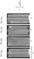
- Figure 11 is a CT image (medical image) of the bone screw 1 inserted into the bone of an animal (pig).
- the bone screw 1 contains a composite mixture in which tantalum, at a concentration of more than 0% but less than or equal to 30% (0%, 10%, 15%, 20%, 25%, 30% by weight), is mixed into a composition containing reinforced fibers.
- Figure 12 is a table evaluating the artifact of the bone screw 1 in the medical image depending on the tantalum content, as shown in Figure 11 .
- the tantalum content in the mixture is 25% or 30% by weight, the artifact evaluation is rated A-, which is acceptable. It is predicted that similar results will occur with other metals (such as titanium, stainless steel, iron, nickel, cobalt, and cemented carbide).
- the bone screw 1 (including at least one of the shaft 2, tip 3, head 4, and thread 5) contains a composite mixture in which metal (such as tantalum, titanium, stainless steel, iron, nickel, cobalt, and cemented carbide) is mixed into a composition containing reinforced fibers at a concentration of more than 0% and less than or equal to 30% by weight (preferably between 10% and 20% by weight, and more preferably between 10% and 15% by weight).
- metal such as tantalum, titanium, stainless steel, iron, nickel, cobalt, and cemented carbide
- the bone screw 1 While reducing the artifact, if at least one of the shaft 2, tip 3, head 4, or thread 5 of the bone screw 1 appears brighter than the surrounding area in a medical image, the bone screw 1 functions as a guide for identifying the position and direction of the bone screw 1 in the medical image.
- the tip 3 may include materials that produce higher brightness in medical images compared to the reinforced fibers 100.
- the tip 3 may include at least one of metal (such as tantalum, titanium, stainless steel, iron, nickel, cobalt, and cemented carbide), ceramic (such as zirconia), cermet, and reinforced fibers of a different composition from the reinforced fiber 100.
- the tip 3 which includes such materials, appears brighter than the surrounding area in a medical image, such as a CT scan, it functions as a guide for identifying the position and direction of the bone screw 1 in the medical image.
- the present invention is useful as a bone screw with sufficient strength.
Landscapes
- Health & Medical Sciences (AREA)
- Orthopedic Medicine & Surgery (AREA)
- Surgery (AREA)
- Life Sciences & Earth Sciences (AREA)
- Engineering & Computer Science (AREA)
- Neurology (AREA)
- Heart & Thoracic Surgery (AREA)
- Biomedical Technology (AREA)
- Nuclear Medicine, Radiotherapy & Molecular Imaging (AREA)
- Medical Informatics (AREA)
- Molecular Biology (AREA)
- Animal Behavior & Ethology (AREA)
- General Health & Medical Sciences (AREA)
- Public Health (AREA)
- Veterinary Medicine (AREA)
- General Engineering & Computer Science (AREA)
- Mechanical Engineering (AREA)
- Surgical Instruments (AREA)
Applications Claiming Priority (2)
| Application Number | Priority Date | Filing Date | Title |
|---|---|---|---|
| JP2022121944 | 2022-07-29 | ||
| PCT/JP2023/025979 WO2024024533A1 (ja) | 2022-07-29 | 2023-07-14 | 骨螺子 |
Publications (1)
| Publication Number | Publication Date |
|---|---|
| EP4563830A1 true EP4563830A1 (en) | 2025-06-04 |
Family
ID=89706312
Family Applications (1)
| Application Number | Title | Priority Date | Filing Date |
|---|---|---|---|
| EP23846264.2A Pending EP4563830A1 (en) | 2022-07-29 | 2023-07-14 | Bone screw |
Country Status (6)
| Country | Link |
|---|---|
| US (1) | US20250160915A1 (https=) |
| EP (1) | EP4563830A1 (https=) |
| JP (1) | JPWO2024024533A1 (https=) |
| KR (1) | KR20250024085A (https=) |
| CN (1) | CN119584929A (https=) |
| WO (1) | WO2024024533A1 (https=) |
Family Cites Families (20)
| Publication number | Priority date | Publication date | Assignee | Title |
|---|---|---|---|---|
| US3566262A (en) | 1968-03-18 | 1971-02-23 | Ibm | Molecular spectrometer using point tunneling |
| JPH0450001A (ja) * | 1990-06-20 | 1992-02-19 | Koya Kensetsu Kogyo:Yugen | 自動車の車輪のスリップ防止装置 |
| US5120171A (en) * | 1990-11-27 | 1992-06-09 | Stuart Surgical | Bone screw with improved threads |
| ES2125329T3 (es) * | 1992-02-14 | 1999-03-01 | Smith & Nephew Inc | Tornillos de materiales polimeros y recubrimientos para usos quirurgicos. |
| US5871486A (en) * | 1993-01-21 | 1999-02-16 | Acumed, Inc. | Variable pitch bone screw |
| WO1996009014A1 (en) * | 1994-09-20 | 1996-03-28 | Smith & Nephew Richards, Inc. | Composite threaded component and method of manufacture |
| HU221524B (hu) * | 1994-12-19 | 2002-11-28 | Sepitec Foundation | Eljárás szerkezeti elem előállítására szálerősítésű, hőre lágyuló műanyagból |
| US8070785B2 (en) * | 2003-09-16 | 2011-12-06 | Spineco, Inc. | Bone anchor prosthesis and system |
| US8628581B2 (en) * | 2004-02-11 | 2014-01-14 | Osteomed Llc | Conical, threaded subtalar implant |
| EP2198796A1 (de) * | 2008-12-19 | 2010-06-23 | Sepitec Foundation | Knochenschraube |
| WO2010091704A1 (en) * | 2009-02-16 | 2010-08-19 | Bayer International Sa | A compound material comprising a metal and nano particles and a method for producing the same |
| EP2737865B1 (en) * | 2010-01-08 | 2016-04-20 | Biedermann Technologies GmbH & Co. KG | Bone screw |
| US10154867B2 (en) * | 2010-06-07 | 2018-12-18 | Carbofix In Orthopedics Llc | Multi-layer composite material bone screw |
| US20140277190A1 (en) * | 2013-03-14 | 2014-09-18 | Howmedica Osteonics Corp. | Compression screw with variable pitch thread |
| JP2014037893A (ja) * | 2013-11-29 | 2014-02-27 | Nitto Seiko Co Ltd | ねじ部品 |
| US10617458B2 (en) * | 2015-12-23 | 2020-04-14 | Carbofix In Orthopedics Llc | Multi-layer composite material bone screw |
| SG11201912595WA (en) * | 2017-09-07 | 2020-01-30 | Ossio Ltd | Fiber reinforced biocomposite threaded implants |
| JP7236725B2 (ja) * | 2018-01-11 | 2023-03-10 | 株式会社タカイコーポレーション | 繊維強化樹脂製ボルト製造方法及び繊維強化樹脂製ボルト |
| JP7316123B2 (ja) * | 2019-07-08 | 2023-07-27 | 中島特殊鋼株式会社 | ボルトおよびナット |
| CN111729134A (zh) * | 2020-08-07 | 2020-10-02 | 沈皆乐 | 用热流铸模制造含碳纤维长丝的peek骨骼固定件的方法 |
-
2023
- 2023-07-14 KR KR1020257001658A patent/KR20250024085A/ko active Pending
- 2023-07-14 CN CN202380054286.9A patent/CN119584929A/zh active Pending
- 2023-07-14 EP EP23846264.2A patent/EP4563830A1/en active Pending
- 2023-07-14 JP JP2024536967A patent/JPWO2024024533A1/ja active Pending
- 2023-07-14 WO PCT/JP2023/025979 patent/WO2024024533A1/ja not_active Ceased
-
2025
- 2025-01-23 US US19/035,357 patent/US20250160915A1/en active Pending
Also Published As
| Publication number | Publication date |
|---|---|
| KR20250024085A (ko) | 2025-02-18 |
| CN119584929A (zh) | 2025-03-07 |
| JPWO2024024533A1 (https=) | 2024-02-01 |
| WO2024024533A1 (ja) | 2024-02-01 |
| US20250160915A1 (en) | 2025-05-22 |
Similar Documents
| Publication | Publication Date | Title |
|---|---|---|
| EP3689259A1 (en) | Suture anchor assemblies | |
| US6508820B2 (en) | Intramedullary interlock screw | |
| AU2013266015B2 (en) | Bone fixation device | |
| US8267978B2 (en) | Hybrid bone fixation apparatus | |
| US9526549B2 (en) | Bone screw with insert | |
| US10271882B2 (en) | Bone screw | |
| EP2233095A1 (en) | Multi-thread bone screw | |
| EP2614787A1 (en) | Multi-axial bone plate fixation | |
| US11253304B2 (en) | Hybrid cannulated orthopedic screws | |
| US20130218214A1 (en) | Bone screw head design | |
| EP0195455A1 (en) | Cranial screw | |
| CA2756748A1 (en) | Locking spiral anchoring means | |
| KR20100055462A (ko) | 나사산 형성 패스너 | |
| US8403973B2 (en) | Pedicle screw assembly having a retractable screw tip for facilitating the securement of the pedicle screw assembly to a spinal vertebra | |
| EP1797828A1 (en) | Threaded suture anchor with starting pitch | |
| EP4563830A1 (en) | Bone screw | |
| US20070156154A1 (en) | Locking Screw | |
| CA2574838C (en) | Screw | |
| JP7750240B2 (ja) | 橈骨固定プレート | |
| US12349951B2 (en) | Double helix bone screw | |
| JPWO2020097482A5 (https=) | ||
| US20250064495A1 (en) | Bone anchor | |
| JP7854148B2 (ja) | ヘッドピン | |
| EP4082458A1 (en) | Bone screw | |
| CN118434382A (zh) | 头针 |
Legal Events
| Date | Code | Title | Description |
|---|---|---|---|
| STAA | Information on the status of an ep patent application or granted ep patent |
Free format text: STATUS: THE INTERNATIONAL PUBLICATION HAS BEEN MADE |
|
| PUAI | Public reference made under article 153(3) epc to a published international application that has entered the european phase |
Free format text: ORIGINAL CODE: 0009012 |
|
| STAA | Information on the status of an ep patent application or granted ep patent |
Free format text: STATUS: REQUEST FOR EXAMINATION WAS MADE |
|
| 17P | Request for examination filed |
Effective date: 20250123 |
|
| AK | Designated contracting states |
Kind code of ref document: A1 Designated state(s): AL AT BE BG CH CY CZ DE DK EE ES FI FR GB GR HR HU IE IS IT LI LT LU LV MC ME MK MT NL NO PL PT RO RS SE SI SK SM TR |
|
| DAV | Request for validation of the european patent (deleted) | ||
| DAX | Request for extension of the european patent (deleted) | ||
| RAP3 | Party data changed (applicant data changed or rights of an application transferred) |
Owner name: SPINE-TECH INC. Owner name: TAKAI CORPORATION |