EP4563745A1 - Track work with the help of a robotic arm and cardan shaft - Google Patents
Track work with the help of a robotic arm and cardan shaft Download PDFInfo
- Publication number
- EP4563745A1 EP4563745A1 EP24208808.6A EP24208808A EP4563745A1 EP 4563745 A1 EP4563745 A1 EP 4563745A1 EP 24208808 A EP24208808 A EP 24208808A EP 4563745 A1 EP4563745 A1 EP 4563745A1
- Authority
- EP
- European Patent Office
- Prior art keywords
- rail vehicle
- railway
- rail
- drive motor
- vehicle
- Prior art date
- Legal status (The legal status is an assumption and is not a legal conclusion. Google has not performed a legal analysis and makes no representation as to the accuracy of the status listed.)
- Pending
Links
Images




Classifications
-
- E—FIXED CONSTRUCTIONS
- E01—CONSTRUCTION OF ROADS, RAILWAYS, OR BRIDGES
- E01B—PERMANENT WAY; PERMANENT-WAY TOOLS; MACHINES FOR MAKING RAILWAYS OF ALL KINDS
- E01B29/00—Laying, rebuilding, or taking-up tracks; Tools or machines therefor
- E01B29/24—Fixing or removing detachable fastening means or accessories thereof; Pre-assembling track components by detachable fastening means
- E01B29/28—Fixing or removing detachable fastening means or accessories thereof; Pre-assembling track components by detachable fastening means the fastening means being of screw-and-nut type; Apparatus therefor, adapted to additionally drilling holes
-
- B—PERFORMING OPERATIONS; TRANSPORTING
- B61—RAILWAYS
- B61D—BODY DETAILS OR KINDS OF RAILWAY VEHICLES
- B61D15/00—Other railway vehicles, e.g. scaffold cars; Adaptations of vehicles for use on railways
Definitions
- the invention relates to a railway vehicle and method for carrying out work on a section of a railway.
- the work may relate to maintenance or new construction.
- the railway vehicle comprises a chassis frame which is equipped with flanged rollers for driving over the two parallel rails of a railway.
- the railway vehicle is equipped with a working device for working on the track structure, for example for tightening and loosening bolts and screws using a motor-driven screw tool, such as a so-called collar screw machine, for example of the rail mounting, such as the spring clamps, on the sleepers.
- the railway is preferably the public civil railway network and/or intended for passenger and freight transport, such as a train, tram or metro line, preferably with an overhead line above the track for the electrical supply of the train locomotive.
- a manually operated device in which the motor-driven working tools are used for the mounting of spring clamps.
- the machine is moved to the next sleeper by pushing against the handles using human muscle power, while driving over the track, while the track worker walks behind it.
- This work device must have sufficient performance, low energy consumption, manageability, limited weight, good balancing, low centre of gravity, reproducible tightening force for the nuts or screws.
- New construction or technical maintenance in particular in the case of railways, outdoors or in an uncontrolled environment such as the space of railway tunnels, requires the use of powerful working devices that can perform various operations, such as drilling, sawing, machining by sanding (grinding), screwing, moving heavy objects or applying mechanical shocks. These working devices must be movable.
- powerful working devices for new construction or maintenance which are also suitable for robotisation, so that people are freed from heavy and monotonous work under difficult working and weather conditions.
- the aim of the invention is to develop a railway vehicle with a working device with a working tool with a, preferably electric, drive motor, for example with which screws, nuts and bolts can be screwed in or out reliably and effectively as much as possible, preferably fully, mechanised, in railway applications, whereby the working device is lightweight and delivers high performance with the desired long-term use, is specifically aimed at the various applications and is constructed safely and reliably with a long service life, low weight, high reliability, low maintenance costs.
- the use of a person is limited as much as possible, preferably completely, to controlling and monitoring functions.
- a further aim of the invention is that the tightening torque supplied can be supplied accurately and reproducibly in order to be able to guarantee the reliability of the mechanical connection thus realised.
- a railway vehicle with a working device which working device is equipped with a working tool and associated, preferably electric, drive motor, a robot arm for manipulating the working tool, and a flexible coupling, such as a telescopic cardan shaft, with which the input shaft of a working tool is drivingly coupled to the output shaft of the drive motor.
- the function of the robot arm can thus be limited to holding and spatially positioning the working tool, and can therefore be constructed in a light weight.
- the working tool can, thanks to the telescopic cardan shaft, be positioned freely in space by the robot arm.
- the working device preferably has one or more of the following:
- the rail vehicle preferably provides one or more of the following:
- the rail vehicle preferably has a forward speed, for example of at least 5 or 10 or 30 or 100 metres per hour and/or a maximum of 0.5 or 1 or 5 or 10 kilometres per hour, continuously, while the number of track components is treated successively.
- the sequence of the axes of movement, seen along the length of the robot arm is as follows: S, L, U, R, B, T.
- the rail vehicle shown in the drawing is, for example, of the type as disclosed in DE 20 2004 013 732 U or NL1028854C2 or EP3078774A1 .
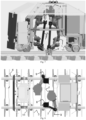
- the rail vehicle is shown in half lengthwise in Fig. 1-5 and in its entirety in Fig. 6-7 , and parts of the side wall have been removed to provide a better view of the working device.
- a working device fixed to the chassis frame with a high-power electric drive motor 8, a telescopic cardan shaft 7, a working tool 9 and a robot arm 1.
- This working device is designed for mounting rail clamps, with which rails and sleepers of a track are connected to each other.
- the rail vehicle has a chassis frame that stands on the two rails 4 with flanged rollers 11.
- the telescopic cardan shaft is cardanically connected to the working tool at one end at a distance from the drive motor.
- FIG. 11 The railway of Fig. 11 is electrified, therefore there are portals (one of which is visible) along it, which carry the contact wire.
- Fig. 12 shows how the portal leg 6 is founded by a steel-founded prefabricated element 5 next to or in the edge area of the ballast bed 2 which carries the sleepers 3 with the rails 4 on them.
Landscapes
- Engineering & Computer Science (AREA)
- Transportation (AREA)
- Mechanical Engineering (AREA)
- Architecture (AREA)
- Civil Engineering (AREA)
- Structural Engineering (AREA)
- Machines For Laying And Maintaining Railways (AREA)
- Manipulator (AREA)
Abstract
Rail vehicle for carrying out work on a section of a railway, the work may relate to maintenance or new construction, the rail vehicle comprises a chassis frame which is equipped with flange rollers for driving over the two parallel rails of a railway, the rail vehicle delimits an internal work space, preferably open towards the bottom, which is equipped with a work device for working on the track structure, for example under the rail vehicle, for example for tightening and loosening spring clamps.
Description
- The invention relates to a railway vehicle and method for carrying out work on a section of a railway. The work may relate to maintenance or new construction. The railway vehicle comprises a chassis frame which is equipped with flanged rollers for driving over the two parallel rails of a railway. The railway vehicle is equipped with a working device for working on the track structure, for example for tightening and loosening bolts and screws using a motor-driven screw tool, such as a so-called collar screw machine, for example of the rail mounting, such as the spring clamps, on the sleepers. The railway is preferably the public civil railway network and/or intended for passenger and freight transport, such as a train, tram or metro line, preferably with an overhead line above the track for the electrical supply of the train locomotive.
- From
FR 2 659 674DE 20305569 U1 a manually operated device is known, in which the motor-driven working tools are used for the mounting of spring clamps. During operation, the machine is moved to the next sleeper by pushing against the handles using human muscle power, while driving over the track, while the track worker walks behind it.DE 20 2004 013 732 U discloses a railway vehicle (= mobile workshop) with an internal workspace open at the bottom, located between two side walls that shield the internal workspace from the adjacent environment in order to provide a shielded area within which track workers can work safely. - Other work devices to which the invention may apply are, for example: sleeper drilling machine; rail surface grinding machine; switch grinding machine.
- This work device must have sufficient performance, low energy consumption, manageability, limited weight, good balancing, low centre of gravity, reproducible tightening force for the nuts or screws. New construction or technical maintenance, in particular in the case of railways, outdoors or in an uncontrolled environment such as the space of railway tunnels, requires the use of powerful working devices that can perform various operations, such as drilling, sawing, machining by sanding (grinding), screwing, moving heavy objects or applying mechanical shocks. These working devices must be movable. There is interest in powerful working devices for new construction or maintenance, which are also suitable for robotisation, so that people are freed from heavy and monotonous work under difficult working and weather conditions. The aim of the invention is to develop a railway vehicle with a working device with a working tool with a, preferably electric, drive motor, for example with which screws, nuts and bolts can be screwed in or out reliably and effectively as much as possible, preferably fully, mechanised, in railway applications, whereby the working device is lightweight and delivers high performance with the desired long-term use, is specifically aimed at the various applications and is constructed safely and reliably with a long service life, low weight, high reliability, low maintenance costs. The use of a person is limited as much as possible, preferably completely, to controlling and monitoring functions. In the case where a tightening torque has to be supplied by the work device, for example for tightening screws or bolts, a further aim of the invention is that the tightening torque supplied can be supplied accurately and reproducibly in order to be able to guarantee the reliability of the mechanical connection thus realised.
- The implementation of a simple solution is made more difficult in the case of the use of an industrial robot by a significant increase in the weight of the robot as the forces to be exerted by the robot increase. It is therefore necessary, in a context initially defined for the use of a human worker, to apply means to take this circumstance into account.
- To solve these problems, a railway vehicle with a working device is proposed, which working device is equipped with a working tool and associated, preferably electric, drive motor, a robot arm for manipulating the working tool, and a flexible coupling, such as a telescopic cardan shaft, with which the input shaft of a working tool is drivingly coupled to the output shaft of the drive motor. The function of the robot arm can thus be limited to holding and spatially positioning the working tool, and can therefore be constructed in a light weight. The working tool can, thanks to the telescopic cardan shaft, be positioned freely in space by the robot arm.
- The working device preferably has one or more of the following:
- is mounted to the chassis frame of the rail vehicle;
- is mounted to the side of the central longitudinal axis of the rail vehicle, seen in plan view;
- the telescopic cardan shaft has a cardanic coupling at both ends and a telescopic rod in between that can be extended or shortened by telescoping;
- the telescopic cardan shaft is at one end, at a distance, preferably at least 50 centimetres, from the drive motor, cardanically coupled to the working tool via the cardanic coupling;
- the telescopic cardan shaft is at its other end cardanically coupled to the output shaft of the drive motor via the cardanic coupling;
- the length of the fully retracted cardan shaft is at least 25 or 50 and/or a maximum of 150 centimetres;
- the length of the fully extended cardan shaft is at least 75 and/or a maximum of 250 centimetres; - the work tool is equipped with a device, for example detachable fixing means, such as a clamp, to fix itself to the track structure, for example by clamping to a rail or sleeper or spring clamp;
- the output shaft of the drive motor is oriented vertically;
- the output shaft of the drive motor is located at a level above, preferably at least 25 or 50 centimetres above, the level at which the base of the robot arm is mounted to the rail vehicle;
- the output shaft of the drive motor is located further away, preferably at least 10 or 25 centimetres further away, from the centreline of the rail vehicle and/or the railway than the base of the robot arm, seen in plan view;
- the output shaft of the drive motor is located vertically directly above the straight line connecting the running wheels on the same side of the rail vehicle; - the output shaft of the drive motor is located at a level of at least 25 or 50 or 100 centimetres and/or at most 150 or 200 or 250 centimetres above the level of the bottom of the running wheels of the rail vehicle, in other words the top of the rail head in the event that the running wheel in question rests on the rail head in the typical manner;
- the robot arm and/or drive motor is mounted to the side of the central longitudinal axis of the rail vehicle and/or the railway, viewed in plan view, preferably positioned in the horizontal direction transversely to the central longitudinal axis at a distance, preferably at least 20 or 50 centimetres, from that central longitudinal axis.
- The rail vehicle preferably provides one or more of the following:
- an internal working space open towards the bottom, for example so that the internal working space is provided between two upright side walls of the rail vehicle, from which internal working space access is obtained via the open bottom to the track structure under the rail vehicle;
- a chassis frame formed by tubes or profiles;
- panels fixed to the chassis frame to form walls to form an internal working space protected from the elements;
- the internal working space is essentially a rectangular block with a width of at least 1 or 1.5 metres and a height of at least 1 or 1.5 or 2 or 2.5 metres;
- the internal working space is provided between a front and a rear upright wall;
- the internal working space has a dimension and/or the front and rear upright walls, maintain a distance, measured along the median longitudinal axis of the vehicle and/or the railway, of at least 1 and/or a maximum of 2 or 2.5 or 3 metres;
- designed as a rail/road vehicle;
- light in weight, for example a maximum of 3 or 5 or 10 thousand kilograms to be transported by road as a lorry load.
- For the industrial robot arm, preferably one or more of the following applies:
- of at least 3-axis type, preferably at least or exactly 5-axis or 6-axis type;
- of vertically articulated type;
- contains the following movement axes: S, L, U, R, B, T (see
fig. 6 + 7); - the maximum rotation angle of one or more of the movement axes is at least 90 degrees;
- for one or more of the characteristic dimensions V, W, X, Y, Z (see
fig. 6 ) the following applies (in millimetres): V minimum 455 and/or maximum 555, such as 505 or minimum 490 and/or maximum 590, such as 540, W minimum 180 and/or maximum 220, such as 200 or minimum 190 and/or maximum 230, such as 210, X minimum 700 and/or maximum 820, such as 760 or minimum 810 and/or maximum 930, such as 870, Y minimum 715 and/or maximum 875, such as 795 or minimum 945 and/or maximum 1105, such as 1025, Z minimum 135 and/or maximum 165, such as 150 or minimum 290 and/or maximum 350, such as 320; - mounted with the S-axis, i.e. the axis of movement of the base, horizontal; - mounted with the base or the S-axis, i.e. the axis of movement of the base, at a level at least 25 or 50 centimetres and/or at most 150 or 200 centimetres above the level of the bottom of the running wheels of the rail vehicle, in other words the top of the rail head in the event that the relevant running wheel rests on the rail head in the typical manner.
- While the working device is in operation and successively or one after the other treats a number of, for example, at least 3 or 5 or 10, preferably mutually identical, track components, for example spring clamps, with mutual spacing of preferably at least 10 or 20 centimetres, seen in the longitudinal direction of the railway, or according to the pitch of the sleepers, the rail vehicle preferably has a forward speed, for example of at least 5 or 10 or 30 or 100 metres per hour and/or a maximum of 0.5 or 1 or 5 or 10 kilometres per hour, continuously, while the number of track components is treated successively.
- Preferably, the definition of the axes of movement is: S=rotation of the base; and/or S=the shoulder joint; L= pivoting of the upper arm relative to the base; U=pivoting of the forearm relative to the upper arm; and/or U=elbow joint; R=rolling of the forearm around its longitudinal axis; B=pivoting of the free end and/or B=pivoting of the tool holder relative to the forearm; and/or B=wrist joint; T=rolling of the free end and/or T=rolling of the tool holder around its longitudinal axis.
- Preferably, the sequence of the axes of movement, seen along the length of the robot arm, is as follows: S, L, U, R, B, T.
- Preferably, the definition of the characteristic dimensions is: V=distance between L and the bearing surface of the base of the robot arm; W=distance between U and R; X=distance between L and U; Y=distance between U and B; Z=distance between S and L.
- For the axes of movement, preferably one or more of the following applies for the mutual orientation in all positions of the robot arm: B perpendicular to T; U and L parallel; S perpendicular to L and U; R perpendicular to L and U.
- The invention is further explained below by way of non-limiting embodiments, which are shown in the accompanying drawing, which shows in:
-
Fig. 1-4 an application for mounting or dismounting the rail mounting on the sleepers; -
Fig. 5 an application for drilling holes in the sleepers; -
Fig. 6 a schematic representation; -
Fig. 7-8 an alternative from the side and above -
Fig. 9-10 a side and perspective view of the robot arm type used; -
Fig. 11 a perspective view of a double railway or track; -
Fig. 12 a cross-section of a part of the track offig. 1-5 . - The rail vehicle shown in the drawing is, for example, of the type as disclosed in
DE 20 2004 013 732 U orNL1028854C2 EP3078774A1 . - The rail vehicle is shown in half lengthwise in
Fig. 1-5 and in its entirety inFig. 6-7 , and parts of the side wall have been removed to provide a better view of the working device. - Visible are a working device fixed to the chassis frame with a high-power
electric drive motor 8, atelescopic cardan shaft 7, a workingtool 9 and arobot arm 1. - This working device is designed for mounting rail clamps, with which rails and sleepers of a track are connected to each other. The rail vehicle has a chassis frame that stands on the two
rails 4 withflanged rollers 11. - The telescopic cardan shaft is cardanically connected to the working tool at one end at a distance from the drive motor.
- Explanation of the reference symbols used in
Fig. 9-10 : S-axis rotation of the base (rotation axis is perpendicular to the mounting surface of the base) ; L-axis bending lower arm; U-axis bending upper arm; R-axis rotating upper arm about the longitudinal axis; B-axis wrist bend; T-axis tool coupling rotate about the longitudinal axis. - The railway of
Fig. 11 is electrified, therefore there are portals (one of which is visible) along it, which carry the contact wire.Fig. 12 shows how theportal leg 6 is founded by a steel-foundedprefabricated element 5 next to or in the edge area of theballast bed 2 which carries thesleepers 3 with therails 4 on them. - Features of different embodiments disclosed herein can be combined in different ways and different aspects of features are considered mutually interchangeable. All features described or disclosed in the drawing provide the subject matter of the invention on their own or in any combination, also independently of their place in the claims or their reference.
Claims (11)
- Method for carrying out work on a section of a railway, the work may relate to maintenance or new construction, the railway vehicle contains a chassis frame equipped with flange rollers to drive over the two parallel rails of a railway, the railway vehicle delimits an internal work space, preferably open towards the bottom, which is equipped with a work device to work on the track structure, for example under the railway vehicle, for example for tightening and loosening bolts and screws using a motor-driven screw tool, such as a so-called collar screw machine, for example of the rail mounting, such as the spring clamps, on the sleepers.
- Method according to claim 1, the working device is equipped with the working tool and associated electric drive motor, a robot arm for manipulating the working tool, and a telescopic cardan shaft, with which the input shaft of the working tool is drivingly coupled to the output shaft of the drive motor so that the cardan shaft provides the drive for the working tool for tightening the fastening bolts.
- Method according to claim 1 or 2, the function of the robot arm remains limited during the method to holding and spatially positioning the working tool, and is lightweight.
- Method according to one of claims 1-3, the working tool is positioned freely in space by the robot arm due to the use of the telescopic cardan shaft.
- Method according to one of claims 1-4, one or more of the following applies to the working device:- is mounted on the chassis frame of the rail vehicle;- is mounted to the side of the central longitudinal axis of the rail vehicle, seen in top view;- the telescopic cardan shaft has a cardanic coupling at both ends and a telescopic rod in between that can be lengthened or shortened by telescoping;- the telescopic cardan shaft is at one end, at a distance of at least 50 centimetres from the drive motor, cardanically coupled to the work tool via the cardanic coupling;- the telescopic cardan shaft is at its other end cardanically coupled to the output shaft of the drive motor via the cardanic coupling;- the length of the fully retracted cardan shaft is at least 25 and at most 150 centimetres;- the length of the fully extended cardan shaft is at least 75 and at most 250 centimetres;- the work tool is equipped with a clamp, with which it temporarily fixes itself in relation to the track structure, by clamping itself to a rail;- the output shaft of the drive motor is oriented vertically;- the output shaft of the drive motor is located at a level at least 50 centimetres above the level at which the base of the robot arm is mounted on the rail vehicle;- the output shaft of the drive motor is located at least 25 centimetres further away from the centre longitudinal axis of the rail vehicle and the railway than the base of the robot arm, seen in plan view;- the output shaft of the drive motor is located vertically directly above the straight line connecting the running wheels on the same side of the rail vehicle;- the output shaft of the drive motor is located at a level at least 50 centimetres and at most 200 centimetres above the level of the bottom of the running wheels of the rail vehicle, in other words the top of the rail head in the event that the running wheel in question rests on the rail head in the typical manner;- the robot arm and drive motor are mounted to the side of the centre longitudinal axis of the rail vehicle and the railway, seen in plan view, positioned in the horizontal direction transversely to the centre longitudinal axis at a distance of at least 50 centimetres from that centre longitudinal axis.
- Method according to any of claims 1-5, the rail vehicle provides one or more of the following:- a downwardly open internal working space, so that the internal working space is provided between two upright side walls of the rail vehicle, from which internal working space access is obtained via the open underside to the track structure under the rail vehicle;- a chassis frame formed by profiles;- panels attached to the chassis frame for forming walls to form an internal working space shielded from the weather;- the internal working space is a rectangular block with a width of at least 1.5 metres and a height of at least 2 metres;- the internal working space is provided between a front and a rear upright wall;- the front and rear upright walls maintain a distance, measured along the centre longitudinal axis of the vehicle, of at least 1 and at most 3 metres;- designed as a rail/road vehicle;- light in weight, maximum 5 thousand kilograms to be able to be transported on the road as a load from a lorry
- Method according to any one of claims 1 to 6, for the industrial robot arm one or more of the following applies:- of precisely 6-axis type;- of vertically articulated type;- contains the following axes of movement: S, L, U, R, B, T (see fig. 6 + 7);- the maximum rotation angle of all six axes of movement is at least 90 degrees;- for the characteristic dimensions V, W, X, Y, Z (see fig. 6) the following applies (in millimeters): V at least 490 and at most 590, W at least 190 and 230, X at least 810 and at most 930, Y at least 945 and at most 1105, Z at least 290 and at most 350;- mounted with the S-axis, i.e. the axis of movement of the base, horizontal; - mounted with the base or the S-axis, i.e. the axis of movement of the base, at a level at least 50 centimetres and at most 200 centimetres above the level of the bottom of the running wheels of the rail vehicle, in other words the top of the rail head in the event that the running wheel in question rests on the rail head in the typical manner.
- Method according to any one of claims 1 to 7, while the working device is in operation and of a number of, for example, at least 10 mutually identical spring clamps, with mutual spacing according to the pitch of the sleepers and directly following each other, viewed in the longitudinal direction of the railway, tightens the fastening bolts by means of the working tool which is held and spatially positioned by the robot arm and driven by the cardan shaft, the railway vehicle moving over the track has a continuous forward speed of, for example, at least 100 metres per hour, while the working tool, by manipulation with the robot arm, in the meantime carries out a movement cycle with respect to the railway vehicle of first moving forward, with a forward speed higher than that of the railway vehicle, to the next fastening bolt and engaging it and then moving backwards while engaging and remaining in the same location with respect to the fastening bolt, until the fastening bolt has been sufficiently tightened and then again forward movement, at a forward speed higher than that of the rail vehicle, to the next attachment bolt of the number.
- Method according to one of claims 1-10, the rail vehicle is non-articulated.
- Rail vehicle for carrying out the method according to one of claims 1-9.
- Rail vehicle according to claim 10, with one or more of the design features according to one of claims 1-9.
Applications Claiming Priority (2)
| Application Number | Priority Date | Filing Date | Title |
|---|---|---|---|
| NL2036109A NL2036109B1 (en) | 2023-10-24 | 2023-10-24 | TRACK WORK WITH THE HELP OF A ROBOTIC ARM AND CARDAN SHAFT |
| NL2040242A NL2040242A (en) | 2023-10-24 | 2023-10-24 | TRACK WORK USING A ROBOTIC ARM AND CARD SHAFT |
Publications (1)
| Publication Number | Publication Date |
|---|---|
| EP4563745A1 true EP4563745A1 (en) | 2025-06-04 |
Family
ID=95605189
Family Applications (1)
| Application Number | Title | Priority Date | Filing Date |
|---|---|---|---|
| EP24208808.6A Pending EP4563745A1 (en) | 2023-10-24 | 2024-10-24 | Track work with the help of a robotic arm and cardan shaft |
Country Status (2)
| Country | Link |
|---|---|
| EP (1) | EP4563745A1 (en) |
| NL (3) | NL2036109B1 (en) |
Citations (9)
| Publication number | Priority date | Publication date | Assignee | Title |
|---|---|---|---|---|
| DE1085182B (en) * | 1957-07-22 | 1960-07-14 | Matisa Materiel Ind Sa | Machine that can be driven on a railway track to screw in and out sleeper screws |
| DE2211606A1 (en) * | 1972-03-10 | 1973-09-20 | Robel & Co G | SCREWING DEVICE FOR RAIL FASTENERS |
| SU1193201A1 (en) * | 1984-06-21 | 1985-11-23 | Sp K B Polimernogo Mash Ki Pro | Apparatus for screwing and unscrewing nuts of rail joint |
| FR2659674A1 (en) | 1990-03-19 | 1991-09-20 | Geismar Anc Ets L | Machine for fitting and extracting attachment members, especially members for attaching rails to the sleepers of a railway track |
| DE20305569U1 (en) | 2003-04-07 | 2003-06-18 | ROBEL Bahnbaumaschinen GmbH, 83395 Freilassing | Device for mounting a rail clamp connecting a rail to sleeper of track comprises an aggregate frame mounted on a chassis with tool positioned in working position and elastic pressure element acting against movement of pressing elements |
| DE202004013732U1 (en) | 2004-09-03 | 2004-12-16 | Robel Bahnbaumaschinen Gmbh | maintenance vehicle |
| NL1028854C2 (en) | 2005-04-24 | 2006-10-27 | Movares Nederland Bv | Railway vehicle for track maintenance work, has enclosed workspace with openable roof |
| EP3078774A1 (en) | 2015-04-07 | 2016-10-12 | VolkerRail Nederland BV | Mobile robot station and repair method |
| WO2017121441A1 (en) * | 2016-01-14 | 2017-07-20 | Robel Bahnbaumaschinen Gmbh | Maintenance vehicle and method |
Family Cites Families (1)
| Publication number | Priority date | Publication date | Assignee | Title |
|---|---|---|---|---|
| DE102020207437A1 (en) * | 2020-06-16 | 2021-12-16 | Robel Bahnbaumaschinen Gmbh | Device for track processing |
-
2023
- 2023-10-24 NL NL2036109A patent/NL2036109B1/en active
- 2023-10-24 NL NL2040242A patent/NL2040242A/en unknown
-
2024
- 2024-10-24 EP EP24208808.6A patent/EP4563745A1/en active Pending
-
2026
- 2026-01-12 NL NL4000762A patent/NL4000762A/en unknown
Patent Citations (9)
| Publication number | Priority date | Publication date | Assignee | Title |
|---|---|---|---|---|
| DE1085182B (en) * | 1957-07-22 | 1960-07-14 | Matisa Materiel Ind Sa | Machine that can be driven on a railway track to screw in and out sleeper screws |
| DE2211606A1 (en) * | 1972-03-10 | 1973-09-20 | Robel & Co G | SCREWING DEVICE FOR RAIL FASTENERS |
| SU1193201A1 (en) * | 1984-06-21 | 1985-11-23 | Sp K B Polimernogo Mash Ki Pro | Apparatus for screwing and unscrewing nuts of rail joint |
| FR2659674A1 (en) | 1990-03-19 | 1991-09-20 | Geismar Anc Ets L | Machine for fitting and extracting attachment members, especially members for attaching rails to the sleepers of a railway track |
| DE20305569U1 (en) | 2003-04-07 | 2003-06-18 | ROBEL Bahnbaumaschinen GmbH, 83395 Freilassing | Device for mounting a rail clamp connecting a rail to sleeper of track comprises an aggregate frame mounted on a chassis with tool positioned in working position and elastic pressure element acting against movement of pressing elements |
| DE202004013732U1 (en) | 2004-09-03 | 2004-12-16 | Robel Bahnbaumaschinen Gmbh | maintenance vehicle |
| NL1028854C2 (en) | 2005-04-24 | 2006-10-27 | Movares Nederland Bv | Railway vehicle for track maintenance work, has enclosed workspace with openable roof |
| EP3078774A1 (en) | 2015-04-07 | 2016-10-12 | VolkerRail Nederland BV | Mobile robot station and repair method |
| WO2017121441A1 (en) * | 2016-01-14 | 2017-07-20 | Robel Bahnbaumaschinen Gmbh | Maintenance vehicle and method |
Also Published As
| Publication number | Publication date |
|---|---|
| NL4000762A (en) | 2026-04-28 |
| NL2036109B1 (en) | 2025-05-06 |
| NL2040242A (en) | 2025-07-01 |
Similar Documents
| Publication | Publication Date | Title |
|---|---|---|
| CN103972821B (en) | High voltage transmission line live work robot | |
| CN111906801B (en) | A robot flexible unit for contact network wrist arm pipe clamping | |
| RU2105835C1 (en) | Machine for track-laying operations | |
| JP5332042B2 (en) | Track maintenance device and track maintenance system | |
| AU2011349102B2 (en) | Apparatus for the application or removal of railway track fasteners | |
| CN115596478B (en) | Roughening device for repairing operated tunnel defect | |
| CN212241079U (en) | Robot flexible unit for clamping contact network cantilever pipe fitting | |
| CN110445053A (en) | A vibration-proof hammer maintenance robot and its maintenance method for four-split ultra-high voltage transmission wires | |
| NL2036109B1 (en) | TRACK WORK WITH THE HELP OF A ROBOTIC ARM AND CARDAN SHAFT | |
| EP4545705A1 (en) | Track work with the help of two or three robotic arms | |
| CN111622030B (en) | Auxiliary cold disassembling equipment for railway glued insulating joint | |
| JPH06117198A (en) | Segment re-tightening device for shield tunnel | |
| JP6139738B1 (en) | Work truck for attaching and detaching connecting devices for railway vehicles | |
| CN211112959U (en) | Self-propelled rail bolt tightening and loosening device | |
| JPH05611A (en) | Track work vehicle | |
| NL4000760A (en) | TRACK WORK WITH THE ASSISTANCE OF TWO OR THREE ROBOT ARMS | |
| CN224254676U (en) | Mine car wheel set dismounting tool | |
| CN119794754B (en) | A track disassembly platform for armored equipment | |
| CN218756809U (en) | Utilize two emery wheels to carry out processingequipment that two were ground | |
| CN220613879U (en) | An efficient railway maintenance bolt tightening device | |
| CN224016045U (en) | Quick replacement device for railway steel bridge sleeper | |
| CN111485459A (en) | Electric flexible shaft tamping tool | |
| CN209919876U (en) | Track mounting structure of inspection robot | |
| CN209919878U (en) | Mounting structure of inspection robot | |
| CN212265983U (en) | Material cutting device for municipal construction |
Legal Events
| Date | Code | Title | Description |
|---|---|---|---|
| PUAI | Public reference made under article 153(3) epc to a published international application that has entered the european phase |
Free format text: ORIGINAL CODE: 0009012 |
|
| STAA | Information on the status of an ep patent application or granted ep patent |
Free format text: STATUS: THE APPLICATION HAS BEEN PUBLISHED |
|
| AK | Designated contracting states |
Kind code of ref document: A1 Designated state(s): AL AT BE BG CH CY CZ DE DK EE ES FI FR GB GR HR HU IE IS IT LI LT LU LV MC ME MK MT NL NO PL PT RO RS SE SI SK SM TR |
|
| STAA | Information on the status of an ep patent application or granted ep patent |
Free format text: STATUS: REQUEST FOR EXAMINATION WAS MADE |
|
| 17P | Request for examination filed |
Effective date: 20251203 |
|
| STAA | Information on the status of an ep patent application or granted ep patent |
Free format text: STATUS: EXAMINATION IS IN PROGRESS |