EP4563286A2 - Rotary installation tools for clinch fasteners - Google Patents
Rotary installation tools for clinch fasteners Download PDFInfo
- Publication number
- EP4563286A2 EP4563286A2 EP25170594.3A EP25170594A EP4563286A2 EP 4563286 A2 EP4563286 A2 EP 4563286A2 EP 25170594 A EP25170594 A EP 25170594A EP 4563286 A2 EP4563286 A2 EP 4563286A2
- Authority
- EP
- European Patent Office
- Prior art keywords
- displacer
- tool
- workpiece
- displacers
- fastener
- Prior art date
- Legal status (The legal status is an assumption and is not a legal conclusion. Google has not performed a legal analysis and makes no representation as to the accuracy of the status listed.)
- Pending
Links
Images


Classifications
-
- B—PERFORMING OPERATIONS; TRANSPORTING
- B21—MECHANICAL METAL-WORKING WITHOUT ESSENTIALLY REMOVING MATERIAL; PUNCHING METAL
- B21K—MAKING FORGED OR PRESSED METAL PRODUCTS, e.g. HORSE-SHOES, RIVETS, BOLTS OR WHEELS
- B21K25/00—Uniting components to form integral members, e.g. turbine wheels and shafts, caulks with inserts, with or without shaping of the components
-
- B—PERFORMING OPERATIONS; TRANSPORTING
- B23—MACHINE TOOLS; METAL-WORKING NOT OTHERWISE PROVIDED FOR
- B23P—METAL-WORKING NOT OTHERWISE PROVIDED FOR; COMBINED OPERATIONS; UNIVERSAL MACHINE TOOLS
- B23P11/00—Connecting or disconnecting metal parts or objects by metal-working techniques not otherwise provided for
- B23P11/005—Connecting or disconnecting metal parts or objects by metal-working techniques not otherwise provided for by expanding or crimping
-
- B—PERFORMING OPERATIONS; TRANSPORTING
- B23—MACHINE TOOLS; METAL-WORKING NOT OTHERWISE PROVIDED FOR
- B23P—METAL-WORKING NOT OTHERWISE PROVIDED FOR; COMBINED OPERATIONS; UNIVERSAL MACHINE TOOLS
- B23P19/00—Machines for simply fitting together or separating metal parts or objects, or metal and non-metal parts, whether or not involving some deformation; Tools or devices therefor so far as not provided for in other classes
- B23P19/04—Machines for simply fitting together or separating metal parts or objects, or metal and non-metal parts, whether or not involving some deformation; Tools or devices therefor so far as not provided for in other classes for assembling or disassembling parts
- B23P19/06—Screw or nut setting or loosening machines
- B23P19/062—Pierce nut setting machines
- B23P19/064—Deforming the support material only, e.g. the sheet or plate
-
- B—PERFORMING OPERATIONS; TRANSPORTING
- B25—HAND TOOLS; PORTABLE POWER-DRIVEN TOOLS; MANIPULATORS
- B25B—TOOLS OR BENCH DEVICES NOT OTHERWISE PROVIDED FOR, FOR FASTENING, CONNECTING, DISENGAGING OR HOLDING
- B25B27/00—Hand tools, specially adapted for fitting together or separating parts or objects whether or not involving some deformation, not otherwise provided for
- B25B27/0007—Tools for fixing internally screw-threaded tubular fasteners
-
- F—MECHANICAL ENGINEERING; LIGHTING; HEATING; WEAPONS; BLASTING
- F16—ENGINEERING ELEMENTS AND UNITS; GENERAL MEASURES FOR PRODUCING AND MAINTAINING EFFECTIVE FUNCTIONING OF MACHINES OR INSTALLATIONS; THERMAL INSULATION IN GENERAL
- F16B—DEVICES FOR FASTENING OR SECURING CONSTRUCTIONAL ELEMENTS OR MACHINE PARTS TOGETHER, e.g. NAILS, BOLTS, CIRCLIPS, CLAMPS, CLIPS OR WEDGES; JOINTS OR JOINTING
- F16B37/00—Nuts or like thread-engaging members
- F16B37/04—Devices for fastening nuts to surfaces, e.g. sheets, plates
- F16B37/06—Devices for fastening nuts to surfaces, e.g. sheets, plates by means of welding or riveting
- F16B37/062—Devices for fastening nuts to surfaces, e.g. sheets, plates by means of welding or riveting by means of riveting
- F16B37/068—Devices for fastening nuts to surfaces, e.g. sheets, plates by means of welding or riveting by means of riveting by deforming the material of the support, e.g. the sheet or plate
-
- Y—GENERAL TAGGING OF NEW TECHNOLOGICAL DEVELOPMENTS; GENERAL TAGGING OF CROSS-SECTIONAL TECHNOLOGIES SPANNING OVER SEVERAL SECTIONS OF THE IPC; TECHNICAL SUBJECTS COVERED BY FORMER USPC CROSS-REFERENCE ART COLLECTIONS [XRACs] AND DIGESTS
- Y10—TECHNICAL SUBJECTS COVERED BY FORMER USPC
- Y10T—TECHNICAL SUBJECTS COVERED BY FORMER US CLASSIFICATION
- Y10T29/00—Metal working
- Y10T29/49—Method of mechanical manufacture
- Y10T29/49826—Assembling or joining
- Y10T29/49908—Joining by deforming
- Y10T29/49915—Overedge assembling of seated part
Definitions
- the present invention relates to the installation of clinch fasteners into a sheet or panel workpiece by use of a rotary press which imparts both rotation and pressing force to the workpiece to achieve attachment of the fastener to the workpiece.
- Rotary installation displacers can be radial wedges which push and pull metal from the surface of an installation panel, around the base of a clinch fastener. This method greatly reduces the installation force, and consequently the axial compressive stresses, that can cause an undesirable cosmetic mark on the opposite side of the panel from the installation.
- the tooling devised is held within the nose of a rotary punch and as the tool is rotated and forced against a workpiece, usually a malleable panel composed of a metal such as aluminum. During the installation process the panel is non-destructively deformed around a fastener held within the tool to affix the fastener to the workpiece.
- the workpiece panel metal is reshaped without any loss of material.
- Rotary installation utilizes a reduced area displacers to reduce the axial installation force by converting much of the installation force to installation torque.
- Five different types of displacers are possible to accomplish the goal of rotary installation of a fastener that are described in the drawings and embodiments described below, namely:
- the installation tool of the invention comprises a rotary punch press tip which holds a fastener.
- the tip has displacers which contact a receiving workpiece such as a metal panel to force material of the panel onto a flange of the fastener to attach it. Tips vary in the different types of displacers that they employ. The following four displacer embodiments are illustrated and discussed below. Herein the replaceable tips are also referred to as the "tools".
- profile means the three-dimensional configuration of a displacer.
- Figure 1 depicts one embodiment of a displacer tool 10 according to the invention intended for use in a standard CNC machine which applies both pressing and rotational forces to the punch fixture 12 such as seen in figure 2 .
- a complete description of a punch of this type is disclosed in pending co-owned US patent application 16/307, 133 which is incorporated herein by reference as though fully set forth.
- fasteners can be affixed to malleable metal panels. In all of these embodiments the panels are prepared with blind receiving holes.
- the main elements of the tool tip are a body 14 with attachment means 13 for being held within a rotary punch press fixture 12 as seen in Figure 2 .
- the working end of the tool has a flange 15 with an end face that has a plurality of displacers such as those shown at 16a,b,and c which surround a central bore 17 that holds the fastener while it is being installed.
- the tool is pressed to a given point and the tool is then rotated at that depth.
- Three separate displacers are shown, each with a different profile that acts upon the workpiece panel as the tool is rotated.
- Displacer 16a has a ramped profile that parts off the outside diameter of the metal which is pulled in and moves partially toward outside diameter of the fastener being installed. Its profile is vertically tapered along an arcuate ridge centered about the axial bore from a back end of the displacer of greatest height down to a front end of minimum height of the displacer where the ridge meets the end face. Displacer 16b, is like an additional snow plow that follows after the first displacer and has a configuration that moves the parted metal even closer to the outside periphery of the fastener being installed. And finally, displacer 16c, having a profile rectangular in section, then compresses the peak of displaced material to press the metal tightly down around the fastener.
- these displacers illustrate how different displacers while operating independently function together to form the desired sequential composite displacement of workpiece material 21.
- the panel material is reshaped around and above the outside of a flange 23 of fastener 25 which has been inserted into a blind hole of the receiving panel 24.
- the workpiece panel is cut into and deformed without any loss of panel material.
- rolling balls 41 are employed in a tool tip 40 to displace the panel material.
- panel material is moved by a continuous displacement method by a displacer ring 71 that wobbles.
- the displacer ring is loosely fitting to the tool body both radially and axially by attachment means 76 at the top to allow it to tip to one side or the other as the body is rotated.
- the displacer ring also has a raceway on which a single ball bearing 73 can travel which further functions to retain the ball 73 within the tool assembly.
- the displacer ring has a conical profile with a circular cutting edge 74. This displacer applies force to one portion of a full circle displacer through the single ball bearing 73 captivated to the tool body.
- the displacer ring wobbles.
- the displacement force is applied following the ball bearing around the circumference of the installation causing the displacer to wobble, and thus pressing only a portion of the displacer ring cutting edge at point 75 into the panel at any one point in time.
- Unlike multiple displacers which are all pressed into the panel together equally, only a small portion of this displacer is pressed in small increments as the tip is rotated. Since only a small portion of the displacer is being pressed at any given time throughout the installation period, the installation force is greatly reduced. There is no sliding or rolling friction between the panel and displacer, and as such torsional stresses are greatly reduced.
- Figure 8 depicts another embodiment which utilizes an incremental displacer similar to that shown in Figure 7 .
- This displacer substitutes the ball and raceway structures of Figure 7 with a cone gear 82 meshed with two circular cone racks 84 and 85, one above and one below.
- the incorporation of a spring 87 is also added to illustrate how stability to the displacer tip can be added when and if necessary.
- the cone gear guarantees no slipping between the gear faces and consequently ensures s full 360 degrees of pressing per rotation of the tool body.
- incremental displacement of panel material is achieved using an oscillation method with individual displacers.
- oscillation is used to describe the axial up and down stroking motion of the tool during the installation process, the downward motion referring to the as the advance of the tool toward the workpiece.
- stroke means a cyclical downward and then upward motion of the tool returning it to its starting position.
- displacers 94 are machined and polished rounded surfaces or rounded fixed pins forming a unitary part of the tool body 92.
- the displacers shown are spherical at any point where they can contact the panel 98 as seen in Figure 10 .
- Displacer geometry can also be wedge-shaped as in previous embodiments of this design.
- the tool body and displacers seen in figure 10 are unified in one solid machined body.
- the tool is incrementally stroked, and rotated between strokes of a given length which results in a workpiece deformation to a predetermined depth level.
- the tool is rotated a set amount (e.g. 20°) before the next stroke is applied. Installation is achieved in incrementally advancing displacement depth levels. The number of axial strokes per depth level is determined by the amount of rotation in the tool following each stroke.
- the stroke group is complete. The tool is then rotated a complete 360 degrees to smooth out the displaced material, and the process begins again at the next depth which are scalar increments of the initial depth.
- Table 1 below provides a breakdown of how installation is achieved via install groups. Each group corresponds to an install depth or 'level'. In this example the number of displacers is 6 (as in figure 8 ), and hence the distance between them is 60 degrees (360 / N).
- install groups are customized for each part and correspond to blind hole depth, the number of displacers, and the angular distance between displacers. For instance, if there are 5 displacers the distance between them is 72 degrees. This distance is covered by any number of strokes depending on the amount of rotation per stroke. If the rotation per stroke is 12 degrees, then there are 5 strokes followed by a complete rotation of the tool occurring immediately after the final stroke. Individual displacers, whether ball or wedge are used specifically to minimize the projected area on panel while also moving enough material to achieve installation; this is the purpose of tool rotation following each stroke.
- Figure 10 is a section view of the oscillating tip (fixed ball variant) after a part has been installed.
- the tip moves material over the part flange as in previous embodiments of this technology with the primary difference being kinetic interference friction is eliminated during the stroke process; rotation of the tool between strokes occurs free of contact with the panel 98. Additionally, compressive panel stress at points of deformation 97 is relieved completely after each stroke of the tool which initiates panel contact with the displacer at point 95.
- the oscillating tip achieves installation of the part using a series of composite strokes and rotations applied in groups and at successive install depth levels.
Landscapes
- Engineering & Computer Science (AREA)
- Mechanical Engineering (AREA)
- General Engineering & Computer Science (AREA)
- Shaping Metal By Deep-Drawing, Or The Like (AREA)
- Perforating, Stamping-Out Or Severing By Means Other Than Cutting (AREA)
- Forging (AREA)
- Jigs For Machine Tools (AREA)
- Insertion Pins And Rivets (AREA)
Abstract
Description
- This is a PCT patent application related to
U.S. provisional patent application serial number 63/014,417 filed April 23, 2020 U.S. provisional patent application serial number 63/033,098 filed June 1, 2020 - The present invention relates to the installation of clinch fasteners into a sheet or panel workpiece by use of a rotary press which imparts both rotation and pressing force to the workpiece to achieve attachment of the fastener to the workpiece.
- Rotary installation displacers can be radial wedges which push and pull metal from the surface of an installation panel, around the base of a clinch fastener. This method greatly reduces the installation force, and consequently the axial compressive stresses, that can cause an undesirable cosmetic mark on the opposite side of the panel from the installation.
- While standard rotary installation displacers do reduce installation force and axial stress, the following problems have been observed:
- 1. Frequently a different shape for the metal being ramped around the fastener is desired. It was observed that if another pressing from a different displacer shape would fill the area around the fastener better than just one wedge shape. Having the ability to add different displacer shapes to the same install tool would be beneficial in more fully filling the volume around the fastener. The ability to have different geometries separated as different displacers on the same punch also reduces the manufacturing complexity of the separate displacers, which when taken together create a composite fill shape which would be difficult to create with one displacer shape.
- 2. Metal is being sheared from the surface of the installation panel and reshaped during the installation process, mostly from friction and sharp edges on the displacers which must slide around the installation hole.
- 3. Torsional stresses are created from the rotary installation process with the solid displacers. These stresses, while not vertically axial, can still cause a mark on the cosmetic side of the panel. Reducing the torsional stresses is therefore a desired goal of this disclosure as well.
- In order to solve the problems in the art explained above, the applicant has devised new tooling for rotary presses. The tooling devised is held within the nose of a rotary punch and as the tool is rotated and forced against a workpiece, usually a malleable panel composed of a metal such as aluminum. During the installation process the panel is non-destructively deformed around a fastener held within the tool to affix the fastener to the workpiece. The workpiece panel metal is reshaped without any loss of material.
- Rotary installation utilizes a reduced area displacers to reduce the axial installation force by converting much of the installation force to installation torque. Five different types of displacers are possible to accomplish the goal of rotary installation of a fastener that are described in the drawings and embodiments described below, namely:
- 1. Multiple fixed, reduced area displacers all of the same profile.
- 2. Multiple fixed, reduced area displacers of different profile to achieve a sequentially acting composite metal flow shape, all on one tool.
- 3. Multiple displacers where the displacers roll on the surface of the metal while being pushed axially, such as ball bearings. The
result
is reduced friction given that the displacers are not dragging around the surface of the installation hole, but are rolling instead. - 4. A full ring displacer that is pushed incrementally at one point per infinite 360-degree increment as it is advanced forward to displace metal, having the same force reducing quality as the above, with reduced friction given that the displacer does not rotate.
- 5. Fixed-position displacers evenly spaced about the tool bore are pressed a set distance and rotated in increments. This type utilizes axial oscillation to relieve panel stress following each tool stroke. The number of axial strokes per group is determined by the amount of rotation in the tool following each stroke.
-
-
Figure 1 is a bottom right isometric view. -
Figure 2 is a front elevation exploded assembly view. -
Figure 3 is a front elevation sectional view. -
Figure 4 is a composite of two views showing isometric and exploded views. -
Figures 5 and 6 are front elevation sectional views. -
Figures 7 and 8 are front elevation sectional views -
Figure 9 is a composite view showing a bottom right isometric view and a bottom plan view thereof. -
Figure 10 is a front elevation sectional view. - The installation tool of the invention comprises a rotary punch press tip which holds a fastener. The tip has displacers which contact a receiving workpiece such as a metal panel to force material of the panel onto a flange of the fastener to attach it. Tips vary in the different types of displacers that they employ. The following four displacer embodiments are illustrated and discussed below. Herein the replaceable tips are also referred to as the "tools". The term "profile" means the three-dimensional configuration of a displacer.
- 1. Multiple fixed, reduced area displacers of different profiles to achieve a sequentially acting composite metal flow shape, all on one tool. (
Figure 1 ) - 2. A tip with multiple displacers where the displacers such as ball bearings roll on the surface of the metal while being pushed axially (
Figure 4 ). The result is reduced friction given that the displacers are not dragging around the surface of the installation hole, but are rolling instead. - 3. A full ring displacer that is pushed incrementally at one point per infinite increment through 360 degrees as it is advanced forward to displace metal, having the same force reducing quality as the above, with reduced friction given that the displacer itself does not rotate. (
Figures 7 and 8 ) - 4. An oscillating punch tip fitted with fixed-position displacers, either rounded or wedge shaped evenly spaced about the tool bore. The tip presses and rotates incrementally between strokes which is repeated at each successive install depth. Axial oscillation is utilized to relieve panel stress. Torsional stress buildup is nearly eliminated and only occurs at the end of each install group of strokes and rotations after the tool has been rotated a complete 360 degrees when the tool is then rotated 360 degrees at the last stroke depth to smooth out displaced panel material. (
Figures 9 and 10 ) -
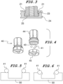
Figure 1 depicts one embodiment of adisplacer tool 10 according to the invention intended for use in a standard CNC machine which applies both pressing and rotational forces to thepunch fixture 12 such as seen infigure 2 . A complete description of a punch of this type is disclosed in pending co-ownedUS patent application 16/307, 133 tool tips 10 held within thepunch 12 as described below, fasteners can be affixed to malleable metal panels. In all of these embodiments the panels are prepared with blind receiving holes. - With continued reference to
Figure 1 , the main elements of the tool tip are abody 14 with attachment means 13 for being held within a rotarypunch press fixture 12 as seen inFigure 2 . In this, and other embodiments described herein, the working end of the tool has aflange 15 with an end face that has a plurality of displacers such as those shown at 16a,b,and c which surround acentral bore 17 that holds the fastener while it is being installed. During installation the tool is pressed to a given point and the tool is then rotated at that depth. Three separate displacers are shown, each with a different profile that acts upon the workpiece panel as the tool is rotated.Displacer 16a has a ramped profile that parts off the outside diameter of the metal which is pulled in and moves partially toward outside diameter of the fastener being installed. Its profile is vertically tapered along an arcuate ridge centered about the axial bore from a back end of the displacer of greatest height down to a front end of minimum height of the displacer where the ridge meets the end face.Displacer 16b, is like an additional snow plow that follows after the first displacer and has a configuration that moves the parted metal even closer to the outside periphery of the fastener being installed. And finally,displacer 16c, having a profile rectangular in section, then compresses the peak of displaced material to press the metal tightly down around the fastener. - As seen in
Figure 3 , these displacers illustrate how different displacers while operating independently function together to form the desired sequential composite displacement ofworkpiece material 21. The panel material is reshaped around and above the outside of aflange 23 offastener 25 which has been inserted into a blind hole of the receivingpanel 24. The workpiece panel is cut into and deformed without any loss of panel material. - In another embodiment seen in
figure 4 rollingballs 41 are employed in atool tip 40 to displace the panel material. - The balls roll between the
raceway 43 of thetip body 44 and a snap-in-place retainer 45 affixed to the end of the body. Theballs 41 rotate within the tool while simultaneously being pressed into the installation panel, pushing metal above a flange or ledge on the fastener as seen inFigure 3 . Torsional stresses in the panel are greatly reduced over fixed displacers, rolling friction exists, but is minimal.Figures 5 and 6 show before- and-after panel displacement how theballs 41 of the rolling ball type of displacer ofFigure 4 moves metal of a panel 51 to captivate a fastener. Rolling ball displacers eliminate sliding friction and the dragging of metal at the surface of the installation panel reducing installation stresses experienced with wedge profile rotary displacers. - In yet another
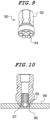
tool tip embodiment 70 depicted inFigure 7 , panel material is moved by a continuous displacement method by adisplacer ring 71 that wobbles. The displacer ring is loosely fitting to the tool body both radially and axially by attachment means 76 at the top to allow it to tip to one side or the other as the body is rotated. The displacer ring also has a raceway on which asingle ball bearing 73 can travel which further functions to retain theball 73 within the tool assembly. At its bottom end the displacer ring has a conical profile with acircular cutting edge 74. This displacer applies force to one portion of a full circle displacer through thesingle ball bearing 73 captivated to the tool body. As the displacer tip is rotated and pushed into the panel, the displacer ring wobbles. The displacement force is applied following the ball bearing around the circumference of the installation causing the displacer to wobble, and thus pressing only a portion of the displacer ring cutting edge atpoint 75 into the panel at any one point in time. There is no sliding or rolling contact between the displacer and the panel. Unlike multiple displacers which are all pressed into the panel together equally, only a small portion of this displacer is pressed in small increments as the tip is rotated. Since only a small portion of the displacer is being pressed at any given time throughout the installation period, the installation force is greatly reduced. There is no sliding or rolling friction between the panel and displacer, and as such torsional stresses are greatly reduced. -
Figure 8 depicts another embodiment which utilizes an incremental displacer similar to that shown inFigure 7 . This displacer substitutes the ball and raceway structures ofFigure 7 with acone gear 82 meshed with two circular cone racks 84 and 85, one above and one below. The incorporation of aspring 87 is also added to illustrate how stability to the displacer tip can be added when and if necessary. The cone gear guarantees no slipping between the gear faces and consequently ensures s full 360 degrees of pressing per rotation of the tool body. - In yet another
embodiment 90 seen infigures 9 and 10 , incremental displacement of panel material is achieved using an oscillation method with individual displacers. The term "oscillation" is used to describe the axial up and down stroking motion of the tool during the installation process, the downward motion referring to the as the advance of the tool toward the workpiece. The term "stroke" means a cyclical downward and then upward motion of the tool returning it to its starting position. - Referring now to
figure 9 , displacers 94 are machined and polished rounded surfaces or rounded fixed pins forming a unitary part of thetool body 92. The displacers shown are spherical at any point where they can contact thepanel 98 as seen inFigure 10 . Displacer geometry can also be wedge-shaped as in previous embodiments of this design. The tool body and displacers seen infigure 10 are unified in one solid machined body. - In this embodiment the tool is incrementally stroked, and rotated between strokes of a given length which results in a workpiece deformation to a predetermined depth level. As depicted the tool is rotated a set amount (e.g. 20°) before the next stroke is applied. Installation is achieved in incrementally advancing displacement depth levels. The number of axial strokes per depth level is determined by the amount of rotation in the tool following each stroke. Once the tool has rotated sufficiently to cover the angular distance between displacers, the stroke group is complete. The tool is then rotated a complete 360 degrees to smooth out the displaced material, and the process begins again at the next depth which are scalar increments of the initial depth.
- Table 1 below provides a breakdown of how installation is achieved via install groups. Each group corresponds to an install depth or 'level'. In this example the number of displacers is 6 (as in
figure 8 ), and hence the distance between them is 60 degrees (360 / N).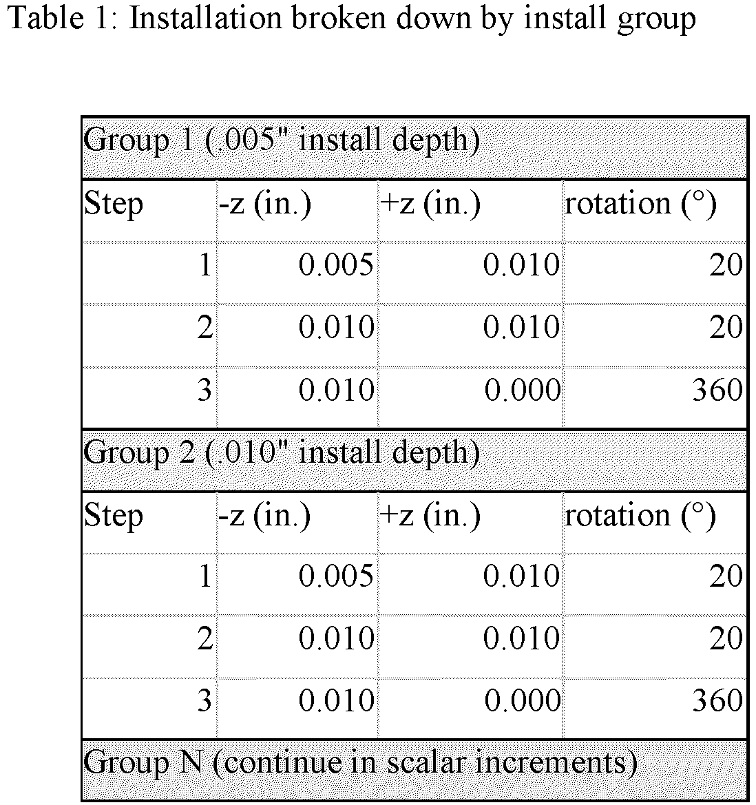
- Using this method install groups are customized for each part and correspond to blind hole depth, the number of displacers, and the angular distance between displacers. For instance, if there are 5 displacers the distance between them is 72 degrees. This distance is covered by any number of strokes depending on the amount of rotation per stroke. If the rotation per stroke is 12 degrees, then there are 5 strokes followed by a complete rotation of the tool occurring immediately after the final stroke. Individual displacers, whether ball or wedge are used specifically to minimize the projected area on panel while also moving enough material to achieve installation; this is the purpose of tool rotation following each stroke.
-
Figure 10 is a section view of the oscillating tip (fixed ball variant) after a part has been installed. The tip moves material over the part flange as in previous embodiments of this technology with the primary difference being kinetic interference friction is eliminated during the stroke process; rotation of the tool between strokes occurs free of contact with thepanel 98. Additionally, compressive panel stress at points ofdeformation 97 is relieved completely after each stroke of the tool which initiates panel contact with the displacer atpoint 95. The oscillating tip achieves installation of the part using a series of composite strokes and rotations applied in groups and at successive install depth levels. - Displacing panel material in depth increments achieved with axial oscillation reduces compressive stress build-up in the panel. Torsional stress buildup in the panel is nearly eliminated, and only occurs during the final step which provides a complete 360 degree 'smoothing' rotation. The result is reduced panel stress intended to prevent material near the
cosmetic face 96 from reaching a yielding point. - The embodiments described above disclose but a few of the possible examples of the invention which include a combination of mechanical elements with the same functional concepts, but not limited to those embodiments specifically disclosed. Many variations and modifications will be apparent to those of skill in the art without departing from the scope and spirit of the invention which shall be defined only by the following claims and their legal equivalents.
- The disclosure may include the following embodiments:
- Embodiment 1. A tool tip for a rotary press punch, comprising:
- a body having a shank, an axial bore, and a flange on the shank adjacent a bottom end of the body, said bore constructed and configured to hold a fastener;
- at least one workpiece displacer affixed along a periphery of the body surrounding the bore and adapted for displacing workpiece material around the outside of the fastener: and wherein the at least one displacer has a profile to maximize the non-destructive deformation of the workpiece to affix the fastener to the workpiece without the loss of panel material.
- Embodiment 2. The device of embodiment 1, wherein a distal end surface of the flange is orthogonal to the axial bore and having the at least one displacer that is vertically tapered along an arcuate ridge centered about said axial bore from a back end of the displacer of greatest height down to a front end of minimum height of the displacer where the ridge meets the end face.
- Embodiment 3. The device of embodiment 2, wherein an inside edge of said at least one displacer is chamfered from the ridge to the axial bore and wherein said displacer is chamfered from the displacer ridge. to an outer edge of the displacer and wherein the width of said displacer is tapered such that the front end of said displacer intersects said distal end surface at a point.
- Embodiment 4. The device of embodiment 1 further including a punch for a rotary press having a casing with a top end, a bottom end, and a central rotational axis; the top end being adapted for affixation to a rotary and vertically reciprocal spindle of an industrial machine; and wherein the tool tip is releasably held within the bottom end of the punch.
- Embodiment 5. The device of embodiment 1 wherein at least two of the displacer profiles are different.
- Embodiment 6. The device of embodiment 1 wherein the profiles are spherical.
- Embodiment 7. The device of embodiment 1 wherein all of the displacers are identical
- Embodiment 8. The device of embodiment 6 wherein the displacers are rotatable ball bearings.
- Embodiment 9. A tool tip for a rotary press punch, comprising:
- a body having a shank, an axial bore, and a radially extending flange on the shank adjacent a bottom end of the body;
- an axial bore within said body constructed and configured to hold a fastener;
- a displacer ring captivated to the body and loosely affixed to the shank axially and radially, said ring having a 360 angular degree cutting edge at the bottom thereof; and force transmission means located between the flange and the displacer ring constructed and configured to transmit a pressing force from the shank to the ring at a single point on the ring such that when the tool is pressed against a workpiece and rotated the ring performs a wobbling motion pressing only a portion of the cutting edge against the workpiece.
-
Embodiment 10. The device of embodiment 9 wherein the force transmission means is a single ball bearing. -
Embodiment 11. The device of embodiment 9 wherein the force transmission means is a pinion gear meshing with a top ring gear affixed to the flange and a bottom ring gear affixed to the displacer ring. -
Embodiment 12. The device of embodiment 9 further including a spring operative between a second flange at the bottom end of the body and an interior surface at the top of the displacer ring. -
Embodiment 13. A method of non-destructively displacing workpiece material around a fastener to affix the fastener to a workpiece, comprising the steps of:- providing a malleable metal workpiece panel with a blind hole;
- inserting a fastener having a flange adjacent its bottom end into the hole;
- providing a tool according to embodiment 1; and
- moving the tool axially and radially in a plurality of strokes against the workpiece to a predetermined first stroke level of workpiece deformation depth while rotating the tool after each stroke until a predetermined stroke or first group of strokes has been completed.
-
Embodiment 14. The method ofembodiment 13 wherein the steps are thereafter carried out at a second predetermined workpiece deformation level deeper than the first level during a second stroke or group of tool strokes. -
Embodiment 15. The method ofembodiment 13 wherein number of tool rotations per depth level is determined by the amount of rotation in the tool following each stroke. - Embodiment 16. The method of
embodiment 13 wherein said first group of strokes is completed when the tool has rotated a total of 360 angular degrees -
Embodiment 17. The method ofembodiment 14 wherein completed installation is achieved in incrementally advancing displacement depth levels. - Embodiment 18. The method of
embodiment 11 wherein the tool is rotated the same number of angular degrees between the strokes. - Embodiment 19. The method of
embodiment 13 wherein the displacers are spherical. - Embodiment 20. The method of
embodiment 14 further including a final smoothing step where the tool is rotated 360 angular degrees while held at a predetermined stroke level.
Claims (15)
- A tool tip for a rotary press punch, comprising:a body having a shank, an axial bore, and a flange on the shank adjacent a bottom end of the body, said bore constructed and configured to hold a fastener;at least one workpiece displacer affixed along a periphery of the body surrounding the bore and adapted for displacing workpiece material around the outside of the fastener: andwherein the at least one displacer has a profile to maximize the non-destructive deformation of the workpiece to affix the fastener to the workpiece without the loss of panel material.
- The device of claim 1, wherein a distal end surface of the flange is orthogonal to the axial bore and having the at least one displacer that is vertically tapered along an arcuate ridge centered about said axial bore from a back end of the displacer of greatest height down to a front end of minimum height of the displacer where the ridge meets the end face.
- The device of claim 2, wherein an inside edge of said at least one displacer is chamfered from the ridge to the axial bore and wherein said displacer is chamfered from the displacer ridge. to an outer edge of the displacer and wherein the width of said displacer is tapered such that the front end of said displacer intersects said distal end surface at a point.
- The device claim 1 further including a punch for a rotary press having a casing with a top end, a bottom end, and a central rotational axis; the top end being adapted for affixation to a rotary and vertically reciprocal spindle of an industrial machine; and wherein the tool tip is releasably held within the bottom end of the punch.
- The device of claim 1 wherein: at least two of the displacer profiles are different or, all of the displacers are identical.
- The device of claim 1 wherein the profiles are spherical.
- The device of claim 6 wherein the displacers are rotatable ball bearings.
- A method of non-destructively displacing workpiece material around a fastener to affix the fastener to a workpiece, comprising the steps of:providing a malleable metal workpiece panel with a blind hole;inserting a fastener having a flange adjacent its bottom end into the hole;providing a tool according to claim 1; andmoving the tool axially and radially in a plurality of strokes against the workpiece to a predetermined first stroke level of workpiece deformation depth while rotating the tool after each stroke until a predetermined stroke or first group of strokes has been completed.
- The method of claim 8 wherein the steps are thereafter carried out at a second predetermined workpiece deformation level deeper than the first level during a second stroke or group of tool strokes.
- The method of claim 8 wherein number of tool rotations per depth level is determined by the amount of rotation in the tool following each stroke.
- The method of claim 8 wherein said first group of strokes is completed when the tool has rotated a total of 360 angular degrees
- The method of claim 9 wherein completed installation is achieved in incrementally advancing displacement depth levels.
- The method of claim 8 wherein the tool is rotated the same number of angular degrees between the strokes.
- The method of claim 8 wherein the displacers are spherical.
- The method of claim 9 further including a final smoothing step where the tool is rotated 360 angular degrees while held at a predetermined stroke level.
Applications Claiming Priority (4)
| Application Number | Priority Date | Filing Date | Title |
|---|---|---|---|
| US202063014417P | 2020-04-23 | 2020-04-23 | |
| US202063033098P | 2020-06-01 | 2020-06-01 | |
| PCT/US2021/028287 WO2021216632A1 (en) | 2020-04-23 | 2021-04-21 | Rotary installation tools for clinch fasteners |
| EP21793372.0A EP4139068B1 (en) | 2020-04-23 | 2021-04-21 | Rotary installation tools for clinch fasteners |
Related Parent Applications (2)
| Application Number | Title | Priority Date | Filing Date |
|---|---|---|---|
| EP21793372.0A Division EP4139068B1 (en) | 2020-04-23 | 2021-04-21 | Rotary installation tools for clinch fasteners |
| EP21793372.0A Division-Into EP4139068B1 (en) | 2020-04-23 | 2021-04-21 | Rotary installation tools for clinch fasteners |
Publications (2)
| Publication Number | Publication Date |
|---|---|
| EP4563286A2 true EP4563286A2 (en) | 2025-06-04 |
| EP4563286A3 EP4563286A3 (en) | 2025-06-11 |
Family
ID=78221604
Family Applications (2)
| Application Number | Title | Priority Date | Filing Date |
|---|---|---|---|
| EP25170594.3A Pending EP4563286A3 (en) | 2020-04-23 | 2021-04-21 | Rotary installation tools for clinch fasteners |
| EP21793372.0A Active EP4139068B1 (en) | 2020-04-23 | 2021-04-21 | Rotary installation tools for clinch fasteners |
Family Applications After (1)
| Application Number | Title | Priority Date | Filing Date |
|---|---|---|---|
| EP21793372.0A Active EP4139068B1 (en) | 2020-04-23 | 2021-04-21 | Rotary installation tools for clinch fasteners |
Country Status (8)
| Country | Link |
|---|---|
| US (2) | US12115631B2 (en) |
| EP (2) | EP4563286A3 (en) |
| JP (1) | JP2023522677A (en) |
| CN (1) | CN115803129A (en) |
| CA (1) | CA3180805A1 (en) |
| MX (1) | MX2022013190A (en) |
| TW (1) | TWI879945B (en) |
| WO (1) | WO2021216632A1 (en) |
Families Citing this family (1)
| Publication number | Priority date | Publication date | Assignee | Title |
|---|---|---|---|---|
| CN117564955B (en) * | 2023-09-15 | 2025-09-30 | 南京航空航天大学 | Pressure-driven lightweight fastening tool structure and its preparation method based on 4D printing technology |
Citations (2)
| Publication number | Priority date | Publication date | Assignee | Title |
|---|---|---|---|---|
| US133A (en) | 1837-03-03 | benjamin bull | ||
| US16307A (en) | 1856-12-23 | Improvement in automatic rakes for harvesters |
Family Cites Families (22)
| Publication number | Priority date | Publication date | Assignee | Title |
|---|---|---|---|---|
| US1842571A (en) * | 1929-12-26 | 1932-01-26 | Arthur H Parker | Method of applying bail ears to containers |
| US4018257A (en) * | 1975-12-15 | 1977-04-19 | Cold Fasteners, Inc. | Self-flanging nut and joint construction |
| DE2607334A1 (en) | 1976-02-23 | 1977-08-25 | Goetz Metallbau Gmbh | Fixing of anchoring bolts to metal facade plates - has tapered head of anchoring bolt inserted in blind hole whose edge is then deformed |
| US4402124A (en) * | 1982-01-25 | 1983-09-06 | Guenther Krueger | Method of pressure locking an aperatured nut into a die-side hole of a metal plate |
| DE3507489A1 (en) | 1985-03-02 | 1986-04-30 | Daimler-Benz Ag, 7000 Stuttgart | Method for the one-sided unreleasable fastening of a bolt to a metal/wood laminate and a wobble-type riveting device carrying it out |
| JPS6415630U (en) * | 1987-07-21 | 1989-01-26 | ||
| US5338139A (en) * | 1993-10-20 | 1994-08-16 | Penn Engineering & Manufacturing Corp. | Shrouded captive screw |
| US5655396A (en) | 1995-09-25 | 1997-08-12 | General Motors Corporation | Roll peening device |
| US6077003A (en) * | 1998-06-16 | 2000-06-20 | Hydra-Lock Corporation | Tool holder |
| US6527489B2 (en) * | 2000-12-07 | 2003-03-04 | International Business Machines Corporation | Concealed low distorting self crimping stud and insertion method |
| US6908690B2 (en) * | 2002-04-29 | 2005-06-21 | The Boeing Company | Method and apparatus for friction stir welding |
| US20040042871A1 (en) * | 2002-09-04 | 2004-03-04 | Wojciechowski Stanley E. | Self-attaching female fastener element, sealed fastener and panel assembly and method of forming same |
| JP4002171B2 (en) * | 2002-11-26 | 2007-10-31 | カルソニックカンセイ株式会社 | Pipe connection structure, pipe connection method and caulking mold |
| DE102004020676A1 (en) * | 2004-04-28 | 2005-11-24 | Profil-Verbindungstechnik Gmbh & Co. Kg | Method and device for attaching a fastener to a component, in particular to a sheet metal part |
| US7480971B2 (en) * | 2005-04-28 | 2009-01-27 | Profile Verbindungstechnik Gmbh & Co., Kg | Method and device for mounting a fastener element on a part, particularly a sheet metal part |
| CN103894814A (en) * | 2012-12-27 | 2014-07-02 | 鸿富锦精密工业(深圳)有限公司 | Riveting device |
| DE102014117401A1 (en) * | 2014-11-27 | 2016-06-02 | Tkr Spezialwerkzeuge Gmbh | riveting tool |
| DE102015109255A1 (en) * | 2015-06-11 | 2016-12-15 | Profil Verbindungstechnik Gmbh & Co. Kg | Method for fastening a rivet element and corresponding fastening system |
| DE102015109244A1 (en) * | 2015-06-11 | 2016-12-15 | Profil Verbindungstechnik Gmbh & Co. Kg | Method for fastening a rivet element and corresponding fastening system therefor |
| US20180058486A1 (en) * | 2016-08-29 | 2018-03-01 | Penn Engineering & Manufacturing Corp. | Fastener for Thin-Sheet Materials |
| CA3254958A1 (en) | 2017-05-09 | 2025-04-07 | Penn Engineering & Manufacturing Corp. | Fastener and installation method for very thin sheets |
| CN113302406B (en) * | 2019-01-08 | 2023-04-04 | 阿久曼特知识产权有限公司 | Tight-fitting fastener |
-
2021
- 2021-04-21 CN CN202180043893.6A patent/CN115803129A/en not_active Withdrawn
- 2021-04-21 EP EP25170594.3A patent/EP4563286A3/en active Pending
- 2021-04-21 EP EP21793372.0A patent/EP4139068B1/en active Active
- 2021-04-21 US US17/236,033 patent/US12115631B2/en active Active
- 2021-04-21 MX MX2022013190A patent/MX2022013190A/en unknown
- 2021-04-21 CA CA3180805A patent/CA3180805A1/en active Pending
- 2021-04-21 WO PCT/US2021/028287 patent/WO2021216632A1/en not_active Ceased
- 2021-04-21 JP JP2022563174A patent/JP2023522677A/en not_active Ceased
- 2021-04-23 TW TW110114621A patent/TWI879945B/en active
-
2024
- 2024-07-23 US US18/780,723 patent/US20240375254A1/en active Pending
Patent Citations (2)
| Publication number | Priority date | Publication date | Assignee | Title |
|---|---|---|---|---|
| US133A (en) | 1837-03-03 | benjamin bull | ||
| US16307A (en) | 1856-12-23 | Improvement in automatic rakes for harvesters |
Also Published As
| Publication number | Publication date |
|---|---|
| JP2023522677A (en) | 2023-05-31 |
| TW202202245A (en) | 2022-01-16 |
| US12115631B2 (en) | 2024-10-15 |
| MX2022013190A (en) | 2023-01-05 |
| EP4139068A1 (en) | 2023-03-01 |
| EP4563286A3 (en) | 2025-06-11 |
| TWI879945B (en) | 2025-04-11 |
| WO2021216632A1 (en) | 2021-10-28 |
| US20210331227A1 (en) | 2021-10-28 |
| US20240375254A1 (en) | 2024-11-14 |
| CA3180805A1 (en) | 2021-10-28 |
| EP4139068A4 (en) | 2024-03-27 |
| CN115803129A (en) | 2023-03-14 |
| EP4139068B1 (en) | 2025-05-28 |
Similar Documents
| Publication | Publication Date | Title |
|---|---|---|
| US11969840B2 (en) | Method of fastening a fastener | |
| KR102890167B1 (en) | Pipe Receiving Assembly for a Pipe Grooving Device | |
| EP2722115B1 (en) | Face spline molding device and face spline molding method | |
| US20240375254A1 (en) | Rotary installation tools for clinch fasteners | |
| EP1915225B1 (en) | Method for producing internal and external toothings on thin-walled, cylindrical hollow parts | |
| EP1621269B1 (en) | Method of manufacturing part with internal gear and rolling machine | |
| US3962899A (en) | Method and apparatus for making an eccentric locking collar | |
| US6470724B1 (en) | Tool for producing a gear part having external toothing | |
| GB2389066A (en) | Cold working of two metal components in a die tool | |
| US12502740B2 (en) | Fastener installation tool |
Legal Events
| Date | Code | Title | Description |
|---|---|---|---|
| REG | Reference to a national code |
Ref country code: DE Ref legal event code: R079 Free format text: PREVIOUS MAIN CLASS: B25B0027000000 Ipc: B21J0015120000 |
|
| PUAI | Public reference made under article 153(3) epc to a published international application that has entered the european phase |
Free format text: ORIGINAL CODE: 0009012 |
|
| PUAL | Search report despatched |
Free format text: ORIGINAL CODE: 0009013 |
|
| STAA | Information on the status of an ep patent application or granted ep patent |
Free format text: STATUS: THE APPLICATION HAS BEEN PUBLISHED |
|
| AC | Divisional application: reference to earlier application |
Ref document number: 4139068 Country of ref document: EP Kind code of ref document: P |
|
| AK | Designated contracting states |
Kind code of ref document: A2 Designated state(s): AL AT BE BG CH CY CZ DE DK EE ES FI FR GB GR HR HU IE IS IT LI LT LU LV MC MK MT NL NO PL PT RO RS SE SI SK SM TR |
|
| AK | Designated contracting states |
Kind code of ref document: A3 Designated state(s): AL AT BE BG CH CY CZ DE DK EE ES FI FR GB GR HR HU IE IS IT LI LT LU LV MC MK MT NL NO PL PT RO RS SE SI SK SM TR |
|
| RIC1 | Information provided on ipc code assigned before grant |
Ipc: B25B 27/00 20060101ALI20250508BHEP Ipc: F16B 37/06 20060101ALI20250508BHEP Ipc: B21K 25/00 20060101ALI20250508BHEP Ipc: B23P 11/00 20060101ALI20250508BHEP Ipc: B23P 19/06 20060101ALI20250508BHEP Ipc: B21J 15/12 20060101AFI20250508BHEP |