EP4563232A1 - Dekantierzentrifuge zur trennung von einsatzmaterial - Google Patents
Dekantierzentrifuge zur trennung von einsatzmaterial Download PDFInfo
- Publication number
- EP4563232A1 EP4563232A1 EP23213452.8A EP23213452A EP4563232A1 EP 4563232 A1 EP4563232 A1 EP 4563232A1 EP 23213452 A EP23213452 A EP 23213452A EP 4563232 A1 EP4563232 A1 EP 4563232A1
- Authority
- EP
- European Patent Office
- Prior art keywords
- flight
- conveyor screw
- central body
- bearing surface
- defining
- Prior art date
- Legal status (The legal status is an assumption and is not a legal conclusion. Google has not performed a legal analysis and makes no representation as to the accuracy of the status listed.)
- Pending
Links
Images


Classifications
-
- B—PERFORMING OPERATIONS; TRANSPORTING
- B04—CENTRIFUGAL APPARATUS OR MACHINES FOR CARRYING-OUT PHYSICAL OR CHEMICAL PROCESSES
- B04B—CENTRIFUGES
- B04B1/00—Centrifuges with rotary bowls provided with solid jackets for separating predominantly liquid mixtures with or without solid particles
- B04B1/20—Centrifuges with rotary bowls provided with solid jackets for separating predominantly liquid mixtures with or without solid particles discharging solid particles from the bowl by a conveying screw coaxial with the bowl axis and rotating relatively to the bowl
- B04B2001/2041—Centrifuges with rotary bowls provided with solid jackets for separating predominantly liquid mixtures with or without solid particles discharging solid particles from the bowl by a conveying screw coaxial with the bowl axis and rotating relatively to the bowl with baffles, plates, vanes or discs attached to the conveying screw
-
- B—PERFORMING OPERATIONS; TRANSPORTING
- B04—CENTRIFUGAL APPARATUS OR MACHINES FOR CARRYING-OUT PHYSICAL OR CHEMICAL PROCESSES
- B04B—CENTRIFUGES
- B04B1/00—Centrifuges with rotary bowls provided with solid jackets for separating predominantly liquid mixtures with or without solid particles
- B04B1/20—Centrifuges with rotary bowls provided with solid jackets for separating predominantly liquid mixtures with or without solid particles discharging solid particles from the bowl by a conveying screw coaxial with the bowl axis and rotating relatively to the bowl
- B04B2001/205—Centrifuges with rotary bowls provided with solid jackets for separating predominantly liquid mixtures with or without solid particles discharging solid particles from the bowl by a conveying screw coaxial with the bowl axis and rotating relatively to the bowl with special construction of screw thread, e.g. segments, height
-
- B—PERFORMING OPERATIONS; TRANSPORTING
- B04—CENTRIFUGAL APPARATUS OR MACHINES FOR CARRYING-OUT PHYSICAL OR CHEMICAL PROCESSES
- B04B—CENTRIFUGES
- B04B1/00—Centrifuges with rotary bowls provided with solid jackets for separating predominantly liquid mixtures with or without solid particles
- B04B1/20—Centrifuges with rotary bowls provided with solid jackets for separating predominantly liquid mixtures with or without solid particles discharging solid particles from the bowl by a conveying screw coaxial with the bowl axis and rotating relatively to the bowl
- B04B2001/2083—Configuration of liquid outlets
Definitions
- the present invention relates to a conveyor screw for a decanter centrifuge, a decanter centrifuge and a method of operating a decanter centrifuge.
- Centrifugal based methods are often preferred when extracting oil from oil containing plant- or animal items.
- the oil is separated from the residual solids and liquids, preferably by using a decanter centrifuge.
- oil extraction such as vegetable oil extraction
- the solids are removed in a first separation stage and the oil is removed in a second separation stage after the solids have been removed.
- some oil or fat will inevitably be trapped in the compacted solids cake. This oil is considered to be lost as it is not easily recoverable even by resuspension of the solids.
- WO 2010/142299 A1 relates to a decanter centrifuge having a conveyor hub with a tubular steel body with an inner core made of a material such as carbon fibre reinforced epoxy.
- WO 2020/109135 A1 relates to a method of producing a low-fat product from a starting material made of a fat and/or oil containing plant- or animal item.
- the method comprises extracting a greater part of the extractable oil and/or fat originally contained in the plant- or animal item using a first decanter and leaving a residue of solids and liquids.
- US 7156801 relates to a decanter centrifuge comprising a conveyor screw with one or more flights and having a nominal transport speed varying along the longitudinal axis.
- the nominal transport speed depends in a non-linear way on the screw pitch.
- the screw used having two radially offset helices extending over the cylindrical region of the drum and the worm with the same or different winding directions and/or different pitches, so that a radially outer first screw thread and a radially inner second screw thread are formed, so that a part of the suspension to be processed when the drum and screw rotates through the second radially - in relation to the axis of rotation - further inward helix or in conveyed in the radially inner screw flight in a different direction and/or in the same direction and/or at a different speed than at the same time another part of the suspension that is located in the area of the radially further outer helix or the radially outer screw flight.
- US 20150209804 describes an apparatus comprising an outer drum, an inner drum, an activation spiral and a heavy-material discharging spiral.
- EP 0868217 discloses a decanter centrifuge having several blades arranged to convey axially in the outer drum sludge having settled on the inside of this drum.
- EP 2130607 B1 relates to a decanter centrifuge having the inlet arranged at an end of the casing opposite the end in which the opening for expelling the solid phase is arranged.
- DE 2651657 relates to a centrifugal decanter having a clear fluid discharge between the inlet and the solids outlet.
- US 3268159 relates to a centrifugal decanter in which the feed zone is closer to large end hub than both conveyor bearings.
- JP 62106856 relates to a centrifugal decanter in which the solids and liquids discharge are on the same side.
- US 3494472 relates to a centrifugal separator in the form of a sieve drum.
- US 7022061 describes a centrifugal separator with power recovery discharge pipes for the light phase.
- US 9089852 describes a centrifugal decanter mentioning that the solid discharge port may be oriented at an angle to the radial to achieve an energy-saving repulse effect
- WO 2012/062337 A2 relates to a centrifugal separator comprising an outlet housing being rotatable around an adjustment axis.
- EP 0506835 B1 relates to a decanter centrifuge having at least one bearing of the conveyor supported at the free end of a trunnion.
- EP 0602766 B1 relates to a decanter centrifuge having a central hub having radially projecting support ribs.
- EP 2440335 A1 relates to a decanter centrifuge having conveyor screw comprising a hub with a cylindrical part and a generally conical part, the two parts being interconnected by broad mutually spaced ribs extending in the longitudinal direction.
- EP 2926911 B1 relates to a decanter centrifuge having a centrifuge worm which is mounted at one of its axial end areas by means of a connecting flange.
- EP 3177403 B1 relates to a decanter centrifuge having individual openings in the cylindrical section of the screw hub.
- WO 2021122878A1 relates to a decanter centrifuge having, at least in the inlet area, a screw hub with an open wall structure.
- WO 2021122884A1 relates to a decanter centrifuge having a transverse disk for stabilizing the worm hub construction.
- WO 2022096734A1 relates to a centrifuge screw having rods between at least two winding sections.
- the rods are formed completely or almost completely spaced.
- WO 2022096739A1 relates to a screw hub for a centrifuge screw having in the longitudinal direction having at least sections of an open wall structure.
- WO 2022096745A1 relates to a centrifuge screw having an open wall structure.
- the open wall structure extending at most over a length of 50% of the total length of the cylindrical longitudinal section.
- US 8841469 relates to a method of recovering oil from corn by adding a chemical additive.
- the object of the present invention is according to a first aspect achieved by a conveyor screw for a decanter centrifuge, the conveyor screw comprising a central body extending in a longitudinal direction, the central body comprising a first bearing surface at a first end of the central body and a second bearing surface at a second end of the central body, the second end being opposite the first end, the central body further defining a cylindrical portion adjacent the first bearing surface and a conical portion adjacent the second bearing surface, the conveyor screw further comprising a screw thread being attached to the central body, the screw thread extending in the longitudinal direction and defining an outer perimeter extending circumferentially about the cylindrical portion, the central body being free from any fluid openings between the first bearing surface and the second bearing surface.
- the conveyor screw is used in a bowl of a decanter centrifuge to convey a slurry being a mixture of the solids and the water towards the heavy phase outlet. It rotates at a differential speed relative to the bowl for the thread to impose a conveying action on the slurry.
- the heavy phase outlet is located at a conical portion of the bowl.
- the bearing surfaces of the conveyor screw are located at opposite ends of the central body. There is typically a drive and a gearbox at one of the bearings for rotating the conveyor screw. During operation, the drive applies a torque onto the central body causing the conveyor screw to rotate.
- the typical conveyor screws used in standard decanter centrifuges accommodates a feed passage along the axis of the central body and at least one fluid opening along the axial direction for introducing the flowable feed material to be separated into the decanter centrifuge.
- this imposes structural limitations to the conveyor screw and decreases the rigidity of the conveyor screw as the fluid opening constitutes a void which limits the stiffness of the conveyor screw.
- the fluid opening is typically located near the middle of the central body along the axial direction which further decreases the bending rigidity of the overall structure.
- the feed passage inside the conveyor screw limits the use of reinforcing structures inside the conveyor screw for increasing the bending rigidity.
- the stiffness of the conveyor screw also depends on the diameter of the central body.
- An increased diameter of the central body will increase the stiffness of the conveyor screw. Consequently, the length of the central body can be increased if the diameter of the central body increases.
- an increased diameter of the central body will reduce the available process volume between the conveyor hub and the bowl wall and the retention time of the process media will be reduced and the oil extraction will be compromised.
- the presence of openings in the central body lowers the stiffness of the conveyor screw which lowers the natural frequency, also known as the eigenfrequency, of the conveyor screw. Further, making the central body longer will lower the natural frequency of the conveyor screw. Operating a long conveyor screw at high rotational speeds near the natural frequency of the conveyor screw may cause harmful vibrations that may cause the conveyor screw to fail. This also limits the length of the conveyor screw when operating at high speeds.
- the central body being free from any openings between the first bearing surface and a second bearing surface.
- any opening will constitute a constitutes a void which limits the stiffness of the conveyor screw.
- the conveyor screw comprises a cage structure extending from the central body at the first bearing surface in a direction away from the second bearing surface, the screw thread being at least partially attached to the cage structure.
- the cage structure part comprises an inner ring attached to the central body, and outer ring and a plurality of ribs interconnecting the inner ring and the outer ring.
- the screw thread can be attached onto the ribs while the inner and outer ring keeps the structural stability of the cage structure.
- the central body defines a cylinder at the cylindrical portion and a truncated cone at the conical portion.
- the cylinder and the truncated cone extend along the longitudinal direction.
- the screw thread follows the outline of the central body.
- the outer perimeter of the screw thread defines a diameter and the screw thread defines a length in the longitudinal direction, the ratio between the diameter and the length exceeding 3.9, preferably exceeding 4.2, more preferably exceeding 4.5, most preferably exceeding 4.9.
- a ratio between the diameter and the length of the central part can be established.
- the ratio is established between the outer perimeter of the screw thread instead of the diameter of the central body.
- Typical limits for maintaining sufficient stiffness for decanter centrifuges having a fluid opening in the central body is about 4. However, a higher ratio exceeding 4.2 is possible provided no fluid opening is provided in the central body. Such as a ratio exceeding 4.5 or 4.9.
- the diameter is exceeding 640mm, preferably exceeding 670mm, more preferably exceeding 700mm, most preferably exceeding 715mm.
- the central body defines a hollow interior which is at least partially reinforced by a reinforcing material extending at least half the distance between the first bearing surface and the second bearing surface, the reinforcing material preferably being fibre reinforced epoxy.
- a hollow and fibre reinforced central body will allow the conveyor screw to be lighter and longer while maintaining the stiffness and structural stability of the conveyor screw.
- the screw thread comprising:
- a flight is understood to be a plate welded radially to the central body of the conveyor screw to provide the conveying surface of the conveyor screw.
- the conveyor screw further defining a third flight extending parallel with the second flight, the second flight extending to the second outer perimeter whereas the third flight extending to a third outer perimeter, the second flight and the third flight defining an oil channel between themselves, the oil channel defining a width between the second flight and the third flight being less than the distance between the central body and the second outer perimeter.
- the second flight and the third flight are formed as two parallel flights as described above.
- the second flight will spread out the solids and the third flight will collect the oil.
- the oil will flow towards the light phase outlet in the channel between the second flight and the third flights.
- the third outer perimeter defining a third diameter, the third diameter being smaller than the second diameter.
- the second flight passes through gaps in the first flight.
- first flight and the second flight can be intertwined with minimal interruption of the first flight. This will allow the conveying of the solids to be more efficient.
- the conveyor screw comprises a fourth flight being substantially identical to the second flight and extending in parallel with the second flight, and a fifth flight corresponding to the third flight and running parallel with the fourth flight establishing a further oil channel together with the fourth flight, the fourth flight and the fifth flight being phase shifted relative to the second flight and the third flight, respectively, preferably by 180°
- a fifth flight corresponding to the third flight and running parallel with the fourth flight establishing a further oil channel.
- the object of the present invention is according to a second aspect achieved by decanter centrifuge comprising a rotatable bowl and a conveyor screw according to any of the preceding embodiments accommodated inside the rotatable bowl, the rotatable bowl defining an inner surface substantially matching the outer perimeter of the screw thread.
- the conveyor screw according to the first aspect is preferably mounted in a bowl of a decanter centrifuge.
- the object of the present invention is according to a first aspect achieved by method of operating a decanter centrifuge according to the second aspect, wherein the method comprising: continuously introducing a flowable material to be separated into the bowl at a rate higher than 75m3/h while rotating the bowl to apply a g-force of at least 3000 G at the bowl wall.
- the decanter centrifuge according to the second aspect is preferably operated at a high g-force and flow rate to allow an efficient oil release from the feed.
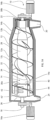
- Fig. 1A is a side view of a decanter centrifuge 10 according to the present invention.
- the decanter centrifuge 10 comprises a rotatable bowl 12 and a conveyor screw 14.
- the bowl 12 has a cylindrical part 12a and a conical part 12b.
- the conveyor screw 14 has a corresponding cylindrical part 14a and conical part 14b.
- the bowl 12 is rotated by a drive motor 16a and the conveyor screw 14 is rotated by a back drive motor 16b.
- the back drive motor 16b is typically connected via a gearbox (not shown).
- An inlet 18 is provided for introducing the feed into the decanter centrifuge 10.
- the bowl 12 comprises a heavy phase outlet 20 at a small end hub 22 at the conical part 12b of the of the bowl 12 and a light phase outlet 24 at a base 26 forming a large end hub at the cylindrical part 12a of the bowl 12.
- the conveyor screw 14 comprises a central body 28 extending in a longitudinal direction between a first bearing surface 30a at the cylindrical part 14a and a second bearing surface 30b at the conical part 14b.
- the conveyor screw 14 comprises a first flight 32 being attached to the central body 28.
- the first flight 32 extends over both the cylindrical part 14a and the conical part 14b of the conveyor screw 14.
- the first flight 32 extending to an inner wall 12c of the bowl 12 and defines a pitch angle being less than 20°.
- the present embodiment further comprises a second flight 34 not extending to the inner wall 12c of the bowl 12 and defining a pitch angle being greater than 30°.
- the second flight 34 does not extend to the inner wall 12c and extends over only the cylindrical part 14a of the conveyor screw 14.
- the base 26 comprising a trunnion 40 which encompasses feed inlets 42 42' for the feed and the bearing surface 30a for the conveyor screw 14.
- the feed inlets 42 42' communicating with the inlet 18.
- the trunnion 40 also comprises at outlet housings 44 extending into the bowl 12 for transporting the light phase from the bowl 12 to the light phase outlet 24.
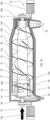
- Fig. 1B is a side view of a decanter centrifuge 10 according to the present invention showing the inlet and outlet flows.
- the feed is introduced via the inlet 18 as shown by the arrow.
- the feed can be a crushed oil-containing plant- or animal item such as crushed corn seeds.
- the feed enters the bowl 12 via feed inlets 42 42'.
- the feed is separated into a slurry fraction and an oil fraction by centrifugal forces from the rotation of the bowl 12.
- the slurry fraction is a mixture of solids and water.
- the slurry fraction form a heavy phase and are conveyed by the conveyor screw 14 and is discharged at the heavy phase outlet 20 as shown by the arrow.
- the oil fraction forms a light phase which is discharged via the outlet housings 44 and light phase outlet 24 as shown by the arrow.
- the slurry fraction being heavier than the oil fraction and will thus flow outwards and accumulate at the inner wall 12c of the bowl 12, the oil fraction being lighter than the slurry fraction and will thus flow inwards and accumulates near the central body 28.
- the first flight 32 collects the slurry fraction and conveys it towards the heavy phase outlet 20 of the bowl 12, whereas the second flight 34 being able to scrape and spread out the slurry fraction.
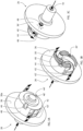
- FIG. 2A is a perspective view of a circular base 26 according to the present invention.
- the base 26 comprises an inner surface 36 facing the interior of the bowl (not shown here) and an outer surface (not visible here) being opposite the inner surface 36 and facing the outside of the bowl.
- the base 26 comprising the trunnion 40 which constitutes a cylindrical element positioned about a centre point C of the base 26 protruding in a longitudinal direction L from the inner surface 36 of the base 26 into the bowl.
- the trunnion 40 comprising a bearing surface 30a for the conveyor screw and feed inlets 42 42' for introducing feed (not shown) into the bowl.
- the bearing surface 30a being located further away in the longitudinal direction L from the inner surface 36 than the feed inlets 42 42' and encircles the centre point C.
- the bearing surface 30a being spaced apart from the centre point C in a radial direction r.
- the radial direction r being perpendicular to the longitudinal direction L.
- the feed inlets 42 42' is located more spaced apart in radial direction r from the centre point C than the bearing surface 40.
- two feed inlets 42 and 42' are provided, whereby the feed inlet 42 is the main feed inlet and the feed inlet 42' is an overflow inlet used during temporary high inflows.
- the trunnion 40 further comprising the outlet housing 44.
- the outlet housing 44 being at least partially cylindrical and extending from the base 26 through the trunnion 40 in the longitudinal direction L into the bowl.
- the outlet housing 44 is located spaced apart in radial direction r from the centre point C, typically further spaced apart from the centre point C than the bearing surface 30a.
- the screw flight 34 ends at the outlet housing 44.
- two outlet housings 44 and 44' are provided spaced apart by 180 degrees about the centre point C.
- the light phase being oil/fat.
- the light phase flows inwardly due to centrifugal forces and enters one of the outlet housings 44 44' as shown by the arrows.
- the light phase enters the outlet housing 44 44' via a light phase opening 46.
- the light phase opening 46 defines a weir edge extending in parallel with the first adjustment axis of the outlet housing 44 44' and defining in normal use a level of the light phase within the bowl.
- the outlet housing 44 44' has a cylindroconical shape having the light phase opening 46' in a conically shaped part of the outlet housing 44 for a smoother flow.
- FIG. 2B is a perspective view of the base showing the discharge of the light phase.
- the light phase enters the outlet housings 44 44' at a radial distance from the centre point C.
- the radial distance of the opening 46 (and thereby the weir) from the centre point C can be adjusted by rotating the outlet housing 44 44' about an adjustment axis A. In this way the level of the light phase within the bowl can be adjusted.
- the bowl rotates causing the feed (not shown) inside the bowl to separate in a heavy phase (not shown) and light liquid phase having a surface at a level, which is slightly above the level of the weir edge thereby providing a pressure head driving the light phase out of the bowl through the opening 46 and the outlet housing 44.
- FIG. 2C is a perspective view of the base from the rear side showing the outer surface 36' and the discharge of the light phase as shown by the arrows.
- the outlet housing 44 extends to the outer surface 36' of the base 26 and defines an outlet 48 at the outer surface 36' of the base 26 for ejecting the light phase.
- the outlet housing 44 can be adjusted about the adjustment axis A from the outside.
- FIG. 3A is a perspective view of the base showing the inflow of the flowable material.
- the flowable material is introduced centrally in the longitudinal direction and flows out in the radial direction into the bowl (not shown) via the feed inlets 42 42'.
- FIG. 3B is a perspective cutaway view of the base 26 showing the interior of the trunnion 40.
- the flowable material is deflected by deflectors 50 from flowing in the longitudinal direction to a direction substantially corresponding to the tangential direction of the rotation of the bowl (not shown). In this way, less time within the bowl is needed to accelerate the flowable material to the bowl rotation speed, and the separation can therefore be more efficient.
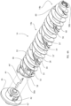
- Fig. 4A is a perspective view of the conveyor screw 14 according to the present invention.
- the conveyor screw 14 comprises the first flight 32 and the second flight 34 being attached to the central body 28.
- the first flight 32 extends over both the cylindrical part 14a and the conical part 14b of the conveyor screw 14 and defines a pitch angle being less than 20° for being able to collect the slurry fraction and convey it towards the heavy phase outlet of the bowl.
- the second flight 34 extends in the longitudinal direction along the cylindrical portion of the conveyor screw 14 only. The first flight 32 and the second flight 34 being at least partially intertwined.
- Both the first flight 32 and the second flight 34 has the same winding direction, however, the second flight 34 defining a pitch angle being more than 30° for scraping and spreading out the slurry at the inner surface of the bowl.
- the second flight 34 extends to a smaller outer perimeter than the first flight 32 for the slurry to be spread out on the inner surface of the bowl. This will allow more oil to be released from the slurry.
- the conveyor screw 14 is further provided with a baffle plate 60 between the cylindrical part 14a and the conical part 14b for preventing oil from flowing towards the heavy phase outlet of the bowl.
- the conveyor screw 14 is further provided with a third flight 52 extending to a smaller outer perimeter than the second flight 34. The purpose of the third flight 52 is to define an oil channel 54 between the second flight 34 and the third flight 52 to allow the oil to flow towards the light phase outlet of the bowl.
- the first flight 32 comprises gaps 56 for allowing the second flight 34 and the third flight 52 to pass through.
- the first flight 32 is slightly offset at the gaps 56 to scrape any slurry which would otherwise be missed due to the gaps 56.
- the conveyor screw 14 further comprises a cage structure 58 extending from the first bearing surface 30a away from the second bearing surface 30b for carrying the first screw 32 beyond the first bearing surface 32a.
- the present conveyor screw 14 also includes an additional fourth flight 34' and fifth flight 52' which essentially correspond to the second flight 34 and third flight 52, respectively, albeit being 180° phase shifted. In this way there will be an additional oil channel 54' and two spread-out effects on the slurry for each turn of the conveyor screw 14.
- the present view also shows the base 26 being attached to the first bearing surface 30a during use.
- the base 28 comprises the feed inlet 42 42' and the outlet housing 44.
- Fig. 4B is a perspective view of the conveyor screw 14 according to the present invention when the base 26 is connected to the first bearing surface 30a.
- the central body 28 being free from any fluid openings between the first bearing surface 30a and the second bearing surface 30b for increasing the structural stability and stiffness of the conveyor screw 14.
Landscapes
- Centrifugal Separators (AREA)
Priority Applications (2)
| Application Number | Priority Date | Filing Date | Title |
|---|---|---|---|
| EP23213452.8A EP4563232A1 (de) | 2023-11-30 | 2023-11-30 | Dekantierzentrifuge zur trennung von einsatzmaterial |
| PCT/EP2024/084012 WO2025114493A1 (en) | 2023-11-30 | 2024-11-28 | A decanter centrifuge for separating feed material |
Applications Claiming Priority (1)
| Application Number | Priority Date | Filing Date | Title |
|---|---|---|---|
| EP23213452.8A EP4563232A1 (de) | 2023-11-30 | 2023-11-30 | Dekantierzentrifuge zur trennung von einsatzmaterial |
Publications (1)
| Publication Number | Publication Date |
|---|---|
| EP4563232A1 true EP4563232A1 (de) | 2025-06-04 |
Family
ID=89029961
Family Applications (1)
| Application Number | Title | Priority Date | Filing Date |
|---|---|---|---|
| EP23213452.8A Pending EP4563232A1 (de) | 2023-11-30 | 2023-11-30 | Dekantierzentrifuge zur trennung von einsatzmaterial |
Country Status (1)
| Country | Link |
|---|---|
| EP (1) | EP4563232A1 (de) |
Citations (28)
| Publication number | Priority date | Publication date | Assignee | Title |
|---|---|---|---|---|
| US3268159A (en) | 1962-10-16 | 1966-08-23 | Voith Gmbh J M | Centrifuge |
| US3494472A (en) | 1967-06-16 | 1970-02-10 | Heinkel Maschinenbau Kg Ernst | Sieve centrifuge |
| DE2651657A1 (de) | 1976-11-12 | 1978-05-24 | Robert Kern | Schneckenzentrifuge mit suspensionsfuehrung nach dem gleichstromprinzip |
| JPS62106856A (ja) | 1985-11-05 | 1987-05-18 | Kubota Ltd | 横型遠心濃縮機 |
| EP0506835B1 (de) | 1989-12-29 | 1994-07-13 | Alfa-Laval Separation A/S | Dekantierzentrifuge |
| EP0868217A1 (de) | 1995-12-21 | 1998-10-07 | Alfa Laval Separation Ab | Dekantierzentrifuge |
| EP0602766B1 (de) | 1992-12-17 | 2000-06-07 | Alfa Laval Separation Inc. | Dekantierzentrifuge zur hochgradigen Eindickung |
| ITRM20000663A1 (it) * | 2000-12-13 | 2002-06-13 | Rapanelli Fioravante Spa | Coclea che non produce rimescolamento di liquidi, utilizzabile in unacentrifuga orizzontale per l'estrazione di olio da un impasto oleoso. |
| US7022061B2 (en) | 2002-10-15 | 2006-04-04 | Andritz Ag | Centrifuge discharge port with power recovery |
| US7156801B2 (en) | 2002-04-22 | 2007-01-02 | Alfa Laval Copenhagen A/S | Decanter centrifuge with a screw conveyor having a varying pitch |
| WO2010142299A1 (en) | 2009-06-12 | 2010-12-16 | Alfa Laval Corporate Ab | A decanter centrifuge and a screw conveyor |
| EP2130607B1 (de) | 2008-06-06 | 2012-04-11 | Mantovani & Vicentini S.r.L. | Zentrifugalabscheider |
| EP2440335A1 (de) | 2009-06-12 | 2012-04-18 | Alfa Laval Corporate AB | Zentrifugalabscheider |
| WO2012062337A2 (en) | 2010-11-12 | 2012-05-18 | Alfa Laval Corporate Ab | A centrifugal separator and an outlet element for a centrifugal separator |
| US8841469B2 (en) | 2011-03-21 | 2014-09-23 | Solenis Technologies, L.P. | Chemical additives and use thereof in stillage processing operations |
| US9089852B2 (en) | 2011-12-22 | 2015-07-28 | Gea Mechanical Equipment Gmbh | Fully jacketed screw centrifuge with a hose segment arranged in the solids capture chamber |
| US20150209804A1 (en) | 2012-08-15 | 2015-07-30 | Qinzhou Aurasource Technology Inc. | Centrifugal separation device |
| EP2926911B1 (de) | 2014-04-04 | 2016-07-06 | Flottweg SE | Vollmantelschneckenzentrifuge mit einem anbindeflansch |
| EP3177403B1 (de) | 2014-08-05 | 2018-05-02 | Flottweg SE | Schnecke einer vollmantelschneckenzentrifuge |
| KR102025270B1 (ko) * | 2019-05-20 | 2019-09-25 | 주식회사 회림테크 | 스크류 프레스 탈수장치 |
| WO2020109135A1 (en) | 2018-11-30 | 2020-06-04 | Alfa Laval Corporate Ab | Method of producing a low-fat product and a system for producing a low-fat product |
| DE102019102623A1 (de) | 2019-02-04 | 2020-08-06 | Gea Mechanical Equipment Gmbh | Verfahren zum Klären einer Suspension von Feststoffen |
| WO2021122878A1 (de) | 2019-12-19 | 2021-06-24 | Flottweg Se | Einlaufbereich einer zentrifugenschnecke und vollmantelschneckenzentrifuge |
| WO2021122884A1 (de) | 2019-12-19 | 2021-06-24 | Flottweg Se | Querscheibe einer zentrifugenschnecke und vollmantelschneckenzentrifuge |
| WO2022096745A1 (de) | 2020-11-09 | 2022-05-12 | Flottweg Se | Zentrifugenschnecke und vollmantelschneckenzentrifuge |
| WO2022096739A1 (de) | 2020-11-09 | 2022-05-12 | Flottweg Se | Schneckennabe, zentrifugenschnecke und vollmantelschneckenzentrifuge |
| WO2022096734A1 (de) | 2020-11-09 | 2022-05-12 | Flottweg Se | Zentrifugenschnecke und vollmantelschneckenzentrifuge |
| DE102020129478A1 (de) | 2020-11-09 | 2022-06-02 | Flottweg Se | Schneckennabe, Zentrifugenschnecke und Vollmantelschneckenzentrifuge |
-
2023
- 2023-11-30 EP EP23213452.8A patent/EP4563232A1/de active Pending
Patent Citations (28)
| Publication number | Priority date | Publication date | Assignee | Title |
|---|---|---|---|---|
| US3268159A (en) | 1962-10-16 | 1966-08-23 | Voith Gmbh J M | Centrifuge |
| US3494472A (en) | 1967-06-16 | 1970-02-10 | Heinkel Maschinenbau Kg Ernst | Sieve centrifuge |
| DE2651657A1 (de) | 1976-11-12 | 1978-05-24 | Robert Kern | Schneckenzentrifuge mit suspensionsfuehrung nach dem gleichstromprinzip |
| JPS62106856A (ja) | 1985-11-05 | 1987-05-18 | Kubota Ltd | 横型遠心濃縮機 |
| EP0506835B1 (de) | 1989-12-29 | 1994-07-13 | Alfa-Laval Separation A/S | Dekantierzentrifuge |
| EP0602766B1 (de) | 1992-12-17 | 2000-06-07 | Alfa Laval Separation Inc. | Dekantierzentrifuge zur hochgradigen Eindickung |
| EP0868217A1 (de) | 1995-12-21 | 1998-10-07 | Alfa Laval Separation Ab | Dekantierzentrifuge |
| ITRM20000663A1 (it) * | 2000-12-13 | 2002-06-13 | Rapanelli Fioravante Spa | Coclea che non produce rimescolamento di liquidi, utilizzabile in unacentrifuga orizzontale per l'estrazione di olio da un impasto oleoso. |
| US7156801B2 (en) | 2002-04-22 | 2007-01-02 | Alfa Laval Copenhagen A/S | Decanter centrifuge with a screw conveyor having a varying pitch |
| US7022061B2 (en) | 2002-10-15 | 2006-04-04 | Andritz Ag | Centrifuge discharge port with power recovery |
| EP2130607B1 (de) | 2008-06-06 | 2012-04-11 | Mantovani & Vicentini S.r.L. | Zentrifugalabscheider |
| WO2010142299A1 (en) | 2009-06-12 | 2010-12-16 | Alfa Laval Corporate Ab | A decanter centrifuge and a screw conveyor |
| EP2440335A1 (de) | 2009-06-12 | 2012-04-18 | Alfa Laval Corporate AB | Zentrifugalabscheider |
| WO2012062337A2 (en) | 2010-11-12 | 2012-05-18 | Alfa Laval Corporate Ab | A centrifugal separator and an outlet element for a centrifugal separator |
| US8841469B2 (en) | 2011-03-21 | 2014-09-23 | Solenis Technologies, L.P. | Chemical additives and use thereof in stillage processing operations |
| US9089852B2 (en) | 2011-12-22 | 2015-07-28 | Gea Mechanical Equipment Gmbh | Fully jacketed screw centrifuge with a hose segment arranged in the solids capture chamber |
| US20150209804A1 (en) | 2012-08-15 | 2015-07-30 | Qinzhou Aurasource Technology Inc. | Centrifugal separation device |
| EP2926911B1 (de) | 2014-04-04 | 2016-07-06 | Flottweg SE | Vollmantelschneckenzentrifuge mit einem anbindeflansch |
| EP3177403B1 (de) | 2014-08-05 | 2018-05-02 | Flottweg SE | Schnecke einer vollmantelschneckenzentrifuge |
| WO2020109135A1 (en) | 2018-11-30 | 2020-06-04 | Alfa Laval Corporate Ab | Method of producing a low-fat product and a system for producing a low-fat product |
| DE102019102623A1 (de) | 2019-02-04 | 2020-08-06 | Gea Mechanical Equipment Gmbh | Verfahren zum Klären einer Suspension von Feststoffen |
| KR102025270B1 (ko) * | 2019-05-20 | 2019-09-25 | 주식회사 회림테크 | 스크류 프레스 탈수장치 |
| WO2021122878A1 (de) | 2019-12-19 | 2021-06-24 | Flottweg Se | Einlaufbereich einer zentrifugenschnecke und vollmantelschneckenzentrifuge |
| WO2021122884A1 (de) | 2019-12-19 | 2021-06-24 | Flottweg Se | Querscheibe einer zentrifugenschnecke und vollmantelschneckenzentrifuge |
| WO2022096745A1 (de) | 2020-11-09 | 2022-05-12 | Flottweg Se | Zentrifugenschnecke und vollmantelschneckenzentrifuge |
| WO2022096739A1 (de) | 2020-11-09 | 2022-05-12 | Flottweg Se | Schneckennabe, zentrifugenschnecke und vollmantelschneckenzentrifuge |
| WO2022096734A1 (de) | 2020-11-09 | 2022-05-12 | Flottweg Se | Zentrifugenschnecke und vollmantelschneckenzentrifuge |
| DE102020129478A1 (de) | 2020-11-09 | 2022-06-02 | Flottweg Se | Schneckennabe, Zentrifugenschnecke und Vollmantelschneckenzentrifuge |
Similar Documents
| Publication | Publication Date | Title |
|---|---|---|
| EP0664727B1 (de) | Verschleissfester korb für eine mit schnecke versehene zentrifuge | |
| RU2223151C2 (ru) | Центрифуга с дополнительной секцией ротора | |
| EP1372863B1 (de) | Vollmantel-schneckenzentrifuge mit automatischer feststoffentleerung | |
| US7001324B2 (en) | Method of retrofitting a decanting centrifuge | |
| CN1305578C (zh) | 螺旋式离心机 | |
| JPH0242951B2 (de) | ||
| EP0897752B1 (de) | Zentrifuge mit heftig bewegtem Feststoffkuchen | |
| CN116583354A (zh) | 螺杆毂、离心式螺杆以及无孔转筒式螺杆离心机 | |
| US6030332A (en) | Centrifuge system with stacked discs attached to the housing | |
| AU2006257485B2 (en) | Three-phase solid bowl screw centrifuge and method of controlling the separating process | |
| AU2006331435B2 (en) | Screw-type solid bowl centrifuge | |
| CN103443577B (zh) | 使多相固体在重相排放流中高效地流动的离心液体分离机 | |
| JPH06269697A (ja) | デカンター型遠心分離機 | |
| CN104394996A (zh) | 层流离心分离机 | |
| EP2475461B1 (de) | Zentrifugaltrenner und trennverfahren dafür | |
| RU2482922C2 (ru) | Центрифуга с сетчатой корзиной | |
| EP4563232A1 (de) | Dekantierzentrifuge zur trennung von einsatzmaterial | |
| EP4563233A1 (de) | Dekantierzentrifuge zur trennung von einsatzmaterial | |
| EP4563234A1 (de) | Dekantierzentrifuge zur trennung von einsatzmaterial | |
| EP4563231A1 (de) | Dekantierzentrifuge zur trennung von einsatzmaterial | |
| WO2025114493A1 (en) | A decanter centrifuge for separating feed material | |
| EP0258012A2 (de) | Flüssig-Fest-Zentrifugalseparator | |
| GB2083381A (en) | Uniflow decanter centrifuge | |
| WO2003101619A1 (en) | Centrifugal separator bowl assembly with flow guide | |
| JP3748798B2 (ja) | 遠心分離機 |
Legal Events
| Date | Code | Title | Description |
|---|---|---|---|
| PUAI | Public reference made under article 153(3) epc to a published international application that has entered the european phase |
Free format text: ORIGINAL CODE: 0009012 |
|
| STAA | Information on the status of an ep patent application or granted ep patent |
Free format text: STATUS: THE APPLICATION HAS BEEN PUBLISHED |
|
| AK | Designated contracting states |
Kind code of ref document: A1 Designated state(s): AL AT BE BG CH CY CZ DE DK EE ES FI FR GB GR HR HU IE IS IT LI LT LU LV MC ME MK MT NL NO PL PT RO RS SE SI SK SM TR |