EP4560950A2 - Zweiphasen-ratenanpassung für wlan - Google Patents
Zweiphasen-ratenanpassung für wlan Download PDFInfo
- Publication number
- EP4560950A2 EP4560950A2 EP24213489.8A EP24213489A EP4560950A2 EP 4560950 A2 EP4560950 A2 EP 4560950A2 EP 24213489 A EP24213489 A EP 24213489A EP 4560950 A2 EP4560950 A2 EP 4560950A2
- Authority
- EP
- European Patent Office
- Prior art keywords
- data packets
- rate adaptation
- data
- sending
- transmission
- Prior art date
- Legal status (The legal status is an assumption and is not a legal conclusion. Google has not performed a legal analysis and makes no representation as to the accuracy of the status listed.)
- Pending
Links
Images




Classifications
-
- H—ELECTRICITY
- H04—ELECTRIC COMMUNICATION TECHNIQUE
- H04L—TRANSMISSION OF DIGITAL INFORMATION, e.g. TELEGRAPHIC COMMUNICATION
- H04L1/00—Arrangements for detecting or preventing errors in the information received
- H04L1/0001—Systems modifying transmission characteristics according to link quality, e.g. power backoff
- H04L1/0002—Systems modifying transmission characteristics according to link quality, e.g. power backoff by adapting the transmission rate
- H04L1/0003—Systems modifying transmission characteristics according to link quality, e.g. power backoff by adapting the transmission rate by switching between different modulation schemes
-
- H—ELECTRICITY
- H04—ELECTRIC COMMUNICATION TECHNIQUE
- H04W—WIRELESS COMMUNICATION NETWORKS
- H04W28/00—Network traffic management; Network resource management
- H04W28/16—Central resource management; Negotiation of resources or communication parameters, e.g. negotiating bandwidth or QoS [Quality of Service]
- H04W28/18—Negotiating wireless communication parameters
- H04W28/22—Negotiating communication rate
-
- H—ELECTRICITY
- H04—ELECTRIC COMMUNICATION TECHNIQUE
- H04L—TRANSMISSION OF DIGITAL INFORMATION, e.g. TELEGRAPHIC COMMUNICATION
- H04L1/00—Arrangements for detecting or preventing errors in the information received
- H04L1/0001—Systems modifying transmission characteristics according to link quality, e.g. power backoff
- H04L1/0009—Systems modifying transmission characteristics according to link quality, e.g. power backoff by adapting the channel coding
-
- H—ELECTRICITY
- H04—ELECTRIC COMMUNICATION TECHNIQUE
- H04L—TRANSMISSION OF DIGITAL INFORMATION, e.g. TELEGRAPHIC COMMUNICATION
- H04L1/00—Arrangements for detecting or preventing errors in the information received
- H04L1/0001—Systems modifying transmission characteristics according to link quality, e.g. power backoff
- H04L1/0015—Systems modifying transmission characteristics according to link quality, e.g. power backoff characterised by the adaptation strategy
- H04L1/0017—Systems modifying transmission characteristics according to link quality, e.g. power backoff characterised by the adaptation strategy where the mode-switching is based on Quality of Service requirement
-
- H—ELECTRICITY
- H04—ELECTRIC COMMUNICATION TECHNIQUE
- H04L—TRANSMISSION OF DIGITAL INFORMATION, e.g. TELEGRAPHIC COMMUNICATION
- H04L1/00—Arrangements for detecting or preventing errors in the information received
- H04L1/0001—Systems modifying transmission characteristics according to link quality, e.g. power backoff
- H04L1/0015—Systems modifying transmission characteristics according to link quality, e.g. power backoff characterised by the adaptation strategy
- H04L1/0017—Systems modifying transmission characteristics according to link quality, e.g. power backoff characterised by the adaptation strategy where the mode-switching is based on Quality of Service requirement
- H04L1/0018—Systems modifying transmission characteristics according to link quality, e.g. power backoff characterised by the adaptation strategy where the mode-switching is based on Quality of Service requirement based on latency requirement
-
- H—ELECTRICITY
- H04—ELECTRIC COMMUNICATION TECHNIQUE
- H04L—TRANSMISSION OF DIGITAL INFORMATION, e.g. TELEGRAPHIC COMMUNICATION
- H04L1/00—Arrangements for detecting or preventing errors in the information received
- H04L1/0001—Systems modifying transmission characteristics according to link quality, e.g. power backoff
- H04L1/0023—Systems modifying transmission characteristics according to link quality, e.g. power backoff characterised by the signalling
- H04L1/0026—Transmission of channel quality indication
-
- H—ELECTRICITY
- H04—ELECTRIC COMMUNICATION TECHNIQUE
- H04L—TRANSMISSION OF DIGITAL INFORMATION, e.g. TELEGRAPHIC COMMUNICATION
- H04L47/00—Traffic control in data switching networks
- H04L47/10—Flow control; Congestion control
- H04L47/25—Flow control; Congestion control with rate being modified by the source upon detecting a change of network conditions
-
- H—ELECTRICITY
- H04—ELECTRIC COMMUNICATION TECHNIQUE
- H04W—WIRELESS COMMUNICATION NETWORKS
- H04W24/00—Supervisory, monitoring or testing arrangements
- H04W24/08—Testing, supervising or monitoring using real traffic
-
- H—ELECTRICITY
- H04—ELECTRIC COMMUNICATION TECHNIQUE
- H04W—WIRELESS COMMUNICATION NETWORKS
- H04W28/00—Network traffic management; Network resource management
- H04W28/02—Traffic management, e.g. flow control or congestion control
- H04W28/06—Optimizing the usage of the radio link, e.g. header compression, information sizing, discarding information
- H04W28/065—Optimizing the usage of the radio link, e.g. header compression, information sizing, discarding information using assembly or disassembly of packets
Definitions
- the present invention relates to wireless communications, and more particularly, to rate adaptation in wireless communications.
- QoS Quality of Service
- an IEEE 802.11 based wireless system an unlicensed spectrum is used for wireless communications. Contention in the shared wireless spectrum may result in excessive latency. To meet QoS requirements of a certain class of time-sensitive applications, it is important to manage the delivery latency of predictable data packets.
- a method of configuring rate adaptation for data transmission comprising: for a first phase: sending a set of test data packets; and determining a first rate adaptation configuration based on feedback corresponding to the sending of the set of test data packets; for a second phase: sending a set of application data packets according to the first rate adaptation configuration; and determining a second rate adaptation configuration based on at least one of the sending of the set of test data packets or the set of application data packets.
- the two-phase rate adaptation method provides for rate adaptation configurations based on a set of test data packets sent during a pre-data transmission phase and on application data packets subsequently sent during a data transmission phase, where the rate adaptation configuration for the data transmission is based on the test data packets, the application data packets, or a combination of the test and application data packets.
- rate adaptation is a mechanism in IEEE 802.11 based wireless systems that selects a transmission rate according to the current channel quality (e.g., based on the wireless channel conditions).
- Existing wireless-capable devices that use rate adaptation mechanisms for IEEE 802.11 based wireless systems transmit the application data packets and use rate adaptation modules that adjust the rate and other transmission parameters (e.g., modulation and coding scheme (MCS) (e.g., BPSK 1 ⁇ 2, QPSK 3 ⁇ 4, etc.), guard interval (e.g., OFDM guard interval setting), spatial stream (e.g., multiple-in, multiple out (MIMO) configurations), channel bandwidth, etc.) based on channel conditions as determined from the response, or absence thereof, to the transmission (e.g., the response from a receiving device, such as an acknowledgement (ACK)).
- MCS modulation and coding scheme
- guard interval e.g., OFDM guard interval setting
- spatial stream e.g., multiple-in, multiple out (MIMO) configurations
- channel bandwidth
- MCS tables are publicly available, such as found on websites SemFio networks (e.g., https://semfionetworks.com/blog/wi-fi-7-mcs-table/), or at https://mcsindex.net/, to name a few.
- SemFio networks e.g., https://semfionetworks.com/blog/wi-fi-7-mcs-table/
- https://mcsindex.net/ to name a few.
- Minstrel Minstrel, though others exist. In effect, existing systems and methods configure the rate adaptation based on feedback from the data transmissions, adjusting the rate over several rounds of trial and error.
- a two-phase rate adaptation method may achieve the desired rate adaptation configuration before application data packets are actually delivered and/or speed-up the rate adaptation convergence time to improve reliability and/or timeliness in wireless transmissions.
- a reduction in the rate adaption convergence time and/or the waiting time for wireless channel access may be achieved.
- a two-phase rate adaptation method is described or illustrated herein using a periodic transmission pattern.
- the data transmission patterns contemplated herein may generally be of the form of an expected data transmission patterns, whether periodic, predictable, and/or of a known or historical pattern.
- a wireless communication system environment that is embodied, in one example, as an office-based WLAN environment with one or more APs serving multiple wireless-capable devices (e.g., notebooks, tablets, phones, etc.)
- some examples are described below that have application to various smart environments (e.g., smart factory, hospital, or research facilities that may use specialized wireless-capable devices, such as robots).
- a general summary of challenges in 802.11 based wireless communications is described.
- link (or similarly, rate) adaptation mechanisms are applied.
- a set of transmission configuration schemes e.g., including modulation and coding schemes
- a wireless communication device may select a suitable transmission configuration with the rate adaptation mechanism.
- ACK-based rate adaptation mechanisms e.g., Minstrel
- ACK-based rate adaptation mechanisms rely on the previous success/failure data reception and the corresponding ACK messages, a suitable transmission scheme may be selected after several rounds of data transmission, which may lead to a long convergence time.
- the long convergence time of rate adaptation may result in reduced channel utilization and/or high transmission errors.
- FIG. 1 shows an embodiment of an example two-phase rate adaptation method 10.
- the two-phase rate adaptation method 10 may be implemented on WLAN devices (e.g., WLAN access point, WLAN station, WLAN router and/or hotspot device) in a wireless (802.11-based) communication system, such as that shown in FIG. 9 and explained below.
- the rate adaptation may be conducted in two phases, shown in FIG. 1 as phase1 rate adaptation 12 (RA (PHS1)) and phase2 rate adaptation 14 (RA (PHS2)).
- Phase1 is also referred to herein also as a pre-data transmission phase
- phase2 is also referred to herein as a data transmission phase.
- a set of test data packets are sent 16 to enable the sending device, based on feedback, to perform rate adaptation (e.g., for testing a better rate adaptation configuration (e.g., MCS setting, MIMO configuration, etc.)) for the subsequent, upcoming data transmission in phase 2.
- the set of test data packets may be data packets with an empty data payload, or with a small, dummy data payload (e.g., unimportant or meaningless data packet payload), where the sending of the test data packets 16 is intended to elicit a transmission result 18 (e.g., TX RSLT, which may include receipt or no receipt of an ACK) that may be used for determining a rate adaptation configuration.
- TX RSLT which may include receipt or no receipt of an ACK
- Reference herein to a set of test data packets (or set of application data packets) may include a single packet or plural packets.
- phase1 rate adaptation 12 Subsequent to the phase1 rate adaptation 12 (and the feedback associated with the transmission result 18) is the start of the data transmission phase 20, and in particular, the commencement/start of the phase2 rate adaptation 14.
- application data packets e.g., with a meaningful packet data payload
- a transmission result 24 e.g., TX RSLT, which may include the presence or absence of an ACK
- the application data packets include reliable (e.g., ultra-reliable) and/or low-latency application data.
- the application data packets may include control messages that are used to control another device.
- the data transmission 22 (comprising one or more application data packets) in phase2 may be based on rate adaptation configured according to test data packets sent in phase1, application data packets sent in phase2, or a combination of test and application data packets from phase1 and phase2.
- the transmission of the application data packets completes a round of data transmission 26, which may result in a record 28 (of rate adaptation configuration from the last transmission round) for use in a next round of data transmissions according to phase1 and phase2 rate adaptation configurations.
- rate adaptation is only performed during the data transmission phase.
- a WLAN device configured with rate adaptation logic (e.g., module) may send (transmit) plural packets (e.g., five (5) packets), and receive a transmission result (e.g., ACK, or no response, depending on the channel conditions) for those corresponding sent packets. Based on the transmission result, the WLAN device may adjust the MCS, rate, etc.
- rate adaptation logic e.g., module
- the WLAN device may adjust the MCS, rate, etc.
- certain embodiments of the two-phase rate adaptation method use two phases, phase1 and phase 2, for configuring the rate adaptation.
- phase1 rate adaptation 12 is added to existing rate adaptation methodology, where test data packets (e.g., with empty or dummy payloads) are sent 16, preliminarily to the application data packet transmissions 22 of phase2, in what may also be referred to as a trial phase.
- test data packets 16 enable the sending WLAN device, based on the transmission result 18, to adapt to a more suitable scheme before the data transmission phase (phase2).
- the phase1 rate adaptation 12 and phase 2 rate adaptation 14 are implemented in the same WLAN device, such as via rate adaptation module/logic (e.g., software and/or hardware).
- test data packets may be considered unimportant packets (e.g., are not used to control a device, such as a robot, a notebook/tablet or a cell phone), but rather, may be artificially generated, with empty or dummy (meaningless) payload data.
- rate adaptation functionality in the sending WLAN device Based on the transmission result 18 (e.g., based on receiving or not receiving an ACK from a receiving device), rate adaptation functionality in the sending WLAN device adjusts to a suitable rate adaptation configuration (e.g., a suitable MCS scheme for channel conditions, different rate, etc.), and then the data transmission phase 20 commences, where application data packets (e.g., in some instances, important, device-controlling packets) are sent 22 (and where based on the transmission result 24, rate adaptation may, possibly, again be adjusted). At the end of the data transmission phase 26 (completed round), the two-phase rate adaptation method 10 repeats itself.
- a suitable rate adaptation configuration e.g., a suitable MCS scheme for channel conditions, different rate, etc.
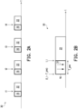
- FIG. 2A shows an example expected (e.g. periodic) transmission pattern 30 using the two-phase rate adaptation method 10.
- the expected transmission pattern 30 is illustrated using four (4) rounds of data transmissions. For instance (and with continued reference to FIG. 1 ), beginning from the left in FIG. 2A , shown is a bolded block corresponding to transmission of a set of test data packets 16 based on the phase1 rate adaptation 12, and adjacent to that bolded block is another (un-bolded) block representing transmission of a set of application data packets 22 based on the phase2 rate adaptation 14.
- the first two blocks labeled 16 and 22 represent a first round of data transmissions (e.g., including the set of application data packets and the set of test data packets), and the following set of like-labeled, bolded/un-bolded blocks to the right of the first set of blocks along the time axis represent subsequent rounds of data transmissions with a total
- annotations signifying the expected arrival time (e.g., of the application data packets) from another device.
- the application environment is an office having a plurality of distributed APs/routers controlled by a controller (e.g., main computer or server) and a plurality of wireless-capable devices (e.g., notebooks), where the plurality of distributed APs/routers may communicate with the plurality of notebooks by transmitting commands having application data packets via a wired/wireless WLAN.
- a controller e.g., main computer or server
- wireless-capable devices e.g., notebooks
- the plurality of distributed APs/routers may communicate with the plurality of notebooks by transmitting commands having application data packets via a wired/wireless WLAN.
- all the devices in the wired/wireless WLAN may include the control algorithms, and hence there is no expected delivery of commands that are relayed to the wireless-capable devices (e.g., notebooks) at or about the delivery time.
- the intent is to communicate to the, for instance, notebooks periodically (e.g., update a notebook every 100 milliseconds (msec)) via a respective round among four (4) rounds of data transmissions, with the first round beginning at or around t1, the second round beginning at or around t2, the third round beginning at or around t3, and the fourth round beginning at or around t4.
- the notebooks may receive the application data packets (e.g., commands) at or around t1, take an action, and then there is a delay while the notebook reacts, and then the next command (t2) is received (and transmitted), and so on to achieve a given control method.
- application data packets e.g., commands
- each transmission round involves two rate adaptation phases (phase 1 and phase2).
- the respective set of test data packets are sent according to a pre-data transmission phase at a time immediately preceding the corresponding expected arrival time (e.g., t1, t2, t3, and t4) to enable preliminary adjustments to rate adaptation before starting the respective application data packet transmissions.
- a pre-data transmission phase at a time immediately preceding the corresponding expected arrival time (e.g., t1, t2, t3, and t4) to enable preliminary adjustments to rate adaptation before starting the respective application data packet transmissions.
- FIG. 2B shows an enlarged view of one of the (sent) set of test data packets 16 plus set of application data packets 22 and some important parameters.
- the pre-data transmission phase (phase1) comprising the transmission of the set of test data packets, may be of a duration equal to T_pre.
- each pre-data transmission phase may begin before the arrival time at (t_i - T_pre).
- the pre-data transmission phase begins on time, a simple example is helpful to illustrate the mechanism. If the application data transmissions 22 (phase2) are to commence at 10 msec, and the pre-data transmission is configured to run for a duration of 1 msec, then the pre-data transmission phase (phase1) should run from 9 msec to 10 msec.
- FIG. 2B also illustrates some additional configuration parameters.
- the downward arrows 31 within the block corresponding to the pre-data transmission phase represent the number of pre-data or test data packets (e.g., a quantity of two in this example, though other quantities may be used, including 3, 5, etc.).
- the configuration may also include one or more parameters that may be used for configuring a suitable (e.g., improved or optimal) MCS during the pre-data transmission phase (phase1), and includes one or any combination of T_pre, (t_i - T_pre), number of test data packets, time gap between the test data packets, and size (e.g., bytes) of each test data packet or size in the aggregate.
- FIGS. 2A-2B are based on the pre-data transmission phase beginning on time (as expected, such as T_pre time before the arrival time, t), there are instances where the pre-data transmission time may be deferred (or prematurely terminated as described below). For instance, the pre-data transmission time may be deferred due to a busy channel (e.g., where there is an unfinished transmission by a nearby, channel-contending wireless device).
- FIG. 3 shows an enlarged view, and certain parameters, of one of the test plus application data packet transmissions from the expected transmission pattern shown in FIG. 2A , where the pre-data packet transmission is delayed because of a busy channel.
- wireless transmissions e.g., transmissions complying with IEEE 802.11
- FIG. 2A illustrates expected starting times for commencing the pre-data transmission phase
- FIG. 3 shows this latter situation as a channel busy time 32.
- the channel busy time 32 might extend over (encroach upon) the previously described ( FIG. 2B ) pre-data transmission phase commencement time of (t_i - T_pre) and beyond, such as from a neighboring WLAN device with an unfinished transmission.
- the commencement time of (t_i - T_pre) should be deferred until the channel is no longer busy (e.g., a neighboring WLAN device stops transmission).
- the pre-data transmission starting time is deferred by a certain amount of time 34 due to the channel busy time 32. Since it is important that the application data packets are delivered 22 as expected (e.g., at t_i, so that, for instance, the notebook (or robots, etc.) receive their commands on time), then the duration of the pre-data transmission goes from T_pre ( FIG.
- the pre-data transmission 16 shown in FIG. 2B is shortened to pre-data transmission 16a by the deferred amount of time 34, causing the start of the pre-data transmission phase to be delayed to (t_i - T_pre(adjusted)). Accordingly, the pre-data transmission period has a delayed start, but ends on time because the next data transmission (phase 2) should start as expected (t_i) to ensure reliability and timeliness in the delivery of application data packets (e.g., ensure the notebooks (or robots) receive their commands on time). Even though the channel busy time 32 causes a shorter pre-data transmission duration, the pre-data transmission is still used to find a better rate adaptation (e.g., MCS) for the data transmission.
- MCS rate adaptation
- the expected starting time for the pre-data transmission phase is configured, and when the channel is busy and encroaches upon the pre-data transmission phase starting time, the pre-data transmission starting time is deferred in an attempt to preserve the expected starting time for sending the application data packets.
- the WLAN device may receive the application data packets before the expected transmission is predicted to occur, enabling sooner-than-expected access to the channel.
- pre-emption may be used, where the pre-data transmission phase may be shortened (e.g., prematurely terminated) in favor of an early delivery of the application data packets.
- the data transmission phase (phase2) pre-empts the pre-data transmission phase (phase1).
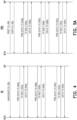
- FIGS. 4-8 show various example signaling flows for uplink (UL) and downlink (DL) implementations using the two-phase rate adaptation method, based on a different situs of control.
- Each of the signaling flow diagrams show, at the top of the diagram, at least a station (STA) and an access point (AP) as transmitting and receiving devices of a wireless communication system.
- the AP may be a WLAN AP (e.g., an IEEE 802.11 AP), or a WiFi router, or a notebook or phone serving as a hot spot, among other devices.
- the station may be an IEEE 802.11 device, or more generally, a WLAN device, with an 802.11 WLAN radio interface, which may include a laptop, a notebook, a tablet, a mobile phone, or an IEEE 802.11 STA, among other devices.
- the WLAN devices and/or WLAN AP may include rate adaptation logic (e.g., a hardware and/or software module), where rate adaptation may be conducted with two phases, as explained above. For instance, rate adaptation may be conducted in a pre-data transmission phase (phase1), where the pre-data packet transmission may be applied for testing a better rate adaptation configuration (e.g., MCS setting and/or MIMO configuration setting) for an upcoming data transmission. Additionally, rate adaptation may then be conducted in a data-transmission phase (phase 2).
- rate adaptation logic e.g., a hardware and/or software module
- the AP may be an IEEE 802.11 access point (e.g., which in ordinary usage, may be a hot spot at home (e.g., a WiFi router at home) or a notebook functionally being a hotspot). More specific to one of the use cases described herein, the two-phase rate adaptation method may be implemented in more critical applications with higher reliability and/or latency standards, such as in an office environment or smart environment.
- the station may be an 802.11 device (e.g., 802.11 WLAN device).
- the operation is initiated by the AP (i.e., AP-controlled).
- the application data packets are transmitted from the AP to the STA.
- the AP may optionally announce a high-quality DL service 38 (announce DL), followed by, in this non-limiting example, three (3) sets (or rounds) of data transmissions (each round distinguished by the reference numeral suffices, a, b, and c for the first, second, and third rounds).
- the AP has knowledge of the data traffic pattern and/or has the capability of configuring the data traffic pattern.
- the data transmission is expected to arrive at the AP in a set of pre-determined time points (which may include some minor delay variations), which may be embodied as periodic data traffic with a fixed time period between two data packets.
- the data traffic is expected to be transmitted from the AP to the STA.
- the AP may obtain information regarding the expected data traffic pattern, including being based on an application type in a packet header, based on an address of a source node and/or the address of the destination node, based on a QoS type indicated in the packet header, from a configuration message that is sent by an application server, and/or from a configuration message that is sent by a WLAN controller.
- the AP transmits the pre-data transmission packets 40a (PRE-DATA TX).
- PRE-DATA TX the pre-data transmission packets 40a
- the starting time may be configured as (t_i - T_pre), where T_pre is a configurable parameter for the protocol operation.
- the AP may start channel access contention at (t_i - T_pre), where the AP essentially attempts to gain the right to use the channel. If the channel contention is successful, the AP may become a TXOP (transmission opportunity) holder. Within the TXOP duration, the AP has the right to transmit.
- the AP may transmit a set of (one or more) pre-data-transmission packets, where each of the pre- data-transmission packets may be configured as a data packet with a small dummy data payload, a data packet with an empty data payload, a null packet (e.g., Null data PPDU), or a control packet that requests a channel state measurement (e.g., a sounding PPDU).
- a null packet e.g., Null data PPDU
- a control packet that requests a channel state measurement (e.g., a sounding PPDU).
- the AP may transmit multiple pre-data-transmission packets until the number of transmitted pre-data-transmission packets is equal to an upper limit packet number, N_max, the time used for pre-data-transmission is greater than or equal to a time threshold, T_max, or the application data (which is predicted to arrive at time t_i) has arrived at the AP.
- the AP may (prematurely) terminate the pre-data-transmission phase and start the data transmission (e.g., pre-emption, as explained above).
- the station responds (or does not respond) with a transmission result 42a (TX RSLT).
- the transmission result 42a may be an ACK and/or channel feedback.
- transmission result though typically explained below in the context of actually receiving an ACK, generally refers to using the presence or absence of an ACK as feedback to enable a determination of a rate adaptation configuration.
- some channel measurement e.g., an indication of channel quality
- feedback is provided, which the STA can send to the AP.
- the STA upon receiving the pre-data transmission 40a, may respond with an ACK message, conduct channel measurements and report the channel state information to the AP, or respond with an ACK with piggybacked channel state information feedback (or as explained above, there may be instances, particularly in a low-quality channel, to not receive an ACK or other information).
- the AP Based on 40a and 42a, the AP performs rate adaptation (e.g., adjusts the MCS, etc.), which is then used for the (subsequent) data transmission 44a (DATA TX). For instance, the AP, upon receiving the ACK message and/or channel state information feedback from the STA, may conduct rate adaptation and select/re-select a suitable transmission configuration (e.g. modulation or coding scheme).
- rate adaptation e.g., adjusts the MCS, etc.
- DATA TX data transmission 44a
- the AP upon receiving the ACK message and/or channel state information feedback from the STA, may conduct rate adaptation and select/re-select a suitable transmission configuration (e.g. modulation or coding scheme).
- the AP then transmits the set of application data packets during a data transmission phase 44a.
- This overall process (40, 42, and 44) is repeated for a second round of data transmissions (40b, 42b, and 44b), and then a third round of data transmission (40c, 42c, and 44c), in similar manner.
- the AP informs the STA of certain features of the subsequent rounds of data transmissions. For instance, the announcement 38 may inform the STA that there is to be multiple rounds (e.g., three (3) rounds in this example) of these two-phase transmissions. The announcement 38 may also inform the STA of the starting time, the periods of those transmission rounds, etc., enabling the STA to know when to expect the pre-data transmission start and the data transmission start. Also, one or more of the parameters described in conjunction with FIG.
- the announcement 38 informs the STA of the rate adaptation configuration to be used in the two phases (phase1 and phase2).
- FIG. 5A shows an example signaling flow 46A for AP-controlled uplink (UL) data transmission using an embodiment of the two-phase rate adaptation method.
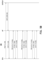
- FIG. 5B shows a variation of the signaling flow 46A of FIG. 5A and is denoted as signaling flow 46B.
- the signaling flow 46A of FIG. 5A shares similarities with the signaling flow 36 of FIG. 4 .
- the signaling flow 46A is still controlled by the AP.
- the data transmission is from the STA to the AP (an UL transmission), versus the data transmission from the AP to the STA (DL transmission) in FIG. 4 .
- the AP may have knowledge of the data traffic pattern, where the data transmission is expected to arrive at the AP in a set of pre-determined time points (with possibly some minor delay variations). For instance, the data transmission may follow a periodic data traffic pattern with a fixed time period between two data packets. As similarly described above for the signaling flow 36 of FIG. 4 , the AP may obtain the information regarding the data traffic pattern in one or a combination of ways. For instance, the AP may determine the policies by itself (e.g., may be the source of the policies). In some embodiments, as reflected by the signaling flow 46B of FIG. 5B , the AP may receive a configuration message 62 (CNFG CMD) that is sent by a WLAN controller.
- CNFG CMD configuration message 62
- the AP may learn of the data traffic pattern in other or additional ways. For instance, the AP may learn of the data traffic pattern from the request 48 sent by the STA.
- the STA sends a request for high-quality uplink service to the AP 48 (RQST UL).
- This signaling message (request 48) informs the AP that in the next few data transmission rounds, the STA expects to report important information and hence a configuration for this type of service is requested.
- the STA informs the AP about the parameters of the expected traffic. For instance, the STA may send this control message to establish the high-quality service for predictable uplink data traffic.
- the control message may include a set of time points of the expected transmission time, an expected size of each data packet, a period of a periodic traffic flow, a starting time of this uplink data flow, an ending time of this uplink data flow, and/or a number of data packets for a periodic data flow.
- the AP responds to the STA with a configuration of the high-quality uplink service 50 (CNFG UL).
- the configuration informs the STA about such parameters as the starting time, period, how long the pre-data transmission phase lasts, etc.
- the STA sends a set of test packets according to a pre-data transmission 52a (PRE-DATA TX in phase1).
- PRE-DATA TX a pre-data transmission 52a
- the STA starts pre-data-transmission procedures before t_i.
- the starting time may be configured as (t_i - T_pre), where T_pre is a configurable parameter for the protocol operation.
- the STA may start channel access contention at (t_i - T_pre). If the channel contention is successful, the STA may become TXOP holder.
- the STA may transmit one or more pre-data-transmission packets, and those pre- data-transmission packets may include a data packet with a small dummy data payload, a data packet with an empty data payload, a Null packet (e.g., Null data PPDU), or a control packet that requests channel state measurements (e.g., a sounding PPDU).
- a Null packet e.g., Null data PPDU
- control packet that requests channel state measurements (e.g., a sounding PPDU).
- the sending of the pre-data packets may elicit a transmission result 54a (e.g., TX RSLT, which may be the presence or absence of an ACK and/or channel feedback) from the AP (e.g., acknowledging that the set of packets were successfully received).
- a transmission result 54a e.g., TX RSLT, which may be the presence or absence of an ACK and/or channel feedback
- the AP may respond with an ACK message and/or conduct channel measurements, and report the channel state information to the STA.
- the AP may respond with an ACK with piggybacked channel state information feedback (or may not respond at all).
- the STA performs rate adaptation (e.g., selection of a better MCS, etc.) based on 52a and 54a. For instance, upon receiving (or not receiving) the ACK message or/and channel state information feedback from the AP, the STA conducts rate adaptation and selects/re-selects the proper transmission configuration (e.g. MCS).
- rate adaptation e.g., selection of a better MCS, etc.
- the STA sends a set of application data packets corresponding to an data transmission 56a (DATA TX) that is based on the rate adaptation performed on the basis of feedback from sending the test data packets.
- the STA may transmit multiple pre-data-transmission packets until the number of transmitted pre-data-transmission packets is equal to an upper limit packet number, N_max, the time used for pre-data-transmission is greater than or equal to a time threshold, T_max, the application data, which is predicted to arrive at time t_i, has arrived at the STA WLAN radio interface, or the STA may (prematurely) terminate the pre-data-transmission phase and start the data transmission.
- phase2 data transmission may be more reliable (than if rate adaptation was performed only during the data transmission phase).
- This two-phase rate adaptation repeats again for the second round of data transmissions (52b, 54b, and 56b) and the third round of data transmissions (52c, 54c, and 56c) in similar manner as performed for the first round of data transmission.
- FIG. 5B shows a variation of the signaling flow of FIG. 5A , with the addition of a controller.
- the AP of FIG. 5A may have functionality of the controller of FIG. 5B embedded within the AP (e.g., co-located), whereas in FIG. 5B , the functionality of the controller is carried out by a device that is separate from the AP.
- One example implementation environment may be an office or area with one or more APs covering/serving one or more wireless devices (e.g., notebooks, tablets, phones, etc.), or a large factory where there are multiple APs to cover a large area.
- the controller and the AP are physically separated, the basic operation as described in association with FIG.
- a request for a high-quality uplink service 60 (RQST UL) is relayed by the AP to a controller (e.g., a WLAN controller within the network).
- the controller may control one or more access points.
- the request 60 may be similar in content (e.g., parameters), and the information it provides to the AP(s), to the request 48 ( FIG. 5A ).
- the controller responds with a configuration command 62 (CNFG CMD) to the AP, which transmits the configuration UL message 64 (CNFG UL, which is similar in content and effect to the configuration UL message 50 in FIG. 5A ) based on the configuration command 62.
- CNFG CMD configuration command 62
- the controller is the source of the configuration of this service. From there, the rounds of transmission are as similarly described in association with FIG. 5A , the discussion of which is omitted here to avoid obfuscating the relevant differences between FIG. 5A and FIG. 5B .
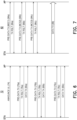
- FIG. 6 shows an example signaling flow 72 for an example STA-controlled uplink (UL) data transmission using an embodiment of the two-phase rate adaptation method.
- the signaling flow 72 is similar to the signaling flow 36 of FIG. 4 , except the arrow directions are all reversed.
- the AP transmits the uplink data transmissions to the STA in the pre-data transmission (e.g., 40a) and data transmission (e.g., 44a) phases.
- the STA transmits the uplink data transmissions to the AP in the pre-data transmission (e.g., 76a (PRE-DATA TX)) and data transmission (e.g., 80a (DATA TX)) phases.
- the signaling flow 72 includes the STA sending to the AP the announcement of high-quality uplink data transmission services 74 (ANNOUNCE UL).
- the announcement 74 e.g., control message
- the STA is a decision maker (as to the configuration) in the signaling flow 72 of FIG. 6 . Compare the signaling flow 72 to the signaling flow 46A of FIG. 5A , where the initiation of the announcement 48 is also from the STA, but the decision maker for the configuration is the AP (or in the signaling flow 46B of FIG. 5B , the decision maker for the configuration is the controller).
- the STA is a generator of those data packets in this instance, and thus it already has knowledge.
- the STA may be a WLAN device that communicates with a notebook or a robot, and the notebook or robot provides important data every, say, 100 msec.
- the WLAN device (STA) has the knowledge of the data traffic pattern.
- the STA may also, or alternatively, obtain the data traffic pattern from preconfigured information, based on the application type in the packet header, based on the address of the destination node, based on the QoS type indicated in packet header, and/or from a configuration message that is sent by an application server.
- the first round of transmissions includes the STA sending a set of test data packets during a pre-data transmission phase (phase1) 76a (PRE-DATA TX).
- the data transmission is expected to be generated at the STA in a set of pre-determined time points (with possibly some minor delay variations), such as periodic data traffic with a given period between two data packets.
- a data packet P_i is expected to generate at STA at time t_i
- the STA starts pre-data-transmission procedures before t_i.
- the starting time might be configured as (t_i - T_pre), where T_pre is a configurable parameter for the protocol operation.
- the STA may start channel access contention at (t_i - T_pre). If the channel contention is successful, the STA may become TXOP holder.
- the STA may transmit one or more pre-data-transmission packets 76a, and a pre- data-transmission packet may be a data packet with a small dummy data payload, a data packet with an empty data payload, a Null packet (e.g., Null data PPDU), or a control packet that requests a channel state measurement (e.g., a sounding PPDU).
- a pre- data-transmission packet may be a data packet with a small dummy data payload, a data packet with an empty data payload, a Null packet (e.g., Null data PPDU), or a control packet that requests a channel state measurement (e.g., a sounding PPDU).
- the AP may respond with a transmission result 78a (TX RSLT, which may include an ACK message and/or conduct channel measurement, or absence thereof), and report the channel state information to the STA.
- TX RSLT transmission result 78a
- the AP may respond with an ACK with piggybacked channel state information feedback.
- the STA performs rate adaptation based on 76a and 78a. For instance, upon receiving the ACK message or/and channel state information feedback from the AP, the STA may conduct link (e.g., rate) adaptation and select/re-select the proper transmission configuration (e.g., MCS, etc.).
- link e.g., rate
- select/re-select the proper transmission configuration e.g., MCS, etc.
- the STA then transmits the application data packets to the AP 80a (DATA TX).
- the STA may transmit multiple pre-data-transmission packets until the number of transmitted pre-data-transmission packets is equal to an upper limit packet number, N_max, the time used for pre-data-transmission is greater than or equal to a time threshold, T_max, the application data, which is predicted to arrive at time t_i, has arrived at the STA WLAN radio interface, or the STA may (prematurely) terminate the pre-data-transmission phase and start the data transmission (e.g., pre-emption).
- the two-phase rate adaptation method described above for the signaling flow 72 is repeated for the second transmission round (76b, 78b, and 80b) and the third transmission round (76c, 78c, and 80c).
- the signaling flow 36 of FIG. 4 about the only difference between the signaling flow 36 of FIG. 4 and the signaling flow 72 of FIG. 6 is which entity initiates or is in control of the two-phase rate adaptation transmissions.
- FIG. 7 shows an example signaling flow 82 for a pre-data transmission phase (phase 1) using plural, different MCS, followed by the data packet transmission phase (phase 2).
- FIGS. 4, 5A , 5B , and 6 illustrate that during the pre-transmission phase, empty (e.g., artificial or non-important) packets are sent out to the receiving device and an attempt or attempts are made to determine an improvement in the MCS, rate, etc.
- the MCS is adjusted based on the success of the transmissions (e.g., if the previous data is well received, then transmission may be made through a higher rate layer). By doing so, rate adaptation is performed earlier than in existing methods, which commence rate adaptation during the data transmission phase.
- FIG. 4 illustrates an example signaling flow 82 for a pre-data transmission phase (phase 1) using plural, different MCS, followed by the data packet transmission phase (phase 2).
- empty (e.g., artificial or non-important) packets are sent out to the receiving device and an attempt or attempts are made to determine an improvement in
- each sequence uses a different MCS, prior to the data transmission phase.
- the MCS of each sequence may differ in, say, aggressiveness in rate, but the rate adaptation strategy is artificial - without regard to the channel conditions. For instance, if there is no ACK for one or more of the sequences, then during the data transmission phase, the MCS used may be more robust (e.g., due to evidence of poorer channel quality where fidelity of transmission may be improved with a slower rate, more robust transmission). On the other hand, if an ACK is received for each sequence, then the data transmission phase may use a transmission at a faster data rate.
- the MCS used during the pre-data transmission phase does not necessarily consider the channel conditions, but rather, is pre-selected.
- the MCS chosen for MCS1 for instance may be considered too aggressive (or too robust) for the current channel conditions, but nevertheless, is attempted anyway.
- the ordering of the MCS sequence may be somewhat randomly selected based on differences in robustness, rate, etc., or in some embodiments, may be pre-selected based on known features or historical performance (e.g., in a previous set of MCS sequences, a better performance was achieved using a particular ordering of the MCS sequences) and/or according to the type of wireless devices.
- the applied MCS sequences may be configured with a control message, determined based on the previous rate adaptation results, determined from most robust to least robust MCS (higher transmission rate), from a higher-rate MCS to a lower-rate MCS, or from the most likely MCS configuration.
- the STA sends a pre-data transmission using a first MCS (MCS1) 84a (PRE-DATA TX (MCS1)), which elicits a transmission result 86a (e.g., TX RSLT, which includes an ACK and/or channel feedback or CSI information, or no response).
- MCS MCS
- MCS2 PRE-DATA TX
- the STA sends a pre-data transmission using a third MCS (MCS3) 84c (PRE-DATA TX (MCS3)), which elicits a transmission result 86c (e.g., TX RSLT, which may include the presence or absence of an ACK and/or channel feedback).
- MCS MCS
- a transmission result 86c e.g., TX RSLT, which may include the presence or absence of an ACK and/or channel feedback.
- TX RSLT transmission result 86c
- a preferred (e.g., best) MCS transmission is selected for the data transmission phase 88.
- the consecutive sequence involving MCS1, MCS2, and then MCS3 depicted in FIG. 7 is one example sequence for illustration, and that different ordering of the sequence or a different number of sequences may be used in some embodiments (e.g., MCS3, MCS2, then MCS1, or MCS1, MCS3, then MCS2, etc.).
- the feedback from the collective MCS sequences e.g., the transmission results, whether channel measurements, or otherwise as described above
- a suitable (e.g., best) MCS for the data transmission phase e.g., best) MCS for the data transmission phase.
- the rate adaptation module used in the STA needs to be aware of this testing strategy since, should there be a poor transmission result for any given sequence (e.g., no ACK received, or a channel quality indicating that the MCS is a poor choice for the channel conditions), the rate adaptation module makes a decision based on the choice of the particular MCS rather than the channel condition.
- FIG. 8 shows an example communication system 90 in which various devices (e.g., WLAN devices and WLAN APs) may implement an embodiment of the two-phase rate adaptation method.
- the communication system 90 comprises one or more controllers 92 (one shown) that is connected (wired, such as via an Ethernet connection) to plural APs 94.
- the controller 92 may have a computer architecture, including one or more processors, memory, and a communication interface coupled to one or more busses.
- the APs 94 in turn are in wireless communication with one or more devices 96, which may include a STA as described above in association with the signaling flows depicted in FIGS. 4-7 .
- the communication system 90 may be implemented in an office or area according to a mixed wired/wireless WLAN communication system, or a smart environment as described above. In some instances, the communication system 90 may be implemented in an office, factory, hospital, research facility, a home, or even a vehicle, as reflected by the types of devices 96 shown in the communication system 90.
- the controller 92 may be standalone server or computer, or generally, computing device, or a network of controllers (e.g., a server farm, a cloud computing environment) that is co-located in a single facility or with functionality distributed among different locales.
- the APs 94 may also include one or a plurality of components, and may include WLAN APs (e.g., IEEE 802.11 AP), router, or devices providing, say, hot spot functionality (e.g., phone, notebook, etc.). Each of the APs 94 may be in wireless communication with one or more devices 96 (e.g., WLAN devices).
- the devices 96 may include a laptop, notebook, tablet, smartphone, and/or entertainment devices (e.g., game controllers), with 802.11 wireless communication capabilities (e.g., equipped with an 802.11 WLAN radio interface), among other example devices.
- the AP 94 denoted as 802.11 AP is shown in wireless communication with plural devices 96 or stations (STAs), including a laptop (802.11 STA1 - 1), a smartphone (802.11 STA1-2) and a game controller (802.11 STA1-3).
- the AP 94 denoted as 802.11 APs is in wireless communication with a single device 96 (e.g., STA), namely a laptop (802.11 STA2-1).
- the AP 94 denoted as 802.11 APn (the n designating an integer number, which in this example is 3 or more) is shown in wireless communication with two devices 96 (a smartphone 802.11 STA3-1 and a game controller 802.11 STA3-2).
- the arrangement and choice of components is merely illustrative of an example communication system 90, and a different quantity or type of components may be used as an environment in which certain embodiments of a two-phase rate adaptation method may be implemented.
- FIG. 9 shows an example computational architecture for a wireless-capable device 98 used in the communication system 90 of FIG. 9 .
- the wireless-capable device 98 may be a computational architecture for any of the AP 94 or device 96.
- the wireless-capable device 98 may include a (non-transitory) memory 100 (MEM), a processor 102 (e.g., PROC, such as a microprocessor or Application Specific Integrated Circuit (ASIC)), and a communication interface 104 (e.g., CMNC INT, such as an 802.11 WLAN radio interface).
- MCMNC non-transitory memory 100
- CMNC INT such as an 802.11 WLAN radio interface
- the memory 100 may be any data storage device that may store a program code 106 (PRGM CODE), accessed and executed by the processor 102. Examples of the memory 100 include but are not limited to read-only memory, flash memory, random-access memory, hard disk, optical data storage device, non-volatile storage unit, non-transitory computer-readable medium (e.g., tangible media), etc. In one embodiment, the memory 100 is embodied as a non-transitory computer readable medium.
- the communication interface 104 may include a transceiver 110 (TRNCVR) that is used to transmit and receive signals (e.g., data, messages and/or packets) according to processing results of the processor 102.
- TRNCVR transceiver 110
- the wireless-capable device 98 comprises a rate adaptation logic or module 108 (RA MOD), with may be software that is comprised of program code 106 (e.g., a device driver), or hardware or a combination of hardware and firmware that resides in the processor 102 (including individual chipsets), or a combination of both.
- the rate adaptation module 108 comprises the functionality of the two-phase rate adaptation method as described herein. In general, the rate adaptation module 108 performs the functionality involved with implementing the pre-data transmission phase (phase1) and the data transmission phase (phase2), including the configuration for rate adaptation (e.g., MCS selection or preselection (e.g., the latter as described in FIG.
- rate adaptation module 108 may be implemented in one or more tables with different setting configurations from which to choose.
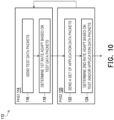
- one embodiment of an example two-phase rate adaptation method comprises the following.
- the method comprises sending a set of test data packets (116), and determining a first rate adaptation configuration based on feedback corresponding to the sending of the set of test data packets (118).
- the method comprises sending a set of application data packets according to the first rate adaptation configuration (122), and determining a second rate adaptation configuration based on at least one of the sending of the set of test data packets or the set of application data packets (124).
Landscapes
- Engineering & Computer Science (AREA)
- Computer Networks & Wireless Communication (AREA)
- Signal Processing (AREA)
- Quality & Reliability (AREA)
- Mobile Radio Communication Systems (AREA)
- Data Exchanges In Wide-Area Networks (AREA)
Applications Claiming Priority (1)
| Application Number | Priority Date | Filing Date | Title |
|---|---|---|---|
| US202363601230P | 2023-11-21 | 2023-11-21 |
Publications (2)
| Publication Number | Publication Date |
|---|---|
| EP4560950A2 true EP4560950A2 (de) | 2025-05-28 |
| EP4560950A3 EP4560950A3 (de) | 2025-09-17 |
Family
ID=93566447
Family Applications (1)
| Application Number | Title | Priority Date | Filing Date |
|---|---|---|---|
| EP24213489.8A Pending EP4560950A3 (de) | 2023-11-21 | 2024-11-18 | Zweiphasen-ratenanpassung für wlan |
Country Status (3)
| Country | Link |
|---|---|
| US (1) | US20250168671A1 (de) |
| EP (1) | EP4560950A3 (de) |
| CN (1) | CN120034911A (de) |
Family Cites Families (6)
| Publication number | Priority date | Publication date | Assignee | Title |
|---|---|---|---|---|
| CA2887651C (en) * | 2012-10-15 | 2017-02-28 | Giwon Park | Method and apparatus for active scanning in wireless lan |
| US9444576B2 (en) * | 2014-05-09 | 2016-09-13 | Qualcomm Incorporated | Updates to MU-MIMO rate adaptation algorithm |
| CN111294852B (zh) * | 2019-03-22 | 2021-08-06 | 展讯通信(上海)有限公司 | 下行多用户数据传输方法及装置、存储介质、终端 |
| US12244417B2 (en) * | 2019-12-20 | 2025-03-04 | Qualcomm Incorporated | Link adaptation protocol in a wireless local area network (WLAN) |
| CN113824533B (zh) * | 2020-06-19 | 2024-09-06 | 南京中兴新软件有限责任公司 | 确定调制编码方式mcs的方法、设备和存储介质 |
| CN115767639B (zh) * | 2021-09-02 | 2025-10-31 | 华为技术有限公司 | 一种数据传输方法及装置 |
-
2024
- 2024-11-18 US US18/950,178 patent/US20250168671A1/en active Pending
- 2024-11-18 CN CN202411647449.7A patent/CN120034911A/zh active Pending
- 2024-11-18 EP EP24213489.8A patent/EP4560950A3/de active Pending
Also Published As
| Publication number | Publication date |
|---|---|
| EP4560950A3 (de) | 2025-09-17 |
| US20250168671A1 (en) | 2025-05-22 |
| CN120034911A (zh) | 2025-05-23 |
Similar Documents
| Publication | Publication Date | Title |
|---|---|---|
| JP7427170B2 (ja) | 時間内及び周波数内rtaパケット重複 | |
| EP4521816B1 (de) | Drahtloskommunikationsverfahren mit verbessertem verteiltem kanalzugriff und drahtloskommunikationsendgerät mit verwendung davon | |
| US8477689B2 (en) | System and methods for distributed medium access control and QOS scheduling in mobile ad-hoc networks | |
| JP5305703B2 (ja) | 無線通信装置、無線通信装置の制御方法、および無線通信装置の制御プログラム | |
| US8553658B2 (en) | Method and apparatus for transmitting data over wireless LAN mesh network | |
| CN110431781B (zh) | 无线电信设备和方法 | |
| JP7330287B2 (ja) | 通信方法および通信装置 | |
| JP5677280B2 (ja) | 無線通信装置および無線通信方法 | |
| CN113875272B (zh) | 实时应用 | |
| JP4718242B2 (ja) | 無線通信装置、無線通信システムおよび無線通信方法 | |
| TW201204146A (en) | Multi-user uplink communication using EDCA with polling | |
| CN114828280B (zh) | 一种数据传输方法和装置 | |
| US7764659B2 (en) | Scheduling method and apparatus for half-duplex transmission | |
| JP2018011285A (ja) | 同時送受信ネットワークモードのための装置および方法 | |
| US10477515B2 (en) | Selective usage of scheduled and unscheduled transmissions to a cellular network | |
| CN101394626A (zh) | 基于无线局域网的分布式业务区分方法和设备 | |
| US8184541B2 (en) | Method and system for link layer scheduling in a multiple access communication system | |
| JP7803403B2 (ja) | 基地局及び無線端末装置 | |
| WO2006106634A1 (ja) | 無線lanシステム、その基地局および端末局 | |
| US20070217443A1 (en) | Communication apparatus, communication method, and computer program product | |
| JP7559828B2 (ja) | 送信局及び受信局 | |
| US20250168671A1 (en) | Two-phase rate adaptation for wlan | |
| JP5653482B2 (ja) | 無線通信装置および無線通信装置の制御方法 | |
| JP5378269B2 (ja) | 無線通信方法、無線基地局、無線アクセスシステム | |
| CN115835290A (zh) | 一种报文传输方法、装置及电子设备和存储介质 |
Legal Events
| Date | Code | Title | Description |
|---|---|---|---|
| PUAI | Public reference made under article 153(3) epc to a published international application that has entered the european phase |
Free format text: ORIGINAL CODE: 0009012 |
|
| STAA | Information on the status of an ep patent application or granted ep patent |
Free format text: STATUS: THE APPLICATION HAS BEEN PUBLISHED |
|
| AK | Designated contracting states |
Kind code of ref document: A2 Designated state(s): AL AT BE BG CH CY CZ DE DK EE ES FI FR GB GR HR HU IE IS IT LI LT LU LV MC ME MK MT NL NO PL PT RO RS SE SI SK SM TR |
|
| PUAL | Search report despatched |
Free format text: ORIGINAL CODE: 0009013 |
|
| AK | Designated contracting states |
Kind code of ref document: A3 Designated state(s): AL AT BE BG CH CY CZ DE DK EE ES FI FR GB GR HR HU IE IS IT LI LT LU LV MC ME MK MT NL NO PL PT RO RS SE SI SK SM TR |
|
| RIC1 | Information provided on ipc code assigned before grant |
Ipc: H04L 1/00 20060101AFI20250813BHEP Ipc: H04W 24/08 20090101ALI20250813BHEP |
|
| STAA | Information on the status of an ep patent application or granted ep patent |
Free format text: STATUS: REQUEST FOR EXAMINATION WAS MADE |
|
| 17P | Request for examination filed |
Effective date: 20260310 |