EP4559618A1 - Machine-outil et procédé d'utilisation d'une telle machine-outil - Google Patents
Machine-outil et procédé d'utilisation d'une telle machine-outil Download PDFInfo
- Publication number
- EP4559618A1 EP4559618A1 EP23212435.4A EP23212435A EP4559618A1 EP 4559618 A1 EP4559618 A1 EP 4559618A1 EP 23212435 A EP23212435 A EP 23212435A EP 4559618 A1 EP4559618 A1 EP 4559618A1
- Authority
- EP
- European Patent Office
- Prior art keywords
- workpiece table
- pivoting
- axis
- support
- pivot
- Prior art date
- Legal status (The legal status is an assumption and is not a legal conclusion. Google has not performed a legal analysis and makes no representation as to the accuracy of the status listed.)
- Pending
Links
Images

Classifications
-
- B—PERFORMING OPERATIONS; TRANSPORTING
- B23—MACHINE TOOLS; METAL-WORKING NOT OTHERWISE PROVIDED FOR
- B23Q—DETAILS, COMPONENTS, OR ACCESSORIES FOR MACHINE TOOLS, e.g. ARRANGEMENTS FOR COPYING OR CONTROLLING; MACHINE TOOLS IN GENERAL CHARACTERISED BY THE CONSTRUCTION OF PARTICULAR DETAILS OR COMPONENTS; COMBINATIONS OR ASSOCIATIONS OF METAL-WORKING MACHINES, NOT DIRECTED TO A PARTICULAR RESULT
- B23Q7/00—Arrangements for handling work specially combined with or arranged in, or specially adapted for use in connection with, machine tools, e.g. for conveying, loading, positioning, discharging, sorting
- B23Q7/02—Arrangements for handling work specially combined with or arranged in, or specially adapted for use in connection with, machine tools, e.g. for conveying, loading, positioning, discharging, sorting by means of drums or rotating tables or discs
-
- B—PERFORMING OPERATIONS; TRANSPORTING
- B23—MACHINE TOOLS; METAL-WORKING NOT OTHERWISE PROVIDED FOR
- B23Q—DETAILS, COMPONENTS, OR ACCESSORIES FOR MACHINE TOOLS, e.g. ARRANGEMENTS FOR COPYING OR CONTROLLING; MACHINE TOOLS IN GENERAL CHARACTERISED BY THE CONSTRUCTION OF PARTICULAR DETAILS OR COMPONENTS; COMBINATIONS OR ASSOCIATIONS OF METAL-WORKING MACHINES, NOT DIRECTED TO A PARTICULAR RESULT
- B23Q39/00—Metal-working machines incorporating a plurality of sub-assemblies, each capable of performing a metal-working operation
- B23Q39/04—Metal-working machines incorporating a plurality of sub-assemblies, each capable of performing a metal-working operation the sub-assemblies being arranged to operate simultaneously at different stations, e.g. with an annular work-table moved in steps
- B23Q39/042—Metal-working machines incorporating a plurality of sub-assemblies, each capable of performing a metal-working operation the sub-assemblies being arranged to operate simultaneously at different stations, e.g. with an annular work-table moved in steps with circular arrangement of the sub-assemblies
- B23Q39/044—Metal-working machines incorporating a plurality of sub-assemblies, each capable of performing a metal-working operation the sub-assemblies being arranged to operate simultaneously at different stations, e.g. with an annular work-table moved in steps with circular arrangement of the sub-assemblies having at least one tool station cooperating with each work holder, e.g. multi-spindle lathes
-
- B—PERFORMING OPERATIONS; TRANSPORTING
- B23—MACHINE TOOLS; METAL-WORKING NOT OTHERWISE PROVIDED FOR
- B23Q—DETAILS, COMPONENTS, OR ACCESSORIES FOR MACHINE TOOLS, e.g. ARRANGEMENTS FOR COPYING OR CONTROLLING; MACHINE TOOLS IN GENERAL CHARACTERISED BY THE CONSTRUCTION OF PARTICULAR DETAILS OR COMPONENTS; COMBINATIONS OR ASSOCIATIONS OF METAL-WORKING MACHINES, NOT DIRECTED TO A PARTICULAR RESULT
- B23Q1/00—Members which are comprised in the general build-up of a form of machine, particularly relatively large fixed members
- B23Q1/25—Movable or adjustable work or tool supports
- B23Q1/64—Movable or adjustable work or tool supports characterised by the purpose of the movement
-
- B—PERFORMING OPERATIONS; TRANSPORTING
- B23—MACHINE TOOLS; METAL-WORKING NOT OTHERWISE PROVIDED FOR
- B23Q—DETAILS, COMPONENTS, OR ACCESSORIES FOR MACHINE TOOLS, e.g. ARRANGEMENTS FOR COPYING OR CONTROLLING; MACHINE TOOLS IN GENERAL CHARACTERISED BY THE CONSTRUCTION OF PARTICULAR DETAILS OR COMPONENTS; COMBINATIONS OR ASSOCIATIONS OF METAL-WORKING MACHINES, NOT DIRECTED TO A PARTICULAR RESULT
- B23Q1/00—Members which are comprised in the general build-up of a form of machine, particularly relatively large fixed members
- B23Q1/25—Movable or adjustable work or tool supports
- B23Q1/44—Movable or adjustable work or tool supports using particular mechanisms
- B23Q1/50—Movable or adjustable work or tool supports using particular mechanisms with rotating pairs only, the rotating pairs being the first two elements of the mechanism
- B23Q1/54—Movable or adjustable work or tool supports using particular mechanisms with rotating pairs only, the rotating pairs being the first two elements of the mechanism two rotating pairs only
- B23Q1/5468—Movable or adjustable work or tool supports using particular mechanisms with rotating pairs only, the rotating pairs being the first two elements of the mechanism two rotating pairs only a single rotating pair followed parallelly by a single rotating pair
-
- B—PERFORMING OPERATIONS; TRANSPORTING
- B23—MACHINE TOOLS; METAL-WORKING NOT OTHERWISE PROVIDED FOR
- B23Q—DETAILS, COMPONENTS, OR ACCESSORIES FOR MACHINE TOOLS, e.g. ARRANGEMENTS FOR COPYING OR CONTROLLING; MACHINE TOOLS IN GENERAL CHARACTERISED BY THE CONSTRUCTION OF PARTICULAR DETAILS OR COMPONENTS; COMBINATIONS OR ASSOCIATIONS OF METAL-WORKING MACHINES, NOT DIRECTED TO A PARTICULAR RESULT
- B23Q39/00—Metal-working machines incorporating a plurality of sub-assemblies, each capable of performing a metal-working operation
- B23Q39/02—Metal-working machines incorporating a plurality of sub-assemblies, each capable of performing a metal-working operation the sub-assemblies being capable of being brought to act at a single operating station
- B23Q39/021—Metal-working machines incorporating a plurality of sub-assemblies, each capable of performing a metal-working operation the sub-assemblies being capable of being brought to act at a single operating station with a plurality of toolheads per workholder, whereby the toolhead is a main spindle, a multispindle, a revolver or the like
- B23Q39/022—Metal-working machines incorporating a plurality of sub-assemblies, each capable of performing a metal-working operation the sub-assemblies being capable of being brought to act at a single operating station with a plurality of toolheads per workholder, whereby the toolhead is a main spindle, a multispindle, a revolver or the like with same working direction of toolheads on same workholder
-
- B—PERFORMING OPERATIONS; TRANSPORTING
- B23—MACHINE TOOLS; METAL-WORKING NOT OTHERWISE PROVIDED FOR
- B23Q—DETAILS, COMPONENTS, OR ACCESSORIES FOR MACHINE TOOLS, e.g. ARRANGEMENTS FOR COPYING OR CONTROLLING; MACHINE TOOLS IN GENERAL CHARACTERISED BY THE CONSTRUCTION OF PARTICULAR DETAILS OR COMPONENTS; COMBINATIONS OR ASSOCIATIONS OF METAL-WORKING MACHINES, NOT DIRECTED TO A PARTICULAR RESULT
- B23Q39/00—Metal-working machines incorporating a plurality of sub-assemblies, each capable of performing a metal-working operation
- B23Q39/02—Metal-working machines incorporating a plurality of sub-assemblies, each capable of performing a metal-working operation the sub-assemblies being capable of being brought to act at a single operating station
- B23Q39/028—Metal-working machines incorporating a plurality of sub-assemblies, each capable of performing a metal-working operation the sub-assemblies being capable of being brought to act at a single operating station with a plurality of workholder per toolhead in operating position
- B23Q39/029—Metal-working machines incorporating a plurality of sub-assemblies, each capable of performing a metal-working operation the sub-assemblies being capable of being brought to act at a single operating station with a plurality of workholder per toolhead in operating position with a twin table for alternatively working on one of the tables
-
- B—PERFORMING OPERATIONS; TRANSPORTING
- B23—MACHINE TOOLS; METAL-WORKING NOT OTHERWISE PROVIDED FOR
- B23Q—DETAILS, COMPONENTS, OR ACCESSORIES FOR MACHINE TOOLS, e.g. ARRANGEMENTS FOR COPYING OR CONTROLLING; MACHINE TOOLS IN GENERAL CHARACTERISED BY THE CONSTRUCTION OF PARTICULAR DETAILS OR COMPONENTS; COMBINATIONS OR ASSOCIATIONS OF METAL-WORKING MACHINES, NOT DIRECTED TO A PARTICULAR RESULT
- B23Q5/00—Driving or feeding mechanisms; Control arrangements therefor
- B23Q5/02—Driving main working members
- B23Q5/04—Driving main working members rotary shafts, e.g. working-spindles
- B23Q5/10—Driving main working members rotary shafts, e.g. working-spindles driven essentially by electrical means
Definitions
- the invention relates to a machine tool with a machine frame, with at least one first work spindle, with at least one second work spindle, with at least one first pivoting support assigned to the first work spindle, which is pivotally mounted in the machine frame about a first pivoting support axis, and which comprises at least one first workpiece table and at least one second workpiece table, wherein the first workpiece table and the second workpiece table are arranged on the first pivoting support on opposite sides of the first pivoting support with respect to the first pivoting support axis and each define an interference region in which they can be arranged or are arranged, and with at least one second pivoting support assigned to the second work spindle, which is pivotally mounted in the machine frame about a second pivoting support axis running parallel to the first pivoting support axis and spaced from the first pivoting support axis, and which comprises at least one first workpiece table and at least one second workpiece table, which are arranged on the second pivoting support on opposite sides of the second pivoting support with respect to the
- Machine tools are known in various designs and configurations from the state of the art. These can, for example, Machine frames include a work table on which workpieces can be removably attached. The workpieces can be machined by a work spindle of the machine tool.
- the work table is loaded with workpieces while the work spindle is idle. Furthermore, the work spindle is idle when the workpieces are removed from the work table after machining. This can result in significant machine tool downtime.
- machine tools are known in which a so-called swivel support is pivotably mounted on the machine frame.
- Two workpiece tables are arranged on opposite sides of the swivel support relative to the swivel support axis.
- a workpiece table is transferred from a work area to a loading area, and simultaneously, the workpiece table located in the loading area is transferred to the work area. This can reduce machine tool downtime.
- swivel supports are known in which two workpiece tables are arranged on each side of the swivel support, with each workpiece table assigned its own work spindle. This requires a distance from the work spindles that allows the swivel support to swivel without collision. As a result, the distance between the swivel support axis and the work spindle is very large, and the machine tool requires a lot of space.
- An object of an embodiment of the invention is to propose a machine tool in which a distance between the pivot support axis and the work spindle is reduced, in particular while maintaining or improving machining times.
- This object is achieved in a machine tool mentioned at the outset in that the interference area of the first workpiece table and/or the interference area of the second workpiece table of the first swivel support projects outwards beyond the swivel area of the first swivel support transversely to the first swivel support axis.
- the machine tool comprises a first swivel support and a second swivel support, each of which includes a first tool table and a second tool table
- the distances between the work spindles and the swivel axes can be kept small. Swiveling two swivel supports, each with a workpiece table on each side, requires a smaller turning circle than a large swivel support with two workpiece tables on each side.
- the interference area of the first workpiece table and/or the interference area of the second workpiece table of the first swivel support extends outward beyond the swivel range of the first swivel support transversely to the first swivel support axis
- the first swivel support can be designed with a smaller swivel range, i.e., with reduced dimensions, while maintaining or improving accessibility through the first work spindle. Furthermore, this ensures that the first workpiece table and/or the second workpiece table can be arranged at a reduced distance from the first work spindle.
- the number of workpieces that can be machined by the machine tool is high.
- first workpiece table and a second workpiece table are arranged on each of the two swivel supports of the machine tool, which are located opposite each other with respect to the swivel support axis.
- "Opposite each other" means that if one of the workpiece tables is arranged on the side of the swivel support facing the work spindle, the other workpiece table is arranged on the side of the swivel support facing away from the work spindle.
- the first pivoting support comprises two first workpiece tables on one side and two second workpiece tables on the other side, which are arranged on opposite sides with respect to the first pivoting support axis.
- the second pivoting support can comprise two first workpiece tables and two second workpiece tables, which are arranged on opposite sides with respect to the second pivoting support axis.
- each swivel support comprising at least three first tool tables and three second tool tables or four first tool tables and four second tool tables, etc.
- the transfer from the first pivot position to the second pivot position may comprise a rotation of 180° about the first pivot axis or second pivot axis.
- the at least one first workpiece table and/or the at least one second workpiece table of the first pivoting support and/or if the at least one first workpiece table and/or the at least one second workpiece table of the second pivoting support are each designed to receive and secure at least one workpiece.
- the workpiece tables can be designed such that more than one workpiece can be arranged thereon.
- the machine tool can be designed to be compact with respect to its extension along the vertical Y-axis if the interference areas of the first workpiece table and/or the second workpiece table of the first swivel support overlap/overlap with the swivel range of the second swivel support when transferring from the first swivel position to the second swivel position and back.
- a distance between the first pivoting support axis and the second pivoting support axis can be reduced than in an arrangement in which the interference areas do not overlap with the pivoting range of the second pivoting support.
- the total extension of the machine tool parallel to a vertical Y-axis can be further reduced if the first pivot support and the second pivot support are arranged without overlapping one another when viewed transversely to the first pivot support axis or if the first pivot support and the second pivot support overlap one another in sections when viewed transversely to the first pivot support axis.
- the first pivot support can be arranged in some areas within the second pivot support, or vice versa.
- the second pivot support can be longer with respect to a horizontally running X-axis than the first pivot support, whereby the latter can be arranged in a recessed area.
- the first pivot support and second pivot support can, for example, be drum-shaped and at their two ends, with respect to the horizontally running X-axis, have a larger radius transverse to the horizontal X-axis than in their intermediate, inner areas.
- one of the pivot supports which is shorter than the other pivot support, can be arranged in these recessed areas.
- a compact design with respect to the vertically extending Y-axis can be further improved if the interference area of the first workpiece table and/or the interference area of the second workpiece table of the second swivel support projects/project beyond the swivel range of the second swivel support transversely to the second swivel support axis and overlaps/overlaps with the swivel range of the first swivel support when transferring from the first swivel position to the second swivel position and back.
- first workpiece table and/or the second workpiece table with its interference areas overlaps with the second pivot support when transferred from the first pivot position to the second pivot position and the first workpiece table and/or the second workpiece table of the second pivot support overlaps with the first pivot support when transferred from the first pivot position to the second pivot position, a particularly compact design of the machine tool with respect to the vertically extending Y-axis can be realized.
- the first workpiece table of the first swivel carrier when it is moved from the first swivel position to the second swivel position, is arranged at any location on the machine tool.
- embodiments of the machine tool are also conceivable in which a third workpiece table and/or a fourth workpiece table are additionally provided, wherein the first workpiece table, second workpiece table, third workpiece table and fourth workpiece table are arranged uniformly with respect to the first pivot support axis and a transfer from the first pivot position to the second pivot position takes place in a carousel-like manner.
- the machine tool comprises one or more first workpiece tables and one or more second workpiece tables on a swivel support.
- the respective second workpiece table is arranged in a loading area, and/or if, in the second pivoting position of the first pivoting support and/or in the second pivoting position of the second pivoting support, the respective first workpiece table is arranged in the loading area.
- the first workpiece table and/or the second workpiece table of the first swivel support and/or the second swivel support are each fixed to their swivel support in a rotationally fixed manner.
- first workpiece table of the first swivel support is pivotably mounted about a first workpiece table axis running parallel to the first swivel support axis
- second workpiece table of the first swivel support is pivotably mounted about a second workpiece table axis running parallel to the first swivel support axis
- the pivoting ranges of the first workpiece table and the second workpiece table form the respective interference areas of the first workpiece table and the second workpiece table, respectively, and/or that the first workpiece table of the second swivel support is pivotably mounted about a first workpiece table axis running parallel to the second swivel support axis
- the second workpiece table of the second swivel support is pivotably mounted about a second workpiece table axis running parallel to the second swivel support axis, wherein the pivoting ranges of
- first swivel support can be arranged in a first release position in which the first workpiece table and the second workpiece table can be arranged in a position and/or orientation in which the second swivel support with its first workpiece table and its second workpiece table can be transferred collision-free from the first swivel position to the second swivel position and vice versa and/or if the second swivel support can be arranged in a second release position in which the first workpiece table and the second workpiece table can be arranged in a position and/or orientation in which the first swivel support with its first workpiece table and its second workpiece table can be transferred collision-free from the first swivel position to the second swivel position and vice versa and/or if the second swivel support can be arranged in a second release position in which the first workpiece table and the second workpiece table can be arranged in a position and/or orientation in which the first swivel support with
- the transfer of the first pivoting support into the first release position, or of the second pivoting support into the second release position can in principle be carried out in any desired manner. It proves to be advantageous if the transfer of the first pivoting support into the first release position comprises rotating or pivoting the first pivoting support about the first pivoting support axis and/or rotating or pivoting the first workpiece table about the first workpiece table axis and/or the second workpiece table about the second workpiece table axis and/or if the transfer of the second pivoting support into the second release position comprises rotating or pivoting the second pivoting support about the second pivoting support axis and/or rotating or pivoting the first workpiece table about the first workpiece table axis and/or the second workpiece table about the second workpiece table axis.
- the transfer into the first release position or into the second release position exclusively comprises a transfer of the first pivot support by rotating or pivoting about the first pivot support axis or of the second pivot support with a rotation or pivoting about the second pivot support axis.
- first workpiece tables and/or the second workpiece tables are each rotatable about the first workpiece table axis or second workpiece table axis, they can be rotated exclusively or in addition to the rotation about the first swivel support axis or second swivel support axis additionally about their own workpiece table axis.
- Embodiments of the workpiece machine are conceivable in which the first pivoting support and the second pivoting support are decoupled in an independent operating mode with respect to their kinematics, can be transferred separately and independently of one another into the first pivoting position, into the second pivoting position, into the first release position and/or the second release position and/or in which the first pivoting support and the second pivoting support are coupled in a dependent operating mode with respect to their kinematics, can be transferred jointly and simultaneously into the first pivoting position, into the second pivoting position, into the first release position and/or the second release position.
- each swivel support can be assigned its own drive unit.
- first swivel support and the second swivel support can be transferred into the individual positions in a dependent operating mode, a common drive can be assigned to the first swivel support and the second swivel support, by means of which both swivel supports can be moved in a coupled manner.
- first pivot support axis and the second pivot support axis running parallel to the first pivot support axis run parallel to a horizontally running X-axis
- first pivot support axis and the second pivot support axis are spaced apart from one another with respect to a vertically running Y-axis, in particular are arranged one above the other with respect to the vertically running Y-axis and in particular are aligned with one another with respect to the vertical Y-axis running transversely thereto
- first pivot support axis and the second pivot support axis running parallel to the first pivot support axis run parallel to a vertically running Y-axis
- first pivot support axis and the second pivot support axis are spaced apart from one another with respect to a horizontally running X-axis, in particular are arranged next to one another with respect to the horizontally running X-axis are arranged and are aligned with each other in particular with respect
- first pivot support axis and the second pivot support axis as well as the first workpiece table axes and the second workpiece table axes run parallel to one another and parallel to the horizontally extending X-axis or that the first pivot support axis, the second pivot support axis as well as the first workpiece table axes and the second workpiece table axes run parallel to one another and parallel to the vertically extending Y-axis.
- the first spindle axis of the first work spindle and/or the second spindle axis of the second work spindle can run transversely to both spatial orientations of the swivel support axes and the associated workpiece table axes.
- the machine tool can be designed to be compact in terms of its spatial dimensions if, in the first pivoting position and in the second pivoting position, the first workpiece table and the second workpiece table of a pivoting support are each arranged point-symmetrically to one another with respect to the associated pivoting support axis of the respective pivoting support on which they are arranged, and if the respective pivoting support axis runs horizontally, the first workpiece table and the second workpiece table are arranged offset from one another with respect to a vertical axis and, in particular, the pivoting ranges of the first workpiece table and the second workpiece table of the associated pivoting support overlap with a vertical plane running through the pivoting support axis, and if the respective pivoting support axis runs vertically, the first workpiece table and the second workpiece table are arranged offset from one another with respect to a horizontal axis and, in particular, the pivoting ranges of the first workpiece table and the second workpiece table of the associated pivoting support overlap with a horizontal plane running through the pivoting support axi
- first work spindle and/or second work spindle and the first swivel support axis or second swivel support axis can be reduced.
- This interlaced arrangement can be achieved, for example, if the distance between the first workpiece tables and the swivel axis in the first swivel position is smaller than the maximum possible.
- the swivel ranges of the first workpiece tables and the swivel ranges of the second workpiece tables assigned to the first workpiece tables can overlap each other.
- the respective workpiece table axes can be offset from one another with respect to a transverse axis. For example, if the respective workpiece table axes run parallel to a horizontal X-axis, the first workpiece table axis is offset from the second workpiece table axis with respect to a vertical Y-axis.
- first workpiece table axis and the second workpiece table axis are arranged parallel to a vertically extending Y-axis, these can be arranged offset from one another with respect to the horizontal X-axis running transversely thereto when they are fixed to the pivot support in an overlapping manner.
- the distance between the first swivel support axis and the first tool table axis is smaller than the interference area of the first workpiece table and/or the distance between the first swivel support axis and the second workpiece table axis is smaller than the interference area of the second workpiece table.
- the distance between the second swivel support axis and the first workpiece table axis can be smaller than the interference circle of the first workpiece table and/or the distance between the second swivel support axis and the second workpiece table axis must be smaller than the interference area of the second workpiece table.
- the at least one first work spindle can be mounted for rotation about a first spindle axis and/or the at least one second work spindle can be mounted for rotation about a second spindle axis.
- the first spindle axis and/or the second spindle axis can run parallel to a horizontally extending Z-axis, which runs transversely to the vertically extending Y-axis and transversely to the horizontally extending X-axis.
- first work spindle and the second work spindle are arranged vertically one above the other when the first pivot support axis and the second pivot support axis running parallel to the first pivot support axis run parallel to the horizontally running X-axis, and that the first work spindle and the second work spindle are arranged horizontally next to each other when the first pivot support axis and the second pivot support axis running parallel to the first pivot support axis run parallel to the vertically running Y-axis.
- the first pivoting support comprises a first partition wall by which the first workpiece table and the second workpiece table are spatially separated from one another in the first pivoting position and in the second pivoting position and the loading area is completely or at least partially shielded from the work area and/or if the second pivoting support comprises a second partition wall by which the first workpiece table and the second workpiece table are spatially separated from one another in the first pivoting position and in the second pivoting position and the loading area is completely or at least partially shielded from the work area.
- an operator of the machine tool is shielded from the working area by the first partition wall and/or the second partition wall when accessing the loading area.
- the working area can extend over both the first pivot support and the second pivot support.
- the first pivot support comprises a first working area and the second pivot support comprises a second working area, which are spatially separated from one another.
- the first pivoting support may comprise a first loading area and the second pivoting support may comprise a second loading area, which are spatially separated from one another.
- the machine tool can be implemented in a simplified manner if a common working area and a common loading area are assigned to the first swivel carrier and the second swivel carrier.
- first partition wall of the first pivot support is flexible and/or elastically bendable about an axis running parallel to the first pivot support axis and/or that the second partition wall of the second pivot support is flexible and/or elastically bendable about an axis running parallel to the second pivot support axis.
- first pivot support In principle, it is conceivable for the first pivot support to be arranged directly adjacent to the second pivot support without gaps and/or joints. This allows the machine tool to be designed with reduced installation space in terms of its dimensions.
- the machine frame comprises at least one separating section which is arranged between the first pivot support and the second pivot support, wherein the first partition wall of the first pivot support, the separating section of the machine frame and the second partition wall of the second pivot support in the first pivot position and in the second pivot position spatially separate the working area from the loading area from one another in whole or at least in sections, without gaps and/or joints.
- the transfer of the first pivoting support into the first release position comprises a rotation of the first pivoting support about the first pivoting support axis and/or a rotation or pivoting of the first workpiece table about the first workpiece table axis and/or of the second workpiece table about the second workpiece table axis and/or if the transfer of the second pivoting support into the second release position comprises a rotation of the second pivoting support about the second pivoting support axis and/or a rotation or pivoting of the first workpiece table about the first workpiece table axis and/or of the second workpiece table about the second workpiece table axis.
- Figure 1 shows an embodiment of a machine tool designated overall by reference numeral 2.
- the machine tool 2 comprises a machine frame 4, a first work spindle 6, and a second work spindle 8.
- the machine tool 2 comprises a first pivot support 10 assigned to the first work spindle 6, which is pivotally mounted in the machine frame 4 about a first pivot support axis 12 and which comprises a first workpiece table 14 and a second workpiece table 16.
- the first workpiece table 14 and the second workpiece table 16 are arranged on the first pivot support 10 on opposite sides with respect to the first pivot support axis 12. They each define an interference zone in which they can be arranged or are arranged.
- the first workpiece table 14 of the first pivot support 10 is rotatably mounted on the first pivot support 10 about a first workpiece table axis 15, and the second workpiece table 16 is rotatably mounted about a second workpiece table axis 17.
- the machine tool 2 comprises a second pivot support 20 assigned to the second work spindle 8, which is pivotally mounted in the machine frame 4 about a second pivot support axis 22 running parallel to the first pivot support axis 12 and spaced from the first pivot support axis 12.
- the second pivot support 20 also comprises a first workpiece table 24 and a second workpiece table 26.
- the first workpiece table 24 and the second workpiece table 26 are arranged on the second pivot support 20 on opposite sides with respect to the second pivot support axis 22.
- the first workpiece table 24 is rotatable on the second pivot support 20 about a first workpiece table axis 25 and the second workpiece table 26 about a second workpiece table axis 27.
- the first workpiece table 24 and the second workpiece table 26 of the second pivoting support 20 also each define interference areas in which they can be arranged or are arranged.
- the first pivot support 10 and the second pivot support 20 are each from a first pivot position ( Figure 1 ), in which the respective first workpiece table 14, 24 is arranged in a working area and the first work spindle 6, or the second Work spindle 8 are accessible, can be transferred into a second pivoting position in which the second workpiece table 16, 26 is arranged on the working area 28 and is accessible to the first work spindle 6 or the second work spindle 8.
- the respective first workpiece tables 14, 24 when moving from the first pivoting position to the second pivoting position, can be moved from the working area 28 into a loading area 30, in which the workpiece tables 14, 16, 24, 26 can be loaded with workpieces.
- first workpiece tables 14, 24 and the second workpiece tables 16, 26 are designed such that their interference areas each project outwards beyond their pivot support 10, 20 transversely to the pivot support axis 12, 22 of the respective pivot support 10, 20.
- first pivot support 10 and the second pivot support 20 are arranged in such a way that they are arranged one above the other and in alignment with one another with respect to a vertically extending Y-axis, and their respective pivot ranges are arranged directly adjacent to one another.
- the interference areas of the first workpiece table 14 and the second workpiece table 16 of the first pivot support 10 extend at least partially into the pivot range of the second pivot support 20 when the workpiece table is transferred from the first pivot position to the second pivot position and vice versa.
- the interference areas of the first workpiece table 24 and the second workpiece table 26 of the second pivot support 20 extend into the pivot range of the first pivot support 10 when the second pivot support is transferred from the first pivot position to the second pivot position or vice versa.
- the first pivoting support 10 can be arranged in a first release position in which the first workpiece table 14 and the second workpiece table 16 can be arranged in a position and/or orientation in which the second pivoting support 20 with its first workpiece table 24 and its second workpiece table 26 can be moved collision-free from the first pivoting position to the second Pivoting position and vice versa.
- the second pivoting support 20 can be arranged in a second release position in which the first workpiece table 24 and the second workpiece table 26 can be arranged in a position and/or orientation in which the first pivoting support 10 with its first workpiece table 14 and its second workpiece table 16 can be transferred from the first pivoting position to the second pivoting position and back without collision.
- the swivel support 10 can be rotated about the first swivel support axis 12.
- the first workpiece table 14 can be rotated about the first workpiece table axis 15 and/or the second workpiece table 16 can be rotated about the second workpiece table axis 17.
- first pivot support axis 12, the second pivot support axis 22, the first workpiece table axes 15, 25 and the second workpiece table axes 17, 27 run parallel to one another and parallel to a horizontally running X-axis.
- the first work spindle 6 and the second work spindle 8 are arranged offset from one another in the vertical direction with respect to a vertically running Y-axis and one above the other, in particular in alignment with one another.
- the first work spindle 6 is mounted for rotation about a first spindle axis 32 and the second work spindle 8 is mounted for rotation about a second spindle axis 34.
- the first spindle axis 32 and the second spindle axis 34 run parallel to a horizontally running Z-axis. This runs transversely to the horizontally running X-axis with the vertically running Y-axis.
- Figure 1 shows an embodiment of the machine tool 2, in which the first pivoting support 10 and the second pivoting support 20 are transferred in an interlaced arrangement, which forms the first pivoting position and the second pivoting position, respectively.
- the first workpiece table 14, 24 and the second workpiece table 16, 26 of a pivoting support 10, 20 are each with respect to the associated swivel support axis 12, 22 of the respective swivel support 10, 20 on which they are arranged, are arranged point-symmetrically to one another.
- the respective first workpiece table 14, 24 and the second workpiece table 16, 26 are arranged offset from one another with respect to a vertically running Y-axis.
- a distance of the first workpiece table axis 15 and the second workpiece table axis 17 from the first swivel support axis 12 is reduced, as is a distance of the first workpiece table axis 25 and the second workpiece table axis 27 from the second swivel support axis 22.
- a distance of the first work spindle 6 from the first swivel support axis 12 and a distance of the second work spindle 8 from the second swivel support axis 22 is also reduced.
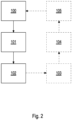
- Figure 2 shows a schematic flow diagram of an embodiment of a method according to the invention for operating a machine tool 2.
- the first pivoting support 10 is transferred from the first pivoting position or from the second pivoting position into a first release position in which the first workpiece table 14 and the second workpiece table 16 are arranged in a position and/or orientation in which the second pivoting support 20 with its first workpiece table 24 and its second workpiece table 26 can be transferred from the first pivoting position into the second pivoting position and vice versa without collision with the first pivoting support 10.
- the second pivot support 20 is transferred from the first pivot position to the second pivot position or from the second pivot position to the first pivot position.
- the first pivot support 10 is transferred from the first release position back into the first pivot position or into the second pivot position.
- the second pivot support 20 can be moved from the first pivot position or from the second Pivoting position into a second release position in which the first workpiece table 24 and the second workpiece table 26 are arranged in a position and/or orientation in which the first pivoting support 10 with its first workpiece table 14 and its second workpiece table 16 can be transferred from the first pivoting position into the second pivoting position and vice versa without collision with respect to the second pivoting support 20.
- the first pivot support 10 is transferred from the first pivot position to the second pivot position or from the second pivot position to the first pivot position.
- the second pivot support 20 is transferred from the second release position back into the first pivot position or into the second pivot position.
- the work tables 14, 16, 24, 26 now arranged in the work area 28 can be machined and the work tables 14, 16, 24, 26 arranged in the loading area 30 can be loaded.
Landscapes
- Engineering & Computer Science (AREA)
- Mechanical Engineering (AREA)
- Machine Tool Units (AREA)
Priority Applications (3)
| Application Number | Priority Date | Filing Date | Title |
|---|---|---|---|
| EP23212435.4A EP4559618A1 (fr) | 2023-11-27 | 2023-11-27 | Machine-outil et procédé d'utilisation d'une telle machine-outil |
| US18/953,828 US20250170682A1 (en) | 2023-11-27 | 2024-11-20 | Machine tool and method to operate this type of machine tool |
| CN202411692339.2A CN120038573A (zh) | 2023-11-27 | 2024-11-25 | 机床和用于运行这样的机床的方法 |
Applications Claiming Priority (1)
| Application Number | Priority Date | Filing Date | Title |
|---|---|---|---|
| EP23212435.4A EP4559618A1 (fr) | 2023-11-27 | 2023-11-27 | Machine-outil et procédé d'utilisation d'une telle machine-outil |
Publications (1)
| Publication Number | Publication Date |
|---|---|
| EP4559618A1 true EP4559618A1 (fr) | 2025-05-28 |
Family
ID=88975930
Family Applications (1)
| Application Number | Title | Priority Date | Filing Date |
|---|---|---|---|
| EP23212435.4A Pending EP4559618A1 (fr) | 2023-11-27 | 2023-11-27 | Machine-outil et procédé d'utilisation d'une telle machine-outil |
Country Status (3)
| Country | Link |
|---|---|
| US (1) | US20250170682A1 (fr) |
| EP (1) | EP4559618A1 (fr) |
| CN (1) | CN120038573A (fr) |
Citations (3)
| Publication number | Priority date | Publication date | Assignee | Title |
|---|---|---|---|---|
| US20150165576A1 (en) * | 2012-08-23 | 2015-06-18 | Chiron-Werke Gmbh & Co. Kg | Workpiece changer |
| EP3017910A2 (fr) * | 2014-09-30 | 2016-05-11 | SK-Technologies UG | Table tournante |
| EP3715051A2 (fr) * | 2020-07-24 | 2020-09-30 | Fill Gesellschaft m.b.H. | Machine-outil et procédé de fonctionnement de la machine-outil |
-
2023
- 2023-11-27 EP EP23212435.4A patent/EP4559618A1/fr active Pending
-
2024
- 2024-11-20 US US18/953,828 patent/US20250170682A1/en active Pending
- 2024-11-25 CN CN202411692339.2A patent/CN120038573A/zh active Pending
Patent Citations (3)
| Publication number | Priority date | Publication date | Assignee | Title |
|---|---|---|---|---|
| US20150165576A1 (en) * | 2012-08-23 | 2015-06-18 | Chiron-Werke Gmbh & Co. Kg | Workpiece changer |
| EP3017910A2 (fr) * | 2014-09-30 | 2016-05-11 | SK-Technologies UG | Table tournante |
| EP3715051A2 (fr) * | 2020-07-24 | 2020-09-30 | Fill Gesellschaft m.b.H. | Machine-outil et procédé de fonctionnement de la machine-outil |
Also Published As
| Publication number | Publication date |
|---|---|
| CN120038573A (zh) | 2025-05-27 |
| US20250170682A1 (en) | 2025-05-29 |
Similar Documents
| Publication | Publication Date | Title |
|---|---|---|
| EP2714307B1 (fr) | Machine-outil | |
| EP2714310B1 (fr) | Machine-outil | |
| DE3035451C2 (fr) | ||
| EP2714308B1 (fr) | Machine-outil | |
| DE60303672T2 (de) | Werkzeugmaschine | |
| DE4446475C2 (de) | Verfahren und Maschine zum Bearbeiten von Werkstücken | |
| EP2762254B1 (fr) | Tour à vilebrequins et fraiseuse | |
| EP1409182B1 (fr) | Machine-outil | |
| WO2018172061A1 (fr) | Machine-outil comportant deux arbres d'outil | |
| EP2344301B1 (fr) | Machine-outil | |
| DE69603908T2 (de) | Werkzeugmaschine zum Bearbeiten von länglichen Elementen mit als Ausleger montierten Werkstückträgern | |
| EP1927429A1 (fr) | Machine-outil avec magasin à outils | |
| EP0154349B1 (fr) | Dispositif pour changer des outils ou des objets similaires dans la broche d'une machine-outil | |
| DE19800034C2 (de) | Werkzeugmaschine für Bearbeitungswerkzeuge aus der Gruppe Schleifkörper und Fräser | |
| EP1575737A1 (fr) | Machine-outil pourvue d'un module de remplacement de palettes | |
| EP1511596B1 (fr) | Tour multibroche | |
| DE102004044186A1 (de) | Bearbeitungszentrum | |
| EP0331178A1 (fr) | Construction compacte d'une perceuse sur colonne | |
| EP4559618A1 (fr) | Machine-outil et procédé d'utilisation d'une telle machine-outil | |
| EP1074333B1 (fr) | Tour avec deux systèmes de support d'outils | |
| AT521951B1 (de) | Werkzeugmaschine | |
| EP1736264A1 (fr) | Dispositif pour l'usinage intérieur de pièces, en particulier de carters d'engrenages différentiels | |
| DE102007043421A1 (de) | Werkzeugmaschine | |
| EP1291101B1 (fr) | Machine-outil avec broche porte-pièce et porte-outil multiple | |
| EP4556161A1 (fr) | Machine-outil |
Legal Events
| Date | Code | Title | Description |
|---|---|---|---|
| PUAI | Public reference made under article 153(3) epc to a published international application that has entered the european phase |
Free format text: ORIGINAL CODE: 0009012 |
|
| STAA | Information on the status of an ep patent application or granted ep patent |
Free format text: STATUS: REQUEST FOR EXAMINATION WAS MADE |
|
| 17P | Request for examination filed |
Effective date: 20231127 |
|
| AK | Designated contracting states |
Kind code of ref document: A1 Designated state(s): AL AT BE BG CH CY CZ DE DK EE ES FI FR GB GR HR HU IE IS IT LI LT LU LV MC ME MK MT NL NO PL PT RO RS SE SI SK SM TR |
|
| GRAP | Despatch of communication of intention to grant a patent |
Free format text: ORIGINAL CODE: EPIDOSNIGR1 |
|
| STAA | Information on the status of an ep patent application or granted ep patent |
Free format text: STATUS: GRANT OF PATENT IS INTENDED |
|
| INTG | Intention to grant announced |
Effective date: 20250929 |
|
| GRAS | Grant fee paid |
Free format text: ORIGINAL CODE: EPIDOSNIGR3 |
|
| GRAA | (expected) grant |
Free format text: ORIGINAL CODE: 0009210 |
|
| STAA | Information on the status of an ep patent application or granted ep patent |
Free format text: STATUS: THE PATENT HAS BEEN GRANTED |