EP4559420A2 - Fusing and cutting surgical instrument - Google Patents
Fusing and cutting surgical instrument Download PDFInfo
- Publication number
- EP4559420A2 EP4559420A2 EP25168900.6A EP25168900A EP4559420A2 EP 4559420 A2 EP4559420 A2 EP 4559420A2 EP 25168900 A EP25168900 A EP 25168900A EP 4559420 A2 EP4559420 A2 EP 4559420A2
- Authority
- EP
- European Patent Office
- Prior art keywords
- surgical instrument
- jaws
- wrist
- end effector
- cutting element
- Prior art date
- Legal status (The legal status is an assumption and is not a legal conclusion. Google has not performed a legal analysis and makes no representation as to the accuracy of the status listed.)
- Pending
Links
Images







Classifications
-
- A—HUMAN NECESSITIES
- A61—MEDICAL OR VETERINARY SCIENCE; HYGIENE
- A61B—DIAGNOSIS; SURGERY; IDENTIFICATION
- A61B18/00—Surgical instruments, devices or methods for transferring non-mechanical forms of energy to or from the body
- A61B18/04—Surgical instruments, devices or methods for transferring non-mechanical forms of energy to or from the body by heating
- A61B18/12—Surgical instruments, devices or methods for transferring non-mechanical forms of energy to or from the body by heating by passing a current through the tissue to be heated, e.g. high-frequency current
- A61B18/14—Probes or electrodes therefor
- A61B18/1442—Probes having pivoting end effectors, e.g. forceps
- A61B18/1445—Probes having pivoting end effectors, e.g. forceps at the distal end of a shaft, e.g. forceps or scissors at the end of a rigid rod
-
- A—HUMAN NECESSITIES
- A61—MEDICAL OR VETERINARY SCIENCE; HYGIENE
- A61B—DIAGNOSIS; SURGERY; IDENTIFICATION
- A61B17/00—Surgical instruments, devices or methods
- A61B17/00234—Surgical instruments, devices or methods for minimally invasive surgery
-
- A—HUMAN NECESSITIES
- A61—MEDICAL OR VETERINARY SCIENCE; HYGIENE
- A61B—DIAGNOSIS; SURGERY; IDENTIFICATION
- A61B18/00—Surgical instruments, devices or methods for transferring non-mechanical forms of energy to or from the body
- A61B18/04—Surgical instruments, devices or methods for transferring non-mechanical forms of energy to or from the body by heating
- A61B18/12—Surgical instruments, devices or methods for transferring non-mechanical forms of energy to or from the body by heating by passing a current through the tissue to be heated, e.g. high-frequency current
- A61B18/14—Probes or electrodes therefor
- A61B18/1482—Probes or electrodes therefor having a long rigid shaft for accessing the inner body transcutaneously in minimal invasive surgery, e.g. laparoscopy
-
- A—HUMAN NECESSITIES
- A61—MEDICAL OR VETERINARY SCIENCE; HYGIENE
- A61B—DIAGNOSIS; SURGERY; IDENTIFICATION
- A61B34/00—Computer-aided surgery; Manipulators or robots specially adapted for use in surgery
- A61B34/30—Surgical robots
-
- A—HUMAN NECESSITIES
- A61—MEDICAL OR VETERINARY SCIENCE; HYGIENE
- A61B—DIAGNOSIS; SURGERY; IDENTIFICATION
- A61B34/00—Computer-aided surgery; Manipulators or robots specially adapted for use in surgery
- A61B34/70—Manipulators specially adapted for use in surgery
- A61B34/71—Manipulators operated by drive cable mechanisms
-
- A—HUMAN NECESSITIES
- A61—MEDICAL OR VETERINARY SCIENCE; HYGIENE
- A61B—DIAGNOSIS; SURGERY; IDENTIFICATION
- A61B17/00—Surgical instruments, devices or methods
- A61B17/00234—Surgical instruments, devices or methods for minimally invasive surgery
- A61B2017/00292—Surgical instruments, devices or methods for minimally invasive surgery mounted on or guided by flexible, e.g. catheter-like, means
- A61B2017/003—Steerable
- A61B2017/00318—Steering mechanisms
- A61B2017/00323—Cables or rods
-
- A—HUMAN NECESSITIES
- A61—MEDICAL OR VETERINARY SCIENCE; HYGIENE
- A61B—DIAGNOSIS; SURGERY; IDENTIFICATION
- A61B17/00—Surgical instruments, devices or methods
- A61B2017/00477—Coupling
-
- A—HUMAN NECESSITIES
- A61—MEDICAL OR VETERINARY SCIENCE; HYGIENE
- A61B—DIAGNOSIS; SURGERY; IDENTIFICATION
- A61B18/00—Surgical instruments, devices or methods for transferring non-mechanical forms of energy to or from the body
- A61B2018/00053—Mechanical features of the instrument of device
- A61B2018/00059—Material properties
- A61B2018/00071—Electrical conductivity
- A61B2018/00083—Electrical conductivity low, i.e. electrically insulating
-
- A—HUMAN NECESSITIES
- A61—MEDICAL OR VETERINARY SCIENCE; HYGIENE
- A61B—DIAGNOSIS; SURGERY; IDENTIFICATION
- A61B18/00—Surgical instruments, devices or methods for transferring non-mechanical forms of energy to or from the body
- A61B2018/00571—Surgical instruments, devices or methods for transferring non-mechanical forms of energy to or from the body for achieving a particular surgical effect
- A61B2018/00607—Coagulation and cutting with the same instrument
-
- A—HUMAN NECESSITIES
- A61—MEDICAL OR VETERINARY SCIENCE; HYGIENE
- A61B—DIAGNOSIS; SURGERY; IDENTIFICATION
- A61B18/00—Surgical instruments, devices or methods for transferring non-mechanical forms of energy to or from the body
- A61B2018/00571—Surgical instruments, devices or methods for transferring non-mechanical forms of energy to or from the body for achieving a particular surgical effect
- A61B2018/0063—Sealing
-
- A—HUMAN NECESSITIES
- A61—MEDICAL OR VETERINARY SCIENCE; HYGIENE
- A61B—DIAGNOSIS; SURGERY; IDENTIFICATION
- A61B18/00—Surgical instruments, devices or methods for transferring non-mechanical forms of energy to or from the body
- A61B2018/00982—Surgical instruments, devices or methods for transferring non-mechanical forms of energy to or from the body combined with or comprising means for visual or photographic inspections inside the body, e.g. endoscopes
-
- A—HUMAN NECESSITIES
- A61—MEDICAL OR VETERINARY SCIENCE; HYGIENE
- A61B—DIAGNOSIS; SURGERY; IDENTIFICATION
- A61B18/00—Surgical instruments, devices or methods for transferring non-mechanical forms of energy to or from the body
- A61B18/04—Surgical instruments, devices or methods for transferring non-mechanical forms of energy to or from the body by heating
- A61B18/12—Surgical instruments, devices or methods for transferring non-mechanical forms of energy to or from the body by heating by passing a current through the tissue to be heated, e.g. high-frequency current
- A61B18/14—Probes or electrodes therefor
- A61B18/1442—Probes having pivoting end effectors, e.g. forceps
- A61B2018/1452—Probes having pivoting end effectors, e.g. forceps including means for cutting
-
- A—HUMAN NECESSITIES
- A61—MEDICAL OR VETERINARY SCIENCE; HYGIENE
- A61B—DIAGNOSIS; SURGERY; IDENTIFICATION
- A61B18/00—Surgical instruments, devices or methods for transferring non-mechanical forms of energy to or from the body
- A61B18/04—Surgical instruments, devices or methods for transferring non-mechanical forms of energy to or from the body by heating
- A61B18/12—Surgical instruments, devices or methods for transferring non-mechanical forms of energy to or from the body by heating by passing a current through the tissue to be heated, e.g. high-frequency current
- A61B18/14—Probes or electrodes therefor
- A61B18/1442—Probes having pivoting end effectors, e.g. forceps
- A61B2018/1452—Probes having pivoting end effectors, e.g. forceps including means for cutting
- A61B2018/1455—Probes having pivoting end effectors, e.g. forceps including means for cutting having a moving blade for cutting tissue grasped by the jaws
-
- A—HUMAN NECESSITIES
- A61—MEDICAL OR VETERINARY SCIENCE; HYGIENE
- A61B—DIAGNOSIS; SURGERY; IDENTIFICATION
- A61B34/00—Computer-aided surgery; Manipulators or robots specially adapted for use in surgery
- A61B34/30—Surgical robots
- A61B2034/305—Details of wrist mechanisms at distal ends of robotic arms
- A61B2034/306—Wrists with multiple vertebrae
Definitions
- aspects of the present disclosure relate to surgical instruments that are minimally invasive and integrate into a single device the use of energy to fuse tissue and a component that cuts the fused tissue. More particularly, aspects of the present disclosure relate to such devices that have an articulating wrist mechanism that supports a surgical instrument end effector configured to cut and fuse tissue.
- tissue e.g., a tissue bundle
- electrosurgical energy is passed between the electrodes in order to fuse the tissues together.
- An example of such tissues includes the opposing walls of a blood vessel.
- the blood vessel can be fused closed, resulting in a sealing of the vessel at the fused region.
- Surgical instruments that perform this action are often referred to as sealing instruments (e.g., a "vessel sealer").
- sealing instruments e.g., a "vessel sealer"
- Such surgical instruments also can be used, for example, for cold cutting, tissue dissection, coagulation of tissue bundles generally (e.g., other than for sealing), and tissue manipulation/retraction.
- tissue such as, for example, of a blood vessel
- the fused region can be safely cut without any resulting bleeding.
- surgical instruments have been developed that utilize an end effector that integrates the use of tissue fusing and cutting.
- Instruments for such surgery typically have a surgical end effector mounted at the distal end of a long shaft that is inserted through an opening (e.g., body wall incision, natural orifice) to reach a surgical site.
- the surgical instruments can be passed through a cannula and an endoscope can be used to provide images of the surgical site.
- an articulating wrist mechanism may be mounted at the instrument's distal end to support the end effector and change its orientation with reference to the shaft's longitudinal axis. It can be appreciated that minimizing the outer diameter of the shaft, wrist, and end effector may be desirable to reduce patient trauma during minimally invasive surgery.
- a disadvantage of existing minimally invasive surgical instruments that offer an integrated tissue fusing and cutting end effector is that the articulating wrist mechanism allows the end effector to articulate relative to the shaft with only a single degree of freedom (DOF) (e.g., arbitrarily defined orthogonal "pitch” or “yaw” orientations with reference to the shaft), although other DOF movements may be considered to exist, such as, for example, roll, grip, translation (e.g., movement of cutting knife along the jaws), etc..
- DOF degree of freedom
- This single articulation DOF limitation is due to the configuration of the cutting knife, which is typically an elongated, substantially planar metal band or ribbon structure having a distal end provided with sharp cutting edges.
- planar structure can flex back and forth about the plane in which the structure lies, but not in the orthogonal plane (i.e., in the plane of the structure). Since the planar cutting knife structure passes through the wrist mechanism in order to drive the cutting knife, the wrist mechanism is limited to a configuration in which only a single articulation DOF motion can occur, namely about the plane of the planar cutting knife; the wrist mechanism is not configured to articulate within the plane of the planar cutting knife structure.
- Cutting knives with planar band or ribbon structures can also impact the roll DOF of a surgical instrument, requiring various coupling structures to maintain substantially concentric positioning between the various elements of the end effector during roll.
- Attaining sufficient gripping pressure on tissue, such as a vessel, for sealing can also be challenging in such instruments, particularly when combined with achieving various other DOF movements, such as, for example, roll DOF and articulation DOF. Also, attaining sufficient gripping pressure can pose challenges when attempting to reduce the size of the overall instrument.
- stapling instrument Another type of minimally invasive surgical instrument is a stapling instrument.
- stapling instruments securely staple tissues together with several staple rows, and these instruments also use an integrated cutting mechanism to drive a cutting knife between the staple rows.
- Minimally invasive stapling instruments with a tissue cutting feature have been developed with the integrated stapling and cutting end effector mounted on a two-DOF articulation wrist mechanism so that the end effector orientation can be changed in both "pitch" and "yaw”. See e.g., U.S. Patent Application Nos. 12/945,461 (filed Nov. 12, 2010 ; disclosing motor interface for parallel drive shafts within an independently rotating member), 12/945,730 (filed Nov.
- the present disclosure contemplates such a surgical instrument that is minimally invasive, and provides a compact design, having overall outer diameters of the shaft, wrist, and end effector that are relatively small in comparison with other minimally invasive surgical instruments that use articulation wrist structures in combination with multiple purpose end effectors, such as various stapling instruments for example.
- the transmission mechanism 141 can include an onboard electric motor 5 that receives input voltages, for example from a robotic surgical control system (e.g., via a controller that is either integrated into central control console 3000 or separate therefrom but associated therewith), to drive the cutting element (not shown in FIG. 1 ) via gears and a rack and pinion mechanism 50.
- a robotic surgical control system e.g., via a controller that is either integrated into central control console 3000 or separate therefrom but associated therewith
- the cutting element not shown in FIG. 1
- gears and a rack and pinion mechanism 50 for further details regarding driving and controlling the cutting element using an onboard motor like onboard motor 5, reference is made to U.S. Provisional Patent Application No. US 61/491,698, entitled “SURGICAL INSTRUMENT WITH MOTOR” (filed May 31, 2011 ), and to U.S. Provisional Patent Application No. US 61/491,671, entitled “SURGICAL INSTRUMENT WITH CONTROL FOR DETECTED FAULT CONDITION” (
- the transmission mechanism 1, 141 also can accommodate electrical conductors (not shown in FIG. 1 or FIGS. 14A and 14B ) to receive electrosurgical energy via connector 42, 142 that is ultimately transmitted to the end effector 3 and used to fuse tissue.
- the electrical conductors can be routed through a protective tube 43, 143 from the transmission mechanism 1, 141.
- the tendons include cables 45 that extend partially through and are crimped to hypotubes 245.
- the hypotubes 245 extend from the proximal end of the shaft 2 and terminate at a location slightly proximal to the distal end of the shaft 2.
- the cables 45 extend from the hypotube 245 approximately from an axial location along the spacer 215 and terminate at various the links of the wrist 4.
- the hypotubes 245 terminate at a location along the shaft 2 approximately at the distal end of the transition region 218b of the torque drive shaft 218.
- the tendons may include cables that extend from the proximal ends of the hypotubes to be ultimately attached to various drive components in the transmission mechanism 1.
- the adapter structure 230 has a plug-like configuration that includes a central plug portion 231 surrounded by a larger diameter head portion 232 at a distal end portion of the structure 230.
- a proximal end portion 233 of the central plug portion 231 has a smaller diameter and is received within the center channel 210, with the outer surface of the proximal end portion 233 and the inner surface of the center channel 210 being joined by a swaged attachment.
- the head portion 232 connects at its distal end 232a to a proximal link of the wrist 4 and at its proximal end 232b to the main tube 200 of the shaft 2.
- the outer diameter of the head portion 232 is approximately equal to the outer diameter of the wrist 4 and the shaft 2 so as to provide a substantially smooth transition between the shaft 2 and the wrist 4.
- the adapter structure 230 can be made of stainless steel.
- FIG. 3 is a perspective view that corresponds to the detailed portion of FIG. 1 , showing the end effector 3, the wrist 4, and a portion of the shaft 2.
- FIG. 4 shows similar portions of the instrument as FIG. 3 , but is partially exploded to provide a better view of the upper jaw of the end effector 3 and partially cut away at the wrist 4 and the distal end of the shaft 2 to provide a better view of internal features of the instrument (although certain internal features have been removed for ease of illustration).
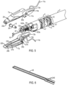
- FIG. 5 is a similar view as FIG. 4 with an exploded view of the jaws of the end effector and a partially transparent and cut-away view of a clevis of the end effector 3. The tendons that operate the wrist are not shown in the view of FIGS. 4 and 5 .
- the wrist 4 includes several wrist links 12.
- the links 12 are arranged in a pitch-yaw-yaw-pitch configuration (identified respectively with the labels "P" and "Y” in FIG. 3 ), which provides two-DOF articulation of the wrist 4.
- a pitch-yaw-yaw-pitch configuration identified respectively with the labels "P" and "Y” in FIG. 3
- Such a configuration is nonlimiting and exemplary, however, and other combinations of links may be provided to provide a variety of pitch and/or yaw articulation along the wrist as desired. More information about the principles of wrist 4's general configuration can be found, for example, in U.S. Patent No.
- Wrist actuation tendons that include cables 45, are routed through small holes 46 disposed at an outer peripheral region of the wrist links 12 to provide wrist movement. Constant tension on the tendons, including cables 45 and hypotubes 245, keeps the links 12 together and the end effector 3 properly positioned at the distal end of shaft 2.
- the tendons 45 are operated under a maximum working load ranging from about 5 lbs. to about 25 lbs., for example, about 16.8 lbs., and are able to withstand a load of about 1.5 times to about 3 times the working load.
- the tendons are U-shaped and loop back at the respective links 12 of the wrist 4, it should be appreciated that the cables could be provided as single cables that terminate at their ends at the links 12 without looping back. In such a configuration, for example, the overall number of cables and hypotubes may be reduced. In some cases, in such a cable configuration it may be desirable to increase the strength of the cables from that which can be used for the U-shaped cable configuration.
- Those having ordinary skill in the art are familiar with various tendon configurations to operate articulating linked wrist mechanisms in minimally invasive robotic surgical instruments.
- the wrist 4 may have an outer diameter ranging from about 5 mm to about 12 mm, for example, from about 5 mm to about 8.5 mm, and an overall length L w ranging from about 3/8 in. to about 2/3 in.
- the range of motion of the wrist 4 in either pitch or yaw is +/- 90 degrees and in roll is up to about +/- 260°, for example, +/- 180 degrees.
- the overall size e.g., lateral and longitudinal dimensions
- the exemplary embodiments of the present teachings are able to achieve these various motions of the end effector while the wrist is articulated and rolled, for example, through the range of motion described above.
- the pitch and yaw inputs may be received by the transmission mechanism 1 via teleoperated servo actuators associated with a patient side console (e.g., patient side console 1000) of a robotic surgical system.
- the transmission mechanism 1 may be configured like the exemplary embodiment of transmission mechanism 141 and receive pitch inputs via one input drive disk 40 and yaw inputs via another input drive disk 40, shown in FIG. 14B , and to receive an input via another drive disk 40 to rotate input shafts (one input shaft 60 being shown in FIG. 1B and the other hidden from view) within the transmission mechanism 141.
- the inputs and rotation of the input shafts 60 may be transmitted, for example to increase or decrease tension in the tendons 45/245 and/or to roll the shaft 2.
- transmission mechanisms that may be used to control tension in tendons to articulate jointed link wrist structures, reference is made to U.S. Patent No. US 6,817,974 B2, entitled “SURGICAL TOOL HAVING POSITIVELY POSITIONABLE TENDON-ACTUATED MULTI-DISK WRIST JOINT," issued Nov. 16, 2004 , which is incorporated by reference herein in its entirety.
- clevis 6 attaches the end effector 3 to the wrist 4 and supports opposing upper and lower jaws 7a,7b of the end effector 3.
- Jaws 7a,7b pivot around a clevis pin 8 to move the jaws 7a, 7b between the open and closed positions. That is, jaw 7a pivots about clevis pin 8 upwardly in the orientation of the surgical instrument in the figures, and jaw 7b pivots about pin 8 downwardly.
- FIG. 16 showing end effector jaws 1607a, 1607b pivoted to an open position).
- the clevis pin 8 extends through holes in clevis ears 9a, 9b and through holes 17a, 17b provided in cam extensions 13a, 13b respectively associated with each of the jaws 7a, 7b.
- the clevis ears 9a, 9b each include a slot 10a, 10b (depicted in FIGS. 3 and 5 ).
- the slots 10a,10b each receive an oppositely extending protrusion 163a, 163b of a drive nut 16, as described in more detail below.
- Each cam extension 13a, 13b includes an angled cam slot 14a,14b disposed proximal of each hole 17a, 17b, also for receiving the respective oppositely extending protrusions 163a, 163b of the drive nut 16.
- FIG. 7A shows a perspective view of an exemplary embodiment of a grip drive nut 16 in isolation
- FIG. 7B shows a cross-sectional view of the grip drive nut 16 taken from the perspective 7B-7B in FIG. 7A
- grip drive nut 16 includes a metal core 161 with an overmolded plastic casing 162.
- the overmolded plastic casing 162 extends within the throughhole 164 of the grip drive nut 16 and is formed with threading that engages with the threading on the lead screw 15 to reduce friction.
- the overmolded plastic casing 162 provides overall structural strength to the grip drive nut 16, including to the threading. Also, the overmolded plastic threading assists in increasing nut position precision as lead screw 15 turns. Further, the plastic casing 162 is disposed on the top, bottom, front, and back faces of the nut 16 (in the orientations of FIGS. 3-5 and 7 ), and extends along the edges of the side faces of the nut 16 surrounding the metal core. The plastic casing 162 helps to reduce friction, and thereby promote position precision, as the nut's 16 surfaces contact the clevis 6 and the cam extensions 13a, 13b during its movement along the lead screw 15. Drive nut 16 also includes two engagement pins 163a, 163b at opposite sides of the nut 16. Each pin 163a, 163b extends through an associated cam slot 14a, 14b and associated slot 10a, 10b in the clevis 6.
- the threading in the throughhole 164 of the grip drive nut 16 is a multi-start threading, and has a lead of about 0.1 in. per rotation. Providing a multi-start threading can facilitate manufacturability of the nut and the lead screw, improve strength, and/or facilitate movement of the nut in two directions along the lead screw.
- the core 161 of the nut 16 can comprise stainless steel, for example, a stainless steel alloy, such as, for example, 17-4 stainless steel.
- the overmolded plastic portion 162 can comprise a relatively high strength, low friction plastic capable of being applied to adhere to the metal core.
- the lead screw 15 is located distally against clevis pin 8 to maintain its position relative to the shaft 2 and connects at its proximal end to the torque drive component 18.
- the connection to the torque drive component 18 may, for example, be accomplished via a buttweld of the proximal end of the lead screw 15 to the distal end of the torque drive component 18, but such connection is non-limiting and exemplary only.
- a distal, nonthreaded end of the lead screw 15 can be received in a counterbore hole provided in clevis pin 8 disposed substantially opposite to a notch 28 in the clevis pin 8 that receives the cutting blade 19 of the cutting element. Accordingly, as shown in FIGS.
- the lead screw 15 is positioned distal to the wrist 4, substantially within the clevis 6.
- the clevis pin 8 acts as a distal stop that prevents movement of the lead screw 15 in the distal direction beyond the clevis pin 8.
- a proximal stop such as for example, a thrust ball bearing (not shown) provided in the transmission mechanism 1 can prevent the lead screw 15 from moving too far in a proximal direction.
- the thrust ball bearing may be disposed in the chassis of the motor assembly including the rack and pinion 50 shown in the exemplary embodiment of FIG.
- drive nut 16 travels along lead screw 15. Movement of the drive nut 16 along the lead screw 15 in turn moves the pins 163a, 163b along the associated cam slots 14a, 14b to open and close the jaws 7a, 7b. That is, as drive nut 16 travels in the distal direction, jaws 7a, 7b pivot about the clevis pin 8 to move the jaws 7a, 7b to the open position. As the drive nut 16 travels in the proximal direction, jaws 7a, 7b pivot about the clevis pin 8 to move the jaws 7a, 7b to the closed position.
- the location of the pins 163a, 163b at the distal end of the cam slots 14a, 14b defines the fully open position of the jaws 7a, 7b.
- the location of the pins 163a, 163b proximally in the cam slots 14a, 14b i.e., approximately in the position shown in FIG. 3 , somewhat distal to the proximal ends of the cam slots 14a, 14b) defines the fully closed position of the jaws 7a, 7b.
- the lead screw 15 may ultimately be coupled, e.g., through its drive mechanism, to a torque-limiting spring that acts as the mechanism by which the fully closed position of the jaws 7a, 7b is defined, as described, for example, in U.S. Provisional Patent Application No. US 61/491,804 (filed May 31, 2011 )," incorporated by reference in its entirety herein.
- the lead screw and nut combined with the pivoting cam slots 14a, 14b enables a strong grip force to be achieved by the jaws 7a, 7b, even within compact space restraints and various, relatively large range of DOF movements of the instrument.
- the cam slots 14a, 14b can provide a clamped mechanical advantage of about 4:1 in converting the linear motion of the nut 16 to the gripping motion of the jaws 7a, 7b.
- Persons of ordinary skill in the art will understand that various other jaw activation mechanisms are available, and in other embodiments only a single moving jaw may be used, with the other, opposing jaw being fixed in position.
- each of the pins 163a,163b through its associated clevis ear slot 10a,10b helps prevent the drive nut 16 from twisting within the clevis 6 to provide enhanced stability of the motion of the nut and thus opening and closing of the jaws 7a,7b.
- a torque drive component 18 that connects to and is driven by drive shaft 218 is used in accordance with various exemplary embodiments.
- a torque drive component 18 that may be used includes a multi-layered, tubular cable structure.
- the layered structure may have adjacent layers that comprise windings of differing directions, as explained in further detail with reference to the exemplary embodiment depicted in FIGS. 8A and 8B .
- FIGS. 8A and 8B include three layers of windings, the present disclosure is not limited to three layers. Rather, torque drive components in accordance with various exemplary embodiments can include two or more layers of windings, for example, with each layer having helical turns in differing directions.
- the first direction of twist is oriented to provide compression of the inner winding 181 and the outer windings 183 against themselves in the direction that moves the lead screw 15 so as to move the jaws 7a, 7b to the closed position. Accordingly, as can be seen in FIGS. 4 and 5 , the helical pattern of the threading on the lead screw 15 and the outer winding 183 are in the opposite direction.
- the outer winding 183 has a helical pattern of windings that rise from right to left in the clockwise direction and the threading on the lead screw 15 rises from left to right in the clockwise direction.
- the torque T close shown in FIG.
- torque drive component 18 is a hollowed cable structure, it flexes substantially equally in all directions, including pitch and yaw, and combinations thereof, with low friction.
- torque drive component 18 provides a relatively low bending force with a relatively high torque transmission capability to achieve transmission of a torque through wrist 4 sufficient to turn lead screw 15 without significantly limiting wrist 4's articulation and roll DOFs. With regard to the latter, flexibility in all directions facilitates maintaining concentricity of the various elements during roll DOF.
- a spring for example, provided in the transmission mechanism 1, may be used to assist in closing the jaws 7a, 7b, particularly to help close the jaws 7a, 7b when it is desirable to back the surgical instrument 100 through a cannula away from the surgical site.
- a spring-actuated mechanism can help to prevent damage to the end effector 3 if the jaws 7a, 7b are not placed in the closed position prior to retracting the instrument through a cannula.
- each jaw 7a,7b can include a metal core part 90b which includes the cam extension 13b, an electrode support part 91b, and an outer cover part 92b.
- the electrode support part 91b and outer cover part 92b can comprise a plastic material.
- the electrode support part 91b insulates the electrode 21b from the metal core.
- the outer cover part 92b receives and supports the combined metal core part 90b and electrode support part 91b.
- the metal core part 90b can provide strength to the jaws 7a, 7b to enable the jaws 7a, 7b to withstand the forces associated with gripping, for example, with minimal deflection.
- the metal core part 90b can comprise stainless steel or a stainless steel alloy, such as, for example, 17-4 stainless steel.
- the electrode support part 91b and the outer cover part 92b can be made by overmolding plastic around the metal core part 90b, such as, for example, a glass-filled polyphthalamide (PPA), for example, a 10- to 30-percent glass filled PPA.
- PPA glass-filled polyphthalamide
- the jaws 7a, 7b can be formed using a multi-shot molding process.
- the electrode support part 91b can be formed in a first shot of a mold and the outer cover part 92b in a second shot of the mold.
- the metal core part 90b can be obtained by metal injection molding (MIM).
- MIM metal injection molding
- the metal core part 90b can be machined.
- the electrode 21b can be positioned over the electrode support part 91b, and secured thereto during the second shot molding step.
- jaw 7a can be formed in the same manner as jaw 7b.
- the voltage of the energy source may be about 220 V p at a frequency ranging from about 100 Hz to about 400 Hz, and the power may be about 240 W to about 360 W, and the temperature of the electrodes 21a, 21b can be about 100 °C.
- the electrodes 21a, 21b may be stainless steel and control algorithms for conducting the electrical energy through the electrical conductors 11a, 11b can be implemented via a teleoperated robotic surgical system, for example, using the central control console 3000, as depicted in the exemplary embodiment of FIGS. 12A and 12B .
- bipolar energy source algorithms such as, for example, those available in electrosurgical generator products from ErbeElektrotechnik, GmbH, Germany, can be implemented (e.g., via generator 3090 in FIG. 12B ) to prevent tissue sticking to the electrodes 21a, 21b.
- the electrical conductors 11a, 11b can be any suitable conductive wire protected with an insulation layer surrounding the wire.
- the electrical conductors 11a, 11b can include a copper alloy wire with an ethylene tetrafluoroethylene (ETFE) insulation layer.
- ETFE ethylene tetrafluoroethylene
- each of the electrodes 21a, 21b in various exemplary embodiments may range, for example, from about 16 mm to about 18 mm, which may be desirable for sealing a vessel having a diameter of about 7 mm.
- the width of the electrodes 21a, 21b, as well as the corresponding jaws 7a, 7b, can present a generally tapered shape, having a larger width at the proximal end and a narrower width at the distal end.
- Such a tapered shape can be beneficial for dissection of tissue, including dissection of vessels.
- the tapered shape can improve visibility during dissection and can provide a smaller contact area to pierce tissue.
- the width at the proximal end, W e,p ranges from about 2.5 mm to about 5.5 mm, for example, the width may be about 5 mm; and the width, W e,d , at the distal end ranges from about 2.5 mm to about 3.5 mm, for example the width may be about 3 mm.
- the width of the electrodes 21a, 21b can be selected to provide fusing of both sides of dissected tissue (e.g., dissected ends of a vessel) gripped between the jaws 7a, 7b.
- the width may be selected to provide at least about a 1 mm seal on either side of the dissected tissue.
- each electrode 21a, 21b in various exemplary embodiments may range from about 0.005 in. to about 0.015 in., for example, the thickness may be about .010 in.
- the surfaces of the electrodes can be finished with a micro-inch surface finish, for example, an 8 micro-inch surface finish.
- each of the electrodes 21a, 21b is provided with a groove 23b (corresponding groove on electrode 21a is hidden from view in FIGS. 3-5 ) configured to receive and provide a track for the cutting element as it translates in the proximal and distal directions relative to the jaws 7a, 7b, as will be described in further detail below.
- the electrodes 21a, 21b are maintained spaced apart from each other to provide a gap g (see FIG. 3 ) by spacer lips 22a, 22b disposed at the distal end of each jaw 7a, 7b, and by spacer bars 26a, 26b at a proximal end of the electrodes 21a, 21b.
- the height of the spacer bars 26a, 26b above the surface of the electrodes 21a, 21b may be slightly lower than the height of the spacer lips 22a, 22b above the electrode surfaces to promote a uniform gap g across the length of the electrode surfaces while also permitting the electrode surfaces come sufficiently close along their entire length to ensure effective gripping and sealing of tissue.
- spacer structures can be placed in locations along the length of the electrode surfaces to maintain a gap between the electrode surfaces when the jaws 7a, 7b are in a closed position.
- jaws 1607a, 1607b can include spacer structures 1627a, 1627b on the upper surfaces of the electrodes 1621a, 1621b, located, for example, in a central portion along a length of the electrodes 1621a, 1621b.
- the spacer structures 1627a, 1627b can be formed by providing throughholes in one or both electrodes 1621a, 1621b, and then mold material underlying the respective electrodes 1621a, 1621b can be permitted to flow through the throughholes and beyond the electrode surfaces.
- the mold material that rises above the electrode surfaces can form the spacer structures 1627a, 1627b.
- the spacer structures and the underlying electrode support part e.g., like electrode support part 92b in FIG. 9
- Providing spacer structures in this manner may permit relatively small spacers to be placed along the length of the electrode using a relatively simple fabrication process.
- FIG. 16 illustrates two spacer structures on both electrodes 1621a, 1621b, any number of such spacer structures can be provided on one or both electrodes 1621a, 1621b, as desired.
- the gap g (shown in FIG. 3 ) between the electrodes 21a, 21b when the jaws 7a, 7b are in the closed position is on the order of a few thousandths of an inch, for example, about 0.004 inches.
- a small recess 24a, 24b extending substantially across the width of each jaw 7a, 7b can be placed distally of the associated electrode 21a, 21b, i.e., between the electrodes 21a, 21b and the spacer lips 22a, 22b.
- the recesses 24a, 24b can accommodate tissue gripped between the jaws 7a, 7b to assist in preventing gripped tissue from sliding out of the grip of the jaws 7a, 7b through the distal end of the end effector 3.
- the spacer lips 22a, 22b also can assist in preventing tissue from sliding through the distal end of the end effector 3.
- the recesses 24a, 24b can have a depth ranging from about 0.1 mm to about 0.4 mm.
- the electrical conductors 11a, 11b are recessed in the end effector 3 and are routed proximally back through the side channels 47 (shown in FIGS. 3 and 5 ) in the wrist 4 and then through the shaft 2, as described above with reference to FIGS. 2A and 2B .
- the electrical conductors 11a, 11b ultimately connect to a power generator source that may, for example, be located at the central control console 3000 of a teleoperated robotic surgical system depicted in FIGS. 12A and 12B .
- a separate one or more separate controllers 3080/3090 added to a central control console 3000 may have a power connection to supply power to the electrical conductors 11a, 11b; alternatively, the power source may be integrated with the central control console 3000.
- the electrical conductors 11a, 11b can be provided with slack when they are positioned against the jaws 7a, 7b, as illustrated in the exemplary embodiment of FIG. 5 .
- the opposing garage features 27b help to protect tissue from entering into the proximal end of the jaws 7a, 7b and potentially contacting the cutting blade 19.
- the distal end of the cutting blade 19 is positioned at a distal end of the grooves 23a, 23b respectively provided on the opposing electrode surfaces 21a, 21b of the jaws 7a, 7b. Since the cutting element drive component 20 is generally flexible, as will be described, the grooves 23a, 23b keep the cutting blade 19 aligned as it travels along the jaws 7a, 7b.
- the position of the cutting blade 19 relative to the bottom jaw 7b when the cutting blade 19 is in the distal-most position is shown. Accordingly, throughout its translation, the cutting blade 19 stays within the end effector 3; additionally, in its garaged position shown in FIG. 4 , the cutting blade 19 is retracted behind the electrode surfaces 21a, 21b substantially within the clevis pin 8 and garage features (27b described above and corresponding element associated with jaw 7a) of the end effector 3. Moreover, to enhance safety of operation of the surgical instrument 100, operation (i.e., translation) of the cutting element 19 from the garaged position can be prevented from occurring unless the jaws 7a, 7b are in the closed position.
- this can occur via a controller and software that controls the operation to drive the cutting element drive component 20, as taught for example in U.S. Provisional Patent Application No. US 61/491,647, entitled “POSITIVE CONTROL OF ROBOTIC SURGICAL INSTRUMENT END EFFECTOR,” (filed May 31, 2011 ), incorporated by reference in its entirety herein.
- a robotic surgical system e.g., which can include use of an onboard motor like motor 5 in FIG. 14A .
- a software feature prevents actuation of the cutting blade 19, for example via control of motor 5, until the jaws 7a,7b are sufficiently closed to allow cutting blade 19 to extend safely within slots 23a, 23b, without risk of the cutting element coming out of the slots 23a, 23b and potentially outside of the jaws 7a, 7b.
- the cutting element drive component 20 is a cable having a distal end that is welded to the proximal end of the cutting blade 19.
- the blade 19 and cable 20 may be blend welded together to provide a smooth interface between the two components. Providing a relatively smooth interface between the two components can reduce the risk of having the cutting element become stuck on tissue during a cutting procedure.
- the drive component 20 is attached at a proximal end to the transmission mechanism 1, which is configured to provide a linear (push/pull) motive force to the drive component 20 and allow roll DOF, and as described above, is routed centrally through the shaft 2 and wrist 4 to the end effector 3.
- the cable structure of the drive component 20 is sufficiently flexible so as to withstand bending in various directions about its longitudinal axis, while also providing sufficient compressive and tensile strength to withstand and transmit the push/pull actuation forces from the transmission mechanism 1 to translate the cutting blade 19, including through tissue in order to effect cutting.
- the central routing of the drive component 20 through the shaft and wrist 4 permits the surgical instrument 100 to have a relatively compact design while also providing centering of the cutting blade 19 relative to the end effector 3 during the cutting operation.
- central routing of the drive component 20 can reduce friction that acts on the drive component 20 as it moves through wrist 4, particularly when wrist 4 is articulated and/or rolled, when translating the cutting blade 19. In this way, the force required to drive the cutting blade 19 can be reduced in comparison with a configuration in which the drive component 20 is routed toward an outer periphery of the instrument 100 as opposed to centrally. Further, central routing of the cutting drive component 20 can result in substantially no change of length during articulation of the wrist 4, allowing the cutting blade 19 to remain in the garaged position during articulation.
- the drive component 20 can include a superelastic flexible wire having a high tensile and compressive strength, such as, for example, a nitinol wire.
- the cutting blade 19 also can be made of nitinol.
- the lead screw 15 and torque drive component 18 are both hollow, and cutting element drive component 20 is routed through the hollow centers of the lead screw 15 and the torque drive component 18.
- the resulting combined structure of the torque drive component 18 and the cutting element drive component 20 flexes equally in pitch, yaw, and combinations of pitch and yaw, with relatively low friction as the combined structure passes through wrist 4.
- the grip DOF and cutting element translation DOF can be transmitted through wrist 4 to end effector 3 in a compact configuration that allows the relatively small wrist 4 to operate in Cartesian pitch, yaw, and roll DOFs.
- a minimally invasive surgical instrument has an end effector with integrated tissue fusing and cutting functions and a wrist mechanism that allows the end effector to be oriented in Cartesian pitch, yaw, and roll (roll is enabled by changing wrist 4 pitch and yaw as necessary as shaft 2 rolls).
- the cutting blade 19 has a concave "V" shape cutting surface 190, which can assist in pulling tissue into the cutting surface.
- V concave
- the blade may have a straight, angled, or curved cutting surface.
- the proximal end of the cutting blade 19 may have rounded top corners to minimize the risk of the cutting blade 19 getting stuck when back-driven after completion of a cutting procedure.
- the blade 19 is made of stainless steel (e.g., 716 stainless steel) and has a double grind cutting surface. The blade 19 can be secured to the drive component 20 by various mechanisms, including, for example, welding.
- the blade 19 has a height, H B , ranging from about 0.08 in. to about 0.15 in., for example about .10 in., and a length, L B , ranging from about 0.10 in. to about 0.13 in., for example, about 0.115 in.
- the cutting mechanism drive component 20 can be actuated via an onboard motor disposed in the transmission mechanism 1, for example, via an onboard motor 5 in conjunction with a worm gear and rack and pinion mechanism 50 as illustrated in the exemplary embodiment of transmission mechanism 141 shown in FIG. 14A .
- an onboard motor disposed in the transmission mechanism 1 for example, via an onboard motor 5 in conjunction with a worm gear and rack and pinion mechanism 50 as illustrated in the exemplary embodiment of transmission mechanism 141 shown in FIG. 14A .
- one or more limit switches 55 can be used to sense the position of the cutting blade 19.
- the instrument 100 can be provided with a feature that permits the cutting element 19 to be manually retracted, such as, for example, via a hex wrench or other tool configured to engage through the chassis of the transmission mechanism, for example, with a worm gear used to drive the cutting element drive component.
- the outer diameter of shaft 2, end effector 3 (in a closed position), and wrist 4 ranges from about 5 mm to about 12 mm, for example from about 5 mm to about 8.5 mm, for example, the outer diameter may be about 8.5 mm in one exemplary embodiment. Consequently, tissue fusing and cutting surgical instruments in accordance with various exemplary embodiments can be inserted through a patient's body wall by using a cannula capable of inserting other 5 mm or 8.5 mm class telerobotic surgical instruments. In the case of such 5 mm or 8.5 mm outer diameter cutting and fusing surgical instrument, the outer diameter is about thirty-eight percent smaller than the outer diameter of a 13 mm wristed stapling surgical instrument. Moreover, in the case of performing cutting and fusing surgical procedures, smaller diameters have advantages for visualization and access in such procedures that may be more delicate and/or difficult to perform, and generally within smaller spaces.
- the surgical instrument 100 may be configured as a single-use, disposable surgical instrument. Accordingly, to reduce costs associated with manufacturing the surgical instrument yet provide an instrument sufficiently strong to perform the various operations required, various components are made of plastic and are formed using an injection molding process. In addition, where additional strength for a component is desirable, various components or parts thereof may be made using a metal injection molding (MIM) process.
- MIM metal injection molding
- various gears, gimbal plates, pulleys, links, etc. may be made of plastic, machined metal, stamped sheet metal, powdered metal, and/or MTM parts.
- such a motor can be a relatively inexpensive motor, such as, for example, a DC motor configured to deliver sufficient force when operating with voltage inputs ranging from about 5 V to about 15 V, for example, about 5.5 V to about 10 V.
- the surgical instrument 100 can be inserted (e.g., laparoscopically or thorascopically) into the body of a patient, for example, through a cannula, and advanced to a position generally in the proximity of a work site at which a cutting and fusing procedure is desired.
- the transmission mechanism 1, 141 can receive one or more inputs (e.g., at input disks 40 in the exemplary embodiment of transmission mechanism 141) to roll and/or articulate the wrist 4, such as, for example, via roll, pitch, yaw, or a combination of any of those motions.
- the transmission mechanism 1 can transmit the inputs into various forces and/or torques to ultimately actuate (drive) the overall instrument shaft 2 (for example via roll) and/or to modify the tension in tendons 45 to articulate the wrist 4 in pitch and/or yaw.
- the transmission mechanism 1 (e.g., at input disks 40 in the exemplary embodiment of transmission mechanism 141) can receive an input to open the jaws 7a, 7b of the end effector 3 and the instrument 100 can be advanced such that tissue for which fusing/cutting is desired is positioned between the opened jaws 7a, 7b.
- the transmission mechanism 1 can transmit the input to open the jaws 7a, 7b by exerting a torque in a first direction on the hollow drive shaft 218 and torque drive component 18, which torque can be transmitted to rotate lead screw 15 and to move the drive nut 16 along the lead screw 15 toward a distal end of the end effector 3.
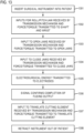
- the transmission mechanism 1 (e.g., at input disks 40 in the exemplary embodiment of transmission mechanism 141) can receive, as shown at 1304 in FIG. 13 , an input to close the jaws 7a, 7b in order to grip the tissue.
- the transmission mechanism 1 can transmit the input to close the jaws 7a, 7b by exerting a torque in a second direction, opposite to the first direction, on the hollow drive shaft 218 and torque drive component 18, which torque can be transmitted to rotate lead screw 15 and to move the drive nut 16 along the lead screw 15 toward a proximal end of the end effector 3.
- electrosurgical energy e.g., bipolar energy
- electrosurgical energy can be passed through the electrical conductors 11a, 11b to activate the electrodes 21a, 21b.
- the bipolar energy transmitted to the electrodes 21a, 21b is sufficient for the electrodes 21a, 21b to fuse the tissue gripped between them.
- a signal such as for example, an audible signal (e.g., a beep or otherwise) and/or a visible signal observable for example on a monitor or other display, can be provided to the instrument operator to confirm that the tissue fusing has been completed.
- an input can be provided to the transmission mechanism 1 to drive the cutting element.
- the transmission mechanism 1 can transmit various forces and torques to ultimately drive the cutting element drive component 20, for example, using push/pull forces on the same.
- the cutting element drive component 20 can be actuated to drive the cutting element from the garaged position, to the distal most position, and back to the garaged position using a single input to the transmission mechanism 1. Accordingly, the entire cutting translation motion (i.e., from the garaged position to the distal most position and back) can be automatically completed.
- a robotic surgical system such as that depicted in FIGS.
- the cutting operation may be prevented from occurring, e.g., through the use of appropriate algorithms and feedback sensors controlled by a controller such as integrated with or located as a separate unit of a central control console 3000, if the jaws 7a, 7b are not in the closed position.
- a controller such as integrated with or located as a separate unit of a central control console 3000, if the jaws 7a, 7b are not in the closed position.
- the instrument 100 can be retracted from the patient at 1308 shown in FIG. 13 , for example, via a cannula.
- the surgical instrument can be operated as a hand-held device with various inputs to the transmission mechanism being provided manually
- the instrument 100 can be interfaced with a robotic surgical system, such as that shown in FIGS. 12A and 12B and as described above.
- the transmission mechanism may be configured as transmission mechanism 141 in FIGS. 14A and 14B , and the various described inputs can be received at the input disks 40 with the instrument disposed at a patient side console 1000 controlled via a central control console 3000 from signals received from a surgeon side console 2000.
- a voltage signal can be output from a controller, such as a separate instrument control box 3080 mounted or otherwise connected to a central control console 3000 or from a controller integrated therewith, and received via an onboard motor 5 disposed in the transmission mechanism 141.
- a controller such as a separate instrument control box 3080 mounted or otherwise connected to a central control console 3000 or from a controller integrated therewith, and received via an onboard motor 5 disposed in the transmission mechanism 141.
- inputs from the surgeon side console 2000 or from input units otherwise accessible to a surgeon can be provided to the controller(s) via various pedals 2010/2090 (e.g., to control cutting and fusing), and via hand-held grasping mechanisms 2020 (e.g., to control movement of the wrist 4 and instrument shaft 2).
- pedals 2010/2090 e.g., to control cutting and fusing
- hand-held grasping mechanisms 2020 e.g., to control movement of the wrist 4 and instrument shaft 2.
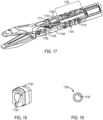
- FIG. 17 depicts a partially cutaway, perspective view of the wrist, end effector and a portion of the shaft an exemplary embodiment of a fusing and cutting surgical instrument in accordance with the present disclosure, with various components having differing structural configurations from other exemplary embodiments described above, as will be further explained below.
- the electrical conductors (one such electrical conductor 1711 being depicted), instead of having the slacked configuration as shown in FIG. 5 for example, are routed in a substantially straight configuration manner from the electrodes of the end effector.
- the electrical conductors 17 can be routed in a substantially straight configuration through a molded plug 1720 (shown in isolation in FIG.
- the cable routing plug 1720 in an exemplary embodiment can be made of a molded plastic or rubber material that can route and hold the conductor cables 1711 in a tensioned manner through routing holes 1722. In this way, interference of the conductor cables 1711 with the movement of the surgical instrument, particularly the end effector movement, can be minimized.
- the cable routing plug 1720 can be made of a material selected to increase friction between the conductor cables 1711 and the plug 1720 to the extent some movement of the cables 1711 through the routing holes 1722 occurs as a result of movement of the end effector.
- Exemplary materials that may be used for the plug 1720 include, but are not limited to, silicone, thermoplastic elastomers, and rubbers.
- the electrical conductors 1711 can be routed through the holes 47 as they pass through the wrist 4, as shown in FIGS. 3 and 5 .
- the exemplary embodiment of FIG. 17 also illustrates a torque drive component with a portion of the outer surface of the outer winding layer removed, for example, via grinding (e.g., centerless grinding). As illustrated in the exemplary embodiment of FIG. 17 , a portion 1750 that extends substantially along the wrist 1704 of the torque drive component 1718. Such removal of a portion of the outer surface of the outer layer of the torque drive component can provide a smoother outer surface, which in turn can result in increased flexibility of the torque drive component, enhance the consistency of the grip force, and/or increase the clearance between the torque drive component 1718 and the wrist 1704.
- the outer layer of the torque drive component can be ground to about half of the thickness of the winding.
- the outer winding layer may be ground to an outer diameter of the multi-layered tubular structure ranging from about 0.068 inches to about 0.070 inches.
- a relief surface profile 1780 (the other relieve surface profile on the opposite side not visible in FIG. 17 ) can be provided on the surfaces of the cam extensions that abut the clevis ears 1709. Such a relief surface profile can provide a clearance between the two surfaces in order to reduce friction during the opening and closing of the jaws.
- Another surface that may include a surface profile in relief is the interior surface of the channel in the clevis through which the torque drive component passes.
- the channel 1790 through which the torque drive component 1718 passes in the clevis 1706 can be provided with a relief interior surface profile 1795 to assist in reducing friction between the torque drive component 1718 and the channel 1790.
Landscapes
- Health & Medical Sciences (AREA)
- Surgery (AREA)
- Life Sciences & Earth Sciences (AREA)
- Engineering & Computer Science (AREA)
- Biomedical Technology (AREA)
- Public Health (AREA)
- Nuclear Medicine, Radiotherapy & Molecular Imaging (AREA)
- Veterinary Medicine (AREA)
- General Health & Medical Sciences (AREA)
- Heart & Thoracic Surgery (AREA)
- Medical Informatics (AREA)
- Molecular Biology (AREA)
- Animal Behavior & Ethology (AREA)
- Robotics (AREA)
- Physics & Mathematics (AREA)
- Otolaryngology (AREA)
- Plasma & Fusion (AREA)
- Surgical Instruments (AREA)
- Manipulator (AREA)
Abstract
Description
- This application claims priority to
U.S. Provisional Patent Application No. 61/444,400, filed on February 18, 2011 U.S. Provisional Patent Application No. 61/491,719, filed May 31, 2011 - Aspects of the present disclosure relate to surgical instruments that are minimally invasive and integrate into a single device the use of energy to fuse tissue and a component that cuts the fused tissue. More particularly, aspects of the present disclosure relate to such devices that have an articulating wrist mechanism that supports a surgical instrument end effector configured to cut and fuse tissue.
- The use of energy, such as, for example bipolar energy, to fuse tissue is known. Briefly, two or more tissues (e.g., a tissue bundle) are gripped between two electrodes, and electrosurgical energy is passed between the electrodes in order to fuse the tissues together. An example of such tissues includes the opposing walls of a blood vessel. In this way, the blood vessel can be fused closed, resulting in a sealing of the vessel at the fused region. Surgical instruments that perform this action are often referred to as sealing instruments (e.g., a "vessel sealer"). Such surgical instruments also can be used, for example, for cold cutting, tissue dissection, coagulation of tissue bundles generally (e.g., other than for sealing), and tissue manipulation/retraction.
- Once tissues, such as, for example, of a blood vessel, are fused together, the fused region can be safely cut without any resulting bleeding. For both convenience and cutting accuracy, surgical instruments have been developed that utilize an end effector that integrates the use of tissue fusing and cutting.
- The benefits of minimally invasive (e.g., laparoscopic, thoracoscopic, etc.) surgery are known. Instruments for such surgery typically have a surgical end effector mounted at the distal end of a long shaft that is inserted through an opening (e.g., body wall incision, natural orifice) to reach a surgical site. In some cases, the surgical instruments can be passed through a cannula and an endoscope can be used to provide images of the surgical site. In some cases, an articulating wrist mechanism may be mounted at the instrument's distal end to support the end effector and change its orientation with reference to the shaft's longitudinal axis. It can be appreciated that minimizing the outer diameter of the shaft, wrist, and end effector may be desirable to reduce patient trauma during minimally invasive surgery.
- A disadvantage of existing minimally invasive surgical instruments that offer an integrated tissue fusing and cutting end effector is that the articulating wrist mechanism allows the end effector to articulate relative to the shaft with only a single degree of freedom (DOF) (e.g., arbitrarily defined orthogonal "pitch" or "yaw" orientations with reference to the shaft), although other DOF movements may be considered to exist, such as, for example, roll, grip, translation (e.g., movement of cutting knife along the jaws), etc.. This single articulation DOF limitation is due to the configuration of the cutting knife, which is typically an elongated, substantially planar metal band or ribbon structure having a distal end provided with sharp cutting edges. Such a planar structure can flex back and forth about the plane in which the structure lies, but not in the orthogonal plane (i.e., in the plane of the structure). Since the planar cutting knife structure passes through the wrist mechanism in order to drive the cutting knife, the wrist mechanism is limited to a configuration in which only a single articulation DOF motion can occur, namely about the plane of the planar cutting knife; the wrist mechanism is not configured to articulate within the plane of the planar cutting knife structure. Cutting knives with planar band or ribbon structures can also impact the roll DOF of a surgical instrument, requiring various coupling structures to maintain substantially concentric positioning between the various elements of the end effector during roll.
- Attaining sufficient gripping pressure on tissue, such as a vessel, for sealing can also be challenging in such instruments, particularly when combined with achieving various other DOF movements, such as, for example, roll DOF and articulation DOF. Also, attaining sufficient gripping pressure can pose challenges when attempting to reduce the size of the overall instrument.
- Another type of minimally invasive surgical instrument is a stapling instrument. Such stapling instruments securely staple tissues together with several staple rows, and these instruments also use an integrated cutting mechanism to drive a cutting knife between the staple rows. Minimally invasive stapling instruments with a tissue cutting feature have been developed with the integrated stapling and cutting end effector mounted on a two-DOF articulation wrist mechanism so that the end effector orientation can be changed in both "pitch" and "yaw". See e.g.,
U.S. Patent Application Nos. 12/945,461 (filed Nov. 12, 2010 12/945,730 (filed Nov. 12, 2010 12/945,740 (filed Nov. 12, 2010 12/945,748 (filed Nov. 12, 2010 US 2010/0292691 A1 (filed Jul. 22, 2010 ). In contrast, other minimally invasive surgical instruments, such as those used with the robotic surgical systems commercialized by Intuitive Surgical, Inc. of Sunnyvale, California, have an outer diameter of the wrist and/or end effector (e.g., in a closed position of jaws of the end effector) in the range of about 8 mm or about 5 mm. - Persons of ordinary skill in the art will appreciate that reducing the overall size of a surgical instrument while preserving desired functions, features, and capabilities is often not merely a case of scaling down known components. Preserving design requirements for even a small size reduction, such as reducing an instrument's outer diameter by about 2 mm to about 3 mm, can be a difficult task due to material properties, component fabrication limitations, introduction of friction between moving parts, limitations on strength of components as their sizes are reduced, overall design of such smaller mechanisms while maintaining high force requirements, and other impacts on operation. Thus, although highly desirable, a minimally invasive surgical instrument with an integrated tissue fusing and cutting feature, a two-DOF articulation wrist mechanism, and an outer diameter on the order of other commonly used minimally invasive surgical instruments has not been available. In addition, such a surgical instrument that can be interfaced with and controlled by a robotic surgical system is desirable.
- The present teachings may solve one or more of the above-mentioned problems and/or may demonstrate one or more of the above-mentioned desirable features. Other features and/or advantages may become apparent from the description that follows.
- In accordance with various exemplary embodiments, the present teachings contemplate a surgical instrument that comprises a shaft having a proximal end and a distal end, and a wrist coupled to the distal end of the shaft and configured to articulate in multiple degrees of freedom coupled to the distal end of the shaft. The surgical instrument can further comprise an end effector supported by the wrist, wherein the end effector includes a cutting element and jaws configured to grip tissue and to fuse tissue, for example, via electrosurgical energy. The surgical instrument can be configured for use with a teleoperated robotic surgical system that can include a patient side console configured to interface with and actuate the surgical instrument and a surgeon side console configured to receive inputs from a surgeon to control the actuation of the surgical instrument.
- In accordance with various exemplary embodiments, the present teachings contemplate a method of operating a surgical instrument which includes receiving at least one first input at a transmission mechanism disposed at a proximal portion of the surgical instrument to articulate a multiple degree-of-freedom articulable wrist of the surgical instrument in at least one of pitch and yaw, and transmitting one or more forces via the transmission mechanism to articulate the wrist in response to the first input. The method further includes receiving a second input at the transmission mechanism to open jaws of an end effector supported by the wrist, and transmitting torque via the transmission mechanism to a torque drive component to open the jaws. The method further includes receiving a third input at the transmission mechanism to close the jaws of the end effector, and transmitting torque via the transmission mechanism to the torque drive component to close the jaws to grip tissue between the jaws. Additionally, the method includes transmitting electrosurgical energy to the jaws to fuse the tissue, receiving a fourth input at the transmission mechanism to translate a cutting element of the end effector, and transmitting a force to a cutting element drive component via the transmission mechanism to translate the cutting element relative to the end effector.
- Additional objects and advantages of the present teachings will be set forth in part in the description which follows, and in part will be obvious from the description, or may be learned by practice of the present disclosure and/or claims. At least some of those objects and advantages of the invention will be realized and attained by means of the elements and combinations particularly pointed out in the appended claims.
- It is to be understood that both the foregoing general description and the following detailed description are exemplary and explanatory only and are not restrictive of the present disclosure and claims, which are entitled to their full breadth of scope including equivalents.
- The present disclosure can be understood from the following detailed description, either alone or together with the accompanying drawings. The drawings are included to provide a further understanding of the present disclosure, and are incorporated in and constitute a part of this specification. The drawings illustrate one or more exemplary embodiments of the present teachings and together with the description serve to explain certain principles and operation. In the drawings,
-
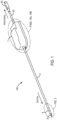
FIG. 1 is a diagrammatic perspective view of a minimally invasive surgical instrument in accordance with an exemplary embodiment of the present disclosure; -
FIG. 2A is a partial, longitudinal cross-sectional view of a shaft and wrist of the surgical instrument ofFIG. 1 in accordance with an exemplary embodiment; -
FIG. 2B is a transverse, cross-sectional view of the instrument shaft taken from theperspective 2B-2B inFIG. 2A ; -
FIG. 3 is a detailed perspective view of the end effector, wrist, and portion of the shaft of the surgical instrument ofFIG. 1 in accordance with an exemplary embodiment; -
FIG. 4 is a partially exploded, partially cut-away perspective view of the end effector, wrist, and portion of the shaft ofFIG. 1 in accordance with an exemplary embodiment; -
FIG. 5 is a partially exploded, partially transparent perspective view of the end effector, wrist, and portion of the shaft ofFIG. 1 in accordance with an exemplary embodiment; -
FIG. 6 is a partial perspective view of a wrist drive tendon in accordance with an exemplary embodiment; -
FIG. 7A is a perspective view of a grip drive nut in accordance with an exemplary embodiment; -
FIG. 7B is a cross-sectional view of the grip drive nut taken from theperspective 7B-7B inFIG. 7A ; -
FIG. 8A is a partial side view of an exemplary embodiment of a torque tube in accordance with an exemplary embodiment; -
FIG. 8B is a cross-sectional view of the torque tube from theperspective 8B-8B ofFIG. 8A ; -
FIG. 9 is an exploded view of a jaw assembly in accordance with an exemplary embodiment; -
FIG. 10 is an isolated, partial side view of a cutting element and cutting drive component in accordance with exemplary embodiments; -
FIG. 11 is a partial isolated, perspective view of the bottom jaw and cutting element of the end effector ofFIGS. 3-5 in accordance with an exemplary embodiment; -
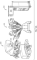
FIG. 12A is a diagrammatic perspective view of an exemplary robotic surgical system with which surgical instruments in accordance with various exemplary embodiments of the present disclosure can be used; -
FIG. 12B is a schematic view of an exemplary robotic surgical system with which surgical instruments in accordance with various exemplary embodiments of the present disclosure can be used; -
FIG. 13 is a flow diagram showing an exemplary method for operating a fusing and cutting surgical instrument in accordance with various exemplary embodiments of the present disclosure; -
FIGS. 14A-14B are detailed views of the corresponding labeled portions of the surgical instrument ofFIG. 1 in accordance with an exemplary embodiment; -
FIG. 15 is a cross-sectional view of an adapter structure and seals ofFIG. 2A in accordance with an exemplary embodiment; -
FIG. 16 is an isolated, perspective view of jaws with spacers, shown in an open position of the jaws, in accordance with an exemplary embodiment; -
FIG. 17 is a partially cut-away perspective view of the end effector, wrist, and portion of the shaft of a fusing and cutting surgical instrument in accordance with an exemplary embodiment; -
FIG. 18 is a perspective view of a cable routing plug in accordance with an exemplary embodiment; and -
FIG. 19 is a cross-sectional view of an exemplary embodiment of a channel in the clevis ofFIG. 17 . - This description and the accompanying drawings that illustrate exemplary embodiments should not be taken as limiting, with the claims defining the scope of the present disclosure. Various mechanical, compositional, structural, electrical, and operational changes may be made without departing from the scope of this description and the invention as claimed, including equivalents. In some instances, well-known structures, and techniques have not been shown or described in detail so as not to obscure the disclosure. Like numbers in two or more figures represent the same or similar elements. Furthermore, elements and their associated features that are described in detail with reference to one embodiment may, whenever practical, be included in other embodiments in which they are not specifically shown or described. For example, if an element is described in detail with reference to one embodiment and is not described with reference to a second embodiment, the element may nevertheless be claimed as included in the second embodiment.
- For the purposes of this specification and appended claims, unless otherwise indicated, all numbers expressing quantities, percentages, or proportions, and other numerical values used in the specification and claims, are to be understood as being modified in all instances by the term "about," to the extent they are not already so modified. Accordingly, unless indicated to the contrary, the numerical parameters set forth in the following specification and attached claims are approximations that may vary depending upon the desired properties sought to be obtained by the present invention. At the very least, and not as an attempt to limit the application of the doctrine of equivalents to the scope of the claims, each numerical parameter should at least be construed in light of the number of reported significant digits and by applying ordinary rounding techniques.
- Notwithstanding that the numerical ranges and parameters setting forth the broad scope of the invention are approximations, the numerical values set forth in the specific examples are reported as precisely as possible. Any numerical value, however, inherently contains certain errors necessarily resulting from the standard deviation found in their respective testing measurements. Moreover, all ranges disclosed herein are to be understood to encompass any and all subranges subsumed therein.
- It is noted that, as used in this specification and the appended claims, the singular forms "a," "an," and "the," and any singular use of any word, include plural referents unless expressly and unequivocally limited to one referent. As used herein, the term "include" and its grammatical variants are intended to be non-limiting, such that recitation of items in a list is not to the exclusion of other like items that can be substituted or added to the listed items.
- In accordance with various exemplary embodiments, the present disclosure contemplates a surgical instrument that includes a shaft, a wrist that is capable of articulating in both pitch and yaw directions and combinations thereof, and an end effector that includes components operable to perform gripping, fusing, and cutting procedures. The present disclosure contemplates such a surgical instrument that is able to provide both a sufficient gripping force (including pressure on the gripped tissue) desirable for achieving tissue (e.g., vessel) fusing and a sufficient cutting force, throughout a relatively wide range of articulation and roll DOF movements of the instrument. Further, in various exemplary embodiments, the present disclosure contemplates such a surgical instrument that is minimally invasive, and provides a compact design, having overall outer diameters of the shaft, wrist, and end effector that are relatively small in comparison with other minimally invasive surgical instruments that use articulation wrist structures in combination with multiple purpose end effectors, such as various stapling instruments for example.
- Various exemplary embodiments of the present disclosure thus provide an integrated tissue fusing and cutting end effector, the orientation of which can be independently controlled in Cartesian pitch, yaw, and roll DOFs. In addition, the cutting element can be independently controlled in translation DOF for movement relative to the end effector substantially along a longitudinal direction of the end effector jaws, even when the wrist is articulated in pitch and/or yaw relative to a longitudinal axis of the instrument shaft, and/or when the instrument shaft and end effector are rolled (i.e., rotated about the longitudinal axis of the shaft).
- With reference now to
FIG. 1 , a diagrammatic view of a minimally invasivesurgical instrument 100, and various components thereof shown in detail, in accordance with an exemplary embodiment of the present disclosure is depicted.FIG. 1 is a perspective view of the minimally invasivesurgical instrument 100, andFIGS. 14A-14B show the detailed views of an exemplary embodiment of the corresponding portion labeled inFIG. 1 . The directions "proximal" and "distal" are used herein to define the directions as shown inFIG. 1 , with distal generally being in a direction further along a kinematic arm or closest to the surgical work site in the intended operational use of theinstrument 100, for example, in use for performing surgical procedures. As shown inFIG. 1 , theinstrument 100 generally includes a force/torque drive transmission mechanism 1, aninstrument shaft 2 mounted to the transmission mechanism 1; an integrated gripping, fusing, and cutting end effector 3 disposed at the distal end of theinstrument 100; and anarticulation wrist 4 disposed at a distal end of theshaft 2 between theshaft 2 and the end effector 3. In various exemplary embodiments, the overall length of theinstrument 100 from the distal end of the end effector 3 to the proximal end of the transmission mechanism 1 ranges from about 21 inches to about 25 inches. - In an exemplary embodiment, the
instrument 100 is configured to be mounted on and used with a minimally invasive surgical robotic system, which in an exemplary embodiment includes apatient side console 1000, asurgeon side console 2000, and an clectronics/control console 3000, as illustrated in the diagrammatic perspective and schematic views ofFIGS. 12A and12B . It is noted that the system components inFIGS. 12A and12B are not shown in any particular positioning and can be arranged as desired, with the patient side console being disposed relative to the patient so as to effect surgery on the patient. A non-limiting, exemplary embodiment of a surgical robotic system with which theinstrument 100 can be utilized is a da Vinci® Si (model no. IS3000) commercialized by Intuitive Surgical, Inc. In general, thesurgeon side console 2000 receives inputs from a surgeon by various input devices, including but not limited to, gripping mechanisms 2004, foot pedals 2002, etc. The surgeon side console serves as a master controller by which thepatient side console 1000 acts as a slave to implement the desired motions of the surgical instrument, and accordingly perform the desired surgical procedure. Thesurgeon side console 2000 also can include a viewer ordisplay 2006 that allows the surgeon to view a three dimensional image of the surgical site. Thepatient side console 1000 can include a plurality of jointedarms 1002 configured to hold various tools, including, but not limited to, for example, a surgical instrument with an end effector (e.g., surgical instrument 100), and an endoscope. Based on the commands input at thesurgeon side console 2000, thepatient side console 1000 can interface with a transmission mechanism of the surgical instrument to position and actuate the instrument to perform a desired medical procedure. The electronics/control console 3000 receives and transmits various control signals to and from thepatient side console 1000 and thesurgeon side console 2000, and can transmit light and process images (e.g., from an endoscope at the patient side console 1000) for display, such as, e.g.,display 2006 at thesurgeon side console 2000 and/or on adisplay 3006 associated with the electronics/control console 3000. Those having ordinary skill in the art are generally familiar with such robotically controlled surgical systems. - In an exemplary embodiment, the electronics/
control console 3000 may have all control functions integrated in one or more controllers in theconsole 3000, or additional controllers (e.g., as shown at 3080 inFIG. 12B ) may be provided as separate units and supported (e.g., in shelves) on the electronics/control console 3000 for convenience. Such controllers may, in exemplary embodiments, be in direct electrical/control communication with asurgical instrument 100, as shown, e.g., by inFIG. 12B . The latter may be useful, for example, when retrofitting existing electronics/control consoles to control surgical instruments requiring additional functionality. The electronics/control console 3000 also can include aseparate controller 3090 for electrocautery energy in an exemplary embodiment, which can be delivered to the surgical instrument end effector. Likewise, although in various exemplary embodiments, one or more input mechanisms may be integrated into thesurgeon side console 2000, various other input mechanisms (e.g., as shown byelement 2090 inFIG. 12B ) may be added separately and provided so as to be accessible to the surgeon during use of the system, but not necessarily integrated into thesurgeon side console 2000. - The transmission mechanism 1 transmits received actuation inputs to resulting torques and forces to effect movement of the
instrument shaft 2,wrist 4, and end effector 3, and associated components, to accomplish various motions resulting in a multi-DOF surgical instrument. For example, the transmission mechanism 1 can be controlled via inputs (e.g., torque inputs) to rollshaft 2, and consequently end effector 3 (roll DOF); open and close jaws of the end effector 3 (grip or clamp DOF); articulate wrist 4 (articulation DOF); and translate a cutting element (not shown in the view ofFIG. 1 ) (translation DOF). In various exemplary embodiments, as will be described in further detail below, thewrist 4 can be configured for two-DOF articulation in orthogonal directions to provide both "pitch" and "yaw" movement of end effector 3 (yaw being arbitrarily defined as being the plane of motion of the end effector jaws, pitch being orthogonal to yaw). - As depicted in the exemplary embodiment of
FIG. 14B , which shows the underside of an exemplary embodiment of atransmission mechanism 141 that can be used as transmission mechanism 1 inFIG. 1 , thetransmission mechanism 141 can include one or moreinput drive disks 40 configured to interface with a patient-side control console, such asconsole 1000 inFIGS. 12A and12B , to receive input to drive the various motions of the instrument 1, as will be explained in more detail below. - As mentioned above, in an exemplary embodiment, for example as shown in
FIGS. 14A and 14B , the transmission mechanism 141 (shown inFIG. 14A with its protective cover removed to provide an internal view) can be configured to receive various inputs, including for example, torque inputs via teleoperated servo actuators of a robotic surgical system that interface with theinput disks 40, as persons with ordinary skilled in the art are familiar with. These torque inputs can be used to transmit roll to the instrument shaft (labeled 142 inFIGS. 14A and 14B ), to transmit a force to open and close the jaws of the end effector (FIG. 1 shows the jaws of end effector 3 in a closed position), and to transmit a force to articulate the wrist (wrist 4 inFIG. 1 ), for example, two-DOF articulation. In addition, in an exemplary embodiment, thetransmission mechanism 141 can include an onboardelectric motor 5 that receives input voltages, for example from a robotic surgical control system (e.g., via a controller that is either integrated intocentral control console 3000 or separate therefrom but associated therewith), to drive the cutting element (not shown inFIG. 1 ) via gears and a rack andpinion mechanism 50. For further details regarding driving and controlling the cutting element using an onboard motor likeonboard motor 5, reference is made to U.S. Provisional Patent Application No.US 61/491,698, entitled "SURGICAL INSTRUMENT WITH MOTOR" (filed May 31, 2011 US 61/491,671, entitled "SURGICAL INSTRUMENT WITH CONTROL FOR DETECTED FAULT CONDITION" (filed May 31, 2011 - Although the exemplary embodiment of
FIGS. 14A and 14B depicts atransmission mechanism 141 configured to interface and receive drive torque/force input from a robotic surgical system that includes teleoperated servo actuators, in alternative embodiments a transmission mechanism that relies on additional onboard motors and/or manual actuation could be utilized with the surgical instrument ofFIG. 1 . Persons of ordinary skill in the art will understand that depending on the number of actuation inputs available, some instrument embodiments may receive all actuation inputs from outside the instrument (e.g., from teleoperated servo motors), some (e.g., hand held instruments) may have onboard motors to drive all the instrument features, and some, such as the depicted embodiment of that incorporates the transmission mechanism depicted inFIGS. 14A and 14B , may have various combinations of external actuation inputs and onboard drive motors. In the case of onboard motors, the input voltage used to drive such motors can be supplied from a central controller (e.g., such as electronics/control console 3000 and/or associated separately mounted controllers (e.g., controller 3080), as depicted inFIGS. 12A and12B ) or from voltage sources provided on the instrument itself in the case of handheld instruments. Likewise, persons having ordinary skill in the art will understand that various combinations of gears, pulleys, links, gimbal plates, and/or levers, etc. (exemplary embodiments of which are depicted inFIG. 14A ) can be used to transmit actuating forces and torques to various instrument components. For further details regarding exemplary components that may be used in thetransmission mechanism 1, 141 to convert the inputs, received for example via apatient side console 1000 inFIGS. 12A and12B , to thetransmission mechanism 1, 141 to torques and/or forces to ultimately drive the motions of theshaft 2, jaws of the end effector 3, andwrist 4, reference is made to U.S. Provisional Patent Application No.US 61/491,804, entitled "GRIP FORCE CONTROL IN A ROBOTIC SURGICAL INSTRUMENT" (filed May 31, 2011 US 61/491,798 US 13/297,168, both entitled "DECOUPLING INSTRUMENT SHAFT ROLL AND END EFFECTOR ACTUATION IN A SURGICAL INSTRUMENT" (filed May 31, 2011 US 61/491,821, entitled "SURGICAL INSTRUMENT WITH SINGLE DRIVE INPUT FOR TWO END EFFECTOR MECHANISMS" (filed May 31, 2011 - The
transmission mechanism 1, 141 also can accommodate electrical conductors (not shown inFIG. 1 orFIGS. 14A and 14B ) to receive electrosurgical energy viaconnector protective tube transmission mechanism 1, 141. - With reference now to the cross-sectional views of
FIGS. 2A and 2B ,shaft 2 is substantially rigid and comprises amain tube 200 surrounded by aninsulation layer 250. In various exemplary embodiments, themain tube 200 can be made of a material exhibiting high tensile strength metal with relatively thin wall thicknesses, such as, for example, stainless steel. The ability to provide a relatively strong, yet thin walled tube permits strength requirements to be met while also maximizing the internal space through which various components of the instrument can pass. In various exemplary embodiments, the outer insulation layer can be electrically insulative and comprise a material that exhibits relatively high dielectric strength and relatively high scratch resistance, can be relatively easily applied to thetube 200, has relatively low friction, and/or has a relatively low dielectric constant. In one exemplary embodiment, the outer insulation layer may be an epoxy coating, such as, for example, a multi-layer (e.g., two-layer) epoxy coating. Other suitable materials for the outer insulation layer can include, but are not limited to, for example, polyvinylidene fluoride (PVDF), polyolefin, and/or fluoroethylene-propylene (FEP). - The
main tube 200 is configured for routing various components from the transmission mechanism 1 to thewrist 4 and end effector 3 (not shown inFIGS. 2A and 2B ). Acenter channel 210 provides a lumen that receives both an end effector griphollow drive shaft 218, which is coupled to atorque drive component 18 routed throughwrist 4, and an end effector cuttingclement drive component 20, both of which are described in more detail below. Disposed in the space between and concentrically with the cuttingelement drive component 20 and the interior surface of thedrive shaft 218 is aspacer mechanism 215. Thespacer mechanism 215 helps to position the cuttingelement drive component 20 and to absorb forces during operation of the instrument that tend to buckle the cuttingelement drive component 20. In various exemplary embodiments, thespacer mechanism 215 can be made of a plastic that has relatively low friction, such as, for example, low-density polyethylene (LDPE) or other suitable materials. Thehollow drive shaft 218 includes aregion 218a of larger inner and outer diameters, aregion 218c of smaller inner and outer diameters, and atransition region 218b where the inner and outer diameters taper from theregion 218a to theregion 218c. More specifically, theregion 218a has an outer diameter that is approximately equal to the inner diameter of thecenter channel 210 and an inner diameter that is sufficient to accommodate thespacer mechanism 215. Theregion 218c has an inner diameter that is approximately equal to the outer diameter of the cuttingelement drive component 20 and an outer diameter that is substantially equal to the outer diameter of thetorque drive component 18. Thelarger diameter region 218a assists to minimize twisting forces on thetube 218 resulting from forces associated with a torque drive component 18 (explained in further detail below) used to open and close the jaws of the end effector. Thesmaller diameter region 218c permits thedrive shaft 218 to be butt-welded to thetorque drive component 18. - The
shaft 2 also includesspace 211 between thecenter channel 210 andmain tube 200 to accommodate and routeelectrical conductors FIG. 2B in cross-section) for transmitting the bipolar electrosurgical energy to the end effector 3. In various exemplary embodiments, an electricallyinsulative material electrical conductors wrist 4, in a manner with which those having ordinary skill in the art are familiar, also are routed through theshaft 2 in thespace 211 between thecenter channel 210 and themain tube 200. Thecenter channel 210 assists in isolating forces from thecables 45 acting on thetorque drive component 18 and/or on thedrive shaft 218, for example during roll DOF. In the depicted exemplary embodiment, the tendons includecables 45 that extend partially through and are crimped to hypotubes 245. Thehypotubes 245 extend from the proximal end of theshaft 2 and terminate at a location slightly proximal to the distal end of theshaft 2. Thecables 45 extend from thehypotube 245 approximately from an axial location along thespacer 215 and terminate at various the links of thewrist 4. For example, as depicted inFIG. 2A , thehypotubes 245 terminate at a location along theshaft 2 approximately at the distal end of thetransition region 218b of thetorque drive shaft 218. Although not shown in the various views, the tendons may include cables that extend from the proximal ends of the hypotubes to be ultimately attached to various drive components in the transmission mechanism 1. Thehypotubes 245 assist in stiffening the tendons along most of the length of theshaft 2, where articulation is not occurring, and in absorbing tensile forces resulting from tensioning of the tendons when articulating thewrist 4. Thecables 45 of the tendons, provided at thewrist 4 and at the transmission mechanism 1, provide a compliant, flexible structure that permits bending of the same at those locations in order to effectively apply tension. Those having ordinary skill in the art will appreciate that structures other than cables can be used for theelements 45 of the tendons, including, for example, other filament or wire structures that can withstand relatively high tensile forces to articulate thewrist 4 and relatively high flexibility to bend with the articulation of the wrist 4and at the transmission mechanism 1. - Persons of ordinary skill in the art will understand that other shaft configurations, including placement of various channels, tendons, electrical conductors, etc. may be used to route the various elements that are used to operate the end effector 3 from input at the transmission mechanism 1 without departing from the scope of the present disclosure. However, in various exemplary embodiments, space limitations in combination with required force transmission strength and maintaining concentric operations of various components may be driving considerations when determining the routing of the various structures required to enable the various desired functions of the end effector.
- With reference to
FIG. 2A , and the isolated detailed view ofFIG. 15 , to connect the distal end of theshaft 2 to thewrist 4, anadapter structure 230 is used. Theadapter structure 230 has a plug-like configuration that includes acentral plug portion 231 surrounded by a largerdiameter head portion 232 at a distal end portion of thestructure 230. Aproximal end portion 233 of thecentral plug portion 231 has a smaller diameter and is received within thecenter channel 210, with the outer surface of theproximal end portion 233 and the inner surface of thecenter channel 210 being joined by a swaged attachment. Thehead portion 232 connects at itsdistal end 232a to a proximal link of thewrist 4 and at itsproximal end 232b to themain tube 200 of theshaft 2. The outer diameter of thehead portion 232 is approximately equal to the outer diameter of thewrist 4 and theshaft 2 so as to provide a substantially smooth transition between theshaft 2 and thewrist 4. In an exemplary embodiment, theadapter structure 230 can be made of stainless steel. - In the exemplary embodiment shown in
FIGS. 2A and15 , theadapter structure 230 also is provided with sealingmechanisms 235, 236 (235 also being shown in the view ofFIG. 4 ).Scaling mechanism 235 provides liquid scaling for thetendons 45 andelectrical conductors shaft 2.Sealing mechanism 236 provides liquid sealing for thedrive shaft 218 atportion 218c. The sealingmechanisms mechanism 236 can be made of a low friction material. - With reference now to
FIGS. 3-5 , further details of the end effector 3 andwrist 4 will now be described.FIG. 3 is a perspective view that corresponds to the detailed portion ofFIG. 1 , showing the end effector 3, thewrist 4, and a portion of theshaft 2.FIG. 4 shows similar portions of the instrument asFIG. 3 , but is partially exploded to provide a better view of the upper jaw of the end effector 3 and partially cut away at thewrist 4 and the distal end of theshaft 2 to provide a better view of internal features of the instrument (although certain internal features have been removed for ease of illustration).FIG. 5 is a similar view asFIG. 4 with an exploded view of the jaws of the end effector and a partially transparent and cut-away view of a clevis of the end effector 3. The tendons that operate the wrist are not shown in the view ofFIGS. 4 and5 . - As shown in
FIGS. 3-5 , thewrist 4 includes several wrist links 12. In the depicted exemplary embodiment, thelinks 12 are arranged in a pitch-yaw-yaw-pitch configuration (identified respectively with the labels "P" and "Y" inFIG. 3 ), which provides two-DOF articulation of thewrist 4. Such a configuration is nonlimiting and exemplary, however, and other combinations of links may be provided to provide a variety of pitch and/or yaw articulation along the wrist as desired. More information about the principles ofwrist 4's general configuration can be found, for example, inU.S. Patent No. 6,817,974 B2, entitled "SURGICAL TOOL HAVING POSITIVELY POSITIONABLE TENDON-ACTUATED MULTI-DISK WRIST JOINT," issued Nov. 16, 2004 , which is incorporated herein by reference. Wrist actuation tendons, that includecables 45, are routed throughsmall holes 46 disposed at an outer peripheral region of the wrist links 12 to provide wrist movement. Constant tension on the tendons, includingcables 45 andhypotubes 245, keeps thelinks 12 together and the end effector 3 properly positioned at the distal end ofshaft 2. - As shown in the exemplary embodiment of
FIG. 6 , which shows an exemplary tendon embodiment in isolation, thecables 45 can be looped back to form a U at the distal end thereof to attach to thelinks 12. In the exemplary embodiment of the surgical instrument depicted, six U-shaped tendon structures as depicted inFIG. 6 can be used to control the two-DOF (e.g., pitch-yaw-yaw-pitch) articulation of thewrist 4, with three U-shaped tendons terminating (i.e., looping back) at a medial link and three U-shaped tendons terminating (i.e., looping back) at a distal link which in the exemplary embodiment includes a clevis 6 (more details of which are explained below), as shown inFIG. 2A . In various exemplary embodiments, thetendons 45 are operated under a maximum working load ranging from about 5 lbs. to about 25 lbs., for example, about 16.8 lbs., and are able to withstand a load of about 1.5 times to about 3 times the working load. - Although in the exemplary embodiments, the tendons are U-shaped and loop back at the
respective links 12 of thewrist 4, it should be appreciated that the cables could be provided as single cables that terminate at their ends at thelinks 12 without looping back. In such a configuration, for example, the overall number of cables and hypotubes may be reduced. In some cases, in such a cable configuration it may be desirable to increase the strength of the cables from that which can be used for the U-shaped cable configuration. Those having ordinary skill in the art are familiar with various tendon configurations to operate articulating linked wrist mechanisms in minimally invasive robotic surgical instruments. - In various exemplary embodiments, the
wrist 4 may have an outer diameter ranging from about 5 mm to about 12 mm, for example, from about 5 mm to about 8.5 mm, and an overall length Lw ranging from about 3/8 in. to about 2/3 in. In various exemplary embodiments, the range of motion of thewrist 4 in either pitch or yaw, is +/- 90 degrees and in roll is up to about +/- 260°, for example, +/- 180 degrees. The overall size (e.g., lateral and longitudinal dimensions) are constrained by the various motions (and corresponding drive mechanisms) that are transmitted through thewrist 4 for operation of the end effector 3, including, for example, the translation of the cutting element and the gripping of the jaws of the end effector 3. Further, the exemplary embodiments of the present teachings are able to achieve these various motions of the end effector while the wrist is articulated and rolled, for example, through the range of motion described above. - As discussed above, in an exemplary embodiment, the pitch and yaw inputs may be received by the transmission mechanism 1 via teleoperated servo actuators associated with a patient side console (e.g., patient side console 1000) of a robotic surgical system. For example, the transmission mechanism 1 may be configured like the exemplary embodiment of
transmission mechanism 141 and receive pitch inputs via oneinput drive disk 40 and yaw inputs via anotherinput drive disk 40, shown inFIG. 14B , and to receive an input via anotherdrive disk 40 to rotate input shafts (oneinput shaft 60 being shown in FIG. 1B and the other hidden from view) within thetransmission mechanism 141. Through a system of gears, links, pulleys, and a gimbal mechanism provided in the transmission mechanism, the inputs and rotation of theinput shafts 60 may be transmitted, for example to increase or decrease tension in thetendons 45/245 and/or to roll theshaft 2. For various examples of transmission mechanisms that may be used to control tension in tendons to articulate jointed link wrist structures, reference is made to U.S. Patent No.US 6,817,974 B2, entitled "SURGICAL TOOL HAVING POSITIVELY POSITIONABLE TENDON-ACTUATED MULTI-DISK WRIST JOINT," issued Nov. 16, 2004 , which is incorporated by reference herein in its entirety. - With reference again to FIGS. 3-
5A clevis 6, mentioned above, attaches the end effector 3 to thewrist 4 and supports opposing upper andlower jaws Jaws clevis pin 8 to move thejaws jaw 7a pivots about clevispin 8 upwardly in the orientation of the surgical instrument in the figures, andjaw 7b pivots aboutpin 8 downwardly. (Reference is also made toFIG. 16 showingend effector jaws clevis pin 8 extends through holes inclevis ears holes cam extensions jaws clevis ears slot FIGS. 3 and5 ). Theslots oppositely extending protrusion drive nut 16, as described in more detail below. Eachcam extension angled cam slot hole oppositely extending protrusions drive nut 16. As shown in the position of the instrument inFIGS. 4 and5 , thecam extension 13a provides acam slot 14a which is angled downwardly in a direction from distal to proximal, while thecam extension 13b provides acam slot 14b (shown inFIG. 5 ) that is angled upwardly in a direction from distal to proximal. As can be seen inFIG. 3 , for example, thecam extensions surgical instrument 100, such as, for example, with theclevis 6,wrist 4, andinstrument shaft 2, which can facilitate removal of the instrument, for example through a cannula. - To open and close the
jaws drive lead screw 15 and agrip drive nut 16 that threadingly engages withlead screw 15 can be used.FIG. 7A shows a perspective view of an exemplary embodiment of agrip drive nut 16 in isolation, andFIG. 7B shows a cross-sectional view of thegrip drive nut 16 taken from theperspective 7B-7B inFIG. 7A . In the depicted embodiment,grip drive nut 16 includes ametal core 161 with an overmoldedplastic casing 162. The overmoldedplastic casing 162 extends within thethroughhole 164 of thegrip drive nut 16 and is formed with threading that engages with the threading on thelead screw 15 to reduce friction. The overmoldedplastic casing 162 provides overall structural strength to thegrip drive nut 16, including to the threading. Also, the overmolded plastic threading assists in increasing nut position precision aslead screw 15 turns. Further, theplastic casing 162 is disposed on the top, bottom, front, and back faces of the nut 16 (in the orientations ofFIGS. 3-5 and7 ), and extends along the edges of the side faces of thenut 16 surrounding the metal core. Theplastic casing 162 helps to reduce friction, and thereby promote position precision, as the nut's 16 surfaces contact theclevis 6 and thecam extensions lead screw 15. Drivenut 16 also includes twoengagement pins nut 16. Eachpin cam slot slot clevis 6. - In an exemplary embodiment, the threading in the
throughhole 164 of thegrip drive nut 16 is a multi-start threading, and has a lead of about 0.1 in. per rotation. Providing a multi-start threading can facilitate manufacturability of the nut and the lead screw, improve strength, and/or facilitate movement of the nut in two directions along the lead screw. Also, in an exemplary embodiment, thecore 161 of thenut 16 can comprise stainless steel, for example, a stainless steel alloy, such as, for example, 17-4 stainless steel. Theovermolded plastic portion 162 can comprise a relatively high strength, low friction plastic capable of being applied to adhere to the metal core. - The
lead screw 15 is located distally against clevispin 8 to maintain its position relative to theshaft 2 and connects at its proximal end to thetorque drive component 18. The connection to thetorque drive component 18 may, for example, be accomplished via a buttweld of the proximal end of thelead screw 15 to the distal end of thetorque drive component 18, but such connection is non-limiting and exemplary only. Although not shown in the figures, a distal, nonthreaded end of thelead screw 15 can be received in a counterbore hole provided in clevispin 8 disposed substantially opposite to anotch 28 in theclevis pin 8 that receives thecutting blade 19 of the cutting element. Accordingly, as shown inFIGS. 4 and5 , thelead screw 15 is positioned distal to thewrist 4, substantially within theclevis 6. Theclevis pin 8 acts as a distal stop that prevents movement of thelead screw 15 in the distal direction beyond theclevis pin 8. In an exemplary embodiment, a proximal stop, such as for example, a thrust ball bearing (not shown) provided in the transmission mechanism 1 can prevent thelead screw 15 from moving too far in a proximal direction. In an exemplary embodiment, the thrust ball bearing may be disposed in the chassis of the motor assembly including the rack andpinion 50 shown in the exemplary embodiment ofFIG. 14A , with thehollow drive shaft 218 positioned proximate the chassis so as to absorb an axial thrust load of thehollow drive shaft 218 and lead-screw assembly as the assembly moves in the proximal direction when thejaws US 61/491,698, entitled "SURGICAL INSTRUMENT WITH MOTOR" (filed May 31, 2011 US 61/491,671, entitled "SURGICAL INSTRUMENT WITH CONTROL FOR DETECTED FAULT CONDITION," (filed May 31, 2011 - Thus, as the
lead screw 15 rotates (via the rotational movement ofhollow drive shaft 218 andtorque drive component 18, as described further below),drive nut 16 travels alonglead screw 15. Movement of thedrive nut 16 along thelead screw 15 in turn moves thepins cam slots jaws drive nut 16 travels in the distal direction,jaws clevis pin 8 to move thejaws drive nut 16 travels in the proximal direction,jaws clevis pin 8 to move thejaws pins cam slots jaws pins cam slots FIG. 3 , somewhat distal to the proximal ends of thecam slots jaws jaws pins cam slots pins jaws lead screw 15 may ultimately be coupled, e.g., through its drive mechanism, to a torque-limiting spring that acts as the mechanism by which the fully closed position of thejaws US 61/491,804 (filed May 31, 2011 - The lead screw and nut combined with the pivoting
cam slots jaws cam slots nut 16 to the gripping motion of thejaws pins ear slot drive nut 16 from twisting within theclevis 6 to provide enhanced stability of the motion of the nut and thus opening and closing of thejaws - To transmit the torque necessary to turn
lead screw 15 throughwrist 4, including through a relatively large range of articulation (e.g., orthogonal pitch and/or yaw articulation) ofwrist 4 and/or roll of the instrument, atorque drive component 18 that connects to and is driven bydrive shaft 218 is used in accordance with various exemplary embodiments. In various exemplary embodiments, atorque drive component 18 that may be used includes a multi-layered, tubular cable structure. The layered structure may have adjacent layers that comprise windings of differing directions, as explained in further detail with reference to the exemplary embodiment depicted inFIGS. 8A and 8B . Although the exemplary embodiment ofFIGS. 8A and 8B include three layers of windings, the present disclosure is not limited to three layers. Rather, torque drive components in accordance with various exemplary embodiments can include two or more layers of windings, for example, with each layer having helical turns in differing directions. -
FIGS. 8A and 8B show one exemplary embodiment of atorque drive component 18 that includes a tubular structure of three layers of relatively tightly wound windings (coils) 181, 182, 183 (shown best in the cross-sectional view ofFIG. 8B ). An inner winding 181 and an outer winding 183 each twists so as to provide helical turns traversing along the tube in a first direction. A middle winding 182 is disposed between the inner and outer windings and twists so as to provide helical turns traversing along the tube in a second direction opposite to the first direction. The first direction of twist is oriented to provide compression of the inner winding 181 and theouter windings 183 against themselves in the direction that moves thelead screw 15 so as to move thejaws FIGS. 4 and5 , the helical pattern of the threading on thelead screw 15 and the outer winding 183 are in the opposite direction. In particular, in the exemplary embodiment depicted, the outer winding 183 has a helical pattern of windings that rise from right to left in the clockwise direction and the threading on thelead screw 15 rises from left to right in the clockwise direction. The torque Tclose (shown inFIG. 4 ) required to move thejaws FIG. 4 ) required to move thejaws outer windings torque drive component 18 is a hollowed cable structure, it flexes substantially equally in all directions, including pitch and yaw, and combinations thereof, with low friction. Thus, thetorque drive component 18 provides a relatively low bending force with a relatively high torque transmission capability to achieve transmission of a torque throughwrist 4 sufficient to turnlead screw 15 without significantly limitingwrist 4's articulation and roll DOFs. With regard to the latter, flexibility in all directions facilitates maintaining concentricity of the various elements during roll DOF. - In one instance, the gripping pressure of the
jaws jaws jaws jaws - In various exemplary embodiments, the inner winding 181 may have an outer diameter of about 0.045 in. and a pitch of about .125 Left Hand Lay; the middle winding 182 may have an outer diameter of about 0.059 in. and a pitch of about .110 Right Hand Lay; and the outer winding 183 may have an outer diameter of about 0.0775 in. and a pitch of about .140 Left Hand Lay.
- In another exemplary embodiment, for example, as described in more detail below with reference to the embodiment of
FIG. 17 , a portion of the outer surface of the outer layer of the multi-layered torque drive component can be removed, for example, via grinding, to provide a smoother surface, which in turn can result in increased flexibility of the torque drive component, greater consistency of the grip force, and/or increase the clearance between the torque drive component and the wrist. - In an exemplary embodiment, a spring, for example, provided in the transmission mechanism 1, may be used to assist in closing the
jaws jaws surgical instrument 100 through a cannula away from the surgical site. Such a spring-actuated mechanism can help to prevent damage to the end effector 3 if thejaws US 61/491,798 U.S. Patent Application No. 13/297,168, both entitled "DECOUPLING INSTRUMENT SHAFT ROLL AND END EFFECTOR ACTUATION IN A SURGICAL INSTRUMENT" (filed May 31, 2011 - Those having ordinary skill in the art will appreciate that the direction of the various windings/threading, along with the direction of the input torques (Topen and Tclose), shown in the illustrations of
FIGS. 4 ,5 ,8A, and 8B can be reversed without departing from the scope of the present teachings. - With reference now to
FIG. 9 , in an exemplary embodiment, eachjaw FIG. 9 depicts only onejaw 7b; theother jaw 7a is similarly constructed) can include ametal core part 90b which includes thecam extension 13b, anelectrode support part 91b, and anouter cover part 92b. Theelectrode support part 91b andouter cover part 92b can comprise a plastic material. Theelectrode support part 91b insulates theelectrode 21b from the metal core. Theouter cover part 92b receives and supports the combinedmetal core part 90b andelectrode support part 91b. Themetal core part 90b can provide strength to thejaws jaws metal core part 90b can comprise stainless steel or a stainless steel alloy, such as, for example, 17-4 stainless steel. Theelectrode support part 91b and theouter cover part 92b can be made by overmolding plastic around themetal core part 90b, such as, for example, a glass-filled polyphthalamide (PPA), for example, a 10- to 30-percent glass filled PPA. - In various exemplary embodiments, the
jaws electrode support part 91b can be formed in a first shot of a mold and theouter cover part 92b in a second shot of the mold. In an exemplary embodiment, themetal core part 90b can be obtained by metal injection molding (MIM). In an alternative embodiment, themetal core part 90b can be machined. Theelectrode 21b can be positioned over theelectrode support part 91b, and secured thereto during the second shot molding step. Persons of ordinary skill in the art will appreciate thatjaw 7a can be formed in the same manner asjaw 7b. - As described herein, in addition to gripping, the
jaws FIGS. 4 and5 , eachjaw electrode electrical conductors electrode electrodes electrodes electrical conductors central control console 3000, as depicted in the exemplary embodiment ofFIGS. 12A and12B . In various exemplary embodiments, bipolar energy source algorithms, such as, for example, those available in electrosurgical generator products from ErbeElektromedizin, GmbH, Germany, can be implemented (e.g., viagenerator 3090 inFIG. 12B ) to prevent tissue sticking to theelectrodes electrical conductors electrical conductors - The length, Le, of each of the
electrodes electrodes jaws electrodes jaws electrode electrodes - As shown, each of the
electrodes groove 23b (corresponding groove onelectrode 21a is hidden from view inFIGS. 3-5 ) configured to receive and provide a track for the cutting element as it translates in the proximal and distal directions relative to thejaws jaws electrodes FIG. 3 ) byspacer lips jaw spacer bars electrodes electrodes spacer lips - Those having ordinary skill in the art will appreciate that other configurations of spacing structures may be utilized in addition to or in lieu of either the
spacer lips spacer bars jaws FIG. 16 ,jaws spacer structures electrodes electrodes spacer structures electrodes respective electrodes spacer structures electrode support part 92b inFIG. 9 ) are combined as a single piece. Providing spacer structures in this manner may permit relatively small spacers to be placed along the length of the electrode using a relatively simple fabrication process. Of course those having ordinary skill in the art will appreciate that the forming of such spacer structures is not limited to the fabrication process described above and a variety of techniques for providing such spacer structures along the electrode surfaces can be used. Further, although the exemplary embodiment ofFIG. 16 illustrates two spacer structures on bothelectrodes electrodes - In various exemplary embodiments, the gap g (shown in
FIG. 3 ) between theelectrodes jaws - As shown in
FIGS. 4 and5 , in eachjaw small recess jaw electrode electrodes spacer lips recesses jaws jaws spacer lips recesses - Also, in various exemplary embodiments, the
upper jaw 7a can include a marking, e.g., in the form of aline 29 extending transverse theupper jaw 7a. The placement of theline 29 is selected so as to provide an observable indicator to a surgeon of the extent to which the cutting mechanism will travel along thejaws jaws line 29 and the garage position of the cutting blade (described in further detail below) will be in the path of the cutting blade during a cutting procedure. In an exemplary embodiment, the marking 29 can be made by laser-marking the jaw. - To avoid interfering with surgery or passage through a cannula, the
electrical conductors FIGS. 3 and5 ) in thewrist 4 and then through theshaft 2, as described above with reference toFIGS. 2A and 2B . Theelectrical conductors central control console 3000 of a teleoperated robotic surgical system depicted inFIGS. 12A and12B . In an exemplary embodiment, a separate one or moreseparate controllers 3080/3090 added to acentral control console 3000 may have a power connection to supply power to theelectrical conductors central control console 3000. Further, in various exemplary embodiments, to minimize interference with operation of the end effector 3, particularly opening and closing thejaws electrical conductors jaws FIG. 5 . - As described above, in addition to gripping and fusing, the
surgical instrument 100 can be configured to cut. As illustrated inFIG. 5 , the end effector 3 thus also includes a cutting element in the form of a short cutting blade 19 (shown also inFIGS. 10 and 11 ). Cuttingblade 19 is translated distally and proximally relative to end effector 3 by a cuttingelement drive component 20. Thecutting blade 19 travels between a proximal-most, so-called "garaged" position and a distal-most position. In the proximal-most, "garaged" position, the proximal end of thecutting blade 19 is received in anotch 28 provided in theclevis pin 8 and is protected on its sides by opposing garage features (only 27b being shown inFIGS. 4 ,5 ,9 , and11 , and similar features being hidden from view forjaw 7a) that are adjacent to the opposing surfaces of thecam extensions jaws cutting blade 19. In the distal-most position, the distal end of thecutting blade 19 is positioned at a distal end of thegrooves 23a, 23b respectively provided on the opposingelectrode surfaces jaws element drive component 20 is generally flexible, as will be described, thegrooves 23a, 23b keep thecutting blade 19 aligned as it travels along thejaws - With reference to
FIG. 11 , the position of thecutting blade 19 relative to thebottom jaw 7b when thecutting blade 19 is in the distal-most position is shown. Accordingly, throughout its translation, thecutting blade 19 stays within the end effector 3; additionally, in its garaged position shown inFIG. 4 , thecutting blade 19 is retracted behind theelectrode surfaces clevis pin 8 and garage features (27b described above and corresponding element associated withjaw 7a) of the end effector 3. Moreover, to enhance safety of operation of thesurgical instrument 100, operation (i.e., translation) of the cuttingelement 19 from the garaged position can be prevented from occurring unless thejaws element drive component 20, as taught for example in U.S. Provisional Patent Application No.US 61/491,647, entitled "POSITIVE CONTROL OF ROBOTIC SURGICAL INSTRUMENT END EFFECTOR," (filed May 31, 2011 motor 5 inFIG. 14A ), reference is made to U.S. Provisional Patent Application No.US 61/491,698, entitled " SURGICAL INSTRUMENT WITH MOTOR" (filed May 31, 2011 US 61/491,671, entitled "SURGICAL INSTRUMENT WITH CONTROL FOR DETECTED FAULT CONDITION" (filed May 31, 2011 cutting blade 19, for example via control ofmotor 5, until thejaws blade 19 to extend safely withinslots 23a, 23b, without risk of the cutting element coming out of theslots 23a, 23b and potentially outside of thejaws - In the exemplary embodiments illustrated in
FIGS. 5 and10 , as discussed above, the cuttingelement drive component 20 is a cable having a distal end that is welded to the proximal end of thecutting blade 19. To avoid sharp edges and/or blunt surfaces where theblade 19 attaches to thecable 20, theblade 19 andcable 20 may be blend welded together to provide a smooth interface between the two components. Providing a relatively smooth interface between the two components can reduce the risk of having the cutting element become stuck on tissue during a cutting procedure. Thedrive component 20 is attached at a proximal end to the transmission mechanism 1, which is configured to provide a linear (push/pull) motive force to thedrive component 20 and allow roll DOF, and as described above, is routed centrally through theshaft 2 andwrist 4 to the end effector 3. The cable structure of thedrive component 20 is sufficiently flexible so as to withstand bending in various directions about its longitudinal axis, while also providing sufficient compressive and tensile strength to withstand and transmit the push/pull actuation forces from the transmission mechanism 1 to translate thecutting blade 19, including through tissue in order to effect cutting. The central routing of thedrive component 20 through the shaft andwrist 4 permits thesurgical instrument 100 to have a relatively compact design while also providing centering of thecutting blade 19 relative to the end effector 3 during the cutting operation. Further, central routing of thedrive component 20 can reduce friction that acts on thedrive component 20 as it moves throughwrist 4, particularly whenwrist 4 is articulated and/or rolled, when translating thecutting blade 19. In this way, the force required to drive the cuttingblade 19 can be reduced in comparison with a configuration in which thedrive component 20 is routed toward an outer periphery of theinstrument 100 as opposed to centrally. Further, central routing of the cuttingdrive component 20 can result in substantially no change of length during articulation of thewrist 4, allowing thecutting blade 19 to remain in the garaged position during articulation. - In an alternative embodiment (not shown), rather than a cable structure, the
drive component 20 can include a superelastic flexible wire having a high tensile and compressive strength, such as, for example, a nitinol wire. In at least one exemplary embodiment, thecutting blade 19 also can be made of nitinol. - The
lead screw 15 andtorque drive component 18 are both hollow, and cuttingelement drive component 20 is routed through the hollow centers of thelead screw 15 and thetorque drive component 18. Thus, the resulting combined structure of thetorque drive component 18 and the cuttingelement drive component 20 flexes equally in pitch, yaw, and combinations of pitch and yaw, with relatively low friction as the combined structure passes throughwrist 4. In this way the grip DOF and cutting element translation DOF can be transmitted throughwrist 4 to end effector 3 in a compact configuration that allows the relativelysmall wrist 4 to operate in Cartesian pitch, yaw, and roll DOFs. As a result, a minimally invasive surgical instrument is provided that has an end effector with integrated tissue fusing and cutting functions and a wrist mechanism that allows the end effector to be oriented in Cartesian pitch, yaw, and roll (roll is enabled by changingwrist 4 pitch and yaw as necessary asshaft 2 rolls). - With reference to
FIG. 10 , in one exemplary embodiment, thecutting blade 19 has a concave "V"shape cutting surface 190, which can assist in pulling tissue into the cutting surface. However, such configuration is non-limiting and exemplary only, and in other configurations the blade may have a straight, angled, or curved cutting surface. As shown inFIG. 10 , in an exemplary embodiment, the proximal end of thecutting blade 19 may have rounded top corners to minimize the risk of thecutting blade 19 getting stuck when back-driven after completion of a cutting procedure. In various exemplary embodiments, theblade 19 is made of stainless steel (e.g., 716 stainless steel) and has a double grind cutting surface. Theblade 19 can be secured to thedrive component 20 by various mechanisms, including, for example, welding. In various exemplary embodiments, theblade 19 has a height, HB, ranging from about 0.08 in. to about 0.15 in., for example about .10 in., and a length, LB, ranging from about 0.10 in. to about 0.13 in., for example, about 0.115 in. - As mentioned above, in one exemplary embodiment, the cutting
mechanism drive component 20 can be actuated via an onboard motor disposed in the transmission mechanism 1, for example, via anonboard motor 5 in conjunction with a worm gear and rack andpinion mechanism 50 as illustrated in the exemplary embodiment oftransmission mechanism 141 shown inFIG. 14A . To control the movement of thecutting blade 19, one or more limit switches 55 (one being shown in the exemplary embodiment ofFIG. 14A ) can be used to sense the position of thecutting blade 19. For one exemplary embodiment of using a limit switch to sense the position and assist in controlling the operation of the cutting blade, reference is made to U.S. Provisional Patent Application No.US 61/491,698, entitled "SURGICAL INSTRUMENT WITH MOTOR" (filed May 31, 2011 US 61/491,671, entitled "SURGICAL INSTRUMENT WITH CONTROL FOR DETECTED FAULT CONDITION" (filed May 31, 2011 drive component 20. Further, in exemplary embodiments that rely on robotic control to actuate the cuttingelement drive component 20, theinstrument 100 can be provided with a feature that permits the cuttingelement 19 to be manually retracted, such as, for example, via a hex wrench or other tool configured to engage through the chassis of the transmission mechanism, for example, with a worm gear used to drive the cutting element drive component. - As mentioned above, in various exemplary embodiments, the outer diameter of
shaft 2, end effector 3 (in a closed position), andwrist 4 ranges from about 5 mm to about 12 mm, for example from about 5 mm to about 8.5 mm, for example, the outer diameter may be about 8.5 mm in one exemplary embodiment. Consequently, tissue fusing and cutting surgical instruments in accordance with various exemplary embodiments can be inserted through a patient's body wall by using a cannula capable of inserting other 5 mm or 8.5 mm class telerobotic surgical instruments. In the case of such 5 mm or 8.5 mm outer diameter cutting and fusing surgical instrument, the outer diameter is about thirty-eight percent smaller than the outer diameter of a 13 mm wristed stapling surgical instrument. Moreover, in the case of performing cutting and fusing surgical procedures, smaller diameters have advantages for visualization and access in such procedures that may be more delicate and/or difficult to perform, and generally within smaller spaces. - In various exemplary embodiments, the
surgical instrument 100 may be configured as a single-use, disposable surgical instrument. Accordingly, to reduce costs associated with manufacturing the surgical instrument yet provide an instrument sufficiently strong to perform the various operations required, various components are made of plastic and are formed using an injection molding process. In addition, where additional strength for a component is desirable, various components or parts thereof may be made using a metal injection molding (MIM) process. By way of nonlimiting example, in the transmission mechanism 1, various gears, gimbal plates, pulleys, links, etc. may be made of plastic, machined metal, stamped sheet metal, powdered metal, and/or MTM parts. Moreover, in the case wherein an onboard motor is used as an actuator, for example, to drive the cutting element, such a motor can be a relatively inexpensive motor, such as, for example, a DC motor configured to deliver sufficient force when operating with voltage inputs ranging from about 5 V to about 15 V, for example, about 5.5 V to about 10 V. - An exemplary method for using the
surgical instrument 100 for performing tissue fusing and cutting will now be described with reference to exemplary steps illustrated in the flow diagram ofFIG. 13 . In an exemplary embodiment, as shown at 1301 inFIG. 13 , thesurgical instrument 100 can be inserted (e.g., laparoscopically or thorascopically) into the body of a patient, for example, through a cannula, and advanced to a position generally in the proximity of a work site at which a cutting and fusing procedure is desired. After insertion and advancement of thesurgical instrument 100 to the desired work site, as shown at 1302, thetransmission mechanism 1, 141 can receive one or more inputs (e.g., atinput disks 40 in the exemplary embodiment of transmission mechanism 141) to roll and/or articulate thewrist 4, such as, for example, via roll, pitch, yaw, or a combination of any of those motions. As explained above, the transmission mechanism 1 can transmit the inputs into various forces and/or torques to ultimately actuate (drive) the overall instrument shaft 2 (for example via roll) and/or to modify the tension intendons 45 to articulate thewrist 4 in pitch and/or yaw. - Once the end effector 3 is in a desired position and orientation, at 1303 in
FIG. 13 , the transmission mechanism 1 (e.g., atinput disks 40 in the exemplary embodiment of transmission mechanism 141) can receive an input to open thejaws instrument 100 can be advanced such that tissue for which fusing/cutting is desired is positioned between the openedjaws jaws hollow drive shaft 218 andtorque drive component 18, which torque can be transmitted to rotatelead screw 15 and to move thedrive nut 16 along thelead screw 15 toward a distal end of the end effector 3. With the tissue positioned as desired between theopen jaws input disks 40 in the exemplary embodiment of transmission mechanism 141) can receive, as shown at 1304 inFIG. 13 , an input to close thejaws jaws hollow drive shaft 218 andtorque drive component 18, which torque can be transmitted to rotatelead screw 15 and to move thedrive nut 16 along thelead screw 15 toward a proximal end of the end effector 3. - Next, as shown at 1305 in
FIG. 13 , with thejaw electrical conductors electrodes electrodes electrodes - Upon completion of fusing, at 1307 in
FIG. 13 , an input can be provided to the transmission mechanism 1 to drive the cutting element. As explained above, upon receiving the input, the transmission mechanism 1 can transmit various forces and torques to ultimately drive the cuttingelement drive component 20, for example, using push/pull forces on the same. In an exemplary embodiment, the cuttingelement drive component 20 can be actuated to drive the cutting element from the garaged position, to the distal most position, and back to the garaged position using a single input to the transmission mechanism 1. Accordingly, the entire cutting translation motion (i.e., from the garaged position to the distal most position and back) can be automatically completed. In an exemplary embodiment, particularly in use with a robotic surgical system such as that depicted inFIGS. 12A and12B , the cutting operation may be prevented from occurring, e.g., through the use of appropriate algorithms and feedback sensors controlled by a controller such as integrated with or located as a separate unit of acentral control console 3000, if thejaws US 61/491,647, entitled "POSITIVE CONTROL OF ROBOTIC SURGICAL INSTRUMENT END EFFECTOR," (filed May 31, 2011 - Once the cutting procedure has been completed, the
instrument 100 can be retracted from the patient at 1308 shown inFIG. 13 , for example, via a cannula. - Although in various exemplary embodiments, the surgical instrument can be operated as a hand-held device with various inputs to the transmission mechanism being provided manually, in an exemplary embodiment, the
instrument 100 can be interfaced with a robotic surgical system, such as that shown inFIGS. 12A and12B and as described above. In such an embodiment, the transmission mechanism may be configured astransmission mechanism 141 inFIGS. 14A and 14B , and the various described inputs can be received at theinput disks 40 with the instrument disposed at apatient side console 1000 controlled via acentral control console 3000 from signals received from asurgeon side console 2000. In addition, in an exemplary embodiment, to drive the cutting element, a voltage signal can be output from a controller, such as a separateinstrument control box 3080 mounted or otherwise connected to acentral control console 3000 or from a controller integrated therewith, and received via anonboard motor 5 disposed in thetransmission mechanism 141. In various exemplary embodiments, inputs from thesurgeon side console 2000 or from input units otherwise accessible to a surgeon can be provided to the controller(s) viavarious pedals 2010/2090 (e.g., to control cutting and fusing), and via hand-held grasping mechanisms 2020 (e.g., to control movement of thewrist 4 and instrument shaft 2). Those having ordinary skill in the art are familiar with the general use of such teleoperated robotic surgical systems to provide input from a surgeon at a surgeon side console to ultimately effect operation of a surgical instrument interfacing with a patient side console. - For exemplary configurations of gears, links, gimbal plates, levers, spring, rack and pinions, etc. that can be used in the transmission mechanism, as well as control algorithms that can be implemented (e.g., by various controllers associated with a central control console 3000) to control and transmit inputs received by the transmission mechanism 1 into torques and forces used to drive the various components of the end effector, reference is made to U.S. Provisional Patent Application No.
US 61/491,698, entitled "SURGICAL INSTRUMENT WITH MOTOR" (filed May 31, 2011 US 61/491,671, entitled "SURGICAL INSTRUMENT WITH CONTROL FOR DETECTED FAULT CONDITION" (filed May 31, 2011 US 61/491,647, entitled "POSITIVE CONTROL OF ROBOTIC SURGICAL INSTRUMENT END EFFECTOR," (filed May 31, 2011 US 61/491,804, entitled "GRIP FORCE CONTROL IN A ROBOTIC SURGICAL INSTRUMENT," (filed May 31, 2011 US 61/491,798 U.S. Application No. 13/297,168, both entitled "DECOUPLING INSTRUMENT SHAFT ROLL AND END EFFECTOR ACTUATION IN A SURGICAL INSTRUMENT," (filed May 31, 2011 US 61/491,821, entitled "SURGICAL INSTRUMENT WITH SINGLE DRIVE INPUT FOR TWO END EFFECTOR MECHANISMS," (filed May 31, 2011 -
FIG. 17 depicts a partially cutaway, perspective view of the wrist, end effector and a portion of the shaft an exemplary embodiment of a fusing and cutting surgical instrument in accordance with the present disclosure, with various components having differing structural configurations from other exemplary embodiments described above, as will be further explained below. In the exemplary embodiment ofFIG. 17 , the electrical conductors (one suchelectrical conductor 1711 being depicted), instead of having the slacked configuration as shown inFIG. 5 for example, are routed in a substantially straight configuration manner from the electrodes of the end effector. In an exemplary embodiment, as shown, the electrical conductors 17 can be routed in a substantially straight configuration through a molded plug 1720 (shown in isolation inFIG. 18 ) positioned in theclevis 1706. As shown in the detailed view ofFIG. 18 , thecable routing plug 1720 in an exemplary embodiment can be made of a molded plastic or rubber material that can route and hold theconductor cables 1711 in a tensioned manner through routing holes 1722. In this way, interference of theconductor cables 1711 with the movement of the surgical instrument, particularly the end effector movement, can be minimized. In various exemplary embodiments, thecable routing plug 1720 can be made of a material selected to increase friction between theconductor cables 1711 and theplug 1720 to the extent some movement of thecables 1711 through the routing holes 1722 occurs as a result of movement of the end effector. Exemplary materials that may be used for theplug 1720 include, but are not limited to, silicone, thermoplastic elastomers, and rubbers. As above, theelectrical conductors 1711 can be routed through theholes 47 as they pass through thewrist 4, as shown inFIGS. 3 and5 . - The exemplary embodiment of
FIG. 17 also illustrates a torque drive component with a portion of the outer surface of the outer winding layer removed, for example, via grinding (e.g., centerless grinding). As illustrated in the exemplary embodiment ofFIG. 17 , aportion 1750 that extends substantially along thewrist 1704 of thetorque drive component 1718. Such removal of a portion of the outer surface of the outer layer of the torque drive component can provide a smoother outer surface, which in turn can result in increased flexibility of the torque drive component, enhance the consistency of the grip force, and/or increase the clearance between thetorque drive component 1718 and thewrist 1704. In one exemplary embodiment, the outer layer of the torque drive component can be ground to about half of the thickness of the winding. For example, the outer winding layer may be ground to an outer diameter of the multi-layered tubular structure ranging from about 0.068 inches to about 0.070 inches. - As also shown in
FIG. 17 , in an exemplary embodiment, a relief surface profile 1780 (the other relieve surface profile on the opposite side not visible inFIG. 17 ) can be provided on the surfaces of the cam extensions that abut theclevis ears 1709. Such a relief surface profile can provide a clearance between the two surfaces in order to reduce friction during the opening and closing of the jaws. Another surface that may include a surface profile in relief is the interior surface of the channel in the clevis through which the torque drive component passes. With reference to the exemplary embodiment ofFIG. 17 , and the cross-sectional view ofFIG. 19 , thechannel 1790 through which thetorque drive component 1718 passes in theclevis 1706 can be provided with a relief interior surface profile 1795 to assist in reducing friction between thetorque drive component 1718 and thechannel 1790. - Those having ordinary skill in the art will appreciate that the various component configurations described above with reference to
FIG. 17-19 can be included in combination with any of the other exemplary embodiments described herein, including operational aspects. - Further modifications and alternative embodiments will be apparent to those of ordinary skill in the art in view of the disclosure herein. For example, the systems and the methods may include additional components or steps that were omitted from the diagrams and description for clarity of operation. Accordingly, this description is to be construed as illustrative only and is for the purpose of teaching those skilled in the art the general manner of carrying out the present teachings. It is to be understood that the various embodiments shown and described herein are to be taken as exemplary. Elements and materials, and arrangements of those elements and materials, may be substituted for those illustrated and described herein, parts and processes may be reversed, and certain features of the present teachings may be utilized independently, all as would be apparent to one skilled in the art after having the benefit of the description herein. Changes may be made in the elements described herein without departing from the spirit and scope of the present teachings and following claims.
- It is to be understood that the particular examples and embodiments set forth herein are nonlimiting, and modifications to structure, dimensions, materials, and methodologies may be made without departing from the scope of the present teachings. For example, various aspects have been described in the context of an instrument used in a surgical robotic system. But these aspects may be incorporated into hand-held instruments as well, with powered or hand-actuated actuation of the various degrees of freedom (e.g., shaft roll, wrist pitch and yaw, grip, knife).
- Other embodiments in accordance with the present disclosure will be apparent to those skilled in the art from consideration of the specification and practice of the invention disclosed herein. It is intended that the specification and examples be considered as exemplary only, with a true scope and spirit being indicated by the following claims.
- The present application also includes the following numbered clauses:
- 1. A surgical instrument comprising:
- a shaft having a proximal end and a distal end;
- a wrist coupled to the distal end of the shaft and configured to articulate in multiple degrees of freedom; and
- an end effector supported by the wrist, wherein the end effector comprises a cutting element and jaws configured to grip tissue and fuse tissue.
- 2. The surgical instrument of clause 1, further comprising a cutting element drive component configured to translate the cutting element relative to the end effector.
- 3. The surgical instrument of
clause 2, wherein the cutting element drive component is configured to translate the cutting element along a length of the end effector. - 4. The surgical instrument of
clause 2, wherein the cutting element drive component is flexible. - 5. The surgical instrument of
clause 4, wherein the cutting element drive component is flexible in multiple degrees of freedom about a longitudinal axis of the drive component. - 6. The surgical instrument of
clause 5, wherein the cutting element drive component comprises a cable. - 7. The surgical instrument of
clause 2, wherein the cutting element drive component extends substantially centrally through the shaft and wrist from a proximal end of the surgical instrument to the end effector. - 8. The surgical instrument of clause 7, wherein the cutting blade is housed within the end effector during translation.
- 9. The surgical instrument of
clause 2, wherein the cutting element comprises a cutting blade attached to a distal end of the cutting element drive component. - 10. The surgical instrument of clause 1, wherein the end effector further comprises opposing jaws configured in a closed position to grip tissue with a sufficient pressure to permit fusing of the tissue during delivery of energy to the tissue.
- 11. The surgical instrument of clause 1, further comprising electrodes for delivery of energy to fuse tissue, the electrodes being respectively associated with the opposing jaws.
- 12. The surgical instrument of clause 11, further comprising at least one spacer configured to maintain a gap between opposing surfaces of the electrodes when the jaws are in a closed position.
- 13. The surgical instrument of clause 11, wherein the energy comprises bipolar electrical energy.
- 14. The surgical instrument of clause 1, further comprising a torque drive component configured to transmit torque to move the opposing jaws between open and closed positions.
- 15. The surgical instrument of clause 14, wherein the torque drive component extends through the wrist and is configured to transmit the torque to move the opposing jaws while the wrist is articulated in at least one of pitch and yaw.
- 16. The surgical instrument of clause 14, further comprising a lead screw rotatable in response to the torque transmitted by the torque drive component, and a drive nut moveable along the lead screw in response to rotation of the lead screw, wherein movement of the drive nut along the lead screw moves the opposing jaws between the open and closed positions.
- 17. The surgical instrument of
clause 16, wherein each of the opposing jaws is associated with a cam extension provided with a cam slot that receives a portion of the drive nut. - 18. The surgical instrument of clause 14, wherein the torque drive component comprises a torque tube formed of multiple windings.
- 19. The surgical instrument of
clause 18, wherein the multiple windings comprise at least two multiple windings comprising helical turns in differing directions. - 20. The surgical instrument of
clause 18, wherein the torque tube comprises an inner winding and an outer winding each comprising helical turns in a first direction, and a middle winding disposed between the inner and outer winding and comprising helical turns in a second direction substantially opposite to the first direction. - 21. The surgical instrument of
clause 18, wherein the torque tube extends through the wrist and has a distal end coupled to a lead screw that is positioned distal to the wrist. - 22. The surgical instrument of clause 1, further comprising a transmission mechanism at a proximal portion of the instrument, the transmission mechanism being configured to receive input and transmit forces and torques to operate the end effector.
- 23. The surgical instrument of clause 1, wherein the surgical instrument is configured to interface with a robotic surgical system.
- 24. The surgical instrument of clause 1, wherein the wrist has an outer diameter ranging from about 5 mm to about 8.5 mm.
- 25. The surgical instrument of clause 1, wherein the shaft, wrist, and end effector are configured to roll about a longitudinal axis of the shaft.
- 26. A method of operating a surgical instrument, the method comprising:
- receiving at least one first input at a transmission mechanism disposed at a proximal portion of the surgical instrument to articulate a multiple degree-of- freedom articulable wrist of the surgical instrument in at least one of pitch and yaw;
- transmitting one or more forces via the transmission mechanism to articulate the wrist in response to the first input;
- receiving a second input at the transmission mechanism to open jaws of an end effector supported by the wrist;
- transmitting torque via the transmission mechanism to a torque drive component to open the jaws;
- receiving a third input at the transmission mechanism to close the jaws of the end effector;
- transmitting torque via the transmission mechanism to the torque drive component to close the jaws to grip tissue between the jaws;
- transmitting energy to the jaws to fuse the gripped tissue;
- receiving a fourth input at the transmission mechanism to translate a cutting element of the end effector; and
- transmitting a force to a cutting element drive component via the transmission mechanism to translate the cutting element relative to the end effector.
- 27. The method of clause 26, wherein transmitting the force to the cutting element drive component comprises translating a push force followed by a pull force.
- 28. The method of clause 26, wherein transmitting the force to the cutting element drive component to translate the cutting element occurs while the wrist is articulated in at least one of pitch and yaw relative to a longitudinal axis of a shaft of the surgical instrument to which the wrist is coupled.
- 29. The method of clause 26, wherein transmitting torque via the transmission mechanism to the torque drive component to open and close the jaws comprises transmitting torque to a torque tube disposed at least partially within the wrist.
- 30. The method of clause 26, wherein transmitting the one or more forces via the transmission mechanism to articulate the wrist comprises transmitting one or more forces via the transmission mechanism to exert tension in tendons associated with the wrist.
- 31. A teleoperated robotic surgical system comprising:
- the surgical instrument of clause 1;
- a patient side console configured to interface with the surgical instrument to actuate the surgical instrument to perform one or more surgical procedures; and
- a surgeon side console comprising one or more input devices configured to be manipulated by a surgeon and to transmit signals to control the surgical instrument at the patient side console.
- 32. The telerobotic surgical system of clause 31, further comprising one or more controllers configured to be in signal communication with the instrument at the patient side console and with the surgeon side console to control the actuation of the surgical instrument.
Claims (15)
- A surgical instrument (100) comprising:a shaft (2) having a proximal end and a distal end;a wrist (4) coupled to the distal end of the shaft (2) and configured to articulate in multiple degrees of freedom;an end effector (3) supported by the wrist (4), wherein the end effector (3) comprises:a cutting element;jaws (7a, 7b) configured to grip tissue and fuse tissue; andelectrodes (21a, 21b) for delivery of energy to fuse the tissue, the electrodes (21a, 21b) being respectively associated with the jaws (7a, 7b);wherein each jaw (7a, 7b) comprises a metal core part (90b) and an electrode support part (91b), wherein the electrode support part (91b) insulates the electrode (21a, 21b) from the metal core part (90b).
- A surgical instrument (100) according to claim 1, wherein the metal core part (90b) provides strength to the jaws (7a, 7b) for withstanding forces associated with gripping of tissue by the jaws (7a, 7b).
- A surgical instrument (100) according to claim 1 or 2, wherein the jaws (71, 7b) are configured to pivot around a clevis pin (8), wherein the clevis pin (8) extends through holes (17a, 17b) provided in cam extensions (13a, 13b) respectively associated with each of the jaws (7a, 7b), and wherein the metal core part (90b) includes the cam extension (13a, 13b).
- A surgical instrument (100) according to claim 3, wherein the clevis pin (8) comprises a notch (28) configured to receive a proximal end of the cutting element.
- A surgical instrument (100) according to any one of the preceding claims, wherein each electrode (21a, 21b) comprises a groove (23b) configured to receive and provide a track for the cutting element.
- A surgical instrument (100) according to any one of the preceding claims, wherein the jaws (7a, 7b) further comprise opposing garage features (27b) configured to help protect tissue from entering a proximal end of the jaws (7a, 7b).
- A surgical instrument (100) according to any one of the preceding claims, wherein the cutting element is configured to translate relative to the jaws (7a, 7b) between a proximal-most position and a distal-most position.
- A surgical instrument (100) according to claim 7 when dependent on claim 4, wherein the proximal end of the cutting element is received in the notch (28) when the cutting element is in the proximal-most position.
- A surgical instrument (100) according to claim 7 when dependent on claim 6, wherein the cutting element, when in the proximal-most position, is received between the opposing garage features (27b) such that the opposing garage features (27b) protect tissue gripped between the jaws (7a, 7b) from contacting the cutting element.
- A surgical instrument (100) according to any one of the preceding claims, wherein the cutting element comprises a cutting blade (19).
- A surgical instrument (100) according to any one of the preceding claims, wherein the electrode support part (91b) comprises a plastic material.
- A surgical instrument (100) according to any one of the preceding claims, wherein the electrode support part (91b) is over-molded around the metal core part (90b).
- A surgical instrument (100) according to any one of the preceding claims, wherein each jaw (7a, 7b) comprises an outer cover part (92b) that receives and supports the metal core part (90b) and the electrode support part (91b).
- A surgical instrument (100) according to claim 13, wherein the outer cover part (92b) is over-molded around the combination of the electrode support part (91b) and the metal core part (90b).
- A teleoperated robotic surgical system comprising:the surgical instrument (100) according to any one of the preceding claims;a patient side console (1000) configured to interface with the surgical instrument (100) to actuate the surgical instrument (100) to perform one or more surgical procedures; anda surgeon side console (2000) comprising one or more input devices (2002, 2004) configured to be manipulated by a surgeon and to transmit signals to control the surgical instrument (100) at the patient side console (1000).
Applications Claiming Priority (5)
| Application Number | Priority Date | Filing Date | Title |
|---|---|---|---|
| US201161444400P | 2011-02-18 | 2011-02-18 | |
| US201161491719P | 2011-05-31 | 2011-05-31 | |
| PCT/US2012/025644 WO2012112888A2 (en) | 2011-02-18 | 2012-02-17 | Fusing and cutting surgical instrument and related methods |
| EP12705963.2A EP2675383B1 (en) | 2011-02-18 | 2012-02-17 | Fusing and cutting surgical instrument |
| EP17181416.3A EP3300678B1 (en) | 2011-02-18 | 2012-02-17 | Fusing and cutting surgical instrument |
Related Parent Applications (2)
| Application Number | Title | Priority Date | Filing Date |
|---|---|---|---|
| EP12705963.2A Division EP2675383B1 (en) | 2011-02-18 | 2012-02-17 | Fusing and cutting surgical instrument |
| EP17181416.3A Division EP3300678B1 (en) | 2011-02-18 | 2012-02-17 | Fusing and cutting surgical instrument |
Publications (2)
| Publication Number | Publication Date |
|---|---|
| EP4559420A2 true EP4559420A2 (en) | 2025-05-28 |
| EP4559420A3 EP4559420A3 (en) | 2025-07-23 |
Family
ID=45757806
Family Applications (3)
| Application Number | Title | Priority Date | Filing Date |
|---|---|---|---|
| EP17181416.3A Active EP3300678B1 (en) | 2011-02-18 | 2012-02-17 | Fusing and cutting surgical instrument |
| EP12705963.2A Active EP2675383B1 (en) | 2011-02-18 | 2012-02-17 | Fusing and cutting surgical instrument |
| EP25168900.6A Pending EP4559420A3 (en) | 2011-02-18 | 2012-02-17 | Fusing and cutting surgical instrument |
Family Applications Before (2)
| Application Number | Title | Priority Date | Filing Date |
|---|---|---|---|
| EP17181416.3A Active EP3300678B1 (en) | 2011-02-18 | 2012-02-17 | Fusing and cutting surgical instrument |
| EP12705963.2A Active EP2675383B1 (en) | 2011-02-18 | 2012-02-17 | Fusing and cutting surgical instrument |
Country Status (7)
| Country | Link |
|---|---|
| US (2) | US9055961B2 (en) |
| EP (3) | EP3300678B1 (en) |
| JP (2) | JP6518403B2 (en) |
| KR (2) | KR102184421B1 (en) |
| CN (1) | CN103327922B (en) |
| BR (1) | BR112013020023B1 (en) |
| WO (1) | WO2012112888A2 (en) |
Families Citing this family (900)
| Publication number | Priority date | Publication date | Assignee | Title |
|---|---|---|---|---|
| US11229472B2 (en) | 2001-06-12 | 2022-01-25 | Cilag Gmbh International | Modular battery powered handheld surgical instrument with multiple magnetic position sensors |
| US20070084897A1 (en) | 2003-05-20 | 2007-04-19 | Shelton Frederick E Iv | Articulating surgical stapling instrument incorporating a two-piece e-beam firing mechanism |
| US9060770B2 (en) | 2003-05-20 | 2015-06-23 | Ethicon Endo-Surgery, Inc. | Robotically-driven surgical instrument with E-beam driver |
| US8182501B2 (en) | 2004-02-27 | 2012-05-22 | Ethicon Endo-Surgery, Inc. | Ultrasonic surgical shears and method for sealing a blood vessel using same |
| US11998198B2 (en) | 2004-07-28 | 2024-06-04 | Cilag Gmbh International | Surgical stapling instrument incorporating a two-piece E-beam firing mechanism |
| US9072535B2 (en) | 2011-05-27 | 2015-07-07 | Ethicon Endo-Surgery, Inc. | Surgical stapling instruments with rotatable staple deployment arrangements |
| US8215531B2 (en) | 2004-07-28 | 2012-07-10 | Ethicon Endo-Surgery, Inc. | Surgical stapling instrument having a medical substance dispenser |
| US11890012B2 (en) | 2004-07-28 | 2024-02-06 | Cilag Gmbh International | Staple cartridge comprising cartridge body and attached support |
| EP3162309B1 (en) | 2004-10-08 | 2022-10-26 | Ethicon LLC | Ultrasonic surgical instrument |
| US11246590B2 (en) | 2005-08-31 | 2022-02-15 | Cilag Gmbh International | Staple cartridge including staple drivers having different unfired heights |
| US10159482B2 (en) | 2005-08-31 | 2018-12-25 | Ethicon Llc | Fastener cartridge assembly comprising a fixed anvil and different staple heights |
| US9237891B2 (en) | 2005-08-31 | 2016-01-19 | Ethicon Endo-Surgery, Inc. | Robotically-controlled surgical stapling devices that produce formed staples having different lengths |
| US11484312B2 (en) | 2005-08-31 | 2022-11-01 | Cilag Gmbh International | Staple cartridge comprising a staple driver arrangement |
| US7934630B2 (en) | 2005-08-31 | 2011-05-03 | Ethicon Endo-Surgery, Inc. | Staple cartridges for forming staples having differing formed staple heights |
| US7669746B2 (en) | 2005-08-31 | 2010-03-02 | Ethicon Endo-Surgery, Inc. | Staple cartridges for forming staples having differing formed staple heights |
| US7673781B2 (en) | 2005-08-31 | 2010-03-09 | Ethicon Endo-Surgery, Inc. | Surgical stapling device with staple driver that supports multiple wire diameter staples |
| US20070191713A1 (en) | 2005-10-14 | 2007-08-16 | Eichmann Stephen E | Ultrasonic device for cutting and coagulating |
| US20070106317A1 (en) | 2005-11-09 | 2007-05-10 | Shelton Frederick E Iv | Hydraulically and electrically actuated articulation joints for surgical instruments |
| US7621930B2 (en) | 2006-01-20 | 2009-11-24 | Ethicon Endo-Surgery, Inc. | Ultrasound medical instrument having a medical ultrasonic blade |
| US20110290856A1 (en) | 2006-01-31 | 2011-12-01 | Ethicon Endo-Surgery, Inc. | Robotically-controlled surgical instrument with force-feedback capabilities |
| US9861359B2 (en) | 2006-01-31 | 2018-01-09 | Ethicon Llc | Powered surgical instruments with firing system lockout arrangements |
| US20110024477A1 (en) | 2009-02-06 | 2011-02-03 | Hall Steven G | Driven Surgical Stapler Improvements |
| US11278279B2 (en) | 2006-01-31 | 2022-03-22 | Cilag Gmbh International | Surgical instrument assembly |
| US8186555B2 (en) | 2006-01-31 | 2012-05-29 | Ethicon Endo-Surgery, Inc. | Motor-driven surgical cutting and fastening instrument with mechanical closure system |
| US7753904B2 (en) | 2006-01-31 | 2010-07-13 | Ethicon Endo-Surgery, Inc. | Endoscopic surgical instrument with a handle that can articulate with respect to the shaft |
| US11224427B2 (en) | 2006-01-31 | 2022-01-18 | Cilag Gmbh International | Surgical stapling system including a console and retraction assembly |
| US8820603B2 (en) | 2006-01-31 | 2014-09-02 | Ethicon Endo-Surgery, Inc. | Accessing data stored in a memory of a surgical instrument |
| US11793518B2 (en) | 2006-01-31 | 2023-10-24 | Cilag Gmbh International | Powered surgical instruments with firing system lockout arrangements |
| US8708213B2 (en) | 2006-01-31 | 2014-04-29 | Ethicon Endo-Surgery, Inc. | Surgical instrument having a feedback system |
| US7845537B2 (en) | 2006-01-31 | 2010-12-07 | Ethicon Endo-Surgery, Inc. | Surgical instrument having recording capabilities |
| US20120292367A1 (en) | 2006-01-31 | 2012-11-22 | Ethicon Endo-Surgery, Inc. | Robotically-controlled end effector |
| US20070225562A1 (en) | 2006-03-23 | 2007-09-27 | Ethicon Endo-Surgery, Inc. | Articulating endoscopic accessory channel |
| US8992422B2 (en) | 2006-03-23 | 2015-03-31 | Ethicon Endo-Surgery, Inc. | Robotically-controlled endoscopic accessory channel |
| US8322455B2 (en) | 2006-06-27 | 2012-12-04 | Ethicon Endo-Surgery, Inc. | Manually driven surgical cutting and fastening instrument |
| US10568652B2 (en) | 2006-09-29 | 2020-02-25 | Ethicon Llc | Surgical staples having attached drivers of different heights and stapling instruments for deploying the same |
| US8485412B2 (en) | 2006-09-29 | 2013-07-16 | Ethicon Endo-Surgery, Inc. | Surgical staples having attached drivers and stapling instruments for deploying the same |
| US11980366B2 (en) | 2006-10-03 | 2024-05-14 | Cilag Gmbh International | Surgical instrument |
| US8652120B2 (en) | 2007-01-10 | 2014-02-18 | Ethicon Endo-Surgery, Inc. | Surgical instrument with wireless communication between control unit and sensor transponders |
| US8632535B2 (en) | 2007-01-10 | 2014-01-21 | Ethicon Endo-Surgery, Inc. | Interlock and surgical instrument including same |
| US11291441B2 (en) | 2007-01-10 | 2022-04-05 | Cilag Gmbh International | Surgical instrument with wireless communication between control unit and remote sensor |
| US8684253B2 (en) | 2007-01-10 | 2014-04-01 | Ethicon Endo-Surgery, Inc. | Surgical instrument with wireless communication between a control unit of a robotic system and remote sensor |
| US20080169332A1 (en) | 2007-01-11 | 2008-07-17 | Shelton Frederick E | Surgical stapling device with a curved cutting member |
| US11039836B2 (en) | 2007-01-11 | 2021-06-22 | Cilag Gmbh International | Staple cartridge for use with a surgical stapling instrument |
| US8727197B2 (en) | 2007-03-15 | 2014-05-20 | Ethicon Endo-Surgery, Inc. | Staple cartridge cavity configuration with cooperative surgical staple |
| US8057498B2 (en) | 2007-11-30 | 2011-11-15 | Ethicon Endo-Surgery, Inc. | Ultrasonic surgical instrument blades |
| US8142461B2 (en) | 2007-03-22 | 2012-03-27 | Ethicon Endo-Surgery, Inc. | Surgical instruments |
| US8226675B2 (en) | 2007-03-22 | 2012-07-24 | Ethicon Endo-Surgery, Inc. | Surgical instruments |
| US8911460B2 (en) | 2007-03-22 | 2014-12-16 | Ethicon Endo-Surgery, Inc. | Ultrasonic surgical instruments |
| US8893946B2 (en) | 2007-03-28 | 2014-11-25 | Ethicon Endo-Surgery, Inc. | Laparoscopic tissue thickness and clamp load measuring devices |
| US8931682B2 (en) | 2007-06-04 | 2015-01-13 | Ethicon Endo-Surgery, Inc. | Robotically-controlled shaft based rotary drive systems for surgical instruments |
| US11857181B2 (en) | 2007-06-04 | 2024-01-02 | Cilag Gmbh International | Robotically-controlled shaft based rotary drive systems for surgical instruments |
| US7753245B2 (en) | 2007-06-22 | 2010-07-13 | Ethicon Endo-Surgery, Inc. | Surgical stapling instruments |
| US11849941B2 (en) | 2007-06-29 | 2023-12-26 | Cilag Gmbh International | Staple cartridge having staple cavities extending at a transverse angle relative to a longitudinal cartridge axis |
| US8523889B2 (en) | 2007-07-27 | 2013-09-03 | Ethicon Endo-Surgery, Inc. | Ultrasonic end effectors with increased active length |
| US8882791B2 (en) | 2007-07-27 | 2014-11-11 | Ethicon Endo-Surgery, Inc. | Ultrasonic surgical instruments |
| US8808319B2 (en) | 2007-07-27 | 2014-08-19 | Ethicon Endo-Surgery, Inc. | Surgical instruments |
| US8430898B2 (en) | 2007-07-31 | 2013-04-30 | Ethicon Endo-Surgery, Inc. | Ultrasonic surgical instruments |
| US9044261B2 (en) | 2007-07-31 | 2015-06-02 | Ethicon Endo-Surgery, Inc. | Temperature controlled ultrasonic surgical instruments |
| US8512365B2 (en) | 2007-07-31 | 2013-08-20 | Ethicon Endo-Surgery, Inc. | Surgical instruments |
| AU2008308606B2 (en) | 2007-10-05 | 2014-12-18 | Ethicon Endo-Surgery, Inc. | Ergonomic surgical instruments |
| US10010339B2 (en) | 2007-11-30 | 2018-07-03 | Ethicon Llc | Ultrasonic surgical blades |
| US8758391B2 (en) | 2008-02-14 | 2014-06-24 | Ethicon Endo-Surgery, Inc. | Interchangeable tools for surgical instruments |
| US8657174B2 (en) | 2008-02-14 | 2014-02-25 | Ethicon Endo-Surgery, Inc. | Motorized surgical cutting and fastening instrument having handle based power source |
| US11986183B2 (en) | 2008-02-14 | 2024-05-21 | Cilag Gmbh International | Surgical cutting and fastening instrument comprising a plurality of sensors to measure an electrical parameter |
| RU2493788C2 (en) | 2008-02-14 | 2013-09-27 | Этикон Эндо-Серджери, Инк. | Surgical cutting and fixing instrument, which has radio-frequency electrodes |
| US7866527B2 (en) | 2008-02-14 | 2011-01-11 | Ethicon Endo-Surgery, Inc. | Surgical stapling apparatus with interlockable firing system |
| US7819298B2 (en) | 2008-02-14 | 2010-10-26 | Ethicon Endo-Surgery, Inc. | Surgical stapling apparatus with control features operable with one hand |
| US8636736B2 (en) | 2008-02-14 | 2014-01-28 | Ethicon Endo-Surgery, Inc. | Motorized surgical cutting and fastening instrument |
| US8573465B2 (en) | 2008-02-14 | 2013-11-05 | Ethicon Endo-Surgery, Inc. | Robotically-controlled surgical end effector system with rotary actuated closure systems |
| US9179912B2 (en) | 2008-02-14 | 2015-11-10 | Ethicon Endo-Surgery, Inc. | Robotically-controlled motorized surgical cutting and fastening instrument |
| US20130153641A1 (en) | 2008-02-15 | 2013-06-20 | Ethicon Endo-Surgery, Inc. | Releasable layer of material and surgical end effector having the same |
| US11272927B2 (en) | 2008-02-15 | 2022-03-15 | Cilag Gmbh International | Layer arrangements for surgical staple cartridges |
| ES2651687T3 (en) | 2008-03-31 | 2018-01-29 | Applied Medical Resources Corporation | Electrosurgical system with a memory module |
| US9089360B2 (en) | 2008-08-06 | 2015-07-28 | Ethicon Endo-Surgery, Inc. | Devices and techniques for cutting and coagulating tissue |
| US9386983B2 (en) | 2008-09-23 | 2016-07-12 | Ethicon Endo-Surgery, Llc | Robotically-controlled motorized surgical instrument |
| US9005230B2 (en) | 2008-09-23 | 2015-04-14 | Ethicon Endo-Surgery, Inc. | Motorized surgical instrument |
| US11648005B2 (en) | 2008-09-23 | 2023-05-16 | Cilag Gmbh International | Robotically-controlled motorized surgical instrument with an end effector |
| US8210411B2 (en) | 2008-09-23 | 2012-07-03 | Ethicon Endo-Surgery, Inc. | Motor-driven surgical cutting instrument |
| US8608045B2 (en) | 2008-10-10 | 2013-12-17 | Ethicon Endo-Sugery, Inc. | Powered surgical cutting and stapling apparatus with manually retractable firing system |
| US8517239B2 (en) | 2009-02-05 | 2013-08-27 | Ethicon Endo-Surgery, Inc. | Surgical stapling instrument comprising a magnetic element driver |
| JP2012517287A (en) | 2009-02-06 | 2012-08-02 | エシコン・エンド−サージェリィ・インコーポレイテッド | Improvement of driven surgical stapler |
| US8444036B2 (en) | 2009-02-06 | 2013-05-21 | Ethicon Endo-Surgery, Inc. | Motor driven surgical fastener device with mechanisms for adjusting a tissue gap within the end effector |
| US9700339B2 (en) | 2009-05-20 | 2017-07-11 | Ethicon Endo-Surgery, Inc. | Coupling arrangements and methods for attaching tools to ultrasonic surgical instruments |
| US8663220B2 (en) | 2009-07-15 | 2014-03-04 | Ethicon Endo-Surgery, Inc. | Ultrasonic surgical instruments |
| US11090104B2 (en) | 2009-10-09 | 2021-08-17 | Cilag Gmbh International | Surgical generator for ultrasonic and electrosurgical devices |
| USRE47996E1 (en) | 2009-10-09 | 2020-05-19 | Ethicon Llc | Surgical generator for ultrasonic and electrosurgical devices |
| US10172669B2 (en) | 2009-10-09 | 2019-01-08 | Ethicon Llc | Surgical instrument comprising an energy trigger lockout |
| US9039695B2 (en) | 2009-10-09 | 2015-05-26 | Ethicon Endo-Surgery, Inc. | Surgical generator for ultrasonic and electrosurgical devices |
| US10441345B2 (en) | 2009-10-09 | 2019-10-15 | Ethicon Llc | Surgical generator for ultrasonic and electrosurgical devices |
| US9168054B2 (en) | 2009-10-09 | 2015-10-27 | Ethicon Endo-Surgery, Inc. | Surgical generator for ultrasonic and electrosurgical devices |
| US8851354B2 (en) | 2009-12-24 | 2014-10-07 | Ethicon Endo-Surgery, Inc. | Surgical cutting instrument that analyzes tissue thickness |
| US8220688B2 (en) | 2009-12-24 | 2012-07-17 | Ethicon Endo-Surgery, Inc. | Motor-driven surgical cutting instrument with electric actuator directional control assembly |
| US8579928B2 (en) | 2010-02-11 | 2013-11-12 | Ethicon Endo-Surgery, Inc. | Outer sheath and blade arrangements for ultrasonic surgical instruments |
| US8961547B2 (en) | 2010-02-11 | 2015-02-24 | Ethicon Endo-Surgery, Inc. | Ultrasonic surgical instruments with moving cutting implement |
| US8951272B2 (en) | 2010-02-11 | 2015-02-10 | Ethicon Endo-Surgery, Inc. | Seal arrangements for ultrasonically powered surgical instruments |
| US8486096B2 (en) | 2010-02-11 | 2013-07-16 | Ethicon Endo-Surgery, Inc. | Dual purpose surgical instrument for cutting and coagulating tissue |
| US8469981B2 (en) | 2010-02-11 | 2013-06-25 | Ethicon Endo-Surgery, Inc. | Rotatable cutting implement arrangements for ultrasonic surgical instruments |
| US8834518B2 (en) | 2010-04-12 | 2014-09-16 | Ethicon Endo-Surgery, Inc. | Electrosurgical cutting and sealing instruments with cam-actuated jaws |
| GB2480498A (en) | 2010-05-21 | 2011-11-23 | Ethicon Endo Surgery Inc | Medical device comprising RF circuitry |
| US8795327B2 (en) | 2010-07-22 | 2014-08-05 | Ethicon Endo-Surgery, Inc. | Electrosurgical instrument with separate closure and cutting members |
| US9192431B2 (en) | 2010-07-23 | 2015-11-24 | Ethicon Endo-Surgery, Inc. | Electrosurgical cutting and sealing instrument |
| US8783543B2 (en) | 2010-07-30 | 2014-07-22 | Ethicon Endo-Surgery, Inc. | Tissue acquisition arrangements and methods for surgical stapling devices |
| US9402682B2 (en) | 2010-09-24 | 2016-08-02 | Ethicon Endo-Surgery, Llc | Articulation joint features for articulating surgical device |
| US9089327B2 (en) | 2010-09-24 | 2015-07-28 | Ethicon Endo-Surgery, Inc. | Surgical instrument with multi-phase trigger bias |
| US9877720B2 (en) | 2010-09-24 | 2018-01-30 | Ethicon Llc | Control features for articulating surgical device |
| US9545253B2 (en) | 2010-09-24 | 2017-01-17 | Ethicon Endo-Surgery, Llc | Surgical instrument with contained dual helix actuator assembly |
| US10405854B2 (en) | 2010-09-30 | 2019-09-10 | Ethicon Llc | Surgical stapling cartridge with layer retention features |
| US9113865B2 (en) | 2010-09-30 | 2015-08-25 | Ethicon Endo-Surgery, Inc. | Staple cartridge comprising a layer |
| AU2011308701B2 (en) | 2010-09-30 | 2013-11-14 | Ethicon Endo-Surgery, Inc. | Fastener system comprising a retention matrix and an alignment matrix |
| US9055941B2 (en) | 2011-09-23 | 2015-06-16 | Ethicon Endo-Surgery, Inc. | Staple cartridge including collapsible deck |
| US9301753B2 (en) | 2010-09-30 | 2016-04-05 | Ethicon Endo-Surgery, Llc | Expandable tissue thickness compensator |
| US12213666B2 (en) | 2010-09-30 | 2025-02-04 | Cilag Gmbh International | Tissue thickness compensator comprising layers |
| US11812965B2 (en) | 2010-09-30 | 2023-11-14 | Cilag Gmbh International | Layer of material for a surgical end effector |
| US9629814B2 (en) | 2010-09-30 | 2017-04-25 | Ethicon Endo-Surgery, Llc | Tissue thickness compensator configured to redistribute compressive forces |
| US9232941B2 (en) | 2010-09-30 | 2016-01-12 | Ethicon Endo-Surgery, Inc. | Tissue thickness compensator comprising a reservoir |
| US9220501B2 (en) | 2010-09-30 | 2015-12-29 | Ethicon Endo-Surgery, Inc. | Tissue thickness compensators |
| US9241714B2 (en) | 2011-04-29 | 2016-01-26 | Ethicon Endo-Surgery, Inc. | Tissue thickness compensator and method for making the same |
| US9364233B2 (en) | 2010-09-30 | 2016-06-14 | Ethicon Endo-Surgery, Llc | Tissue thickness compensators for circular surgical staplers |
| US10945731B2 (en) | 2010-09-30 | 2021-03-16 | Ethicon Llc | Tissue thickness compensator comprising controlled release and expansion |
| US11298125B2 (en) | 2010-09-30 | 2022-04-12 | Cilag Gmbh International | Tissue stapler having a thickness compensator |
| US9220500B2 (en) | 2010-09-30 | 2015-12-29 | Ethicon Endo-Surgery, Inc. | Tissue thickness compensator comprising structure to produce a resilient load |
| US9320523B2 (en) | 2012-03-28 | 2016-04-26 | Ethicon Endo-Surgery, Llc | Tissue thickness compensator comprising tissue ingrowth features |
| US11925354B2 (en) | 2010-09-30 | 2024-03-12 | Cilag Gmbh International | Staple cartridge comprising staples positioned within a compressible portion thereof |
| EP2621389B1 (en) | 2010-10-01 | 2015-03-18 | Applied Medical Resources Corporation | Electrosurgical instrument with jaws and with an electrode |
| US8695866B2 (en) | 2010-10-01 | 2014-04-15 | Ethicon Endo-Surgery, Inc. | Surgical instrument having a power control circuit |
| US8979890B2 (en) | 2010-10-01 | 2015-03-17 | Ethicon Endo-Surgery, Inc. | Surgical instrument with jaw member |
| JP6518403B2 (en) | 2011-02-18 | 2019-05-22 | インテュイティブ サージカル オペレーションズ, インコーポレイテッド | Fusion and cutting surgical instruments and related methods |
| BR112013027794B1 (en) | 2011-04-29 | 2020-12-15 | Ethicon Endo-Surgery, Inc | CLAMP CARTRIDGE SET |
| US11207064B2 (en) | 2011-05-27 | 2021-12-28 | Cilag Gmbh International | Automated end effector component reloading system for use with a robotic system |
| CN103607968B (en) | 2011-05-31 | 2017-07-04 | 直观外科手术操作公司 | Active Control of End Effectors of Robotic Surgical Instruments |
| WO2012166807A1 (en) | 2011-05-31 | 2012-12-06 | Intuitive Surgical Operations, Inc. | Surgical instrument with motor |
| US9259265B2 (en) | 2011-07-22 | 2016-02-16 | Ethicon Endo-Surgery, Llc | Surgical instruments for tensioning tissue |
| US9044243B2 (en) | 2011-08-30 | 2015-06-02 | Ethcon Endo-Surgery, Inc. | Surgical cutting and fastening device with descendible second trigger arrangement |
| US9050084B2 (en) | 2011-09-23 | 2015-06-09 | Ethicon Endo-Surgery, Inc. | Staple cartridge including collapsible deck arrangement |
| US9314307B2 (en) | 2011-10-21 | 2016-04-19 | Intuitive Surgical Operations, Inc. | Grip force control for robotic surgical instrument end effector |
| US9421060B2 (en) | 2011-10-24 | 2016-08-23 | Ethicon Endo-Surgery, Llc | Litz wire battery powered device |
| JP6165780B2 (en) | 2012-02-10 | 2017-07-19 | エシコン・エンド−サージェリィ・インコーポレイテッドEthicon Endo−Surgery,Inc. | Robot-controlled surgical instrument |
| US9044230B2 (en) | 2012-02-13 | 2015-06-02 | Ethicon Endo-Surgery, Inc. | Surgical cutting and fastening instrument with apparatus for determining cartridge and firing motion status |
| DE102012101257A1 (en) | 2012-02-16 | 2013-08-22 | Aesculap Ag | Electrosurgical instrument |
| MX350846B (en) | 2012-03-28 | 2017-09-22 | Ethicon Endo Surgery Inc | Tissue thickness compensator comprising capsules defining a low pressure environment. |
| MX358135B (en) | 2012-03-28 | 2018-08-06 | Ethicon Endo Surgery Inc | Tissue thickness compensator comprising a plurality of layers. |
| CN104379068B (en) | 2012-03-28 | 2017-09-22 | 伊西康内外科公司 | Holding device assembly including tissue thickness compensation part |
| US9237921B2 (en) | 2012-04-09 | 2016-01-19 | Ethicon Endo-Surgery, Inc. | Devices and techniques for cutting and coagulating tissue |
| US9144456B2 (en) | 2012-04-09 | 2015-09-29 | Intuitive Surgical Operations, Inc. | Surgical instrument control |
| US9241731B2 (en) | 2012-04-09 | 2016-01-26 | Ethicon Endo-Surgery, Inc. | Rotatable electrical connection for ultrasonic surgical instruments |
| US9439668B2 (en) | 2012-04-09 | 2016-09-13 | Ethicon Endo-Surgery, Llc | Switch arrangements for ultrasonic surgical instruments |
| US9724118B2 (en) | 2012-04-09 | 2017-08-08 | Ethicon Endo-Surgery, Llc | Techniques for cutting and coagulating tissue for ultrasonic surgical instruments |
| US9101358B2 (en) | 2012-06-15 | 2015-08-11 | Ethicon Endo-Surgery, Inc. | Articulatable surgical instrument comprising a firing drive |
| JP6290201B2 (en) | 2012-06-28 | 2018-03-07 | エシコン・エンド−サージェリィ・インコーポレイテッドEthicon Endo−Surgery,Inc. | Lockout for empty clip cartridge |
| US20140005705A1 (en) | 2012-06-29 | 2014-01-02 | Ethicon Endo-Surgery, Inc. | Surgical instruments with articulating shafts |
| US9204879B2 (en) | 2012-06-28 | 2015-12-08 | Ethicon Endo-Surgery, Inc. | Flexible drive member |
| US11197671B2 (en) | 2012-06-28 | 2021-12-14 | Cilag Gmbh International | Stapling assembly comprising a lockout |
| US9282974B2 (en) | 2012-06-28 | 2016-03-15 | Ethicon Endo-Surgery, Llc | Empty clip cartridge lockout |
| US20140001231A1 (en) | 2012-06-28 | 2014-01-02 | Ethicon Endo-Surgery, Inc. | Firing system lockout arrangements for surgical instruments |
| US20140005640A1 (en) | 2012-06-28 | 2014-01-02 | Ethicon Endo-Surgery, Inc. | Surgical end effector jaw and electrode configurations |
| BR112014032776B1 (en) | 2012-06-28 | 2021-09-08 | Ethicon Endo-Surgery, Inc | SURGICAL INSTRUMENT SYSTEM AND SURGICAL KIT FOR USE WITH A SURGICAL INSTRUMENT SYSTEM |
| US9226751B2 (en) | 2012-06-28 | 2016-01-05 | Ethicon Endo-Surgery, Inc. | Surgical instrument system including replaceable end effectors |
| US9289256B2 (en) | 2012-06-28 | 2016-03-22 | Ethicon Endo-Surgery, Llc | Surgical end effectors having angled tissue-contacting surfaces |
| US12383267B2 (en) | 2012-06-28 | 2025-08-12 | Cilag Gmbh International | Robotically powered surgical device with manually-actuatable reversing system |
| US9326788B2 (en) | 2012-06-29 | 2016-05-03 | Ethicon Endo-Surgery, Llc | Lockout mechanism for use with robotic electrosurgical device |
| US9198714B2 (en) | 2012-06-29 | 2015-12-01 | Ethicon Endo-Surgery, Inc. | Haptic feedback devices for surgical robot |
| US9351754B2 (en) | 2012-06-29 | 2016-05-31 | Ethicon Endo-Surgery, Llc | Ultrasonic surgical instruments with distally positioned jaw assemblies |
| US9283045B2 (en) | 2012-06-29 | 2016-03-15 | Ethicon Endo-Surgery, Llc | Surgical instruments with fluid management system |
| US9393037B2 (en) | 2012-06-29 | 2016-07-19 | Ethicon Endo-Surgery, Llc | Surgical instruments with articulating shafts |
| US9820768B2 (en) | 2012-06-29 | 2017-11-21 | Ethicon Llc | Ultrasonic surgical instruments with control mechanisms |
| US20140005702A1 (en) | 2012-06-29 | 2014-01-02 | Ethicon Endo-Surgery, Inc. | Ultrasonic surgical instruments with distally positioned transducers |
| US9226767B2 (en) | 2012-06-29 | 2016-01-05 | Ethicon Endo-Surgery, Inc. | Closed feedback control for electrosurgical device |
| US9408622B2 (en) | 2012-06-29 | 2016-08-09 | Ethicon Endo-Surgery, Llc | Surgical instruments with articulating shafts |
| US20140012305A1 (en) * | 2012-07-05 | 2014-01-09 | Clinical Innovations, Llc | Colpotomy cup-like structure and intrauterine manipulator including same |
| US9918731B2 (en) | 2012-07-06 | 2018-03-20 | Intuitive Surgical Operations, Inc. | Remotely actuated surgical gripper with seize resistance |
| US10433740B2 (en) | 2012-09-12 | 2019-10-08 | Heartflow, Inc. | Systems and methods for estimating ischemia and blood flow characteristics from vessel geometry and physiology |
| WO2014049423A1 (en) | 2012-09-26 | 2014-04-03 | Aesculap Ag | Apparatus for tissue cutting and sealing |
| WO2014052181A1 (en) | 2012-09-28 | 2014-04-03 | Ethicon Endo-Surgery, Inc. | Multi-function bi-polar forceps |
| US10201365B2 (en) | 2012-10-22 | 2019-02-12 | Ethicon Llc | Surgeon feedback sensing and display methods |
| US9095367B2 (en) | 2012-10-22 | 2015-08-04 | Ethicon Endo-Surgery, Inc. | Flexible harmonic waveguides/blades for surgical instruments |
| US20140135804A1 (en) | 2012-11-15 | 2014-05-15 | Ethicon Endo-Surgery, Inc. | Ultrasonic and electrosurgical devices |
| EP2953770B1 (en) * | 2013-02-08 | 2018-05-30 | Olympus Corporation | Manipulator |
| RU2669463C2 (en) | 2013-03-01 | 2018-10-11 | Этикон Эндо-Серджери, Инк. | Surgical instrument with soft stop |
| US9307986B2 (en) | 2013-03-01 | 2016-04-12 | Ethicon Endo-Surgery, Llc | Surgical instrument soft stop |
| MX368026B (en) | 2013-03-01 | 2019-09-12 | Ethicon Endo Surgery Inc | Articulatable surgical instruments with conductive pathways for signal communication. |
| US10058310B2 (en) | 2013-03-13 | 2018-08-28 | Ethicon Llc | Electrosurgical device with drum-driven articulation |
| US10226273B2 (en) | 2013-03-14 | 2019-03-12 | Ethicon Llc | Mechanical fasteners for use with surgical energy devices |
| US9629629B2 (en) | 2013-03-14 | 2017-04-25 | Ethicon Endo-Surgey, LLC | Control systems for surgical instruments |
| US9351726B2 (en) | 2013-03-14 | 2016-05-31 | Ethicon Endo-Surgery, Llc | Articulation control system for articulatable surgical instruments |
| US9241728B2 (en) | 2013-03-15 | 2016-01-26 | Ethicon Endo-Surgery, Inc. | Surgical instrument with multiple clamping mechanisms |
| US9795384B2 (en) | 2013-03-27 | 2017-10-24 | Ethicon Llc | Fastener cartridge comprising a tissue thickness compensator and a gap setting element |
| US9572577B2 (en) | 2013-03-27 | 2017-02-21 | Ethicon Endo-Surgery, Llc | Fastener cartridge comprising a tissue thickness compensator including openings therein |
| US9801626B2 (en) | 2013-04-16 | 2017-10-31 | Ethicon Llc | Modular motor driven surgical instruments with alignment features for aligning rotary drive shafts with surgical end effector shafts |
| BR112015026109B1 (en) | 2013-04-16 | 2022-02-22 | Ethicon Endo-Surgery, Inc | surgical instrument |
| US9387045B2 (en) * | 2013-05-14 | 2016-07-12 | Intuitive Surgical Operations, Inc. | Grip force normalization for surgical instrument |
| US9574644B2 (en) | 2013-05-30 | 2017-02-21 | Ethicon Endo-Surgery, Llc | Power module for use with a surgical instrument |
| JP5996492B2 (en) * | 2013-07-25 | 2016-09-21 | オリンパス株式会社 | Joint mechanisms and medical devices |
| WO2015023888A1 (en) | 2013-08-15 | 2015-02-19 | Intuitive Surgical Operations, Inc. | Instrument shaft for computer-assisted surgical system |
| MX369362B (en) | 2013-08-23 | 2019-11-06 | Ethicon Endo Surgery Llc | Firing member retraction devices for powered surgical instruments. |
| US20150053737A1 (en) | 2013-08-23 | 2015-02-26 | Ethicon Endo-Surgery, Inc. | End effector detection systems for surgical instruments |
| PL2853219T3 (en) * | 2013-09-10 | 2018-09-28 | Erbe Elektromedizin | Vessel sealing instrument |
| US9814514B2 (en) | 2013-09-13 | 2017-11-14 | Ethicon Llc | Electrosurgical (RF) medical instruments for cutting and coagulating tissue |
| WO2015057990A1 (en) | 2013-10-18 | 2015-04-23 | Intuitive Surgical Operations, Inc. | Wrist mechanism for surgical instrument |
| US9265926B2 (en) | 2013-11-08 | 2016-02-23 | Ethicon Endo-Surgery, Llc | Electrosurgical devices |
| EP3834752B1 (en) | 2013-12-11 | 2024-03-13 | Covidien LP | Wrist and jaw assemblies for robotic surgical systems |
| GB2521229A (en) | 2013-12-16 | 2015-06-17 | Ethicon Endo Surgery Inc | Medical device |
| GB2521228A (en) | 2013-12-16 | 2015-06-17 | Ethicon Endo Surgery Inc | Medical device |
| EP3082635B1 (en) | 2013-12-18 | 2022-05-04 | Covidien LP | Electrosurgical end effectors |
| US9795436B2 (en) | 2014-01-07 | 2017-10-24 | Ethicon Llc | Harvesting energy from a surgical generator |
| US9962161B2 (en) | 2014-02-12 | 2018-05-08 | Ethicon Llc | Deliverable surgical instrument |
| EP3107479B1 (en) | 2014-02-21 | 2025-08-27 | Intuitive Surgical Operations, Inc. | Mechanical joints, and related systems |
| BR112016019387B1 (en) | 2014-02-24 | 2022-11-29 | Ethicon Endo-Surgery, Llc | SURGICAL INSTRUMENT SYSTEM AND FASTENER CARTRIDGE FOR USE WITH A SURGICAL FIXING INSTRUMENT |
| KR102217971B1 (en) * | 2014-02-24 | 2021-02-19 | (주)미래컴퍼니 | Structure of driving unit of surgical instrument |
| US9757124B2 (en) | 2014-02-24 | 2017-09-12 | Ethicon Llc | Implantable layer assemblies |
| USD760387S1 (en) * | 2014-03-17 | 2016-06-28 | Intuitive Surgical Operations, Inc. | Surgical instrument end portion |
| USD767130S1 (en) * | 2014-03-17 | 2016-09-20 | Intuitive Surgical Operations, Inc. | Surgical instrument end portion |
| USD767129S1 (en) * | 2014-03-17 | 2016-09-20 | Intuitive Surgical Operations, Inc. | Surgical instrument end portion |
| USD768295S1 (en) * | 2014-03-17 | 2016-10-04 | Intuitive Surgical Operations, Inc. | Surgical instrument end portion |
| US9554854B2 (en) | 2014-03-18 | 2017-01-31 | Ethicon Endo-Surgery, Llc | Detecting short circuits in electrosurgical medical devices |
| US20150272557A1 (en) | 2014-03-26 | 2015-10-01 | Ethicon Endo-Surgery, Inc. | Modular surgical instrument system |
| US9913642B2 (en) | 2014-03-26 | 2018-03-13 | Ethicon Llc | Surgical instrument comprising a sensor system |
| US12232723B2 (en) | 2014-03-26 | 2025-02-25 | Cilag Gmbh International | Systems and methods for controlling a segmented circuit |
| US9750499B2 (en) | 2014-03-26 | 2017-09-05 | Ethicon Llc | Surgical stapling instrument system |
| BR112016021943B1 (en) | 2014-03-26 | 2022-06-14 | Ethicon Endo-Surgery, Llc | SURGICAL INSTRUMENT FOR USE BY AN OPERATOR IN A SURGICAL PROCEDURE |
| US10013049B2 (en) | 2014-03-26 | 2018-07-03 | Ethicon Llc | Power management through sleep options of segmented circuit and wake up control |
| US10463421B2 (en) | 2014-03-27 | 2019-11-05 | Ethicon Llc | Two stage trigger, clamp and cut bipolar vessel sealer |
| US10092310B2 (en) | 2014-03-27 | 2018-10-09 | Ethicon Llc | Electrosurgical devices |
| US10524852B1 (en) | 2014-03-28 | 2020-01-07 | Ethicon Llc | Distal sealing end effector with spacers |
| US9737355B2 (en) | 2014-03-31 | 2017-08-22 | Ethicon Llc | Controlling impedance rise in electrosurgical medical devices |
| DE102014206653A1 (en) * | 2014-04-07 | 2015-10-08 | Richard Wolf Gmbh | Endoscopic instrument |
| US9913680B2 (en) | 2014-04-15 | 2018-03-13 | Ethicon Llc | Software algorithms for electrosurgical instruments |
| JP6532889B2 (en) | 2014-04-16 | 2019-06-19 | エシコン エルエルシーEthicon LLC | Fastener cartridge assembly and staple holder cover arrangement |
| US20150297223A1 (en) | 2014-04-16 | 2015-10-22 | Ethicon Endo-Surgery, Inc. | Fastener cartridges including extensions having different configurations |
| US10561422B2 (en) | 2014-04-16 | 2020-02-18 | Ethicon Llc | Fastener cartridge comprising deployable tissue engaging members |
| US10327764B2 (en) | 2014-09-26 | 2019-06-25 | Ethicon Llc | Method for creating a flexible staple line |
| CN106456176B (en) | 2014-04-16 | 2019-06-28 | 伊西康内外科有限责任公司 | Fastener Cartridge Including Extensions With Different Configurations |
| CN106456158B (en) | 2014-04-16 | 2019-02-05 | 伊西康内外科有限责任公司 | Fastener magazines including non-conforming fasteners |
| US9757186B2 (en) | 2014-04-17 | 2017-09-12 | Ethicon Llc | Device status feedback for bipolar tissue spacer |
| US20170074376A1 (en) * | 2014-05-05 | 2017-03-16 | Empire Technology Development Llc | Manipulator with linear motion actuator |
| EP4649907A3 (en) * | 2014-05-16 | 2026-02-25 | Applied Medical Resources Corporation | Electrosurgical system |
| KR102420273B1 (en) | 2014-05-30 | 2022-07-13 | 어플라이드 메디컬 리소시스 코포레이션 | Electrosurgical instrument for fusing and cutting tissue and an electrosurgical generator |
| US10045781B2 (en) | 2014-06-13 | 2018-08-14 | Ethicon Llc | Closure lockout systems for surgical instruments |
| DE102014108914A1 (en) * | 2014-06-25 | 2015-12-31 | Aesculap Ag | Electrosurgical instrument and jaw part for this |
| US9700333B2 (en) | 2014-06-30 | 2017-07-11 | Ethicon Llc | Surgical instrument with variable tissue compression |
| US9629631B2 (en) * | 2014-07-01 | 2017-04-25 | Covidien Lp | Composite drive beam for surgical stapling |
| US10285724B2 (en) | 2014-07-31 | 2019-05-14 | Ethicon Llc | Actuation mechanisms and load adjustment assemblies for surgical instruments |
| EP3179955B1 (en) | 2014-08-13 | 2021-09-15 | Covidien LP | Robotically controlling mechanical advantage gripping |
| WO2016025700A1 (en) | 2014-08-15 | 2016-02-18 | Intuitive Surgical Operations, Inc. | Force transmission mechanism for surgical instrument, and related systems and methods |
| US10194976B2 (en) | 2014-08-25 | 2019-02-05 | Ethicon Llc | Lockout disabling mechanism |
| US9877776B2 (en) | 2014-08-25 | 2018-01-30 | Ethicon Llc | Simultaneous I-beam and spring driven cam jaw closure mechanism |
| US10194972B2 (en) | 2014-08-26 | 2019-02-05 | Ethicon Llc | Managing tissue treatment |
| US9788835B2 (en) | 2014-09-02 | 2017-10-17 | Ethicon Llc | Devices and methods for facilitating ejection of surgical fasteners from cartridges |
| US10004500B2 (en) | 2014-09-02 | 2018-06-26 | Ethicon Llc | Devices and methods for manually retracting a drive shaft, drive beam, and associated components of a surgical fastening device |
| US11311294B2 (en) | 2014-09-05 | 2022-04-26 | Cilag Gmbh International | Powered medical device including measurement of closure state of jaws |
| US9724094B2 (en) | 2014-09-05 | 2017-08-08 | Ethicon Llc | Adjunct with integrated sensors to quantify tissue compression |
| BR112017004361B1 (en) | 2014-09-05 | 2023-04-11 | Ethicon Llc | ELECTRONIC SYSTEM FOR A SURGICAL INSTRUMENT |
| US10105142B2 (en) | 2014-09-18 | 2018-10-23 | Ethicon Llc | Surgical stapler with plurality of cutting elements |
| US11523821B2 (en) | 2014-09-26 | 2022-12-13 | Cilag Gmbh International | Method for creating a flexible staple line |
| JP6648119B2 (en) | 2014-09-26 | 2020-02-14 | エシコン エルエルシーEthicon LLC | Surgical stapling buttress and accessory materials |
| US11357483B2 (en) | 2014-09-26 | 2022-06-14 | Intuitive Surgical Operations, Inc. | Surgical instrument with flexible shaft and actuation element guide |
| US10076325B2 (en) | 2014-10-13 | 2018-09-18 | Ethicon Llc | Surgical stapling apparatus comprising a tissue stop |
| US9924944B2 (en) | 2014-10-16 | 2018-03-27 | Ethicon Llc | Staple cartridge comprising an adjunct material |
| US11141153B2 (en) | 2014-10-29 | 2021-10-12 | Cilag Gmbh International | Staple cartridges comprising driver arrangements |
| US10517594B2 (en) | 2014-10-29 | 2019-12-31 | Ethicon Llc | Cartridge assemblies for surgical staplers |
| US9844376B2 (en) | 2014-11-06 | 2017-12-19 | Ethicon Llc | Staple cartridge comprising a releasable adjunct material |
| US10639092B2 (en) | 2014-12-08 | 2020-05-05 | Ethicon Llc | Electrode configurations for surgical instruments |
| US10736636B2 (en) | 2014-12-10 | 2020-08-11 | Ethicon Llc | Articulatable surgical instrument system |
| US9844374B2 (en) | 2014-12-18 | 2017-12-19 | Ethicon Llc | Surgical instrument systems comprising an articulatable end effector and means for adjusting the firing stroke of a firing member |
| RU2703684C2 (en) | 2014-12-18 | 2019-10-21 | ЭТИКОН ЭНДО-СЕРДЖЕРИ, ЭлЭлСи | Surgical instrument with anvil which is selectively movable relative to staple cartridge around discrete fixed axis |
| US10117649B2 (en) | 2014-12-18 | 2018-11-06 | Ethicon Llc | Surgical instrument assembly comprising a lockable articulation system |
| US9987000B2 (en) | 2014-12-18 | 2018-06-05 | Ethicon Llc | Surgical instrument assembly comprising a flexible articulation system |
| US10188385B2 (en) | 2014-12-18 | 2019-01-29 | Ethicon Llc | Surgical instrument system comprising lockable systems |
| US9844375B2 (en) | 2014-12-18 | 2017-12-19 | Ethicon Llc | Drive arrangements for articulatable surgical instruments |
| US10245027B2 (en) | 2014-12-18 | 2019-04-02 | Ethicon Llc | Surgical instrument with an anvil that is selectively movable about a discrete non-movable axis relative to a staple cartridge |
| US10085748B2 (en) | 2014-12-18 | 2018-10-02 | Ethicon Llc | Locking arrangements for detachable shaft assemblies with articulatable surgical end effectors |
| US10159524B2 (en) | 2014-12-22 | 2018-12-25 | Ethicon Llc | High power battery powered RF amplifier topology |
| US9848937B2 (en) | 2014-12-22 | 2017-12-26 | Ethicon Llc | End effector with detectable configurations |
| US10092348B2 (en) | 2014-12-22 | 2018-10-09 | Ethicon Llc | RF tissue sealer, shear grip, trigger lock mechanism and energy activation |
| US10111699B2 (en) | 2014-12-22 | 2018-10-30 | Ethicon Llc | RF tissue sealer, shear grip, trigger lock mechanism and energy activation |
| AU2015369954B2 (en) | 2014-12-23 | 2020-07-23 | Appplied Medical Resources Corporation | Bipolar electrosurgical sealer and divider |
| US10245095B2 (en) | 2015-02-06 | 2019-04-02 | Ethicon Llc | Electrosurgical instrument with rotation and articulation mechanisms |
| JP6669766B2 (en) | 2015-02-16 | 2020-03-18 | コヴィディエン リミテッド パートナーシップ | Robotic surgical assembly and electrosurgical instrument therefor |
| US10695142B2 (en) | 2015-02-19 | 2020-06-30 | Covidien Lp | Repositioning method of input device for robotic surgical system |
| US10226250B2 (en) | 2015-02-27 | 2019-03-12 | Ethicon Llc | Modular stapling assembly |
| US11154301B2 (en) | 2015-02-27 | 2021-10-26 | Cilag Gmbh International | Modular stapling assembly |
| US10180463B2 (en) | 2015-02-27 | 2019-01-15 | Ethicon Llc | Surgical apparatus configured to assess whether a performance parameter of the surgical apparatus is within an acceptable performance band |
| US10159483B2 (en) | 2015-02-27 | 2018-12-25 | Ethicon Llc | Surgical apparatus configured to track an end-of-life parameter |
| US10245033B2 (en) | 2015-03-06 | 2019-04-02 | Ethicon Llc | Surgical instrument comprising a lockable battery housing |
| US10045776B2 (en) | 2015-03-06 | 2018-08-14 | Ethicon Llc | Control techniques and sub-processor contained within modular shaft with select control processing from handle |
| US10617412B2 (en) | 2015-03-06 | 2020-04-14 | Ethicon Llc | System for detecting the mis-insertion of a staple cartridge into a surgical stapler |
| US9924961B2 (en) | 2015-03-06 | 2018-03-27 | Ethicon Endo-Surgery, Llc | Interactive feedback system for powered surgical instruments |
| US9808246B2 (en) | 2015-03-06 | 2017-11-07 | Ethicon Endo-Surgery, Llc | Method of operating a powered surgical instrument |
| US10687806B2 (en) | 2015-03-06 | 2020-06-23 | Ethicon Llc | Adaptive tissue compression techniques to adjust closure rates for multiple tissue types |
| US9901342B2 (en) | 2015-03-06 | 2018-02-27 | Ethicon Endo-Surgery, Llc | Signal and power communication system positioned on a rotatable shaft |
| JP2020121162A (en) | 2015-03-06 | 2020-08-13 | エシコン エルエルシーEthicon LLC | Time dependent evaluation of sensor data to determine stability element, creep element and viscoelastic element of measurement |
| US9993248B2 (en) | 2015-03-06 | 2018-06-12 | Ethicon Endo-Surgery, Llc | Smart sensors with local signal processing |
| US10548504B2 (en) | 2015-03-06 | 2020-02-04 | Ethicon Llc | Overlaid multi sensor radio frequency (RF) electrode system to measure tissue compression |
| US10441279B2 (en) | 2015-03-06 | 2019-10-15 | Ethicon Llc | Multiple level thresholds to modify operation of powered surgical instruments |
| US9895148B2 (en) | 2015-03-06 | 2018-02-20 | Ethicon Endo-Surgery, Llc | Monitoring speed control and precision incrementing of motor for powered surgical instruments |
| AU2016229897B2 (en) | 2015-03-10 | 2020-07-16 | Covidien Lp | Measuring health of a connector member of a robotic surgical system |
| US10342602B2 (en) | 2015-03-17 | 2019-07-09 | Ethicon Llc | Managing tissue treatment |
| US10321950B2 (en) | 2015-03-17 | 2019-06-18 | Ethicon Llc | Managing tissue treatment |
| US10595929B2 (en) | 2015-03-24 | 2020-03-24 | Ethicon Llc | Surgical instruments with firing system overload protection mechanisms |
| US10390825B2 (en) | 2015-03-31 | 2019-08-27 | Ethicon Llc | Surgical instrument with progressive rotary drive systems |
| US10314638B2 (en) | 2015-04-07 | 2019-06-11 | Ethicon Llc | Articulating radio frequency (RF) tissue seal with articulating state sensing |
| US10117702B2 (en) | 2015-04-10 | 2018-11-06 | Ethicon Llc | Surgical generator systems and related methods |
| US10130410B2 (en) | 2015-04-17 | 2018-11-20 | Ethicon Llc | Electrosurgical instrument including a cutting member decouplable from a cutting member trigger |
| US9872725B2 (en) | 2015-04-29 | 2018-01-23 | Ethicon Llc | RF tissue sealer with mode selection |
| JP6652635B2 (en) * | 2015-05-12 | 2020-02-26 | ラガーディア アンド アソシエイツ エルエルシー | System and method for splitting a reactor vessel |
| JP6426304B2 (en) * | 2015-05-15 | 2018-11-21 | インテュイティブ サージカル オペレーションズ, インコーポレイテッド | System and method for reducing blade exposure |
| WO2016187008A1 (en) | 2015-05-15 | 2016-11-24 | Intuitive Surgical Operations, Inc. | System and method for force or torque limit compensation |
| EP4233742A3 (en) | 2015-05-15 | 2023-10-25 | Intuitive Surgical Operations, Inc. | System for minimally invasive cutting instrument operation |
| US11457987B2 (en) * | 2015-05-15 | 2022-10-04 | The Johns Hopkins University | Manipulator device and therapeutic and diagnostic methods |
| DE102015108078A1 (en) | 2015-05-21 | 2016-11-24 | Aesculap Ag | Electrosurgical coagulation instrument |
| US10624662B2 (en) | 2015-05-22 | 2020-04-21 | Covidien Lp | Surgical instruments and methods for performing tonsillectomy, adenoidectomy, and other surgical procedures |
| US10828084B2 (en) | 2015-05-22 | 2020-11-10 | Covidien Lp | Surgical instruments and methods for performing tonsillectomy, adenoidectomy, and other surgical procedures |
| CA3029355A1 (en) * | 2015-05-22 | 2016-11-22 | Covidien Lp | Surgical instruments and methods for performing tonsillectomy, adenoidectomy, and other surgical procedures |
| CN107666866A (en) | 2015-06-03 | 2018-02-06 | 柯惠Lp公司 | Bias apparatus driver element |
| US10034684B2 (en) | 2015-06-15 | 2018-07-31 | Ethicon Llc | Apparatus and method for dissecting and coagulating tissue |
| CA2987637C (en) | 2015-06-16 | 2023-10-03 | Covidien Lp | Robotic surgical system torque transduction sensing |
| US11020140B2 (en) | 2015-06-17 | 2021-06-01 | Cilag Gmbh International | Ultrasonic surgical blade for use with ultrasonic surgical instruments |
| US10335149B2 (en) | 2015-06-18 | 2019-07-02 | Ethicon Llc | Articulatable surgical instruments with composite firing beam structures with center firing support member for articulation support |
| JP6719487B2 (en) | 2015-06-23 | 2020-07-08 | コヴィディエン リミテッド パートナーシップ | Robotic surgery assembly |
| US11129669B2 (en) | 2015-06-30 | 2021-09-28 | Cilag Gmbh International | Surgical system with user adaptable techniques based on tissue type |
| US10898256B2 (en) | 2015-06-30 | 2021-01-26 | Ethicon Llc | Surgical system with user adaptable techniques based on tissue impedance |
| US11051873B2 (en) | 2015-06-30 | 2021-07-06 | Cilag Gmbh International | Surgical system with user adaptable techniques employing multiple energy modalities based on tissue parameters |
| US10034704B2 (en) | 2015-06-30 | 2018-07-31 | Ethicon Llc | Surgical instrument with user adaptable algorithms |
| US10765470B2 (en) | 2015-06-30 | 2020-09-08 | Ethicon Llc | Surgical system with user adaptable techniques employing simultaneous energy modalities based on tissue parameters |
| US10357303B2 (en) | 2015-06-30 | 2019-07-23 | Ethicon Llc | Translatable outer tube for sealing using shielded lap chole dissector |
| US10154852B2 (en) | 2015-07-01 | 2018-12-18 | Ethicon Llc | Ultrasonic surgical blade with improved cutting and coagulation features |
| WO2017014110A1 (en) * | 2015-07-21 | 2017-01-26 | オリンパス株式会社 | Forceps treatment tool |
| WO2017022287A1 (en) * | 2015-08-05 | 2017-02-09 | オリンパス株式会社 | Treatment tool |
| US11058425B2 (en) | 2015-08-17 | 2021-07-13 | Ethicon Llc | Implantable layers for a surgical instrument |
| US11103248B2 (en) | 2015-08-26 | 2021-08-31 | Cilag Gmbh International | Surgical staples for minimizing staple roll |
| US10363036B2 (en) | 2015-09-23 | 2019-07-30 | Ethicon Llc | Surgical stapler having force-based motor control |
| US10076326B2 (en) | 2015-09-23 | 2018-09-18 | Ethicon Llc | Surgical stapler having current mirror-based motor control |
| US10105139B2 (en) | 2015-09-23 | 2018-10-23 | Ethicon Llc | Surgical stapler having downstream current-based motor control |
| US10327769B2 (en) | 2015-09-23 | 2019-06-25 | Ethicon Llc | Surgical stapler having motor control based on a drive system component |
| US10238386B2 (en) | 2015-09-23 | 2019-03-26 | Ethicon Llc | Surgical stapler having motor control based on an electrical parameter related to a motor current |
| US10085751B2 (en) | 2015-09-23 | 2018-10-02 | Ethicon Llc | Surgical stapler having temperature-based motor control |
| US10898280B2 (en) | 2015-09-25 | 2021-01-26 | Covidien Lp | Robotic surgical assemblies and electromechanical instruments thereof |
| JP6755305B2 (en) | 2015-09-25 | 2020-09-16 | コヴィディエン リミテッド パートナーシップ | Robot Surgical Assembly and Its Instrument Drive Connector |
| US10299878B2 (en) | 2015-09-25 | 2019-05-28 | Ethicon Llc | Implantable adjunct systems for determining adjunct skew |
| US10172620B2 (en) | 2015-09-30 | 2019-01-08 | Ethicon Llc | Compressible adjuncts with bonding nodes |
| US11890015B2 (en) | 2015-09-30 | 2024-02-06 | Cilag Gmbh International | Compressible adjunct with crossing spacer fibers |
| US10687884B2 (en) | 2015-09-30 | 2020-06-23 | Ethicon Llc | Circuits for supplying isolated direct current (DC) voltage to surgical instruments |
| US10736633B2 (en) | 2015-09-30 | 2020-08-11 | Ethicon Llc | Compressible adjunct with looping members |
| US10980539B2 (en) | 2015-09-30 | 2021-04-20 | Ethicon Llc | Implantable adjunct comprising bonded layers |
| US10595930B2 (en) | 2015-10-16 | 2020-03-24 | Ethicon Llc | Electrode wiping surgical device |
| ITUB20154977A1 (en) | 2015-10-16 | 2017-04-16 | Medical Microinstruments S R L | Medical instrument and method of manufacture of said medical instrument |
| US10959771B2 (en) | 2015-10-16 | 2021-03-30 | Ethicon Llc | Suction and irrigation sealing grasper |
| WO2017070275A1 (en) | 2015-10-23 | 2017-04-27 | Covidien Lp | Surgical system for detecting gradual changes in perfusion |
| US10973517B2 (en) | 2015-11-13 | 2021-04-13 | Intuitive Surgical Operations, Inc. | Stapler with composite cardan and screw drive |
| EP3376988B1 (en) | 2015-11-19 | 2023-08-23 | Covidien LP | Optical force sensor for robotic surgical system |
| US10617411B2 (en) * | 2015-12-01 | 2020-04-14 | Covidien Lp | Adapter assembly for surgical device |
| CN105287002B (en) * | 2015-12-02 | 2017-10-27 | 吉林大学 | A kind of robot assisted Minimally Invasive Surgery micro- apparatus of Flexible Multi-joint operation |
| GB201521806D0 (en) * | 2015-12-10 | 2016-01-27 | Cambridge Medical Robotics Ltd | Independent tensioning and aligning mechanisms for a surgical instrument |
| US10265068B2 (en) | 2015-12-30 | 2019-04-23 | Ethicon Llc | Surgical instruments with separable motors and motor control circuits |
| US10368865B2 (en) | 2015-12-30 | 2019-08-06 | Ethicon Llc | Mechanisms for compensating for drivetrain failure in powered surgical instruments |
| US10292704B2 (en) | 2015-12-30 | 2019-05-21 | Ethicon Llc | Mechanisms for compensating for battery pack failure in powered surgical instruments |
| US10959806B2 (en) | 2015-12-30 | 2021-03-30 | Ethicon Llc | Energized medical device with reusable handle |
| US10179022B2 (en) | 2015-12-30 | 2019-01-15 | Ethicon Llc | Jaw position impedance limiter for electrosurgical instrument |
| US10575892B2 (en) | 2015-12-31 | 2020-03-03 | Ethicon Llc | Adapter for electrical surgical instruments |
| US12193698B2 (en) | 2016-01-15 | 2025-01-14 | Cilag Gmbh International | Method for self-diagnosing operation of a control switch in a surgical instrument system |
| US11229471B2 (en) | 2016-01-15 | 2022-01-25 | Cilag Gmbh International | Modular battery powered handheld surgical instrument with selective application of energy based on tissue characterization |
| US10716615B2 (en) | 2016-01-15 | 2020-07-21 | Ethicon Llc | Modular battery powered handheld surgical instrument with curved end effectors having asymmetric engagement between jaw and blade |
| US11129670B2 (en) | 2016-01-15 | 2021-09-28 | Cilag Gmbh International | Modular battery powered handheld surgical instrument with selective application of energy based on button displacement, intensity, or local tissue characterization |
| US11058448B2 (en) | 2016-01-15 | 2021-07-13 | Cilag Gmbh International | Modular battery powered handheld surgical instrument with multistage generator circuits |
| KR102742976B1 (en) | 2016-02-05 | 2024-12-16 | 보드 오브 리전츠, 더 유니버시티 오브 텍사스 시스템 | Surgical apparatus |
| KR102436601B1 (en) | 2016-02-05 | 2022-08-25 | 보드 오브 리전츠 오브 더 유니버시티 오브 텍사스 시스템 | Medical device in steerable lumen |
| US10413291B2 (en) | 2016-02-09 | 2019-09-17 | Ethicon Llc | Surgical instrument articulation mechanism with slotted secondary constraint |
| BR112018016098B1 (en) | 2016-02-09 | 2023-02-23 | Ethicon Llc | SURGICAL INSTRUMENT |
| US11213293B2 (en) | 2016-02-09 | 2022-01-04 | Cilag Gmbh International | Articulatable surgical instruments with single articulation link arrangements |
| US10258331B2 (en) | 2016-02-12 | 2019-04-16 | Ethicon Llc | Mechanisms for compensating for drivetrain failure in powered surgical instruments |
| US10448948B2 (en) | 2016-02-12 | 2019-10-22 | Ethicon Llc | Mechanisms for compensating for drivetrain failure in powered surgical instruments |
| US11224426B2 (en) | 2016-02-12 | 2022-01-18 | Cilag Gmbh International | Mechanisms for compensating for drivetrain failure in powered surgical instruments |
| US10555769B2 (en) | 2016-02-22 | 2020-02-11 | Ethicon Llc | Flexible circuits for electrosurgical instrument |
| CN108697481B (en) | 2016-03-04 | 2021-09-21 | 柯惠Lp公司 | Inverse kinematics control system for robotic surgical system |
| WO2017155931A1 (en) | 2016-03-07 | 2017-09-14 | Ethicon Llc | Robotic bi-polar instruments |
| US11064997B2 (en) | 2016-04-01 | 2021-07-20 | Cilag Gmbh International | Surgical stapling instrument |
| US10617413B2 (en) | 2016-04-01 | 2020-04-14 | Ethicon Llc | Closure system arrangements for surgical cutting and stapling devices with separate and distinct firing shafts |
| US11576562B2 (en) | 2016-04-07 | 2023-02-14 | Titan Medical Inc. | Camera positioning method and apparatus for capturing images during a medical procedure |
| US11179150B2 (en) | 2016-04-15 | 2021-11-23 | Cilag Gmbh International | Systems and methods for controlling a surgical stapling and cutting instrument |
| US10357247B2 (en) | 2016-04-15 | 2019-07-23 | Ethicon Llc | Surgical instrument with multiple program responses during a firing motion |
| US10456137B2 (en) | 2016-04-15 | 2019-10-29 | Ethicon Llc | Staple formation detection mechanisms |
| US10405859B2 (en) | 2016-04-15 | 2019-09-10 | Ethicon Llc | Surgical instrument with adjustable stop/start control during a firing motion |
| US10492783B2 (en) | 2016-04-15 | 2019-12-03 | Ethicon, Llc | Surgical instrument with improved stop/start control during a firing motion |
| US10426467B2 (en) | 2016-04-15 | 2019-10-01 | Ethicon Llc | Surgical instrument with detection sensors |
| US10828028B2 (en) | 2016-04-15 | 2020-11-10 | Ethicon Llc | Surgical instrument with multiple program responses during a firing motion |
| US10765471B2 (en) | 2016-04-15 | 2020-09-08 | Bolder Surgical, Llc | Electrosurgical sealer and divider |
| US10335145B2 (en) | 2016-04-15 | 2019-07-02 | Ethicon Llc | Modular surgical instrument with configurable operating mode |
| US11607239B2 (en) | 2016-04-15 | 2023-03-21 | Cilag Gmbh International | Systems and methods for controlling a surgical stapling and cutting instrument |
| US20170296173A1 (en) | 2016-04-18 | 2017-10-19 | Ethicon Endo-Surgery, Llc | Method for operating a surgical instrument |
| US10433840B2 (en) | 2016-04-18 | 2019-10-08 | Ethicon Llc | Surgical instrument comprising a replaceable cartridge jaw |
| US11317917B2 (en) | 2016-04-18 | 2022-05-03 | Cilag Gmbh International | Surgical stapling system comprising a lockable firing assembly |
| US10485607B2 (en) | 2016-04-29 | 2019-11-26 | Ethicon Llc | Jaw structure with distal closure for electrosurgical instruments |
| US10856934B2 (en) | 2016-04-29 | 2020-12-08 | Ethicon Llc | Electrosurgical instrument with electrically conductive gap setting and tissue engaging members |
| US10702329B2 (en) | 2016-04-29 | 2020-07-07 | Ethicon Llc | Jaw structure with distal post for electrosurgical instruments |
| US10646269B2 (en) | 2016-04-29 | 2020-05-12 | Ethicon Llc | Non-linear jaw gap for electrosurgical instruments |
| US10987156B2 (en) | 2016-04-29 | 2021-04-27 | Ethicon Llc | Electrosurgical instrument with electrically conductive gap setting member and electrically insulative tissue engaging members |
| US10456193B2 (en) | 2016-05-03 | 2019-10-29 | Ethicon Llc | Medical device with a bilateral jaw configuration for nerve stimulation |
| CN105796178B (en) * | 2016-05-11 | 2018-04-17 | 天津大学 | End swinging joint driving mechanism |
| CA3035415A1 (en) * | 2016-05-23 | 2017-11-30 | Imperial Innovations Limited | Surgical instrument, robotic arm and control system for a robotic arm |
| WO2017205576A1 (en) | 2016-05-26 | 2017-11-30 | Covidien Lp | Instrument drive units |
| JP2019519280A (en) | 2016-05-26 | 2019-07-11 | コヴィディエン リミテッド パートナーシップ | Robotic surgical assembly and instrument drive thereof |
| EP3463157A4 (en) | 2016-05-26 | 2020-01-22 | Covidien LP | SURGICAL ROBOTIC ASSEMBLIES |
| US11272992B2 (en) | 2016-06-03 | 2022-03-15 | Covidien Lp | Robotic surgical assemblies and instrument drive units thereof |
| EP3463149B1 (en) | 2016-06-03 | 2025-02-19 | Covidien LP | Passive axis system for robotic surgical systems |
| EP3463150B1 (en) | 2016-06-03 | 2023-09-27 | Covidien LP | Control arm for robotic surgical systems |
| US11612446B2 (en) | 2016-06-03 | 2023-03-28 | Covidien Lp | Systems, methods, and computer-readable program products for controlling a robotically delivered manipulator |
| CN109152612A (en) | 2016-06-03 | 2019-01-04 | 柯惠Lp公司 | Robotic Surgery System with Embedded Imager |
| US10149726B2 (en) | 2016-07-01 | 2018-12-11 | Ethicon Endo-Surgery, Llc | Methods, systems, and devices for initializing a surgical tool |
| US11759250B2 (en) * | 2016-07-07 | 2023-09-19 | Intuitive Surgical Operations, Inc. | Electrode configurations for electrical flux delivery instruments, and related systems and methods |
| US10869682B2 (en) | 2016-07-08 | 2020-12-22 | Covidien Lp | Cutting mechanisms for surgical end effector assemblies, instruments, and systems |
| US10245064B2 (en) | 2016-07-12 | 2019-04-02 | Ethicon Llc | Ultrasonic surgical instrument with piezoelectric central lumen transducer |
| US10893883B2 (en) | 2016-07-13 | 2021-01-19 | Ethicon Llc | Ultrasonic assembly for use with ultrasonic surgical instruments |
| KR102369534B1 (en) * | 2016-07-14 | 2022-03-03 | 인튜어티브 서지컬 오퍼레이션즈 인코포레이티드 | Path providing instruments for surgical instruments, and related devices, systems, and methods |
| USD865164S1 (en) | 2016-07-14 | 2019-10-29 | Intuitive Surgical Operations, Inc. | Surgical instrument actuator end portion |
| US11890070B2 (en) | 2016-07-14 | 2024-02-06 | Intuitive Surgical Operations, Inc. | Instrument release |
| US11490978B2 (en) | 2016-07-14 | 2022-11-08 | Intuitive Surgical Operations, Inc. | Instruments with electrically isolated components, related systems and methods |
| USD864386S1 (en) | 2016-07-14 | 2019-10-22 | Intuitive Surgical Operations, Inc. | Surgical instrument actuator end portion |
| USD865163S1 (en) | 2016-07-14 | 2019-10-29 | Intuitive Surgical Operations, Inc. | Surgical instrument actuator end portion |
| US10842522B2 (en) | 2016-07-15 | 2020-11-24 | Ethicon Llc | Ultrasonic surgical instruments having offset blades |
| US10376305B2 (en) | 2016-08-05 | 2019-08-13 | Ethicon Llc | Methods and systems for advanced harmonic energy |
| US10285723B2 (en) | 2016-08-09 | 2019-05-14 | Ethicon Llc | Ultrasonic surgical blade with improved heel portion |
| USD847990S1 (en) | 2016-08-16 | 2019-05-07 | Ethicon Llc | Surgical instrument |
| US10500000B2 (en) | 2016-08-16 | 2019-12-10 | Ethicon Llc | Surgical tool with manual control of end effector jaws |
| US10952759B2 (en) | 2016-08-25 | 2021-03-23 | Ethicon Llc | Tissue loading of a surgical instrument |
| US10736649B2 (en) | 2016-08-25 | 2020-08-11 | Ethicon Llc | Electrical and thermal connections for ultrasonic transducer |
| US11020138B2 (en) * | 2016-09-09 | 2021-06-01 | Intuitive Surgical Operations, Inc. | Push-pull surgical instrument end effector actuation using flexible tension member |
| US10751117B2 (en) | 2016-09-23 | 2020-08-25 | Ethicon Llc | Electrosurgical instrument with fluid diverter |
| US11291513B2 (en) | 2016-10-03 | 2022-04-05 | Intuitive Surgical Operations, Inc. | Surgical instrument with retaining feature for cutting element |
| WO2018071497A1 (en) * | 2016-10-11 | 2018-04-19 | Intuitive Surgical Operations, Inc. | Stapler cartridge with an integral knife |
| CN106491186A (en) * | 2016-10-14 | 2017-03-15 | 龙口市人民医院 | Have the Minimally Invasive Surgery shears of flexible and anti-rotation concurrently |
| US11040189B2 (en) | 2016-11-04 | 2021-06-22 | Intuitive Surgical Operations, Inc. | Electrode assemblies with electrically insulative electrode spacers, and related devices, systems, and methods |
| US11241274B2 (en) | 2016-11-04 | 2022-02-08 | Intuitive Surgical Operations, Inc. | Electrically insulative electrode spacers, and related devices, systems, and methods |
| US10603064B2 (en) | 2016-11-28 | 2020-03-31 | Ethicon Llc | Ultrasonic transducer |
| US11266430B2 (en) | 2016-11-29 | 2022-03-08 | Cilag Gmbh International | End effector control and calibration |
| US10743948B2 (en) | 2016-12-07 | 2020-08-18 | Ethicon Llc | Surgical tool wrists |
| CN110114014B (en) | 2016-12-21 | 2022-08-09 | 爱惜康有限责任公司 | Surgical instrument system including end effector and firing assembly lockout |
| US10779823B2 (en) | 2016-12-21 | 2020-09-22 | Ethicon Llc | Firing member pin angle |
| US11090048B2 (en) | 2016-12-21 | 2021-08-17 | Cilag Gmbh International | Method for resetting a fuse of a surgical instrument shaft |
| US20180168623A1 (en) | 2016-12-21 | 2018-06-21 | Ethicon Endo-Surgery, Llc | Surgical stapling systems |
| US10881401B2 (en) | 2016-12-21 | 2021-01-05 | Ethicon Llc | Staple firing member comprising a missing cartridge and/or spent cartridge lockout |
| JP7010956B2 (en) | 2016-12-21 | 2022-01-26 | エシコン エルエルシー | How to staple tissue |
| MX2019007311A (en) | 2016-12-21 | 2019-11-18 | Ethicon Llc | Surgical stapling systems. |
| US10617414B2 (en) | 2016-12-21 | 2020-04-14 | Ethicon Llc | Closure member arrangements for surgical instruments |
| US10568626B2 (en) | 2016-12-21 | 2020-02-25 | Ethicon Llc | Surgical instruments with jaw opening features for increasing a jaw opening distance |
| US10918385B2 (en) | 2016-12-21 | 2021-02-16 | Ethicon Llc | Surgical system comprising a firing member rotatable into an articulation state to articulate an end effector of the surgical system |
| JP7010957B2 (en) | 2016-12-21 | 2022-01-26 | エシコン エルエルシー | Shaft assembly with lockout |
| US11419606B2 (en) | 2016-12-21 | 2022-08-23 | Cilag Gmbh International | Shaft assembly comprising a clutch configured to adapt the output of a rotary firing member to two different systems |
| US20180168609A1 (en) | 2016-12-21 | 2018-06-21 | Ethicon Endo-Surgery, Llc | Firing assembly comprising a fuse |
| US10667811B2 (en) | 2016-12-21 | 2020-06-02 | Ethicon Llc | Surgical stapling instruments and staple-forming anvils |
| US10499914B2 (en) | 2016-12-21 | 2019-12-10 | Ethicon Llc | Staple forming pocket arrangements |
| US10426471B2 (en) | 2016-12-21 | 2019-10-01 | Ethicon Llc | Surgical instrument with multiple failure response modes |
| CN110099619B (en) | 2016-12-21 | 2022-07-15 | 爱惜康有限责任公司 | Latching device for surgical end effector and replaceable tool assembly |
| JP2020501815A (en) | 2016-12-21 | 2020-01-23 | エシコン エルエルシーEthicon LLC | Surgical stapling system |
| US10758230B2 (en) | 2016-12-21 | 2020-09-01 | Ethicon Llc | Surgical instrument with primary and safety processors |
| US10639035B2 (en) | 2016-12-21 | 2020-05-05 | Ethicon Llc | Surgical stapling instruments and replaceable tool assemblies thereof |
| US20180168615A1 (en) | 2016-12-21 | 2018-06-21 | Ethicon Endo-Surgery, Llc | Method of deforming staples from two different types of staple cartridges with the same surgical stapling instrument |
| US11134942B2 (en) | 2016-12-21 | 2021-10-05 | Cilag Gmbh International | Surgical stapling instruments and staple-forming anvils |
| CN106691593B (en) * | 2016-12-30 | 2023-12-19 | 哈尔滨思哲睿智能医疗设备股份有限公司 | Micro-instrument clamping mechanism for minimally invasive surgery |
| US10758298B2 (en) | 2017-01-20 | 2020-09-01 | Ethicon Llc | Articulating electrosurgical tools |
| AU2018221456A1 (en) | 2017-02-15 | 2019-07-11 | Covidien Lp | System and apparatus for crush prevention for medical robot applications |
| US11033325B2 (en) | 2017-02-16 | 2021-06-15 | Cilag Gmbh International | Electrosurgical instrument with telescoping suction port and debris cleaner |
| US11350977B2 (en) | 2017-03-08 | 2022-06-07 | Memic Innovative Surgery Ltd. | Modular electrosurgical device |
| CA2997873A1 (en) * | 2017-03-08 | 2018-09-08 | Memic Innovative Surgery Ltd. | Electrosurgery device |
| US10799284B2 (en) | 2017-03-15 | 2020-10-13 | Ethicon Llc | Electrosurgical instrument with textured jaws |
| US11497546B2 (en) | 2017-03-31 | 2022-11-15 | Cilag Gmbh International | Area ratios of patterned coatings on RF electrodes to reduce sticking |
| EP3629979A4 (en) | 2017-05-24 | 2021-02-17 | Covidien LP | PRESENCE DETECTION FOR ELECTROSURGICAL TOOLS IN A ROBOTIC SYSTEM |
| WO2018217431A1 (en) | 2017-05-25 | 2018-11-29 | Covidien Lp | Robotic surgical system with automated guidance |
| US11553974B2 (en) | 2017-05-25 | 2023-01-17 | Covidien Lp | Systems and methods for detection of objects within a field of view of an image capture device |
| WO2018217430A1 (en) | 2017-05-25 | 2018-11-29 | Covidien Lp | Robotic surgical systems and drapes for covering components of robotic surgical systems |
| USD890784S1 (en) | 2017-06-20 | 2020-07-21 | Ethicon Llc | Display panel with changeable graphical user interface |
| US11517325B2 (en) | 2017-06-20 | 2022-12-06 | Cilag Gmbh International | Closed loop feedback control of motor velocity of a surgical stapling and cutting instrument based on measured displacement distance traveled over a specified time interval |
| US10368864B2 (en) | 2017-06-20 | 2019-08-06 | Ethicon Llc | Systems and methods for controlling displaying motor velocity for a surgical instrument |
| USD879808S1 (en) | 2017-06-20 | 2020-03-31 | Ethicon Llc | Display panel with graphical user interface |
| US10327767B2 (en) | 2017-06-20 | 2019-06-25 | Ethicon Llc | Control of motor velocity of a surgical stapling and cutting instrument based on angle of articulation |
| US10881399B2 (en) | 2017-06-20 | 2021-01-05 | Ethicon Llc | Techniques for adaptive control of motor velocity of a surgical stapling and cutting instrument |
| US10390841B2 (en) | 2017-06-20 | 2019-08-27 | Ethicon Llc | Control of motor velocity of a surgical stapling and cutting instrument based on angle of articulation |
| US10980537B2 (en) | 2017-06-20 | 2021-04-20 | Ethicon Llc | Closed loop feedback control of motor velocity of a surgical stapling and cutting instrument based on measured time over a specified number of shaft rotations |
| US11090046B2 (en) | 2017-06-20 | 2021-08-17 | Cilag Gmbh International | Systems and methods for controlling displacement member motion of a surgical stapling and cutting instrument |
| USD879809S1 (en) | 2017-06-20 | 2020-03-31 | Ethicon Llc | Display panel with changeable graphical user interface |
| US11382638B2 (en) | 2017-06-20 | 2022-07-12 | Cilag Gmbh International | Closed loop feedback control of motor velocity of a surgical stapling and cutting instrument based on measured time over a specified displacement distance |
| US10813639B2 (en) | 2017-06-20 | 2020-10-27 | Ethicon Llc | Closed loop feedback control of motor velocity of a surgical stapling and cutting instrument based on system conditions |
| US10307170B2 (en) | 2017-06-20 | 2019-06-04 | Ethicon Llc | Method for closed loop control of motor velocity of a surgical stapling and cutting instrument |
| US10881396B2 (en) | 2017-06-20 | 2021-01-05 | Ethicon Llc | Surgical instrument with variable duration trigger arrangement |
| US11071554B2 (en) | 2017-06-20 | 2021-07-27 | Cilag Gmbh International | Closed loop feedback control of motor velocity of a surgical stapling and cutting instrument based on magnitude of velocity error measurements |
| US10646220B2 (en) | 2017-06-20 | 2020-05-12 | Ethicon Llc | Systems and methods for controlling displacement member velocity for a surgical instrument |
| US10624633B2 (en) | 2017-06-20 | 2020-04-21 | Ethicon Llc | Systems and methods for controlling motor velocity of a surgical stapling and cutting instrument |
| US10779820B2 (en) | 2017-06-20 | 2020-09-22 | Ethicon Llc | Systems and methods for controlling motor speed according to user input for a surgical instrument |
| US10888321B2 (en) | 2017-06-20 | 2021-01-12 | Ethicon Llc | Systems and methods for controlling velocity of a displacement member of a surgical stapling and cutting instrument |
| US12490980B2 (en) | 2017-06-20 | 2025-12-09 | Cilag Gmbh International | Surgical instrument having controllable articulation velocity |
| US11653914B2 (en) | 2017-06-20 | 2023-05-23 | Cilag Gmbh International | Systems and methods for controlling motor velocity of a surgical stapling and cutting instrument according to articulation angle of end effector |
| US11090049B2 (en) | 2017-06-27 | 2021-08-17 | Cilag Gmbh International | Staple forming pocket arrangements |
| US10772629B2 (en) | 2017-06-27 | 2020-09-15 | Ethicon Llc | Surgical anvil arrangements |
| US10856869B2 (en) | 2017-06-27 | 2020-12-08 | Ethicon Llc | Surgical anvil arrangements |
| US11324503B2 (en) | 2017-06-27 | 2022-05-10 | Cilag Gmbh International | Surgical firing member arrangements |
| US10993716B2 (en) | 2017-06-27 | 2021-05-04 | Ethicon Llc | Surgical anvil arrangements |
| US11266405B2 (en) | 2017-06-27 | 2022-03-08 | Cilag Gmbh International | Surgical anvil manufacturing methods |
| US11000279B2 (en) | 2017-06-28 | 2021-05-11 | Ethicon Llc | Surgical instrument comprising an articulation system ratio |
| US10716614B2 (en) | 2017-06-28 | 2020-07-21 | Ethicon Llc | Surgical shaft assemblies with slip ring assemblies with increased contact pressure |
| BR112019027065B1 (en) | 2017-06-28 | 2023-12-26 | Ethicon Llc | SURGICAL INSTRUMENT AND SURGICAL SYSTEM |
| USD851762S1 (en) | 2017-06-28 | 2019-06-18 | Ethicon Llc | Anvil |
| USD906355S1 (en) | 2017-06-28 | 2020-12-29 | Ethicon Llc | Display screen or portion thereof with a graphical user interface for a surgical instrument |
| USD854151S1 (en) | 2017-06-28 | 2019-07-16 | Ethicon Llc | Surgical instrument shaft |
| US10903685B2 (en) | 2017-06-28 | 2021-01-26 | Ethicon Llc | Surgical shaft assemblies with slip ring assemblies forming capacitive channels |
| US10211586B2 (en) | 2017-06-28 | 2019-02-19 | Ethicon Llc | Surgical shaft assemblies with watertight housings |
| US11246592B2 (en) | 2017-06-28 | 2022-02-15 | Cilag Gmbh International | Surgical instrument comprising an articulation system lockable to a frame |
| USD869655S1 (en) | 2017-06-28 | 2019-12-10 | Ethicon Llc | Surgical fastener cartridge |
| US10603117B2 (en) | 2017-06-28 | 2020-03-31 | Ethicon Llc | Articulation state detection mechanisms |
| US20190000461A1 (en) | 2017-06-28 | 2019-01-03 | Ethicon Llc | Surgical cutting and fastening devices with pivotable anvil with a tissue locating arrangement in close proximity to an anvil pivot axis |
| US11259805B2 (en) | 2017-06-28 | 2022-03-01 | Cilag Gmbh International | Surgical instrument comprising firing member supports |
| US10765427B2 (en) | 2017-06-28 | 2020-09-08 | Ethicon Llc | Method for articulating a surgical instrument |
| US11564686B2 (en) | 2017-06-28 | 2023-01-31 | Cilag Gmbh International | Surgical shaft assemblies with flexible interfaces |
| EP4070740B1 (en) | 2017-06-28 | 2025-03-26 | Cilag GmbH International | Surgical instrument comprising selectively actuatable rotatable couplers |
| US11007022B2 (en) | 2017-06-29 | 2021-05-18 | Ethicon Llc | Closed loop velocity control techniques based on sensed tissue parameters for robotic surgical instrument |
| US10932772B2 (en) | 2017-06-29 | 2021-03-02 | Ethicon Llc | Methods for closed loop velocity control for robotic surgical instrument |
| US10258418B2 (en) | 2017-06-29 | 2019-04-16 | Ethicon Llc | System for controlling articulation forces |
| US10398434B2 (en) | 2017-06-29 | 2019-09-03 | Ethicon Llc | Closed loop velocity control of closure member for robotic surgical instrument |
| US10898183B2 (en) | 2017-06-29 | 2021-01-26 | Ethicon Llc | Robotic surgical instrument with closed loop feedback techniques for advancement of closure member during firing |
| CN110709023A (en) | 2017-06-30 | 2020-01-17 | 直观外科手术操作公司 | Electrosurgical instrument with compliant elastomeric electrodes |
| US10820920B2 (en) | 2017-07-05 | 2020-11-03 | Ethicon Llc | Reusable ultrasonic medical devices and methods of their use |
| US11471155B2 (en) | 2017-08-03 | 2022-10-18 | Cilag Gmbh International | Surgical system bailout |
| US11974742B2 (en) | 2017-08-03 | 2024-05-07 | Cilag Gmbh International | Surgical system comprising an articulation bailout |
| US11944300B2 (en) | 2017-08-03 | 2024-04-02 | Cilag Gmbh International | Method for operating a surgical system bailout |
| US11304695B2 (en) | 2017-08-03 | 2022-04-19 | Cilag Gmbh International | Surgical system shaft interconnection |
| GB2565134B (en) * | 2017-08-04 | 2023-03-01 | Gyrus Medical Ltd | Cutting blades for bipolar surgical instruments |
| WO2019036418A1 (en) | 2017-08-16 | 2019-02-21 | Covidien Lp | End effector including wrist assembly and monopolar tool for robotic surgical systems |
| US10932846B2 (en) * | 2017-08-25 | 2021-03-02 | Ethicon Llc | Articulation section for shaft assembly of surgical instrument |
| US11628022B2 (en) | 2017-09-05 | 2023-04-18 | Covidien Lp | Collision handling algorithms for robotic surgical systems |
| JP2020533061A (en) | 2017-09-06 | 2020-11-19 | コヴィディエン リミテッド パートナーシップ | Boundary scaling of surgical robots |
| AU2018330433A1 (en) | 2017-09-08 | 2020-03-19 | Covidien Lp | Energy disconnect for robotic surgical assemblies |
| US10743872B2 (en) | 2017-09-29 | 2020-08-18 | Ethicon Llc | System and methods for controlling a display of a surgical instrument |
| USD907648S1 (en) | 2017-09-29 | 2021-01-12 | Ethicon Llc | Display screen or portion thereof with animated graphical user interface |
| US10729501B2 (en) | 2017-09-29 | 2020-08-04 | Ethicon Llc | Systems and methods for language selection of a surgical instrument |
| US11033323B2 (en) | 2017-09-29 | 2021-06-15 | Cilag Gmbh International | Systems and methods for managing fluid and suction in electrosurgical systems |
| US10765429B2 (en) | 2017-09-29 | 2020-09-08 | Ethicon Llc | Systems and methods for providing alerts according to the operational state of a surgical instrument |
| USD907647S1 (en) | 2017-09-29 | 2021-01-12 | Ethicon Llc | Display screen or portion thereof with animated graphical user interface |
| US11399829B2 (en) | 2017-09-29 | 2022-08-02 | Cilag Gmbh International | Systems and methods of initiating a power shutdown mode for a surgical instrument |
| US11484358B2 (en) | 2017-09-29 | 2022-11-01 | Cilag Gmbh International | Flexible electrosurgical instrument |
| US11490951B2 (en) | 2017-09-29 | 2022-11-08 | Cilag Gmbh International | Saline contact with electrodes |
| US10796471B2 (en) | 2017-09-29 | 2020-10-06 | Ethicon Llc | Systems and methods of displaying a knife position for a surgical instrument |
| USD917500S1 (en) | 2017-09-29 | 2021-04-27 | Ethicon Llc | Display screen or portion thereof with graphical user interface |
| US11134944B2 (en) | 2017-10-30 | 2021-10-05 | Cilag Gmbh International | Surgical stapler knife motion controls |
| US11090075B2 (en) | 2017-10-30 | 2021-08-17 | Cilag Gmbh International | Articulation features for surgical end effector |
| US10842490B2 (en) | 2017-10-31 | 2020-11-24 | Ethicon Llc | Cartridge body design with force reduction based on firing completion |
| US10779903B2 (en) | 2017-10-31 | 2020-09-22 | Ethicon Llc | Positive shaft rotation lock activated by jaw closure |
| IS3017B (en) | 2017-11-17 | 2019-12-15 | Reon Ehf | Tunable static balancer in particular for devices with comliant mechanism |
| US10863988B2 (en) | 2017-11-29 | 2020-12-15 | Intuitive Surgical Operations, Inc. | Surgical instrument with lockout mechanism |
| EP3716882A4 (en) | 2017-12-01 | 2021-08-25 | Covidien LP | Drape management assembly for robotic surgical systems |
| MX2020006069A (en) | 2017-12-11 | 2020-11-06 | Auris Health Inc | Systems and methods for instrument based insertion architectures. |
| WO2019118336A1 (en) | 2017-12-14 | 2019-06-20 | Intuitive Surgical Operations, Inc. | Medical tools having tension bands |
| US10743874B2 (en) | 2017-12-15 | 2020-08-18 | Ethicon Llc | Sealed adapters for use with electromechanical surgical instruments |
| US11006955B2 (en) | 2017-12-15 | 2021-05-18 | Ethicon Llc | End effectors with positive jaw opening features for use with adapters for electromechanical surgical instruments |
| US10687813B2 (en) | 2017-12-15 | 2020-06-23 | Ethicon Llc | Adapters with firing stroke sensing arrangements for use in connection with electromechanical surgical instruments |
| US10779825B2 (en) | 2017-12-15 | 2020-09-22 | Ethicon Llc | Adapters with end effector position sensing and control arrangements for use in connection with electromechanical surgical instruments |
| US11071543B2 (en) | 2017-12-15 | 2021-07-27 | Cilag Gmbh International | Surgical end effectors with clamping assemblies configured to increase jaw aperture ranges |
| US10743875B2 (en) | 2017-12-15 | 2020-08-18 | Ethicon Llc | Surgical end effectors with jaw stiffener arrangements configured to permit monitoring of firing member |
| US10966718B2 (en) | 2017-12-15 | 2021-04-06 | Ethicon Llc | Dynamic clamping assemblies with improved wear characteristics for use in connection with electromechanical surgical instruments |
| US11197670B2 (en) | 2017-12-15 | 2021-12-14 | Cilag Gmbh International | Surgical end effectors with pivotal jaws configured to touch at their respective distal ends when fully closed |
| US11033267B2 (en) | 2017-12-15 | 2021-06-15 | Ethicon Llc | Systems and methods of controlling a clamping member firing rate of a surgical instrument |
| US10869666B2 (en) | 2017-12-15 | 2020-12-22 | Ethicon Llc | Adapters with control systems for controlling multiple motors of an electromechanical surgical instrument |
| US10828033B2 (en) | 2017-12-15 | 2020-11-10 | Ethicon Llc | Handheld electromechanical surgical instruments with improved motor control arrangements for positioning components of an adapter coupled thereto |
| US10779826B2 (en) | 2017-12-15 | 2020-09-22 | Ethicon Llc | Methods of operating surgical end effectors |
| US10835330B2 (en) | 2017-12-19 | 2020-11-17 | Ethicon Llc | Method for determining the position of a rotatable jaw of a surgical instrument attachment assembly |
| USD910847S1 (en) | 2017-12-19 | 2021-02-16 | Ethicon Llc | Surgical instrument assembly |
| US11020112B2 (en) | 2017-12-19 | 2021-06-01 | Ethicon Llc | Surgical tools configured for interchangeable use with different controller interfaces |
| US10716565B2 (en) | 2017-12-19 | 2020-07-21 | Ethicon Llc | Surgical instruments with dual articulation drivers |
| US11045270B2 (en) | 2017-12-19 | 2021-06-29 | Cilag Gmbh International | Robotic attachment comprising exterior drive actuator |
| US10729509B2 (en) | 2017-12-19 | 2020-08-04 | Ethicon Llc | Surgical instrument comprising closure and firing locking mechanism |
| US11129680B2 (en) | 2017-12-21 | 2021-09-28 | Cilag Gmbh International | Surgical instrument comprising a projector |
| US11076853B2 (en) | 2017-12-21 | 2021-08-03 | Cilag Gmbh International | Systems and methods of displaying a knife position during transection for a surgical instrument |
| US11751867B2 (en) | 2017-12-21 | 2023-09-12 | Cilag Gmbh International | Surgical instrument comprising sequenced systems |
| US11311290B2 (en) | 2017-12-21 | 2022-04-26 | Cilag Gmbh International | Surgical instrument comprising an end effector dampener |
| US12336705B2 (en) | 2017-12-21 | 2025-06-24 | Cilag Gmbh International | Continuous use self-propelled stapling instrument |
| CA3085476A1 (en) | 2018-01-04 | 2019-07-11 | Covidien Lp | Systems and assemblies for mounting a surgical accessory to robotic surgical systems, and providing access therethrough |
| WO2019136041A1 (en) * | 2018-01-04 | 2019-07-11 | Covidien Lp | Robotic surgical instrument including high articulation wrist assembly with torque transmission and mechanical manipulation |
| DE102018100168A1 (en) * | 2018-01-05 | 2019-07-11 | Olympus Winter & Ibe Gmbh | Endoscopic forceps |
| JP2021510327A (en) | 2018-01-10 | 2021-04-22 | コヴィディエン リミテッド パートナーシップ | Determining the position and condition of tools in a robotic surgery system using computer vision |
| US12102403B2 (en) | 2018-02-02 | 2024-10-01 | Coviden Lp | Robotic surgical systems with user engagement monitoring |
| US11497567B2 (en) * | 2018-02-08 | 2022-11-15 | Intuitive Surgical Operations, Inc. | Jointed control platform |
| CN111989051B (en) | 2018-02-12 | 2024-09-24 | 直观外科手术操作公司 | Surgical instruments with locking mechanism |
| EP4338687B1 (en) | 2018-02-26 | 2026-05-06 | Intuitive Surgical Operations, Inc. | Surgical instrument with lockout mechanism |
| US10856942B2 (en) | 2018-03-02 | 2020-12-08 | Ethicon Llc | System and method for closed-loop surgical tool homing |
| US11189379B2 (en) | 2018-03-06 | 2021-11-30 | Digital Surgery Limited | Methods and systems for using multiple data structures to process surgical data |
| WO2019173266A1 (en) | 2018-03-07 | 2019-09-12 | Intuitive Surgical Operations, Inc. | Low-friction medical tools having roller-assisted tension members |
| WO2019173267A1 (en) | 2018-03-07 | 2019-09-12 | Intuitive Surgical Operations, Inc. | Low-friction, small profile medical tools having easy-to-assemble components |
| EP3761898B1 (en) | 2018-03-07 | 2025-11-05 | Intuitive Surgical Operations, Inc. | Low-friction, small profile medical tools having easy-to-assemble components |
| AU2019232675B2 (en) | 2018-03-08 | 2020-11-12 | Covidien Lp | Surgical robotic systems |
| EP3773302B1 (en) | 2018-04-10 | 2025-06-04 | Intuitive Surgical Operations, Inc. | Articulable medical devices having flexible wire routing |
| CN111971150A (en) | 2018-04-20 | 2020-11-20 | 柯惠Lp公司 | System and method for surgical robot cart placement |
| USD884892S1 (en) | 2018-04-20 | 2020-05-19 | Intuitive Surgical Operations, Inc. | Surgical instrument backend housing |
| US11647888B2 (en) | 2018-04-20 | 2023-05-16 | Covidien Lp | Compensation for observer movement in robotic surgical systems having stereoscopic displays |
| US12029473B2 (en) | 2018-05-31 | 2024-07-09 | Intuitive Surgical Operations, Inc. | Surgical instruments having a jaw locking mechanism |
| PL3578125T3 (en) * | 2018-06-08 | 2024-07-15 | Erbe Elektromedizin Gmbh | Laparoscopic forceps instrument |
| CN112105312A (en) | 2018-07-03 | 2020-12-18 | 柯惠Lp公司 | Systems, methods, and computer-readable media for detecting image degradation during a surgical procedure |
| US11291440B2 (en) | 2018-08-20 | 2022-04-05 | Cilag Gmbh International | Method for operating a powered articulatable surgical instrument |
| US10856870B2 (en) | 2018-08-20 | 2020-12-08 | Ethicon Llc | Switching arrangements for motor powered articulatable surgical instruments |
| US11045192B2 (en) | 2018-08-20 | 2021-06-29 | Cilag Gmbh International | Fabricating techniques for surgical stapler anvils |
| US10779821B2 (en) | 2018-08-20 | 2020-09-22 | Ethicon Llc | Surgical stapler anvils with tissue stop features configured to avoid tissue pinch |
| USD914878S1 (en) | 2018-08-20 | 2021-03-30 | Ethicon Llc | Surgical instrument anvil |
| US11039834B2 (en) | 2018-08-20 | 2021-06-22 | Cilag Gmbh International | Surgical stapler anvils with staple directing protrusions and tissue stability features |
| US11253256B2 (en) | 2018-08-20 | 2022-02-22 | Cilag Gmbh International | Articulatable motor powered surgical instruments with dedicated articulation motor arrangements |
| US11083458B2 (en) | 2018-08-20 | 2021-08-10 | Cilag Gmbh International | Powered surgical instruments with clutching arrangements to convert linear drive motions to rotary drive motions |
| US20200054321A1 (en) | 2018-08-20 | 2020-02-20 | Ethicon Llc | Surgical instruments with progressive jaw closure arrangements |
| US10842492B2 (en) | 2018-08-20 | 2020-11-24 | Ethicon Llc | Powered articulatable surgical instruments with clutching and locking arrangements for linking an articulation drive system to a firing drive system |
| US10912559B2 (en) | 2018-08-20 | 2021-02-09 | Ethicon Llc | Reinforced deformable anvil tip for surgical stapler anvil |
| US11207065B2 (en) | 2018-08-20 | 2021-12-28 | Cilag Gmbh International | Method for fabricating surgical stapler anvils |
| US11324501B2 (en) | 2018-08-20 | 2022-05-10 | Cilag Gmbh International | Surgical stapling devices with improved closure members |
| KR20210055073A (en) | 2018-09-05 | 2021-05-14 | 어플라이드 메디컬 리소시스 코포레이션 | Generator control system for electrosurgery |
| EP3849456A4 (en) | 2018-09-14 | 2022-06-15 | Covidien LP | Surgical robotic systems and methods of tracking usage of surgical instruments thereof |
| JP2022501110A (en) * | 2018-09-17 | 2022-01-06 | コヴィディエン リミテッド パートナーシップ | High-joint laparoscopic joint containing electrical signal transmission through the interior |
| EP3852667A4 (en) | 2018-09-17 | 2022-06-15 | Covidien LP | Surgical robotic systems |
| EP3852669A4 (en) | 2018-09-17 | 2022-06-22 | Covidien LP | Surgical robotic systems |
| EP3632354B1 (en) * | 2018-10-05 | 2022-08-31 | Erbe Elektromedizin GmbH | Tissue forceps |
| WO2020076447A1 (en) * | 2018-10-08 | 2020-04-16 | Auris Health, Inc. | Systems and instruments for tissue sealing |
| USD904611S1 (en) | 2018-10-10 | 2020-12-08 | Bolder Surgical, Llc | Jaw design for a surgical instrument |
| US11109746B2 (en) | 2018-10-10 | 2021-09-07 | Titan Medical Inc. | Instrument insertion system, method, and apparatus for performing medical procedures |
| EP3866702A4 (en) | 2018-10-19 | 2022-07-20 | Intuitive Surgical Operations, Inc. | SURGICAL ENDOSCOPIC PURSE-STRAP SUTURE DEVICE |
| WO2020101954A1 (en) | 2018-11-16 | 2020-05-22 | Applied Medical Resources Corporation | Electrosurgical system |
| WO2020131290A1 (en) | 2018-12-21 | 2020-06-25 | Intuitive Surgical Operations, Inc. | Articulation assemblies for surgical instruments |
| JP7241178B2 (en) | 2018-12-21 | 2023-03-16 | インテュイティブ サージカル オペレーションズ, インコーポレイテッド | Surgical instrument with reinforced staple cartridge |
| CN113194847A (en) | 2018-12-21 | 2021-07-30 | 直观外科手术操作公司 | Actuation mechanism for a surgical instrument |
| WO2020131685A1 (en) | 2018-12-21 | 2020-06-25 | Intuitive Surgical Operations, Inc. | Surgical instruments with switches for deactivating and/or identifying stapler cartridges |
| US11586106B2 (en) | 2018-12-28 | 2023-02-21 | Titan Medical Inc. | Imaging apparatus having configurable stereoscopic perspective |
| US11026710B2 (en) | 2019-01-10 | 2021-06-08 | Covidien Lp | Surgical instruments and methods of manufacturing surgical instruments for performing tonsillectomy, adenoidectomy, and other surgical procedures |
| US11179206B2 (en) | 2019-01-29 | 2021-11-23 | Covidien Lp | Geared actuation mechanisms for surgical instruments such as for use in robotic surgical systems |
| US11717355B2 (en) | 2019-01-29 | 2023-08-08 | Covidien Lp | Drive mechanisms for surgical instruments such as for use in robotic surgical systems |
| US10945797B2 (en) | 2019-01-29 | 2021-03-16 | Covidien Lp | Geared actuation mechanisms for surgical instruments such as for use in robotic surgical systems |
| US11576733B2 (en) | 2019-02-06 | 2023-02-14 | Covidien Lp | Robotic surgical assemblies including electrosurgical instruments having articulatable wrist assemblies |
| US10898285B2 (en) | 2019-02-15 | 2021-01-26 | Covidien Lp | Articulation mechanisms for surgical instruments such as for use in robotic surgical systems |
| US11484372B2 (en) | 2019-02-15 | 2022-11-01 | Covidien Lp | Articulation mechanisms for surgical instruments such as for use in robotic surgical systems |
| US10888387B2 (en) | 2019-02-15 | 2021-01-12 | Covidien Lp | Articulation mechanisms for surgical instruments such as for use in robotic surgical systems |
| US11490981B2 (en) | 2019-03-15 | 2022-11-08 | Cilag Gmbh International | Robotic surgical controls having feedback capabilities |
| US11583350B2 (en) * | 2019-03-15 | 2023-02-21 | Cilag Gmbh International | Jaw coordination of robotic surgical controls |
| US11992282B2 (en) | 2019-03-15 | 2024-05-28 | Cilag Gmbh International | Motion capture controls for robotic surgery |
| US11284957B2 (en) | 2019-03-15 | 2022-03-29 | Cilag Gmbh International | Robotic surgical controls with force feedback |
| US11213361B2 (en) | 2019-03-15 | 2022-01-04 | Cilag Gmbh International | Robotic surgical systems with mechanisms for scaling surgical tool motion according to tissue proximity |
| US11690690B2 (en) | 2019-03-15 | 2023-07-04 | Cilag Gmbh International | Segmented control inputs for surgical robotic systems |
| US11666401B2 (en) | 2019-03-15 | 2023-06-06 | Cilag Gmbh International | Input controls for robotic surgery |
| US11471229B2 (en) | 2019-03-15 | 2022-10-18 | Cilag Gmbh International | Robotic surgical systems with selectively lockable end effectors |
| US11696761B2 (en) | 2019-03-25 | 2023-07-11 | Cilag Gmbh International | Firing drive arrangements for surgical systems |
| US11172929B2 (en) | 2019-03-25 | 2021-11-16 | Cilag Gmbh International | Articulation drive arrangements for surgical systems |
| US11147551B2 (en) | 2019-03-25 | 2021-10-19 | Cilag Gmbh International | Firing drive arrangements for surgical systems |
| US11147553B2 (en) | 2019-03-25 | 2021-10-19 | Cilag Gmbh International | Firing drive arrangements for surgical systems |
| WO2020214258A1 (en) | 2019-04-15 | 2020-10-22 | Intuitive Surgical Operations, Inc. | Staple cartridge for a surgical instrument |
| US12011168B2 (en) | 2019-04-17 | 2024-06-18 | Intuitive Surgical Operations, Inc. | Surgical stapling instrument |
| US10952800B2 (en) | 2019-04-26 | 2021-03-23 | Covidien Lp | Articulation assembly for a surgical instrument such as for use in a robotic surgical system and methods of assembling the same |
| US11253254B2 (en) | 2019-04-30 | 2022-02-22 | Cilag Gmbh International | Shaft rotation actuator on a surgical instrument |
| US11432816B2 (en) | 2019-04-30 | 2022-09-06 | Cilag Gmbh International | Articulation pin for a surgical instrument |
| US11471157B2 (en) | 2019-04-30 | 2022-10-18 | Cilag Gmbh International | Articulation control mapping for a surgical instrument |
| US11426251B2 (en) | 2019-04-30 | 2022-08-30 | Cilag Gmbh International | Articulation directional lights on a surgical instrument |
| US11648009B2 (en) | 2019-04-30 | 2023-05-16 | Cilag Gmbh International | Rotatable jaw tip for a surgical instrument |
| US11452528B2 (en) | 2019-04-30 | 2022-09-27 | Cilag Gmbh International | Articulation actuators for a surgical instrument |
| US11903581B2 (en) | 2019-04-30 | 2024-02-20 | Cilag Gmbh International | Methods for stapling tissue using a surgical instrument |
| US20220218406A1 (en) | 2019-05-10 | 2022-07-14 | Intuitive Surgical Operations, Inc. | System and method for controlled grasping and energy delivery |
| US12042209B2 (en) * | 2019-05-16 | 2024-07-23 | Intuitive Surgical Operations, Inc. | Insert guide members for surgical instruments, and related devices, systems, and methods |
| CN113840579A (en) | 2019-05-22 | 2021-12-24 | 柯惠Lp公司 | Surgical robotic arm storage assembly and method of replacing a surgical robotic arm using the storage assembly |
| CN119745453A (en) | 2019-05-31 | 2025-04-04 | 直观外科手术操作公司 | Staple cartridge for surgical instruments |
| US11547468B2 (en) | 2019-06-27 | 2023-01-10 | Cilag Gmbh International | Robotic surgical system with safety and cooperative sensing control |
| US11612445B2 (en) | 2019-06-27 | 2023-03-28 | Cilag Gmbh International | Cooperative operation of robotic arms |
| US11413102B2 (en) | 2019-06-27 | 2022-08-16 | Cilag Gmbh International | Multi-access port for surgical robotic systems |
| US11607278B2 (en) | 2019-06-27 | 2023-03-21 | Cilag Gmbh International | Cooperative robotic surgical systems |
| US11723729B2 (en) | 2019-06-27 | 2023-08-15 | Cilag Gmbh International | Robotic surgical assembly coupling safety mechanisms |
| US11376082B2 (en) | 2019-06-27 | 2022-07-05 | Cilag Gmbh International | Robotic surgical system with local sensing of functional parameters based on measurements of multiple physical inputs |
| US11376098B2 (en) | 2019-06-28 | 2022-07-05 | Cilag Gmbh International | Surgical instrument system comprising an RFID system |
| US11627959B2 (en) | 2019-06-28 | 2023-04-18 | Cilag Gmbh International | Surgical instruments including manual and powered system lockouts |
| US11553971B2 (en) | 2019-06-28 | 2023-01-17 | Cilag Gmbh International | Surgical RFID assemblies for display and communication |
| US11224497B2 (en) | 2019-06-28 | 2022-01-18 | Cilag Gmbh International | Surgical systems with multiple RFID tags |
| US11464601B2 (en) | 2019-06-28 | 2022-10-11 | Cilag Gmbh International | Surgical instrument comprising an RFID system for tracking a movable component |
| US11246678B2 (en) | 2019-06-28 | 2022-02-15 | Cilag Gmbh International | Surgical stapling system having a frangible RFID tag |
| US11298127B2 (en) | 2019-06-28 | 2022-04-12 | Cilag GmbH Interational | Surgical stapling system having a lockout mechanism for an incompatible cartridge |
| US11523822B2 (en) | 2019-06-28 | 2022-12-13 | Cilag Gmbh International | Battery pack including a circuit interrupter |
| US11771419B2 (en) | 2019-06-28 | 2023-10-03 | Cilag Gmbh International | Packaging for a replaceable component of a surgical stapling system |
| US11259803B2 (en) | 2019-06-28 | 2022-03-01 | Cilag Gmbh International | Surgical stapling system having an information encryption protocol |
| US11497492B2 (en) | 2019-06-28 | 2022-11-15 | Cilag Gmbh International | Surgical instrument including an articulation lock |
| US11478241B2 (en) | 2019-06-28 | 2022-10-25 | Cilag Gmbh International | Staple cartridge including projections |
| US11219455B2 (en) | 2019-06-28 | 2022-01-11 | Cilag Gmbh International | Surgical instrument including a lockout key |
| US11298132B2 (en) | 2019-06-28 | 2022-04-12 | Cilag GmbH Inlernational | Staple cartridge including a honeycomb extension |
| US11660163B2 (en) | 2019-06-28 | 2023-05-30 | Cilag Gmbh International | Surgical system with RFID tags for updating motor assembly parameters |
| US11051807B2 (en) | 2019-06-28 | 2021-07-06 | Cilag Gmbh International | Packaging assembly including a particulate trap |
| US11426167B2 (en) | 2019-06-28 | 2022-08-30 | Cilag Gmbh International | Mechanisms for proper anvil attachment surgical stapling head assembly |
| US11291451B2 (en) | 2019-06-28 | 2022-04-05 | Cilag Gmbh International | Surgical instrument with battery compatibility verification functionality |
| US11399837B2 (en) | 2019-06-28 | 2022-08-02 | Cilag Gmbh International | Mechanisms for motor control adjustments of a motorized surgical instrument |
| US11684434B2 (en) | 2019-06-28 | 2023-06-27 | Cilag Gmbh International | Surgical RFID assemblies for instrument operational setting control |
| US11638587B2 (en) | 2019-06-28 | 2023-05-02 | Cilag Gmbh International | RFID identification systems for surgical instruments |
| US12004740B2 (en) | 2019-06-28 | 2024-06-11 | Cilag Gmbh International | Surgical stapling system having an information decryption protocol |
| US11241235B2 (en) | 2019-06-28 | 2022-02-08 | Cilag Gmbh International | Method of using multiple RFID chips with a surgical assembly |
| US11786325B2 (en) | 2019-07-02 | 2023-10-17 | Intuitive Surgical Operations, Inc. | Remotely controlling a system using video |
| WO2021046752A1 (en) | 2019-09-11 | 2021-03-18 | Covidien Lp | Systems and methods for neural-network based color restoration |
| US12223629B2 (en) | 2019-09-11 | 2025-02-11 | Covidien Lp | Systems and methods for smoke-reduction in images |
| CN114502083A (en) | 2019-10-18 | 2022-05-13 | 直观外科手术操作公司 | Surgical instrument with adjustable jaws |
| DE102019129218A1 (en) * | 2019-10-29 | 2021-04-29 | Aesculap Ag | Surgical instrument handpiece |
| US11857283B2 (en) * | 2019-11-05 | 2024-01-02 | Cilag Gmbh International | Articulation joint with helical lumen |
| CN114760904B (en) * | 2019-12-11 | 2026-03-17 | 波士顿科学医疗设备有限公司 | Medical devices and related methods with multiple degrees of freedom |
| US12350828B2 (en) | 2019-12-16 | 2025-07-08 | Covidien Lp | Surgical robotic systems including surgical instruments with articulation |
| US11234698B2 (en) | 2019-12-19 | 2022-02-01 | Cilag Gmbh International | Stapling system comprising a clamp lockout and a firing lockout |
| US11607219B2 (en) | 2019-12-19 | 2023-03-21 | Cilag Gmbh International | Staple cartridge comprising a detachable tissue cutting knife |
| US11559304B2 (en) | 2019-12-19 | 2023-01-24 | Cilag Gmbh International | Surgical instrument comprising a rapid closure mechanism |
| US11844520B2 (en) | 2019-12-19 | 2023-12-19 | Cilag Gmbh International | Staple cartridge comprising driver retention members |
| US11529139B2 (en) | 2019-12-19 | 2022-12-20 | Cilag Gmbh International | Motor driven surgical instrument |
| US12035913B2 (en) | 2019-12-19 | 2024-07-16 | Cilag Gmbh International | Staple cartridge comprising a deployable knife |
| US11291447B2 (en) | 2019-12-19 | 2022-04-05 | Cilag Gmbh International | Stapling instrument comprising independent jaw closing and staple firing systems |
| US11464512B2 (en) | 2019-12-19 | 2022-10-11 | Cilag Gmbh International | Staple cartridge comprising a curved deck surface |
| US11504122B2 (en) | 2019-12-19 | 2022-11-22 | Cilag Gmbh International | Surgical instrument comprising a nested firing member |
| US11304696B2 (en) | 2019-12-19 | 2022-04-19 | Cilag Gmbh International | Surgical instrument comprising a powered articulation system |
| US11446029B2 (en) | 2019-12-19 | 2022-09-20 | Cilag Gmbh International | Staple cartridge comprising projections extending from a curved deck surface |
| US11701111B2 (en) | 2019-12-19 | 2023-07-18 | Cilag Gmbh International | Method for operating a surgical stapling instrument |
| US11911032B2 (en) | 2019-12-19 | 2024-02-27 | Cilag Gmbh International | Staple cartridge comprising a seating cam |
| US11529137B2 (en) | 2019-12-19 | 2022-12-20 | Cilag Gmbh International | Staple cartridge comprising driver retention members |
| US11931033B2 (en) | 2019-12-19 | 2024-03-19 | Cilag Gmbh International | Staple cartridge comprising a latch lockout |
| US11576672B2 (en) | 2019-12-19 | 2023-02-14 | Cilag Gmbh International | Surgical instrument comprising a closure system including a closure member and an opening member driven by a drive screw |
| US12256890B2 (en) | 2019-12-23 | 2025-03-25 | Covidien Lp | Systems and methods for guiding surgical procedures |
| US12082808B2 (en) | 2019-12-30 | 2024-09-10 | Cilag Gmbh International | Surgical instrument comprising a control system responsive to software configurations |
| US11786291B2 (en) | 2019-12-30 | 2023-10-17 | Cilag Gmbh International | Deflectable support of RF energy electrode with respect to opposing ultrasonic blade |
| US12262937B2 (en) | 2019-12-30 | 2025-04-01 | Cilag Gmbh International | User interface for surgical instrument with combination energy modality end-effector |
| US11707318B2 (en) | 2019-12-30 | 2023-07-25 | Cilag Gmbh International | Surgical instrument with jaw alignment features |
| US11779329B2 (en) | 2019-12-30 | 2023-10-10 | Cilag Gmbh International | Surgical instrument comprising a flex circuit including a sensor system |
| US11812957B2 (en) | 2019-12-30 | 2023-11-14 | Cilag Gmbh International | Surgical instrument comprising a signal interference resolution system |
| US11452525B2 (en) | 2019-12-30 | 2022-09-27 | Cilag Gmbh International | Surgical instrument comprising an adjustment system |
| US12349961B2 (en) | 2019-12-30 | 2025-07-08 | Cilag Gmbh International | Electrosurgical instrument with electrodes operable in bipolar and monopolar modes |
| US11779387B2 (en) | 2019-12-30 | 2023-10-10 | Cilag Gmbh International | Clamp arm jaw to minimize tissue sticking and improve tissue control |
| US12343063B2 (en) | 2019-12-30 | 2025-07-01 | Cilag Gmbh International | Multi-layer clamp arm pad for enhanced versatility and performance of a surgical device |
| US12064109B2 (en) | 2019-12-30 | 2024-08-20 | Cilag Gmbh International | Surgical instrument comprising a feedback control circuit |
| US11723716B2 (en) | 2019-12-30 | 2023-08-15 | Cilag Gmbh International | Electrosurgical instrument with variable control mechanisms |
| US11937863B2 (en) | 2019-12-30 | 2024-03-26 | Cilag Gmbh International | Deflectable electrode with variable compression bias along the length of the deflectable electrode |
| US11986201B2 (en) | 2019-12-30 | 2024-05-21 | Cilag Gmbh International | Method for operating a surgical instrument |
| US11950797B2 (en) | 2019-12-30 | 2024-04-09 | Cilag Gmbh International | Deflectable electrode with higher distal bias relative to proximal bias |
| BR112022012117A2 (en) * | 2019-12-30 | 2022-09-20 | Cilag Gmbh Int | ELECTROSURGICAL INSTRUMENTS WITH ELECTRODES THAT HAVE ENERGY CONCENTRATION FEATURES |
| US20210196361A1 (en) | 2019-12-30 | 2021-07-01 | Ethicon Llc | Electrosurgical instrument with monopolar and bipolar energy capabilities |
| US12114912B2 (en) | 2019-12-30 | 2024-10-15 | Cilag Gmbh International | Non-biased deflectable electrode to minimize contact between ultrasonic blade and electrode |
| US11944366B2 (en) | 2019-12-30 | 2024-04-02 | Cilag Gmbh International | Asymmetric segmented ultrasonic support pad for cooperative engagement with a movable RF electrode |
| US12023086B2 (en) | 2019-12-30 | 2024-07-02 | Cilag Gmbh International | Electrosurgical instrument for delivering blended energy modalities to tissue |
| US11911063B2 (en) | 2019-12-30 | 2024-02-27 | Cilag Gmbh International | Techniques for detecting ultrasonic blade to electrode contact and reducing power to ultrasonic blade |
| US11986234B2 (en) | 2019-12-30 | 2024-05-21 | Cilag Gmbh International | Surgical system communication pathways |
| US11696776B2 (en) | 2019-12-30 | 2023-07-11 | Cilag Gmbh International | Articulatable surgical instrument |
| US12053224B2 (en) | 2019-12-30 | 2024-08-06 | Cilag Gmbh International | Variation in electrode parameters and deflectable electrode to modify energy density and tissue interaction |
| US11660089B2 (en) | 2019-12-30 | 2023-05-30 | Cilag Gmbh International | Surgical instrument comprising a sensing system |
| US12336747B2 (en) | 2019-12-30 | 2025-06-24 | Cilag Gmbh International | Method of operating a combination ultrasonic / bipolar RF surgical device with a combination energy modality end-effector |
| US12076006B2 (en) | 2019-12-30 | 2024-09-03 | Cilag Gmbh International | Surgical instrument comprising an orientation detection system |
| WO2021141971A1 (en) * | 2020-01-07 | 2021-07-15 | Intuitive Surgical Operations, Inc. | Surgical instruments for applying multiple clips |
| US11642129B2 (en) | 2020-01-15 | 2023-05-09 | Intuitive Surgical Operations, Inc. | Staple cartridge and drive member for surgical instrument |
| US11602365B2 (en) | 2020-01-21 | 2023-03-14 | Covidien Lp | Cam driver for surgical instruments |
| US11331113B2 (en) | 2020-01-22 | 2022-05-17 | Covidien Lp | Drive and articulation mechanisms for surgical instruments for use in robotic surgical systems |
| WO2021158305A1 (en) | 2020-02-04 | 2021-08-12 | Covidien Lp | Systems and methods for machine readable identification of surgical tools in-situ |
| EP4099915B1 (en) | 2020-02-06 | 2025-09-03 | Covidien LP | System and methods for suturing guidance |
| US11648023B2 (en) | 2020-02-10 | 2023-05-16 | Covidien Lp | Drive mechanisms for surgical instruments |
| EP4110221A1 (en) | 2020-02-26 | 2023-01-04 | Covidien LP | Robotic surgical instrument including linear encoders for measuring cable displacement |
| US11672556B2 (en) * | 2020-03-20 | 2023-06-13 | Covidien Lp | Variable articulation drive for wristed robotic instruments |
| CN115484858A (en) | 2020-05-12 | 2022-12-16 | 柯惠Lp公司 | Systems and methods for image mapping and fusion during surgical procedures |
| US12030195B2 (en) | 2020-05-27 | 2024-07-09 | Covidien Lp | Tensioning mechanisms and methods for articulating surgical instruments such as for use in robotic surgical systems |
| USD966512S1 (en) | 2020-06-02 | 2022-10-11 | Cilag Gmbh International | Staple cartridge |
| USD974560S1 (en) | 2020-06-02 | 2023-01-03 | Cilag Gmbh International | Staple cartridge |
| USD967421S1 (en) | 2020-06-02 | 2022-10-18 | Cilag Gmbh International | Staple cartridge |
| USD976401S1 (en) | 2020-06-02 | 2023-01-24 | Cilag Gmbh International | Staple cartridge |
| USD975850S1 (en) | 2020-06-02 | 2023-01-17 | Cilag Gmbh International | Staple cartridge |
| USD975278S1 (en) | 2020-06-02 | 2023-01-10 | Cilag Gmbh International | Staple cartridge |
| USD975851S1 (en) | 2020-06-02 | 2023-01-17 | Cilag Gmbh International | Staple cartridge |
| US11751960B2 (en) * | 2020-06-18 | 2023-09-12 | Cilag Gmbh International | Robotic surgical tools that translate through instrument driver |
| US11766302B2 (en) * | 2020-06-22 | 2023-09-26 | Cilag Gmbh International | Robotic surgical tool with pivotable transmission linkage on translating carriage |
| US12408902B2 (en) * | 2020-06-22 | 2025-09-09 | Cilag Gmbh International | Drive patterns and spline arrangement for robotic surgical tools |
| US12220186B2 (en) * | 2020-06-29 | 2025-02-11 | Covidien Lp | Seal configurations for surgical instruments such as for use in robotic surgical systems |
| US12059195B2 (en) | 2020-06-29 | 2024-08-13 | Covidien Lp | Seal configurations for surgical instruments such as for use in robotic surgical systems |
| USD963851S1 (en) | 2020-07-10 | 2022-09-13 | Covidien Lp | Port apparatus |
| US11638582B2 (en) | 2020-07-28 | 2023-05-02 | Cilag Gmbh International | Surgical instruments with torsion spine drive arrangements |
| US11925428B2 (en) | 2020-08-07 | 2024-03-12 | Covidien Lp | Manual end effector activation for robotic surgical systems |
| US11896333B2 (en) | 2020-08-19 | 2024-02-13 | Covidien Lp | Robotic surgical instrument |
| US11737844B2 (en) | 2020-08-19 | 2023-08-29 | Covidien Lp | End effector assembly for use in a robotic surgical instrument |
| US12357372B2 (en) | 2020-08-20 | 2025-07-15 | Covidien Lp | End effector assembly for use in a robotic surgical instrument |
| US12446983B2 (en) | 2020-09-08 | 2025-10-21 | Covidien Lp | Articulation mechanisms for surgical instruments such as for use in robotic surgical systems |
| US11660109B2 (en) | 2020-09-08 | 2023-05-30 | Covidien Lp | Cutting elements for surgical instruments such as for use in robotic surgical systems |
| US12185964B2 (en) | 2020-09-10 | 2025-01-07 | Covidien Lp | End effector assemblies for surgical instruments such as for use in robotic surgical systems |
| USD934423S1 (en) | 2020-09-11 | 2021-10-26 | Bolder Surgical, Llc | End effector for a surgical device |
| US12161386B2 (en) | 2020-09-11 | 2024-12-10 | Covidien Lp | Surgical instruments having an articulating section such as for use in robotic surgical systems |
| US20220079660A1 (en) * | 2020-09-11 | 2022-03-17 | Covidien Lp | Surgical instruments having an articulating section such as for use in robotic surgical systems |
| US11925406B2 (en) | 2020-09-14 | 2024-03-12 | Covidien Lp | End effector assemblies for surgical instruments |
| JP7520678B2 (en) * | 2020-10-07 | 2024-07-23 | 株式会社メディカロイド | Surgical instruments |
| US11957422B2 (en) | 2020-10-15 | 2024-04-16 | Covidien Lp | Surgical instruments for use in robotic surgical systems and methods relating to the same |
| US11931025B2 (en) | 2020-10-29 | 2024-03-19 | Cilag Gmbh International | Surgical instrument comprising a releasable closure drive lock |
| US11844518B2 (en) | 2020-10-29 | 2023-12-19 | Cilag Gmbh International | Method for operating a surgical instrument |
| US11534259B2 (en) | 2020-10-29 | 2022-12-27 | Cilag Gmbh International | Surgical instrument comprising an articulation indicator |
| USD1013170S1 (en) | 2020-10-29 | 2024-01-30 | Cilag Gmbh International | Surgical instrument assembly |
| US11896217B2 (en) | 2020-10-29 | 2024-02-13 | Cilag Gmbh International | Surgical instrument comprising an articulation lock |
| US11717289B2 (en) | 2020-10-29 | 2023-08-08 | Cilag Gmbh International | Surgical instrument comprising an indicator which indicates that an articulation drive is actuatable |
| US11779330B2 (en) | 2020-10-29 | 2023-10-10 | Cilag Gmbh International | Surgical instrument comprising a jaw alignment system |
| US11517390B2 (en) | 2020-10-29 | 2022-12-06 | Cilag Gmbh International | Surgical instrument comprising a limited travel switch |
| USD980425S1 (en) | 2020-10-29 | 2023-03-07 | Cilag Gmbh International | Surgical instrument assembly |
| US11452526B2 (en) | 2020-10-29 | 2022-09-27 | Cilag Gmbh International | Surgical instrument comprising a staged voltage regulation start-up system |
| US11617577B2 (en) | 2020-10-29 | 2023-04-04 | Cilag Gmbh International | Surgical instrument comprising a sensor configured to sense whether an articulation drive of the surgical instrument is actuatable |
| US12053175B2 (en) | 2020-10-29 | 2024-08-06 | Cilag Gmbh International | Surgical instrument comprising a stowed closure actuator stop |
| CN112353560B (en) * | 2020-11-12 | 2025-04-08 | 黑蜂智造(深圳)科技有限公司 | Visual tweezers and tweezer assembly |
| CN112294440A (en) * | 2020-11-19 | 2021-02-02 | 锐志微创医疗科技(常州)有限公司 | Surgical robot tail end opening and closing device and surgical robot tail end |
| US11744581B2 (en) | 2020-12-02 | 2023-09-05 | Cilag Gmbh International | Powered surgical instruments with multi-phase tissue treatment |
| US11627960B2 (en) | 2020-12-02 | 2023-04-18 | Cilag Gmbh International | Powered surgical instruments with smart reload with separately attachable exteriorly mounted wiring connections |
| US11737751B2 (en) | 2020-12-02 | 2023-08-29 | Cilag Gmbh International | Devices and methods of managing energy dissipated within sterile barriers of surgical instrument housings |
| US11890010B2 (en) | 2020-12-02 | 2024-02-06 | Cllag GmbH International | Dual-sided reinforced reload for surgical instruments |
| US11849943B2 (en) | 2020-12-02 | 2023-12-26 | Cilag Gmbh International | Surgical instrument with cartridge release mechanisms |
| US11944296B2 (en) | 2020-12-02 | 2024-04-02 | Cilag Gmbh International | Powered surgical instruments with external connectors |
| US11653915B2 (en) | 2020-12-02 | 2023-05-23 | Cilag Gmbh International | Surgical instruments with sled location detection and adjustment features |
| US12471982B2 (en) | 2020-12-02 | 2025-11-18 | Cilag Gmbh International | Method for tissue treatment by surgical instrument |
| US11678882B2 (en) | 2020-12-02 | 2023-06-20 | Cilag Gmbh International | Surgical instruments with interactive features to remedy incidental sled movements |
| US11653920B2 (en) | 2020-12-02 | 2023-05-23 | Cilag Gmbh International | Powered surgical instruments with communication interfaces through sterile barrier |
| US12070287B2 (en) | 2020-12-30 | 2024-08-27 | Cilag Gmbh International | Robotic surgical tools having dual articulation drives |
| US12059170B2 (en) | 2020-12-30 | 2024-08-13 | Cilag Gmbh International | Surgical tool with tool-based translation and lock for the same |
| US11813746B2 (en) | 2020-12-30 | 2023-11-14 | Cilag Gmbh International | Dual driving pinion crosscheck |
| US12239404B2 (en) | 2020-12-30 | 2025-03-04 | Cilag Gmbh International | Torque-based transition between operating gears |
| WO2022150215A1 (en) | 2021-01-08 | 2022-07-14 | Intuitive Surgical Operations, Inc. | Surgical stapling instruments |
| EP4274492B1 (en) | 2021-01-08 | 2026-01-28 | Intuitive Surgical Operations, Inc. | Surgical instrument with linear and purse string suture staples |
| US20220226055A1 (en) * | 2021-01-21 | 2022-07-21 | Ethicon Llc | Articulable joints for surgical tool end effectors |
| US20220226050A1 (en) * | 2021-01-21 | 2022-07-21 | Ethicon Llc | Surgical tool end effectors with wire routing distal wedge |
| KR102567479B1 (en) | 2021-02-20 | 2023-08-17 | 주식회사 리브스메드 | End tool for Surgical instrument and Surgical instrument for electrocautery therewith |
| US11950779B2 (en) | 2021-02-26 | 2024-04-09 | Cilag Gmbh International | Method of powering and communicating with a staple cartridge |
| US12108951B2 (en) | 2021-02-26 | 2024-10-08 | Cilag Gmbh International | Staple cartridge comprising a sensing array and a temperature control system |
| US11723657B2 (en) | 2021-02-26 | 2023-08-15 | Cilag Gmbh International | Adjustable communication based on available bandwidth and power capacity |
| US11950777B2 (en) | 2021-02-26 | 2024-04-09 | Cilag Gmbh International | Staple cartridge comprising an information access control system |
| US11696757B2 (en) | 2021-02-26 | 2023-07-11 | Cilag Gmbh International | Monitoring of internal systems to detect and track cartridge motion status |
| US11812964B2 (en) | 2021-02-26 | 2023-11-14 | Cilag Gmbh International | Staple cartridge comprising a power management circuit |
| US11744583B2 (en) | 2021-02-26 | 2023-09-05 | Cilag Gmbh International | Distal communication array to tune frequency of RF systems |
| US11749877B2 (en) | 2021-02-26 | 2023-09-05 | Cilag Gmbh International | Stapling instrument comprising a signal antenna |
| US11980362B2 (en) | 2021-02-26 | 2024-05-14 | Cilag Gmbh International | Surgical instrument system comprising a power transfer coil |
| US12324580B2 (en) | 2021-02-26 | 2025-06-10 | Cilag Gmbh International | Method of powering and communicating with a staple cartridge |
| US11701113B2 (en) | 2021-02-26 | 2023-07-18 | Cilag Gmbh International | Stapling instrument comprising a separate power antenna and a data transfer antenna |
| US11793514B2 (en) | 2021-02-26 | 2023-10-24 | Cilag Gmbh International | Staple cartridge comprising sensor array which may be embedded in cartridge body |
| US11925349B2 (en) | 2021-02-26 | 2024-03-12 | Cilag Gmbh International | Adjustment to transfer parameters to improve available power |
| US11751869B2 (en) | 2021-02-26 | 2023-09-12 | Cilag Gmbh International | Monitoring of multiple sensors over time to detect moving characteristics of tissue |
| US11730473B2 (en) | 2021-02-26 | 2023-08-22 | Cilag Gmbh International | Monitoring of manufacturing life-cycle |
| CN113017828B (en) * | 2021-03-01 | 2023-03-14 | 锐志微创医疗科技(常州)有限公司 | A terminal mechanism of a surgical robot |
| US11717291B2 (en) | 2021-03-22 | 2023-08-08 | Cilag Gmbh International | Staple cartridge comprising staples configured to apply different tissue compression |
| US11759202B2 (en) | 2021-03-22 | 2023-09-19 | Cilag Gmbh International | Staple cartridge comprising an implantable layer |
| US11723658B2 (en) | 2021-03-22 | 2023-08-15 | Cilag Gmbh International | Staple cartridge comprising a firing lockout |
| US11737749B2 (en) | 2021-03-22 | 2023-08-29 | Cilag Gmbh International | Surgical stapling instrument comprising a retraction system |
| US11806011B2 (en) | 2021-03-22 | 2023-11-07 | Cilag Gmbh International | Stapling instrument comprising tissue compression systems |
| US11826012B2 (en) | 2021-03-22 | 2023-11-28 | Cilag Gmbh International | Stapling instrument comprising a pulsed motor-driven firing rack |
| US11826042B2 (en) | 2021-03-22 | 2023-11-28 | Cilag Gmbh International | Surgical instrument comprising a firing drive including a selectable leverage mechanism |
| US11896219B2 (en) | 2021-03-24 | 2024-02-13 | Cilag Gmbh International | Mating features between drivers and underside of a cartridge deck |
| US11744603B2 (en) | 2021-03-24 | 2023-09-05 | Cilag Gmbh International | Multi-axis pivot joints for surgical instruments and methods for manufacturing same |
| US11786239B2 (en) | 2021-03-24 | 2023-10-17 | Cilag Gmbh International | Surgical instrument articulation joint arrangements comprising multiple moving linkage features |
| US11786243B2 (en) | 2021-03-24 | 2023-10-17 | Cilag Gmbh International | Firing members having flexible portions for adapting to a load during a surgical firing stroke |
| US11896218B2 (en) | 2021-03-24 | 2024-02-13 | Cilag Gmbh International | Method of using a powered stapling device |
| US11903582B2 (en) | 2021-03-24 | 2024-02-20 | Cilag Gmbh International | Leveraging surfaces for cartridge installation |
| US11857183B2 (en) | 2021-03-24 | 2024-01-02 | Cilag Gmbh International | Stapling assembly components having metal substrates and plastic bodies |
| US12102323B2 (en) | 2021-03-24 | 2024-10-01 | Cilag Gmbh International | Rotary-driven surgical stapling assembly comprising a floatable component |
| US11944336B2 (en) | 2021-03-24 | 2024-04-02 | Cilag Gmbh International | Joint arrangements for multi-planar alignment and support of operational drive shafts in articulatable surgical instruments |
| US11849944B2 (en) | 2021-03-24 | 2023-12-26 | Cilag Gmbh International | Drivers for fastener cartridge assemblies having rotary drive screws |
| US11849945B2 (en) | 2021-03-24 | 2023-12-26 | Cilag Gmbh International | Rotary-driven surgical stapling assembly comprising eccentrically driven firing member |
| US11832816B2 (en) | 2021-03-24 | 2023-12-05 | Cilag Gmbh International | Surgical stapling assembly comprising nonplanar staples and planar staples |
| US11793516B2 (en) | 2021-03-24 | 2023-10-24 | Cilag Gmbh International | Surgical staple cartridge comprising longitudinal support beam |
| CN115137414B (en) * | 2021-03-31 | 2025-08-08 | 敏捷医疗科技(苏州)有限公司 | Surgical instrument and actuating device |
| USD1046129S1 (en) | 2021-04-14 | 2024-10-08 | Bolder Surgical, Llc | End effector for a surgical instrument |
| US20220346862A1 (en) | 2021-05-03 | 2022-11-03 | Covidien Lp | Motor position control and methods for robotic assisted sealing instrument |
| US12409003B2 (en) | 2021-05-14 | 2025-09-09 | Covidien Lp | Instrument cassette assemblies for robotic surgical instruments |
| US20220378425A1 (en) | 2021-05-28 | 2022-12-01 | Cilag Gmbh International | Stapling instrument comprising a control system that controls a firing stroke length |
| US11948226B2 (en) | 2021-05-28 | 2024-04-02 | Covidien Lp | Systems and methods for clinical workspace simulation |
| US12369998B2 (en) | 2021-05-28 | 2025-07-29 | Covidien Lp | Real time monitoring of a robotic drive module |
| KR20240002976A (en) * | 2021-05-29 | 2024-01-08 | 주식회사 리브스메드 | End tool of surgical instrument and electric cauterization surgical instrument comprising same |
| US12358136B2 (en) | 2021-06-30 | 2025-07-15 | Cilag Gmbh International | Grasping work determination and indications thereof |
| US11974829B2 (en) | 2021-06-30 | 2024-05-07 | Cilag Gmbh International | Link-driven articulation device for a surgical device |
| US11931026B2 (en) | 2021-06-30 | 2024-03-19 | Cilag Gmbh International | Staple cartridge replacement |
| KR20240151259A (en) | 2021-07-16 | 2024-10-17 | 주식회사 리브스메드 | End tool for Surgical instrument and Surgical instrument for electrocautery therewith |
| US11278303B1 (en) * | 2021-07-29 | 2022-03-22 | Vita Solutions LLC | Minimally invasive surgical devices, systems, and methods |
| US12611246B2 (en) | 2021-08-16 | 2026-04-28 | Covidien Lp | End effector drive mechanisms for surgical instruments such as for use in robotic surgical systems |
| US12599449B2 (en) | 2021-08-20 | 2026-04-14 | Covidien Lp | Surgical robotic system with orientation setup device and method |
| US12611272B2 (en) | 2021-09-09 | 2026-04-28 | Covidien Lp | Surgical robotic system with user engagement monitoring |
| US12564457B2 (en) | 2021-09-14 | 2026-03-03 | Covidien Lp | Robotic surgical instruments |
| US11717312B2 (en) * | 2021-10-01 | 2023-08-08 | Covidien Lp | Surgical system including blade visualization markings |
| US11957337B2 (en) | 2021-10-18 | 2024-04-16 | Cilag Gmbh International | Surgical stapling assembly with offset ramped drive surfaces |
| US11980363B2 (en) | 2021-10-18 | 2024-05-14 | Cilag Gmbh International | Row-to-row staple array variations |
| US11877745B2 (en) | 2021-10-18 | 2024-01-23 | Cilag Gmbh International | Surgical stapling assembly having longitudinally-repeating staple leg clusters |
| US12239317B2 (en) | 2021-10-18 | 2025-03-04 | Cilag Gmbh International | Anvil comprising an arrangement of forming pockets proximal to tissue stop |
| US12089841B2 (en) | 2021-10-28 | 2024-09-17 | Cilag CmbH International | Staple cartridge identification systems |
| US11937816B2 (en) | 2021-10-28 | 2024-03-26 | Cilag Gmbh International | Electrical lead arrangements for surgical instruments |
| US12432790B2 (en) | 2021-10-28 | 2025-09-30 | Cilag Gmbh International | Method and device for transmitting UART communications over a security short range wireless communication |
| US12491045B2 (en) | 2021-11-01 | 2025-12-09 | Covidien Lp | Hybrid ball joint for articulation shaft of a surgical instrument |
| US11957342B2 (en) | 2021-11-01 | 2024-04-16 | Cilag Gmbh International | Devices, systems, and methods for detecting tissue and foreign objects during a surgical operation |
| US12508021B2 (en) | 2021-11-01 | 2025-12-30 | Cilag Gmbh International | Devices, systems, and methods for detecting tissue and foreign objects during a surgical operation |
| KR102876769B1 (en) * | 2021-11-09 | 2025-10-29 | 주식회사 로엔서지컬 | Surgical joint |
| US12433626B2 (en) | 2021-11-19 | 2025-10-07 | Covidien Lp | Drive mechanisms for surgical instruments |
| US20230172654A1 (en) * | 2021-12-06 | 2023-06-08 | Covidien Lp | End effector assembly of a surgical instrument and surgical instrument such as for use in surgical robotic systems |
| US12496119B2 (en) | 2021-12-06 | 2025-12-16 | Covidien Lp | Jaw member, end effector assembly, and method of manufacturing a jaw member of an electrosurgical instrument |
| US12390294B2 (en) | 2021-12-14 | 2025-08-19 | Covidien Lp | Robotic surgical assemblies including surgical instruments having articulatable wrist assemblies |
| US12433699B2 (en) | 2022-02-10 | 2025-10-07 | Covidien Lp | Surgical robotic systems and robotic arm carts thereof |
| US12548667B2 (en) | 2022-02-15 | 2026-02-10 | Covidien Lp | System and method for checking compatibility of hardware and software components in a surgical robot |
| US12419705B2 (en) * | 2022-02-25 | 2025-09-23 | Covidien Lp | Articulation assembly for robotic device |
| US12137904B2 (en) | 2022-06-15 | 2024-11-12 | Cilag Gmbh International | Impact mechanism for grasp clamp fire |
| US20250241719A1 (en) | 2022-08-01 | 2025-07-31 | Intuitive Surgical Operations, Inc. | Adapter for manual actuation of surgical instrument |
| US12479098B2 (en) | 2022-08-03 | 2025-11-25 | Covidien Lp | Surgical robotic system with access port storage |
| US12465447B2 (en) | 2022-08-25 | 2025-11-11 | Covidien Lp | Surgical robotic system with instrument detection |
| US12496728B2 (en) | 2022-10-25 | 2025-12-16 | Covidien Lp | Surgical robotic system and method for restoring operational state |
| CN115737113A (en) * | 2022-12-05 | 2023-03-07 | 上海微创医疗机器人(集团)股份有限公司 | Opening and closing instrument |
| USD1066381S1 (en) | 2023-01-13 | 2025-03-11 | Covidien Lp | Display screen with graphical user interface |
| USD1066380S1 (en) | 2023-01-13 | 2025-03-11 | Covidien Lp | Display screen with graphical user interface |
| USD1066378S1 (en) | 2023-01-13 | 2025-03-11 | Covidien Lp | Display screen with graphical user interface |
| USD1066404S1 (en) | 2023-01-13 | 2025-03-11 | Covidien Lp | Display screen with graphical user interface |
| USD1066383S1 (en) | 2023-01-13 | 2025-03-11 | Covidien Lp | Display screen with graphical user interface |
| USD1066405S1 (en) | 2023-01-13 | 2025-03-11 | Covidien Lp | Display screen with graphical user interface |
| USD1066382S1 (en) | 2023-01-13 | 2025-03-11 | Covidien Lp | Display screen with graphical user interface |
| USD1066379S1 (en) | 2023-01-13 | 2025-03-11 | Covidien Lp | Display screen with graphical user interface |
| US12599445B2 (en) | 2023-01-26 | 2026-04-14 | Covidien Lp | Surgical robotic system and method for cart power switchover |
| WO2024215716A1 (en) | 2023-04-11 | 2024-10-17 | Intuitive Surgical Operations, Inc. | Surgical stapling instruments and control systems for such instruments |
| CN121038712A (en) | 2023-05-01 | 2025-11-28 | 直观外科手术操作公司 | Components and manufacturing methods of surgical suture instruments |
| CN121218943A (en) * | 2023-06-02 | 2025-12-26 | 利思梅德株式会社 | Electrocautery surgical instruments |
| USD1087135S1 (en) | 2023-08-02 | 2025-08-05 | Covidien Lp | Surgeon display screen with a graphical user interface having spent staple icon |
| USD1087995S1 (en) | 2023-08-02 | 2025-08-12 | Covidien Lp | Surgeon display screen with a transitional graphical user interface having staple firing icon |
| BE1030792B1 (en) * | 2024-01-05 | 2025-01-08 | The Second Peoples Hospital Of Shenzhen Shenzhen Inst Of Geriatrics | A MINIMALLY INVASIVE SURGICAL ROBOT AND SYSTEM USING SYNERGIC TORSION WITH FLEXIBLE AXIAL TRACTION |
Citations (2)
| Publication number | Priority date | Publication date | Assignee | Title |
|---|---|---|---|---|
| US6817974B2 (en) | 2001-06-29 | 2004-11-16 | Intuitive Surgical, Inc. | Surgical tool having positively positionable tendon-actuated multi-disk wrist joint |
| US20100292691A1 (en) | 2009-03-05 | 2010-11-18 | Intuitive Surgical Operations, Inc. | Cut and seal instrument |
Family Cites Families (32)
| Publication number | Priority date | Publication date | Assignee | Title |
|---|---|---|---|---|
| US5409453A (en) * | 1992-08-12 | 1995-04-25 | Vidamed, Inc. | Steerable medical probe with stylets |
| US5752973A (en) * | 1994-10-18 | 1998-05-19 | Archimedes Surgical, Inc. | Endoscopic surgical gripping instrument with universal joint jaw coupler |
| US5792135A (en) | 1996-05-20 | 1998-08-11 | Intuitive Surgical, Inc. | Articulated surgical instrument for performing minimally invasive surgery with enhanced dexterity and sensitivity |
| US5891142A (en) * | 1996-12-06 | 1999-04-06 | Eggers & Associates, Inc. | Electrosurgical forceps |
| US5899914A (en) * | 1997-06-11 | 1999-05-04 | Endius Incorporated | Surgical instrument |
| US7758569B2 (en) * | 1998-02-24 | 2010-07-20 | Hansen Medical, Inc. | Interchangeable surgical instrument |
| US6565554B1 (en) * | 1999-04-07 | 2003-05-20 | Intuitive Surgical, Inc. | Friction compensation in a minimally invasive surgical apparatus |
| US6312435B1 (en) * | 1999-10-08 | 2001-11-06 | Intuitive Surgical, Inc. | Surgical instrument with extended reach for use in minimally invasive surgery |
| US7048744B2 (en) * | 2001-04-26 | 2006-05-23 | Sol Wiess | Attachable surgical accessory instrument |
| US6554829B2 (en) * | 2001-01-24 | 2003-04-29 | Ethicon, Inc. | Electrosurgical instrument with minimally invasive jaws |
| US7101371B2 (en) * | 2001-04-06 | 2006-09-05 | Dycus Sean T | Vessel sealer and divider |
| US20060199999A1 (en) * | 2001-06-29 | 2006-09-07 | Intuitive Surgical Inc. | Cardiac tissue ablation instrument with flexible wrist |
| US6602252B2 (en) * | 2002-01-03 | 2003-08-05 | Starion Instruments Corporation | Combined dissecting, cauterizing, and stapling device |
| US6969385B2 (en) * | 2002-05-01 | 2005-11-29 | Manuel Ricardo Moreyra | Wrist with decoupled motion transmission |
| EP3498213A3 (en) * | 2002-12-06 | 2019-07-03 | Intuitive Surgical Operations, Inc. | Flexible wrist for surgical tool |
| US7857183B2 (en) * | 2004-07-28 | 2010-12-28 | Ethicon Endo-Surgery, Inc. | Surgical instrument incorporating an electrically actuated articulation mechanism |
| US7143925B2 (en) | 2004-07-28 | 2006-12-05 | Ethicon Endo-Surgery, Inc. | Surgical instrument incorporating EAP blocking lockout mechanism |
| US7540872B2 (en) * | 2004-09-21 | 2009-06-02 | Covidien Ag | Articulating bipolar electrosurgical instrument |
| US8579176B2 (en) | 2005-07-26 | 2013-11-12 | Ethicon Endo-Surgery, Inc. | Surgical stapling and cutting device and method for using the device |
| US8708213B2 (en) * | 2006-01-31 | 2014-04-29 | Ethicon Endo-Surgery, Inc. | Surgical instrument having a feedback system |
| US8029531B2 (en) | 2006-07-11 | 2011-10-04 | Cambridge Endoscopic Devices, Inc. | Surgical instrument |
| JP4654165B2 (en) * | 2006-08-08 | 2011-03-16 | テルモ株式会社 | Working mechanism and manipulator |
| WO2008045333A2 (en) * | 2006-10-05 | 2008-04-17 | Tyco Healthcare Group Lp | Flexible endoscopic stitching devices |
| EP3097869B1 (en) | 2007-09-21 | 2020-03-11 | Covidien LP | Surgical device |
| US8758342B2 (en) * | 2007-11-28 | 2014-06-24 | Covidien Ag | Cordless power-assisted medical cauterization and cutting device |
| US7861906B2 (en) | 2008-02-14 | 2011-01-04 | Ethicon Endo-Surgery, Inc. | Surgical stapling apparatus with articulatable components |
| GB2462453B (en) * | 2008-08-06 | 2012-05-09 | Gyrus Medical Ltd | Electrosurgical instrument and system |
| US20100228250A1 (en) * | 2009-03-05 | 2010-09-09 | Intuitive Surgical Operations, Inc. | Cut and seal instrument |
| US20110118708A1 (en) | 2009-11-13 | 2011-05-19 | Intuitive Surgical Operations, Inc. | Double universal joint |
| EP2594222B1 (en) | 2009-11-13 | 2018-10-03 | Intuitive Surgical Operations, Inc. | Surgical tool with a compact wrist |
| CN102596087B (en) | 2009-11-13 | 2015-07-22 | 直观外科手术操作公司 | Motor interface for parallel drive shafts within an independently rotating member |
| JP6518403B2 (en) * | 2011-02-18 | 2019-05-22 | インテュイティブ サージカル オペレーションズ, インコーポレイテッド | Fusion and cutting surgical instruments and related methods |
-
2012
- 2012-02-17 JP JP2013554635A patent/JP6518403B2/en active Active
- 2012-02-17 EP EP17181416.3A patent/EP3300678B1/en active Active
- 2012-02-17 BR BR112013020023-5A patent/BR112013020023B1/en active IP Right Grant
- 2012-02-17 WO PCT/US2012/025644 patent/WO2012112888A2/en not_active Ceased
- 2012-02-17 US US13/399,391 patent/US9055961B2/en active Active
- 2012-02-17 EP EP12705963.2A patent/EP2675383B1/en active Active
- 2012-02-17 EP EP25168900.6A patent/EP4559420A3/en active Pending
- 2012-02-17 KR KR1020197028554A patent/KR102184421B1/en active Active
- 2012-02-17 KR KR1020137014670A patent/KR102028644B1/en active Active
- 2012-02-17 CN CN201280005049.5A patent/CN103327922B/en active Active
-
2015
- 2015-05-21 US US14/718,944 patent/US9474569B2/en active Active
-
2018
- 2018-11-27 JP JP2018220831A patent/JP6768766B2/en active Active
Patent Citations (2)
| Publication number | Priority date | Publication date | Assignee | Title |
|---|---|---|---|---|
| US6817974B2 (en) | 2001-06-29 | 2004-11-16 | Intuitive Surgical, Inc. | Surgical tool having positively positionable tendon-actuated multi-disk wrist joint |
| US20100292691A1 (en) | 2009-03-05 | 2010-11-18 | Intuitive Surgical Operations, Inc. | Cut and seal instrument |
Also Published As
| Publication number | Publication date |
|---|---|
| US20150250530A1 (en) | 2015-09-10 |
| KR20130140060A (en) | 2013-12-23 |
| CN103327922A (en) | 2013-09-25 |
| JP2014513570A (en) | 2014-06-05 |
| BR112013020023B1 (en) | 2022-08-16 |
| BR112013020023A2 (en) | 2017-02-21 |
| US9474569B2 (en) | 2016-10-25 |
| EP2675383A2 (en) | 2013-12-25 |
| US9055961B2 (en) | 2015-06-16 |
| CN103327922B (en) | 2017-03-22 |
| JP2019030752A (en) | 2019-02-28 |
| EP3300678A1 (en) | 2018-04-04 |
| EP2675383B1 (en) | 2017-07-19 |
| WO2012112888A3 (en) | 2012-11-01 |
| JP6518403B2 (en) | 2019-05-22 |
| WO2012112888A2 (en) | 2012-08-23 |
| KR20190114022A (en) | 2019-10-08 |
| EP3300678B1 (en) | 2025-05-07 |
| EP4559420A3 (en) | 2025-07-23 |
| KR102184421B1 (en) | 2020-12-01 |
| WO2012112888A8 (en) | 2014-11-13 |
| KR102028644B1 (en) | 2019-10-04 |
| JP6768766B2 (en) | 2020-10-14 |
| US20120215220A1 (en) | 2012-08-23 |
Similar Documents
| Publication | Publication Date | Title |
|---|---|---|
| EP2675383B1 (en) | Fusing and cutting surgical instrument | |
| US12257012B2 (en) | Surgical instrument with retaining feature for cutting element | |
| EP2866708B1 (en) | Electrode connections for rotary driven surgical tools | |
| EP2866695B1 (en) | Rotary actuatable closure arrangement for surgical end effector | |
| EP2866693B1 (en) | Flexible drive member | |
| EP2866713B1 (en) | Surgical end effector jaw and electrode configurations | |
| EP2866711B1 (en) | Surgical end effectors having angled tissue-contacting surfaces | |
| EP2866712B1 (en) | Interchangebale end effector coupling arrangement | |
| US9125662B2 (en) | Multi-axis articulating and rotating surgical tools | |
| EP4387543B1 (en) | Surgical instrument shears | |
| US20260102178A1 (en) | End effector knife with retention plateau |
Legal Events
| Date | Code | Title | Description |
|---|---|---|---|
| PUAI | Public reference made under article 153(3) epc to a published international application that has entered the european phase |
Free format text: ORIGINAL CODE: 0009012 |
|
| STAA | Information on the status of an ep patent application or granted ep patent |
Free format text: STATUS: THE APPLICATION HAS BEEN PUBLISHED |
|
| AC | Divisional application: reference to earlier application |
Ref document number: 2675383 Country of ref document: EP Kind code of ref document: P Ref document number: 3300678 Country of ref document: EP Kind code of ref document: P |
|
| AK | Designated contracting states |
Kind code of ref document: A2 Designated state(s): AL AT BE BG CH CY CZ DE DK EE ES FI FR GB GR HR HU IE IS IT LI LT LU LV MC MK MT NL NO PL PT RO RS SE SI SK SM TR |
|
| PUAL | Search report despatched |
Free format text: ORIGINAL CODE: 0009013 |
|
| AK | Designated contracting states |
Kind code of ref document: A3 Designated state(s): AL AT BE BG CH CY CZ DE DK EE ES FI FR GB GR HR HU IE IS IT LI LT LU LV MC MK MT NL NO PL PT RO RS SE SI SK SM TR |
|
| RIC1 | Information provided on ipc code assigned before grant |
Ipc: A61B 18/14 20060101AFI20250618BHEP Ipc: A61B 34/30 20160101ALI20250618BHEP Ipc: A61B 34/00 20160101ALI20250618BHEP Ipc: A61B 17/00 20060101ALI20250618BHEP Ipc: A61B 18/00 20060101ALI20250618BHEP |
|
| STAA | Information on the status of an ep patent application or granted ep patent |
Free format text: STATUS: REQUEST FOR EXAMINATION WAS MADE |
|
| 17P | Request for examination filed |
Effective date: 20260123 |