BR112015006554B1 - ELECTRO SURGICAL DEVICE FOR CUTTING AND SEALING TISSUES - Google Patents
ELECTRO SURGICAL DEVICE FOR CUTTING AND SEALING TISSUES Download PDFInfo
- Publication number
- BR112015006554B1 BR112015006554B1 BR112015006554-6A BR112015006554A BR112015006554B1 BR 112015006554 B1 BR112015006554 B1 BR 112015006554B1 BR 112015006554 A BR112015006554 A BR 112015006554A BR 112015006554 B1 BR112015006554 B1 BR 112015006554B1
- Authority
- BR
- Brazil
- Prior art keywords
- jaw
- electrosurgical device
- lower jaw
- upper jaw
- jaws
- Prior art date
Links
Images


Classifications
-
- A—HUMAN NECESSITIES
- A61—MEDICAL OR VETERINARY SCIENCE; HYGIENE
- A61B—DIAGNOSIS; SURGERY; IDENTIFICATION
- A61B18/00—Surgical instruments, devices or methods for transferring non-mechanical forms of energy to or from the body
- A61B18/04—Surgical instruments, devices or methods for transferring non-mechanical forms of energy to or from the body by heating
- A61B18/12—Surgical instruments, devices or methods for transferring non-mechanical forms of energy to or from the body by heating by passing a current through the tissue to be heated, e.g. high-frequency current
- A61B18/14—Probes or electrodes therefor
- A61B18/1442—Probes having pivoting end effectors, e.g. forceps
- A61B18/1445—Probes having pivoting end effectors, e.g. forceps at the distal end of a shaft, e.g. forceps or scissors at the end of a rigid rod
-
- A—HUMAN NECESSITIES
- A61—MEDICAL OR VETERINARY SCIENCE; HYGIENE
- A61B—DIAGNOSIS; SURGERY; IDENTIFICATION
- A61B18/00—Surgical instruments, devices or methods for transferring non-mechanical forms of energy to or from the body
- A61B2018/00053—Mechanical features of the instrument of device
- A61B2018/00184—Moving parts
- A61B2018/00202—Moving parts rotating
-
- A—HUMAN NECESSITIES
- A61—MEDICAL OR VETERINARY SCIENCE; HYGIENE
- A61B—DIAGNOSIS; SURGERY; IDENTIFICATION
- A61B18/00—Surgical instruments, devices or methods for transferring non-mechanical forms of energy to or from the body
- A61B2018/00053—Mechanical features of the instrument of device
- A61B2018/00297—Means for providing haptic feedback
- A61B2018/00309—Means for providing haptic feedback passive, e.g. palpable click when activating a button
-
- A—HUMAN NECESSITIES
- A61—MEDICAL OR VETERINARY SCIENCE; HYGIENE
- A61B—DIAGNOSIS; SURGERY; IDENTIFICATION
- A61B18/00—Surgical instruments, devices or methods for transferring non-mechanical forms of energy to or from the body
- A61B2018/00571—Surgical instruments, devices or methods for transferring non-mechanical forms of energy to or from the body for achieving a particular surgical effect
- A61B2018/00601—Cutting
-
- A—HUMAN NECESSITIES
- A61—MEDICAL OR VETERINARY SCIENCE; HYGIENE
- A61B—DIAGNOSIS; SURGERY; IDENTIFICATION
- A61B18/00—Surgical instruments, devices or methods for transferring non-mechanical forms of energy to or from the body
- A61B2018/00571—Surgical instruments, devices or methods for transferring non-mechanical forms of energy to or from the body for achieving a particular surgical effect
- A61B2018/0063—Sealing
-
- A—HUMAN NECESSITIES
- A61—MEDICAL OR VETERINARY SCIENCE; HYGIENE
- A61B—DIAGNOSIS; SURGERY; IDENTIFICATION
- A61B90/00—Instruments, implements or accessories specially adapted for surgery or diagnosis and not covered by any of the groups A61B1/00 - A61B50/00, e.g. for luxation treatment or for protecting wound edges
- A61B90/03—Automatic limiting or abutting means, e.g. for safety
- A61B2090/033—Abutting means, stops, e.g. abutting on tissue or skin
- A61B2090/034—Abutting means, stops, e.g. abutting on tissue or skin abutting on parts of the device itself
- A61B2090/035—Abutting means, stops, e.g. abutting on tissue or skin abutting on parts of the device itself preventing further rotation
Abstract
DISPOSITIVO ELETRO CIRÚRGICO PARA CORTE E SELAGEM DE TECIDOS. Um dispositivo eletro cirúrgico para corte e selagem de tecido inclui um mordente superior localizado em uma extremidade distal do dispositivo eletro cirúrgico que oposto a um mordente inferior. O mordente inferior está articuladamente conectado ao mordente superior por uma conexão de giro. A conexão de giro inclui uma passagem que contém uma porção do mordente superior. O mordente superior é axialmente deslocável através da passagem para girar o mordente superior em relação ao mordente inferior entre uma condição relativamente aberta e uma condição relativamente fechada. O mordente superior e mordente inferior são operáveis na condição relativamente fechada para fornecer energia de RF para o tecido.ELECTRO SURGICAL DEVICE FOR CUTTING AND SEALING TISSUES. An electrosurgical device for cutting and sealing tissue includes an upper jaw located at a distal end of the electrosurgical device that is opposed to a lower jaw. The lower jaw is pivotally connected to the upper jaw by a swivel connection. The pivot connection includes a passage that contains a portion of the upper jaw. The upper jaw is axially displaceable through the passage to rotate the upper jaw relative to the lower jaw between a relatively open condition and a relatively closed condition. The upper jaw and lower jaw are operable in the relatively closed condition to deliver RF energy to tissue.
Description
[0001] Este pedido reivindica a prioridade para o número do pedido de patente provisório dos EUA US 61/705,721, depositado em 26 de setembro de 2012, cujo conteúdo é incorporado por referência, na sua totalidade e para todas as finalidades.[0001] This application claims priority to US provisional patent application number US 61/705,721, filed on September 26, 2012, the contents of which are incorporated by reference, in their entirety and for all purposes.
[0002] Este pedido reivindica a prioridade para o número do pedido de patente provisório dos EUA US 61/705,721, depositado em 26 de setembro de 2012, cujo conteúdo é incorporado por referência, na sua totalidade e para todas as finalidades.[0002] This application claims priority to US provisional patent application number US 61/705,721, filed on September 26, 2012, the contents of which are incorporated by reference, in their entirety and for all purposes.
[0003] O presente pedido refere-se geralmente a instrumentos eletro cirúrgicos tendo mordentes opostos para corte e selagem de tecidos, e mais especificamente aos instrumentos eletro cirúrgicos com mordentes tendo maior rigidez e resistência à compressão e um mecanismo de melhor articulação.[0003] The present application generally relates to electrosurgical instruments having opposing jaws for cutting and sealing tissue, and more specifically to electrosurgical instruments having jaws having greater rigidity and resistance to compression and a better articulation mechanism.
[0004] Instrumentos eletro cirúrgicos bipolares aplicam energia de radiofrequência (RF) a um sítio cirúrgico para cortar, neutralizar ou coagular o tecido. Uma aplicação em particular destes efeitos eletro cirúrgicos é selar os vasos sanguíneos ou placas de tecido. Um instrumento típico assume a forma de um par de mordentes ou pinça opostos, com um ou mais eletrodos em cada ponta do mordente. Em um procedimento eletro cirúrgico, os eletrodos são colocados em estreita proximidade entre si à medida que os mordentes são fechados em um sítio de destino, de tal modo que o caminho de corrente alternada entre os dois eletrodos cruza o tecido dentro do sítio de destino. A força mecânica exercida pelos mordentes e a corrente elétrica se combinam para criar o efeito cirúrgico desejado. Ao controlar o nível de parâmetros mecânicos e elétricos, tais como a pressão aplicada pelos mordentes, a distância de lacuna entre os eletrodos e a tensão, corrente, frequência e duração da energia eletro cirúrgica aplicada ao tecido, o cirurgião pode coagular, cauterizar ou selar o tecido para um fim terapêutico.[0004] Bipolar electrosurgical instruments apply radiofrequency (RF) energy to a surgical site to cut, neutralize, or coagulate tissue. One particular application of these electrosurgical effects is to seal off blood vessels or tissue plaques. A typical instrument takes the form of a pair of opposing jaws or forceps, with one or more electrodes at each end of the jaw. In an electrosurgical procedure, the electrodes are placed in close proximity to each other as the jaws are closed on a target site, such that the alternating current path between the two electrodes crosses the tissue within the target site. The mechanical force exerted by the jaws and the electrical current combine to create the desired surgical effect. By controlling the level of mechanical and electrical parameters, such as the pressure applied by the jaws, the gap distance between the electrodes, and the voltage, current, frequency, and duration of electrosurgical energy applied to the tissue, the surgeon can coagulate, cauterize, or seal the tissue for a therapeutic purpose.
[0005] Procedimentos eletro cirúrgicos podem ser realizados em um ambiente aberto, através de incisões convencionais ou usando procedimentos de laparoscopia. Em procedimentos de laparoscopia, o instrumento eletro cirúrgico deve ser capaz de caber em uma cânula ou trocarte de diâmetro interno muito pequeno que é normalmente entre 5 e 10 mm. É possível fazer um instrumento eletro cirúrgico pequeno o suficiente para atender a essa exigência de tamanho. No entanto, o impulso para fazer instrumentos menores muitas vezes compete com outros critérios do projeto igualmente importantes.[0005] Electro surgical procedures can be performed in an open environment, through conventional incisions or using laparoscopic procedures. In laparoscopic procedures, the electrosurgical instrument must be able to fit in a cannula or trocar of very small internal diameter which is normally between 5 and 10 mm. It is possible to make an electrosurgical instrument small enough to meet this size requirement. However, the drive to make smaller instruments often competes with other equally important design criteria.
[0006] A força de compressão exercida pelo instrumento é um dos mais importantes critérios de projeto que compete com o tamanho do instrumento. Normalmente, uma alta força de compressão entre os mordentes é necessária para formar uma selagem adequada dentro de um período razoavelmente curto de tempo. Sem suficiente força de compressão, o instrumento pode não ser capaz de formar uma selagem adequada, ou pode formar uma selagem adequada apenas após um longo tempo. Pode ser muito difícil criar suficiente força de compressão com um menor instrumento eletro cirúrgico porque como o tamanho do instrumento diminui, a porcentagem de espaço ocupado por elementos não estruturais nos mordentes aumenta. Por exemplo, os componentes que controlam corte de tecido, atuação de mordente, articulação e fornecimento de alimentação todos ocupam espaço nos mordentes. Cada componente requer a remoção do material dos mordentes para prover espaço para o componente. Isto reduz a massa de material e rigidez nos mordentes, reduzindo, desse modo, a força de compressão que pode ser criada.[0006] The compressive force exerted by the instrument is one of the most important design criteria competing with the size of the instrument. Typically, a high compressive force between the jaws is required to form an adequate seal within a reasonably short period of time. Without sufficient compression force, the instrument may not be able to form a proper seal, or it may form a proper seal only after a long time. It can be very difficult to create sufficient compression force with a smaller electrosurgical instrument because as the instrument size decreases, the percentage of space occupied by non-structural elements in the jaws increases. For example, the components that control fabric cutting, clamp actuation, linkage, and feed supply all take up space on the clamps. Each component requires the removal of material from the jaws to make room for the component. This reduces material mass and stiffness in the jaws, thereby reducing the compressive force that can be created.
[0007] Com base no exposto acima, há uma necessidade de melhoria de dispositivos eletro cirúrgicos que podem ser reduzidos em tamanho, sem sacrificar parâmetros importantes como a resistência à compressão.[0007] Based on the above, there is a need for improvement of electrosurgical devices that can be reduced in size without sacrificing important parameters such as compressive strength.
[0008] De acordo com um exemplo da invenção, um dispositivo eletro cirúrgico para corte e selagem de tecido inclui um mordente superior localizado em uma extremidade distal do dispositivo eletro cirúrgico oposto a um mordente inferior. O mordente inferior está articuladamente conectado ao mordente superior por uma conexão de giro. A conexão de giro inclui uma passagem que contém uma porção do mordente superior. O mordente superior é axialmente deslocável através da passagem para girar o mordente superior em relação ao mordente inferior entre uma condição relativamente aberta e uma condição relativamente fechada. O mordente superior e mordente inferior são operáveis na condição relativamente fechada para fornecer energia de RF para o tecido.[0008] According to an example of the invention, an electrosurgical device for cutting and sealing tissue includes an upper jaw located at a distal end of the electrosurgical device opposite a lower jaw. The lower jaw is pivotally connected to the upper jaw by a swivel connection. The pivot connection includes a passage that contains a portion of the upper jaw. The upper jaw is axially displaceable through the passage to rotate the upper jaw relative to the lower jaw between a relatively open condition and a relatively closed condition. The upper jaw and lower jaw are operable in the relatively closed condition to deliver RF energy to tissue.
[0009] De acordo com um aspecto, o dispositivo eletro cirúrgico para corte e selagem de tecidos, o dispositivo eletro cirúrgico compreende um mordente superior localizado em uma extremidade distal do dispositivo eletro cirúrgico e oposto a um mordente inferior, o mordente inferior conectado de forma passível de giro ao mordente superior por uma conexão de giro, em que a conexão de giro compreende uma passagem que contém uma porção do mordente superior, o mordente superior sendo axialmente deslocável através da passagem para girar o mordente superior em relação ao mordente inferior entre uma condição relativamente aberta e uma condição relativamente fechada, o mordente superior e o mordente inferior operável na condição relativamente fechada para fornecer a energia de RF para o tecido.[0009] According to one aspect, the electrosurgical device for cutting and sealing tissue, the electrosurgical device comprises an upper jaw located at a distal end of the electrosurgical device and opposite a lower jaw, the lower jaw connected in a manner pivotable to the upper jaw by a pivot connection, wherein the pivot connection comprises a passage containing a portion of the upper jaw, the upper jaw being axially displaceable through the passage to rotate the upper jaw relative to the lower jaw between a relatively open condition and a relatively closed condition, the upper jaw and the lower jaw operable in the relatively closed condition to deliver RF energy to the tissue.
[00010] De acordo com outro aspecto do referido dispositivo eletro cirúrgico, o mordente superior é passível de giro em relação ao mordente inferior em torno de um ponto de giro localizado adjacente a uma borda externa do mordente superior, o ponto de giro sendo deslocado de uma linha de centro do dispositivo.[00010] According to another aspect of said electrosurgical device, the upper jaw is rotatable relative to the lower jaw around a pivot point located adjacent to an outer edge of the upper jaw, the pivot point being displaced from a device centerline.
[00011] De acordo com ainda outro aspecto do referido dispositivo eletro cirúrgico, a conexão de giro compreende um elemento semicilíndrico tendo uma superfície convexa que se encaixa em um primeiro lado do mordente superior.[00011] According to yet another aspect of said electrosurgical device, the swivel connection comprises a semi-cylindrical element having a convex surface that fits into a first side of the upper jaw.
[00012] De acordo com ainda outro aspecto do referido dispositivo eletro cirúrgico, a conexão de giro compreende, adicionalmente, uma superfície côncava que se encaixa em um segundo lado do mordente superior.[00012] According to yet another aspect of said electrosurgical device, the swivel connection additionally comprises a concave surface that fits into a second side of the upper jaw.
[00013] De acordo com ainda outro aspecto do referido dispositivo eletro cirúrgico, a superfície convexa e a superfície côncava definem paredes opostas da passagem.[00013] According to yet another aspect of said electrosurgical device, the convex surface and the concave surface define opposite walls of the passage.
[00014] De acordo com ainda outro aspecto do referido dispositivo eletro cirúrgico, a superfície convexa e a superfície côncava seguem perfis circulares que são concêntricos em torno de um ponto em comum.[00014] According to yet another aspect of said electrosurgical device, the convex surface and the concave surface follow circular profiles that are concentric around a common point.
[00015] De acordo com ainda outro aspecto do referido dispositivo eletro cirúrgico, o referido dispositivo compreende, adicionalmente, um alojamento de mordente inferior que contém o mordente inferior, o mordente inferior sendo posicionado em uma porção distal do alojamento do mordente inferior.[00015] According to yet another aspect of said electrosurgical device, said device further comprises a lower jaw housing containing the lower jaw, the lower jaw being positioned in a distal portion of the lower jaw housing.
[00016] De acordo com ainda outro aspecto do referido dispositivo eletro cirúrgico, o mordente inferior está conectado de forma passível de giro ao alojamento do mordente inferior por uma conexão de giro de mordente inferior.[00016] According to yet another aspect of said electrosurgical device, the lower jaw is rotatably connected to the lower jaw housing by a lower jaw pivot connection.
[00017] De acordo com ainda outro aspecto do referido dispositivo eletro cirúrgico, a conexão de giro de mordente inferior compreende uma conexão sem pino compreendendo um par de saliências projetando-se exteriormente a partir do mordente inferior, as saliências se encaixando em um par de aberturas no alojamento de mordente inferior.[00017] According to yet another aspect of said electrosurgical device, the lower jaw swivel connection comprises a pinless connection comprising a pair of projections projecting outwardly from the lower jaw, the projections fitting into a pair of openings in the lower jaw housing.
[00018] De acordo com ainda outro aspecto do referido dispositivo eletro cirúrgico, o referido dispositivo compreende, adicionalmente, uma mola de mordente inferior posicionada em uma porção distal do alojamento do mordente inferior e o mordente inferior.[00018] According to yet another aspect of said electrosurgical device, said device further comprises a lower jaw spring positioned in a distal portion of the lower jaw housing and the lower jaw.
[00019] De acordo com ainda outro aspecto do referido dispositivo eletro cirúrgico, a mola do mordente inferior está localizada em uma porção distal do mordente inferior, a mola do mordente inferior polarizando uma porção distal do mordente inferior em direção ao mordente superior.[00019] According to yet another aspect of said electrosurgical device, the lower jaw spring is located in a distal portion of the lower jaw, the lower jaw spring biasing a distal portion of the lower jaw towards the upper jaw.
[00020] De acordo com ainda outro aspecto do referido dispositivo eletro cirúrgico, o mordente superior compreende uma película de plástico moldado sobre o mordente superior para isolar eletricamente o mordente superior do mordente inferior.[00020] According to yet another aspect of said electrosurgical device, the upper jaw comprises a plastic film molded over the upper jaw to electrically isolate the upper jaw from the lower jaw.
[00021] De acordo com ainda outro aspecto do referido dispositivo eletro cirúrgico, o referido dispositivo eletro cirúrgico compreendendo, adicionalmente, uma seção de pulso entre uma haste alongada do dispositivo eletro cirúrgico e os mordentes superior e inferior, os mordentes superior e inferior sendo deslocáveis na seção de pulso para permitir que os mordentes superior e inferior dobrem em relação à haste alongada.[00021] According to yet another aspect of said electrosurgical device, said electrosurgical device further comprising a wrist section between an elongated rod of the electrosurgical device and the upper and lower jaws, the upper and lower jaws being displaceable in the wrist section to allow the upper and lower jaws to bend relative to the elongated shank.
[00022] De acordo com ainda outro aspecto do referido dispositivo eletro cirúrgico, o referido dispositivo compreende, adicionalmente, um cabo de articulação enrolado através de uma passagem na seção de pulso.[00022] According to yet another aspect of said electrosurgical device, said device further comprises a pivot cable wound through a passage in the wrist section.
[00023] De acordo com ainda outro aspecto do referido dispositivo eletro cirúrgico, alimentação é fornecida aos mordentes superior e inferior através do cabo de articulação.[00023] According to yet another aspect of said electrosurgical device, power is supplied to the upper and lower jaws through the pivot handle.
[00024] De acordo com ainda outro aspecto do referido dispositivo eletro cirúrgico, a seção de pulso compreende uma vértebra, um casquilho e um acoplamento que se auto endireita entre a vértebra e o casquilho para instar os mordentes superior e inferior em direção a uma posição centralizada.[00024] According to yet another aspect of said electrosurgical device, the wrist section comprises a vertebra, a sleeve and a self-righting coupling between the vertebra and the sleeve to urge the upper and lower jaws toward a position centralized.
[00025] De acordo com ainda outro aspecto do referido dispositivo eletro cirúrgico, o dispositivo compreende, adicionalmente, um cabo de atuação enrolado através de uma passagem em um dos mordentes superior e inferior.[00025] According to yet another aspect of said electrosurgical device, the device further comprises an actuation cable wound through a passage in one of the upper and lower jaws.
[00026] De acordo com ainda outro aspecto do referido dispositivo eletro cirúrgico, o cabo de atuação compreende uma primeira seção de cabo de atuação e uma segunda seção de cabo de atuação, a primeira seção de cabo de atuação cruzando sobre a segunda seção de cabo de atuação, de modo que a primeira e segunda seções de cabo de atuação exercem forças iguais no referido um dos mordentes superior e inferior através do qual o cabo de atuação é enrolado.[00026] According to yet another aspect of said electrosurgical device, the actuation cable comprises a first actuation cable section and a second actuation cable section, the first actuation cable section crossing over the second cable section actuation cable, such that the first and second actuation cable sections exert equal forces on said one of the upper and lower jaws through which the actuation cable is wound.
[00027] De acordo com ainda outro aspecto do referido dispositivo eletro cirúrgico, alimentação é fornecida aos mordentes superior e inferior através do cabo de atuação.[00027] According to yet another aspect of said electrosurgical device, power is supplied to the upper and lower jaws through the actuation cable.
[00028] De acordo com ainda outro aspecto do referido dispositivo eletro cirúrgico, o mordente superior compreende uma primeira superfície de junção e o mordente inferior compreende uma segunda superfície de junção que se junta à primeira superfície de junção, a primeira e segunda superfícies de junção, cada uma compreendendo um contorno em formato de V.[00028] According to yet another aspect of said electrosurgical device, the upper jaw comprises a first junction surface and the lower jaw comprises a second junction surface that joins the first junction surface, the first and second junction surfaces , each comprising a V-shaped outline.
[00029] De acordo com ainda outro aspecto do referido dispositivo eletro cirúrgico, o dispositivo compreende, adicionalmente, um mecanismo de articulação para controlar o movimento de flexão ou giratório dos mordentes superior e inferior.[00029] According to yet another aspect of said electrosurgical device, the device further comprises a pivot mechanism for controlling the flexion or rotation movement of the upper and lower jaws.
[00030] De acordo com ainda outro aspecto do referido dispositivo eletro cirúrgico, o mecanismo de articulação compreende um alojamento e um disco rotativamente deslocável no alojamento.[00030] According to yet another aspect of said electrosurgical device, the articulation mechanism comprises a housing and a rotatably displaceable disk in the housing.
[00031] De acordo com ainda outro aspecto do referido dispositivo eletro cirúrgico, o alojamento compreende uma pluralidade de entalhes de catraca, e o disco compreende um braço para encaixar os entalhes de catraca para indexar a posição dos mordentes superior e inferior.[00031] According to yet another aspect of said electrosurgical device, the housing comprises a plurality of ratchet notches, and the disc comprises an arm for engaging the ratchet notches to index the position of the upper and lower jaws.
[00032] De acordo com ainda outro aspecto do referido dispositivo eletro cirúrgico, o mecanismo de articulação compreende um mecanismo de travamento automático que impede que a força externa sobre os mordentes superior e inferior mova os mordentes superior e inferior para fora de uma posição indexada.[00032] According to yet another aspect of said electrosurgical device, the articulation mechanism comprises a self-locking mechanism that prevents external force on the upper and lower jaws from moving the upper and lower jaws out of an indexed position.
[00033] O resumo acima e a seguinte descrição detalhada serão melhor entendidos em conjunto com as figuras do desenho, das quais:[00033] The above summary and the following detailed description will be better understood in conjunction with the drawing figures, of which:
[00034] A FIG. 1 é uma vista em perspectiva truncada de um dispositivo eletro cirúrgico em conformidade com uma modalidade;[00034] FIG. 1 is a truncated perspective view of an electrosurgical device in accordance with one embodiment;
[00035] A FIG. 2 é uma vista em perspectiva truncada de componentes de dispositivo eletro cirúrgico que podem ser usados na modalidade da Figura 1 ou outras modalidades;[00035] FIG. 2 is a truncated perspective view of electrosurgical device components that may be used in the embodiment of Figure 1 or other embodiments;
[00036] A FIG. 3 é outra vista em perspectiva truncada de componentes de dispositivo eletro cirúrgico que podem ser usados na modalidade da Figura 1 ou outras modalidades;[00036] FIG. 3 is another truncated perspective view of electrosurgical device components that may be used in the embodiment of Figure 1 or other embodiments;
[00037] A FIG. 4 é outra vista em perspectiva truncada de componentes de dispositivo eletro cirúrgico que podem ser usados na modalidade da Figura 1 ou outras modalidades;[00037] FIG. 4 is another truncated perspective view of electrosurgical device components that may be used in the embodiment of Figure 1 or other embodiments;
[00038] A FIG. 5 é outra vista em perspectiva truncada de componentes de dispositivo eletro cirúrgico que podem ser usados na modalidade da Figura 1 ou outras modalidades;[00038] FIG. 5 is another truncated perspective view of electrosurgical device components that may be used in the embodiment of Figure 1 or other embodiments;
[00039] A FIG. 6 é outra vista em perspectiva truncada de componentes de dispositivo eletro cirúrgico que podem ser usados na modalidade da Figura 1 ou outras modalidades;[00039] FIG. 6 is another truncated perspective view of electrosurgical device components that may be used in the embodiment of Figure 1 or other embodiments;
[00040] A FIG. 7 é um diagrama esquemático ilustrando os arcos que correspondem aos comprimentos de arco de cabos de atuação em uma configuração transversal que pode ser usada na modalidade da Figura 1 ou outras modalidades;[00040] FIG. 7 is a schematic diagram illustrating the arcs corresponding to the arc lengths of actuation cables in a transverse configuration that may be used in the embodiment of Figure 1 or other embodiments;
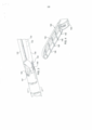
[00041] A FIG. 8 é outra vista em perspectiva truncada de componentes de dispositivo eletro cirúrgico que podem ser usados na modalidade da Figura 1 ou outras modalidades;[00041] FIG. 8 is another truncated perspective view of electrosurgical device components that may be used in the embodiment of Figure 1 or other embodiments;
[00042] A FIG. 9 é outra vista em perspectiva truncada de componentes de dispositivo eletro cirúrgico que podem ser usados na modalidade da Figura 1 ou outra modalidade, mostrando os componentes de um mecanismo de articulação, com alguns componentes removidos para maior clareza;[00042] FIG. 9 is another truncated perspective view of electrosurgical device components that may be used in the embodiment of Figure 1 or another embodiment, showing the components of a linkage mechanism, with some components removed for clarity;
[00043] A FIG. 10 é outra vista em perspectiva truncada dos componentes da FIG. 9, com alguns componentes removidos para maior clareza;[00043] FIG. 10 is another truncated perspective view of the components of FIG. 9, with some components removed for clarity;
[00044] A FIG. 11 é outra vista em perspectiva truncada dos componentes da FIG. 9, com alguns componentes removidos para maior clareza;[00044] FIG. 11 is another truncated perspective view of the components of FIG. 9, with some components removed for clarity;
[00045] A FIG. 12 é outra vista em perspectiva truncada dos componentes da FIG. 9, com alguns componentes removidos para maior clareza;[00045] FIG. 12 is another truncated perspective view of the components of FIG. 9, with some components removed for clarity;
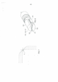
[00046] A FIG. 13 é uma vista plana de uma interface de giro entre os componentes que podem ser usados na modalidade da Figura 1 ou outras modalidades;[00046] FIG. 13 is a plan view of a pivoting interface between components that may be used in the embodiment of Figure 1 or other embodiments;
[00047] A FIG. 14 é outra vista em perspectiva truncada de um dispositivo eletro cirúrgico com componentes que podem ser removidos para mostrar a configuração de componentes internos que podem ser usados na modalidade da Figura 1 ou outras modalidades;[00047] FIG. 14 is another truncated perspective view of an electrosurgical device with components that can be removed to show the configuration of internal components that can be used in the embodiment of Figure 1 or other embodiments;
[00048] A FIG. 15 é uma vista de seção transversal parcial truncada alargada de um dispositivo eletro cirúrgico mostrando a configuração de componentes internos que podem ser usados na modalidade da Figura 1 ou outras modalidades;[00048] FIG. 15 is an enlarged truncated partial cross-sectional view of an electrosurgical device showing the configuration of internal components that may be used in the embodiment of Figure 1 or other embodiments;
[00049] A FIG. 16 é outra vista de seção transversal parcial truncada alargada de um dispositivo eletro cirúrgico mostrando a configuração de componentes internos que podem ser usados na modalidade da Figura 1 ou outras modalidades; e[00049] FIG. 16 is another enlarged truncated partial cross-sectional view of an electrosurgical device showing the configuration of internal components that may be used in the embodiment of Figure 1 or other embodiments; It is
[00050] A FIG. 17 é uma vista em perspectiva truncada de um dispositivo eletro cirúrgico mostrando a configuração de componentes internos que podem ser usados na modalidade da Figura 1 ou outras modalidades.[00050] FIG. 17 is a truncated perspective view of an electrosurgical device showing the configuration of internal components that may be used in the embodiment of Figure 1 or other embodiments.
[00051] Requerentes desenvolveram dispositivos eletro cirúrgicos melhorados que abordam a necessidade de tamanho reduzido, ao abordar também a necessidade de alta força de compressão entre os mordentes. Os dispositivos eletro cirúrgicos melhorados foram projetados usando uma abordagem holística que elimina, simplifica ou combina componentes individuais onde apropriado, ao maximizar a resistência e rigidez nos mordentes.[00051] Applicants have developed improved electrosurgical devices that address the need for reduced size, while also addressing the need for high compression force between jaws. The improved electrosurgical devices were designed using a holistic approach that eliminates, simplifies or combines individual components where appropriate, while maximizing strength and rigidity in the jaws.
[00052] Os exemplos a seguir ilustram recursos que são projetados para atender às necessidades concorrentes para o tamanho reduzido e para mordentes mais fortes. Embora diferentes recursos serão descritos e mostrados em um dispositivo eletro cirúrgico 100, muitos dos recursos são recursos independentes. Alguns ou todos esses recursos podem aparecer no mesmo dispositivo, mas não precisam ser no mesmo dispositivo e podem ser usados em diferentes combinações em diferentes modalidades da invenção. Dispositivos em conformidade com a invenção podem incluir muitos dos recursos do dispositivo e características mostradas e descritas nos pedidos de patente US 12/027,231 e 13/070,391, cujo conteúdo é incorporado por referência neste documento na sua totalidade.[00052] The following examples illustrate features that are designed to meet competing needs for reduced size and stronger jaws. Although different features will be described and shown in an
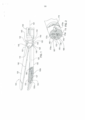
[00053] Referindo-se à Figura 1, um dispositivo eletro cirúrgico 100 é mostrado em conformidade com uma modalidade exemplar. Dispositivo 100 inclui uma haste alongada 102. A haste alongada 102 tem uma porção de extremidade distal 110 que apresenta um mordente superior 120 e um alojamento de mordente inferior 130. Alojamento de mordente inferior 130 contém um mordente inferior 132. Uma lâmina de corte 160, mostrada nas Figuras 2 e 3, é deslocável entre os mordentes superior e inferior 120 e 132 para cortar tecido.[00053] Referring to Figure 1, an
[00054] Mordente superior 120 e alojamento de mordente inferior 130 são unidas de forma passível de giro por uma conexão de giro 140 que permite que o mordente superior em relação ao alojamento de mordente inferior para abrir e fechar o mordente superior. Conexão de giro 140 inclui um elemento semicilíndrico 142 tendo uma superfície convexa 143 que encaixa em um primeiro lado 122 do mordente superior 120. Conexão de giro 140 também inclui uma superfície côncava em formato de arco 144 que encaixa um segundo lado 124 do mordente superior 120. Superfície convexa 143 e superfície côncava 144 seguem perfis circulares que são concêntricos em torno de um ponto de giro 148. Elemento semicilíndrico 142 e superfície côncava 144 são separados uns dos outros por uma passagem arqueada 145. As bordas da passagem arqueada 145 formam um curso ou canaleta 146, através da qual o mordente superior 120 desliza. O formato arqueado do curso 146 faz com que o mordente superior 120 gire em relação ao alojamento de mordente inferior 130 à medida que o mordente superior desliza através da passagem. Mordente superior 120 gira em torno do ponto de giro 148.[00054]
[00055] Como pode ser visto nas Figuras 1 e 3, a conexão de giro 140 difere de conexões de pino convencionais de maneira significativa. Como uma questão inicial, a conexão de giro 140 não exige a remoção do material dos mordentes. Mordente superior 120 cabe dentro do corpo do alojamento de mordente inferior 130 pela passagem arqueada 145, com pouco ou nenhum espaço vazio em ou ao redor do mordente superior e o alojamento de mordente inferior. Conexões de pino convencionais, em contrapartida, exigem a remoção do material para acomodar o pino e permitir que cada mordente para girar um em relação ao outro. Remoção de material dos mordentes reduz a massa dos mordentes e, consequentemente, a quantidade de força de compressão e rigidez que pode ser exercida sobre o tecido quando os mordentes estão fechados.[00055] As seen in Figures 1 and 3, the
[00056] A conexão de giro 140 também difere de conexões de pino convencionais no que diz respeito à posição da conexão de giro em relação aos mordentes. Conexões de pino estão normalmente localizados ao longo da linha mediana do instrumento entre os mordentes superior e inferior. O ponto de giro 148, em contraste, é deslocado de uma linha de centro 101 do dispositivo, adjacente à borda externa 121 do mordente superior 120. Este arranjo de deslocamento tem uma vantagem sobre conexões de pino transversais localizadas na linha mediana, porque ele provê um caminho desobstruído claro através da linha mediana. O caminho desobstruído permite que a lâmina de corte 160 percorra ao longo da linha mediana entre as lâminas, sem qualquer obstrução criada por um pino.[00056] The
[00057] A configuração do eletrodo no dispositivo 100 é outro recurso que equilibra a necessidade de tamanho reduzido e maior rigidez do mordente. Muitos dispositivos eletro cirúrgicos conhecidos usam um ou mais eletrodos autônomos colocados sobre os mordentes. Eletrodos autônomos exigem espaço para capturar, isolar e abrigar os eletrodos nos mordentes, sacrificando a rigidez nos mordentes. Para resolver este problema, o dispositivo 100 é projetado sem eletrodos autônomos. A alimentação é fornecida diretamente ao mordente superior 120 e alojamento de mordente inferior 130.[00057] The electrode configuration on
[00058] Dispositivos eletro cirúrgicos conhecidos fornecem alimentação para eletrodos usando cabos de transmissão de alimentação dedicada que se estendem através dos mordentes. Em muitos casos, estes cabos de transmissão de alimentação dedicada são em forma de cabos trançados ou encapados fixos. Os cabos de transmissão de alimentação dedicada ocupam uma quantidade significativa de espaço e exigem furos, passagens, etc. que removam material dos mordentes. Como tal, os cabos de transmissão de alimentação dedicada e seus furos diminuem a rigidez do mordente, reduzindo desse modo a quantidade de força de compressão que pode ser aplicada entre os mordentes durante a selagem. Os cabos de transmissão de alimentação dedicada também podem limitar o movimento do instrumento em casos onde os cabos dedicados não têm folga ou elasticidade suficiente para mover ou esticar conforme o instrumento se move.[00058] Known electrosurgical devices supply power to electrodes using dedicated power transmission cables that run through the jaws. In many cases, these dedicated power transmission cables are in the form of fixed braided or jacketed cables. Dedicated power transmission cables take up a significant amount of space and require drilling, routing, etc. that remove material from the jaws. As such, the dedicated power transmission cables and their holes decrease the stiffness of the jaw, thereby reducing the amount of compressive force that can be applied between the jaws during sealing. Dedicated power transmission cables can also limit instrument movement in cases where dedicated cables do not have enough slack or elasticity to move or stretch as the instrument moves.
[00059] Para preservar a rigidez nos mordentes e fornecer maior mobilidade e flexibilidade de instrumento, dispositivos em conformidade com a invenção incluem, preferencialmente, componentes multifuncionais que controlam tanto o movimento quanto o fornecimento de alimentação. Cabos de transmissão de alimentação dedicada que sacrificam a rigidez de mordente e mobilidade de instrumento são preferencialmente evitados. Fornecimento de energia pode ser provido através dos mesmos componentes que controlam a atuação e/ou articulação, por exemplo. Fornecimento de energia também pode ser provido através de componentes de tradução.[00059] To preserve rigidity in the jaws and provide greater instrument mobility and flexibility, devices in accordance with the invention preferably include multifunctional components that control both movement and power supply. Dedicated power transmission cables that sacrifice jaw rigidity and instrument mobility are preferably avoided. Power supply can be provided through the same components that control actuation and/or articulation, for example. Power supply can also be provided through translation components.
[00060] Referindo-se à Figura 2, uma seção transversal do dispositivo 100 é mostrada na seção de "pulso" ou "vértebra" 170. Seção de pulso 170, que é descrita em mais detalhes em uma seção posterior, inclui uma vértebra 173 que é substancialmente sólida, com exceção de quatro passagens. Duas passagens acomodam um cabo de articulação enrolado 167, e uma passagem acomoda um cabo de atuação enrolado 169. Cabo de articulação 167 é operável para permitir que a porção da extremidade distal do dispositivo dobre em relação ao eixo longitudinal do dispositivo. Cabo de atuação 169 é operável para abrir e fechar o mordente superior 120. Cabo de articulação 167 é enrolado através das passagens, formando duas seções de cabo de articulação geralmente paralelas 172 e 174. De forma semelhante, o cabo de atuação 169 é enrolado através das passagens, formando duas seções de cabo de atuação geralmente paralelas 176 e 178. Seções de cabo de atuação 176 e 178 cruzam uma sobre a outra na seção mostrada na Figura 2, como será explicado mais detalhadamente. As Figuras 3 e 14 mostram como cabo de articulação 167 e cabo de atuação 169 são roteadas através de uma porção de extremidade distal do dispositivo, com uma extremidade enrolada do cabo de articulação visível.[00060] Referring to Figure 2, a cross section of
[00061] Uma primeira passagem 173a localizada em uma seção periférica externa da vértebra 173 contém a primeira seção de cabo de articulação 172. Uma segunda passagem 173b localizada em outra seção periférica externa da vértebra 173 contém a segunda seção de cabo de articulação 174. Uma terceira passagem 173c localizada em uma seção interna da vértebra 173 contém lâmina de corte 160. Uma quarta passagem 173d localizada em uma seção interna da vértebra 173 contém seções de cabo de atuação 176 e 178.[00061] A
[00062] Alimentação é fornecida ao mordente superior 120 através do cabo de atuação 169. Alimentação é fornecida para o alojamento do mordente inferior 130 através do cabo de articulação 167 e pode também ser fornecida através de qualquer outra série de componentes metálicos, incluindo casquilhos, vértebra ou hastes de mordente que podem ser de metal e que entram em contato entre si em série e que são isolados do cabo de atuação 169. Alojamento de mordente inferior 130 e mordente inferior 132 ambos incluem superfícies metálicas em contato com um outro, de modo que a alimentação fornecida ao alojamento do mordente inferior é conduzida para o mordente inferior.[00062] Power is supplied to the
[00063] Superfícies no mordente superior 120 que interagem com alojamento do mordente inferior 130 e mordente inferior 132 devem ser eletricamente isoladas. Para abordar isso, o dispositivo 100 inclui uma película plástica 180 sobre o mordente superior 120. O mordente superior 120 é sobremoldado com a película de plástico 180 para isolar as superfícies que interagem com alojamento de mordente inferior 130. O sobremolde não exige afastamento entre componentes, preservar espaço para permitir que os mordentes tenham massa de material. Sobremoldar o mordente superior 120 também permite o deslocamento de recursos a serem criados no mordente superior, como será explicado na próxima seção.[00063] Surfaces on the
[00064] A película sobremoldada 180 tem funções múltiplas. Uma primeira função da película sobremoldada é isolar eletricamente o mordente superior 120 do alojamento do mordente inferior 130, como descrito acima. Uma segunda função da película sobremoldada é gerar recursos de deslocamento que criam um espaço de lacuna entre os eletrodos, ou seja, mordente inferior 120 e mordente inferior 132, quando os mordentes estão fechados. Na Figura 4, uma modalidade do dispositivo inclui recursos de deslocamento mostrados na forma de correias 150 que se estendem transversalmente por todo o mordente superior 120. Correias 150 são produzidas durante o processo de sobremoldagem. Uma terceira função da película sobremoldada é reduzir a temperatura do lado posterior do mordente que entra em contato com o tecido, de modo a reduzir o risco de queima de tecido.[00064] The
[00065] Recursos de deslocamento de geração de lacuna em conformidade com a invenção não precisam assumir a forma de correias transversais, e podem ser qualquer irregularidade de superfície ou a projeção que provê uma separação entre os eletrodos quando os mordentes estão fechados. Por exemplo, o mordente superior 120 pode incluir uma pluralidade de orifícios que recebem rebites ou membros semelhantes a rebites que se projetam a partir da superfície do mordente superior e entram em contato com o mordente inferior 132.[00065] Gap generation displacement features in accordance with the invention need not take the form of cross belts, and can be any surface irregularity or projection that provides a separation between the electrodes when the jaws are closed. For example, the
[00066] O mordente inferior 132 está conectado de forma passível de giro ao alojamento do mordente inferior 130 por uma conexão de giro do mordente inferior 190. A conexão de giro 190 entre o mordente inferior 132 e alojamento do mordente inferior 130 representa uma das áreas mais críticas onde a rigidez e resistência devem ser maximizadas no mordente inferior para prover força de compressão suficiente. Conexões de pinos e furos exigem a remoção de material a partir do mordente inferior, reduzindo rigidez e força do mordente, como descrito acima. Portanto, a conexão de giro 190 apresenta uma conexão "sem pinos" na forma de um par de saliências 136. Saliências 136 projetam-se exteriormente a partir do mordente inferior 132 e ajustam-se em pequenas aberturas 138 no alojamento do mordente inferior 130. Com este arranjo, nenhum material é removido do mordente inferior 132 em toda a largura do mordente no local da conexão de giro 190.[00066] The
[00067] Como uma alternativa para as saliências e aberturas, alojamento do mordente inferior 130 pode ser levemente comprimido para criar uma interface de giro entre o alojamento de mordente inferior e mordente inferior 132.[00067] As an alternative to protrusions and openings, the
[00068] Referindo-se à Figura 5, o mordente 132 tem uma superfície de fundo convexa arredondada 133 e alojamento do mordente inferior 130 tem uma superfície interna côncava arredondada 131. Superfície interna côncava 131 encosta na superfície de fundo convexa 133 quando o alojamento de mordente inferior 130 é girado em relação ao mordente superior 120. Como tal, a superfície interna côncava 131 e a superfície de fundo convexa 133 formam superfícies de suporte que absorvem a força de compressão entre o mordente inferior 132 e o alojamento do mordente inferior 130 e direcionam a força de compressão para longe das saliências 136 e aberturas 138. Consequentemente, a integridade estrutural do mordente inferior 132 não depende muito da força das saliências 136 ou da conexão de giro 190.[00068] Referring to Figure 5, the
[00069] Um dos desafios de um dispositivo de articulação é transmitir o movimento através dos membros articulados. Quando o dispositivo se curva, o comprimento do arco através da junta muda conforme você se move longe da linha central. Isso geralmente exige o uso de membros de atuação altos (para força) e finos (para flexibilidade) que se movem ao longo da linha central do dispositivo. Articulação para esquerda e direita impede o uso de membros de atuação curtos e planos ou membros de cabo emparelhados dispostos perpendicularmente ao plano de articulação, porque os membros ou cabos se curvarão e/ou transmitirão movimento e força de forma desigual.[00069] One of the challenges of an articulating device is transmitting motion through the articulating members. When the device bends, the length of the arc across the joint changes as you move away from the centerline. This often calls for the use of tall (for strength) and thin (for flexibility) actuation members that move along the centerline of the device. Left and right articulation precludes the use of short, flat actuating members or paired cable members arranged perpendicular to the plane of articulation, because the members or cables will bend and/or transmit motion and force unevenly.
[00070] O dispositivo 100 usa um cabo de atuação 169 que está enrolado para formar um par de seções de cabo paralelo 176 e 178, como mencionado acima. Seções de cabo de atuação 176 e 178 são configuradas para girar o mordente superior 120 em relação ao alojamento do mordente inferior 130 quando a força é aplicada através das seções de cabo de atuação. Cabo de atuação enrolado 169 é conectado a um pino (não mostrado) no mordente superior 120. Para girar o mordente superior 120 para uma posição aberta, uma força empurrando (ou força direcionada para a porção de extremidade distal 110) é aplicada ao mordente superior através de seções de cabo de atuação 176 e 178. Para girar o mordente superior 120 para uma posição fechada, uma força de tração (ou força de tensão direcionada para longe da porção de extremidade distal 110) é aplicada ao mordente superior através de seções de cabo de atuação 176 e 178. Cada uma das seções de cabo de atuação 176 e 178 é definida a partir da linha central do plano de articulação, mas em um arranjo que permite que os cabos empurrem ou puxem igualmente da esquerda para a direita. A solução é torcer os cabos em 180 graus, cruzando no meio os membros da articulação em um ponto de cruzamento P.[00070] The
[00071] A Figura 2 é uma vista de seção transversal do dispositivo 100 feita através de um plano que intercepta o ponto de cruzamento P, onde a seção de cabo de atuação 176 cruza sobre a seção de cabo de atuação 178. A Figura 14 é uma vista em perspectiva da extremidade distal do dispositivo 100, com componentes removidos para mostrar como a seção de cabo 176 atravessa a seção de cabo 178 no ponto P. A Figura 15 é uma vista de seção transversal do dispositivo 100 que mostra como o cabo de atuação 169 conecta-se com o mordente superior 120. O cabo de atuação 169 é enrolado através de uma ranhura em formato de U 125 formada em uma porção de base do mordente superior 120. As Figuras 16 e 17 são vistas de seção transversal do dispositivo 100 que mostram como cabos de atuação 176 e 178 conectam- se com a extremidade proximal do dispositivo. O cruzamento de cabos de atuação 176 e 178 resulta em comprimentos de arco através da região de articulação que são imagens espelhadas uma da outra e mantêm o mesmo comprimento. Os comprimentos do arco são ilustrados esquematicamente na Figura 7. O ponto de cruzamento P age como um ponto de giro para os cabos. Ao manter comprimentos de arco iguais, as forças são equilibradas entre as seções de cabo de atuação 176 e 178, mesmo quando as seções de cabo de atuação são dobradas durante a articulação dos mordentes, de modo que as seções de cabo puxem uniformemente o mordente superior e representam mínima resistência para os cabos de articulação 172 e 174. Seções de cabo de articulação 172 e 174 são mantidas em um estado de tensão, de modo que os componentes do sistema são mantidos juntos em tensão, permitindo que os mordentes se abram e fechem adequadamente e permitam que a extremidade distal do dispositivo se articule adequadamente.[00071] Figure 2 is a cross-sectional view of the
[00072] Referindo-se à Figura 8, o mordente superior 120 tem uma superfície de junção 131 que se junta ao mordente inferior 132. O mordente inferior 132 tem, de forma semelhante, uma superfície de junção 133 que se junta ao mordente superior 120. Superfícies de junção 131 e 133 têm, cada um, um contorno em formato de V, como mostrado, que provê várias vantagens sobre as superfícies planas de junção.[00072] Referring to Figure 8, the
[00073] O contorno em formato de V provê um recurso de auto alinhamento que mantém o mordente superior 120 e o mordente inferior 132 alinhados entre si. O recurso de auto alinhamento elimina a necessidade de longos comprimentos de componente e geometria de tolerância apertada atrás dos mordentes para controlar o alinhamento. As superfícies de junção em formato de V 131 e 133 também têm áreas de superfície maiores do que superfícies planas, resultando em uma área incrementalmente mais larga para encaixar o tecido.[00073] The V-shaped contour provides a self-alignment feature that keeps the
[00074] A linha de centro axial 123 da superfície de junção 131 atende a linha de centro axial 135 da superfície de junção 133 ao longo de uma linha 137 que é deslocada de uma linha de centro 101 do dispositivo 100. Neste arranjo, o plano de corte 103 pode ser movido para longe da linha central 101 do dispositivo 100, permitindo que a lâmina de corte 160 seja localizada longe do centro, de modo que outros componentes possam ser posicionados em direção ao centro do dispositivo.[00074] The axial centerline 123 of the
[00075] Referindo-se à Figura 1, alojamento de mordente inferior 130 contém uma mola do mordente inferior 134 entre o alojamento do mordente inferior e mordente inferior 132. A mola do mordente inferior 134 encosta no interior do alojamento do mordente inferior 130 para girar o mordente inferior 132. Nesta configuração, a mola de mordente inferior 134 polariza uma porção distal 137 do mordente inferior 132 para o mordente superior 120.[00075] Referring to Figure 1,
[00076] Dispositivos eletro cirúrgicos conhecidos que incluem molas de mordente inferior colocam a mola em uma seção proximal do mordente inferior, em um ponto localizado proximalmente em relação ao ponto de giro. Para prover espaço para a mola, uma certa quantidade de material é removida da porção proximal do mordente inferior, e/ou do alojamento de mordente inferior em uma área similar. Esta remoção do material pode criar uma diminuição substancial de força e rigidez na seção proximal do mordente inferior e/ou alojamento de mordente inferior. Rigidez e resistência de mordente são especialmente importantes na seção proximal do mordente inferior e alojamento de mordente porque a seção proximal é uma área crítica para prover a força de compressão. A Figura 1 mostra a espessura relativa do mordente inferior 132 na sua seção proximal 135 e sua seção distal 137.[00076] Known electrosurgical devices that include lower jaw springs place the spring in a proximal section of the lower jaw, at a point located proximally to the pivot point. To provide space for the spring, a certain amount of material is removed from the proximal portion of the lower wedge, and/or the lower wedge seat in a similar area. This removal of material can create a substantial decrease in strength and stiffness in the proximal section of the lower wedge and/or lower wedge seat. Wedge stiffness and strength are especially important in the proximal section of the lower wedge and wedge seat because the proximal section is a critical area for providing compressive strength. Figure 1 shows the relative thickness of the
[00077] Para evitar a perda de força de mordente e rigidez na porção proximal 135 do mordente inferior, 132, a mola do mordente inferior 134 está localizada na porção distal 137 do mordente inferior. Isso preserva mais massa em torno da seção proximal 135 onde é necessário. A seção distal 137 do mordente inferior 132 tem mais massa para começar do que a seção proximal 135 e, portanto, é mais adequada para acomodar a mola de mordente inferior 134.[00077] To prevent loss of wedge strength and rigidity in the
[00078] A mola de mordente inferior 134 encaixa por atrito o mordente inferior 132 em dois lugares, 132a e 132b. Este encaixe nos dois locais auxilia na transferência de energia a partir do alojamento de mordente inferior 130 para o mordente inferior 132.[00078] The lower jaw spring 134 frictionally fits the
[00079] As Figuras 9-12 mostram um mecanismo de articulação 200 em conformidade com a invenção. O mecanismo de articulação 200 controla o movimento de dobra ou giratório na seção de pulso 170, a qual permite que o mordente superior 120 e mordente inferior 132 dobrem à esquerda ou à direita. Mais especificamente, o mecanismo de articulação 200 é operável para aplicar uma força de tensão a uma das seções de cabo de articulação 172 e 174 para dobrar o dispositivo na seção de pulso 170.[00079] Figures 9-12 show a
[00080] O mecanismo de articulação 200 inclui um par de discos 210 que mantêm a posição articulada dos mordentes superior e inferior 120 e 132. O mecanismo articulador 200 também inclui um articulador 220 operável para rodar os discos 210. O articulador 220 tem um par de alças 222 que estendem-se exteriormente a partir dos discos 210. Alças 222 e discos 210 são rotativamente deslocáveis em um alojamento 230. O alojamento 230 tem uma parede interna 232 forrada com entalhes de catraca 234. Cada disco 210 tem um par de braços 212 operáveis para encaixar e desencaixar os entalhes da catraca 234 quando o disco 210 é rodado no alojamento 230. Entalhes de catraca 234 são separados uns dos outros por uma série de dentes da catraca apontando interiormente 235. Cada braço 212 tem uma extremidade distal 213 com uma ponta pontiaguda 215 configurada para interagir de forma deslizável e encaixar com entalhes de catraca 234 e dentes da catraca 235 como discos 210 rodam no alojamento. Braços 212 são formados de material flexível resistente que permite que os braços flexionem ou dobrem-se radialmente e interiormente em direção ao centro dos discos 210, em resposta ao contato entre a ponta 215 e os dentes 235. Quando pontas 215 encaixam as seções mais internas de dentes da catraca 235, braços 212 dobram-se interiormente sob a energia armazenada. À medida que discos 210 rodam e as pontas 215 se alinham com entalhes de catraca 234, braços 212 ajustam-se exteriormente e retornam a um estado relaxado com as pontas posicionadas nos entalhes da catraca.[00080] The
[00081] O mecanismo de articulação 200 inclui um mecanismo de centralização 240 que polariza o articulador 220 para uma condição centralizada ou "neutra". A condição neutra é mostrada na Figura 9. O mecanismo de centralização 240 inclui um par de molas de lâmina flexíveis 216 que se estendem desde cada disco 210. Cada mola de lâmina 216 tem uma extremidade distal 217 que é mantida em uma posição cativa entre um par de projeções 226 no articulador 220. Quando o articulador 220 está na condição neutra, cada mola de lâmina 216 está substancialmente em linha reta, em um estado relaxado. Quando o articulador 220 começa a rodar à esquerda ou à direita, projeções 226 também rodam, mas os discos 210 não rodam imediatamente e, em vez disso, permanecem parados, como será explicado em mais detalhes abaixo. Como tal, cada mola de lâmina 216 dobra-se em resposta ao movimento inicial das projeções 226, armazenando energia na mola de lâmina que cria uma força de polarização. A força de polarização em cada mola de lâmina 216 aplica força ao articulador 220 na direção oposta à direção na qual o articulador foi rodado, para instar o articulador de volta para a condição neutra. Quando a força de rotação é liberada do articulador 200, a força de polarização das molas de lâmina 216 retorna o articulador 200 de volta à condição neutra.[00081] The
[00082] O mecanismo de articulação 200 inclui, adicionalmente, um mecanismo de travamento automático 250. O mecanismo de travamento 250 é um mecanismo de bloqueio passivo que impede a força externa sobre os mordentes superior e inferior 120 e 132 de mover os mordentes fora de sua posição indexada. O mecanismo de travamento 250 inclui quatro retentores 228 sobre o articulador 220, dois dos quais são visíveis nas Figuras e dois que estão no lado oposto do articulador. Cada retentor 228 é móvel em relação aos discos 210 entre uma posição de travamento e uma posição de liberação. Na posição de travamento, mostrada na Figura 9, cada retentor 228 é alinhado com uma projeção interna 219 em um dos braços 212. Nesta posição, projeções internas 219 bloqueiam os braços e os impedem de dobrarem-se interiormente, impedindo, desse modo, os braços de desencaixe dos entalhes de catraca e impossibilitando a articulação dos mordentes de sua posição indexada. Na posição de liberação, mostrada na Figura 10, cada retentor 228 é rodado fora de alinhamento com a projeção interna correspondente 219, permitindo que os braços dobrem-se interiormente e desencaixem os entalhes de catraca para facilitar a articulação dos mordentes para outra posição.[00082] The
[00083] Neste arranjo, o mecanismo de articulação 200 é um mecanismo de flutuação que está inclinado para a condição neutra em relação aos discos. Em operação, os mordentes são articulados ao rodar o articulador 220 no sentido horário ou anti-horário relativo a alojamento 230 através das alças 222. Quando a força de rotação é inicialmente aplicada a alças 222, a força aplicada se opõe às forças de centralização de molas de lâmina 216. Se a força aplicada for maior que as forças de centralização, o articulador 220 rodará em relação aos discos 210 de modo que os retentores 228 movem-se fora da posição de travamento para a posição de liberação.[00083] In this arrangement, the
[00084] O articulador 220 tem quatro bordas de contato 225 e discos 210 possuem bordas de contato correspondente 211. Quando o articulador está na condição neutra, bordas de contato 211 são espaçadas de bordas de contato 225, criando pequenas lacunas 229 que definem limites de percurso. Após a rotação inicial de alças 222, o articulador 220 rodará e duas das bordas de contato 225 aproximarão as bordas de contato 211 correspondentes nos discos 210. Após as alças 222 sofrerem rotação através de um ângulo limiar pequeno de rotação, tal como 5 graus, as bordas de contato 225 se aproximando das bordas de contato 211 nos discos 210 irão atingir seu limite de percurso e entrar em contato com os discos 210. Neste ponto, força rotacional aplicada nas alças será transferida para discos 210 e rodar os discos em tandem com o articulador 220. À medida que os discos 210 rodam, as pontas 215 de braços 212 dobram interiormente conforme eles se encaixam de forma deslizável nos dentes da catraca 235 e ajustam-se exteriormente conforme eles se alinham com entalhes de catraca 234 na próxima posição indexada. Ao atingir uma posição indexada desejada, força de rotação é liberada das alças 222, de modo que as molas de lâmina 216 retornem o articulador 220 à condição neutra, com retentores 228 de volta para a posição de travamento. Na posição de travamento, retentores 228 impedem que os braços 212 desencaixem os entalhes de catraca 234, travando eficazmente cabos de articulação 172 e 174 e pulso 170 na posição indexada.[00084] The
[00085] Referindo-se a Figuras 11 e 12, o dispositivo 100 inclui uma mola plana 260 que está anexada às extremidades proximais dos cabos de articulação 172 e 174. A mola plana 260 coloca cabos de articulação 172 e 174 em tensão para fixar componentes no pulso 170 juntos, evitando, desse modo, a necessidade de utilizar outros meios para unir fisicamente os componentes de pulso. Os discos 210 mantêm a mola plana 260 no lugar no alojamento 230. Cada cabo de articulação 172 e 174 estende-se através de um orifício em uma porção de asa 262 da mola plana 260. A extremidade proximal de cada cabo de articulação 172 e 174 é dobrada e capturada em um batente de cabo 270. Cada batente de cabo 270 é introduzido para manter sua orientação contra a mola plana 260. Cada porção de asa 262 tem um estado relaxado, no qual a porção de asa é dobrada no sentido proximal em relação ao resto da mola plana 260. No estado montado, os batentes de cabo 270 são impulsionados distalmente contra porções de asa 262 para tração do mecanismo de articulação 200.[00085] Referring to Figures 11 and 12, the
[00086] Modalidades podem incluir um mecanismo de pulso com componentes tendo interfaces de giro "não circular". Por exemplo, as interfaces de giro entre os componentes podem ter geometrias parabólicas, escalonadas ou entalhadas em V, resultando em um eixo de rotação em movimento, em vez de um tradicional eixo fixo de rotação associado com geometrias estritamente "circulares", tais como geometrias de interface esférica ou cilíndrica. O eixo em movimento de rotação provê o benefício de um acoplamento de auto alinhamento ou auto centralização no qual as vértebras adjuntas são instadas a retornar para uma configuração em linha reta após ser articuladas. Esta inclinação em direção a uma configuração em linha reta estabiliza a posição dos mordentes e provê resistência contra deslocamento quando os mordentes estão travados ou em contato com outros objetos.[00086] Embodiments may include a pulse mechanism with components having "non-circular" turning interfaces. For example, the rotating interfaces between components can have parabolic, stepped, or V-notch geometries, resulting in a moving axis of rotation rather than the traditional fixed axis of rotation associated with strictly "circular" geometries, such as spherical or cylindrical interface. The rotating axis provides the benefit of a self-aligning or self-centering coupling in which the adjoining vertebrae are urged to return to a straight-line configuration after being articulated. This tilt towards a straight line configuration stabilizes the position of the jaws and provides resistance against displacement when the jaws are locked or in contact with other objects.
[00087] A interface não circular também combate a perda de força de compressão exibida pelos mordentes quando os mordentes estão articulados por alongamento do comprimento de haste eficaz. Em dispositivos que têm um mecanismo do tipo "puxar" para fechar os mordentes, alongar a haste (sem alterações no mecanismo de travamento do mordente) resultará em puxada com mais força para mais força de compressão.[00087] The non-circular interface also combats the loss of compressive strength exhibited by the jaws when the jaws are hinged by elongating the effective shank length. In devices that have a "pull" type mechanism to close the jaws, lengthening the stem (without changes to the jaw locking mechanism) will result in a harder pull for more compression force.
[00088] A Figura 13 mostra um exemplo de uma interface não circular 171 entre vértebra 173 e um casquilho 182 na seção de pulso 170. A interface não circular 171 inclui uma superfície de junção convexa arredondada 175 na vértebra 173 e uma superfície de junção côncava arredondada 184 no casquilho 182. Um degrau ou "ressalto" 177 se estende exteriormente desde a superfície de junção convexa 175. As transições de superfície entre o ressalto 175 e superfície de junção convexa 177 são arredondadas, formando uma suave curvatura composta ao longo da borda da vértebra 173. Um recesso 185 se estende até a superfície de junção côncava 184 e tem um formato que conforma-se à geometria do ressalto 177, como mostrado.[00088] Figure 13 shows an example of a non-circular interface 171 between
[00089] Quando a seção de pulso 170 é reta (ou seja, quando as vértebras não estão articuladas e os mordentes estão em linha reta), a superfície de junção convexa 175 e ressalto 177 estão em fase com a superfície de junção côncava 184 e recesso 185, com o ressalto aninhado no recesso. Quando a seção de pulso 170 é articulada, a superfície de junção convexa 175 e o ressalto 177 são deslocados fora de fase com a superfície de junção côncava 184 e recesso 185, tal que o ressalto se move para fora do recesso e encaixa a superfície de junção côncava. Nesta condição, a distância entre a vértebra 173 e o casquilho 182 é incrementalmente aumentada, deslocando o eixo de rotação entre as partes. A dimensão do ressalto 177 pode ser muito pequena em relação ao tamanho da superfície de junção convexa 175. O perímetro arredondado do ressalto 177 pode projetar-se tão pouco quanto 0,002 polegadas desde a superfície de junção convexa 175. Configurações de menor ou maior ressalto também podem ser usadas.[00089] When the
Claims (14)
Applications Claiming Priority (3)
| Application Number | Priority Date | Filing Date | Title |
|---|---|---|---|
| US201261705721P | 2012-09-26 | 2012-09-26 | |
| US61/705,721 | 2012-09-26 | ||
| PCT/IB2013/002133 WO2014049423A1 (en) | 2012-09-26 | 2013-09-26 | Apparatus for tissue cutting and sealing |
Publications (2)
| Publication Number | Publication Date |
|---|---|
| BR112015006554A2 BR112015006554A2 (en) | 2017-08-08 |
| BR112015006554B1 true BR112015006554B1 (en) | 2023-01-17 |
Family
ID=49681068
Family Applications (3)
| Application Number | Title | Priority Date | Filing Date |
|---|---|---|---|
| BR122020022677-3A BR122020022677B1 (en) | 2012-09-26 | 2013-09-26 | ELECTRO SURGICAL DEVICE FOR CUTTING AND SEALING TISSUES |
| BR122020022695-1A BR122020022695B1 (en) | 2012-09-26 | 2013-09-26 | ELECTRO SURGICAL DEVICE FOR CUTTING AND SEALING TISSUES |
| BR112015006554-6A BR112015006554B1 (en) | 2012-09-26 | 2013-09-26 | ELECTRO SURGICAL DEVICE FOR CUTTING AND SEALING TISSUES |
Family Applications Before (2)
| Application Number | Title | Priority Date | Filing Date |
|---|---|---|---|
| BR122020022677-3A BR122020022677B1 (en) | 2012-09-26 | 2013-09-26 | ELECTRO SURGICAL DEVICE FOR CUTTING AND SEALING TISSUES |
| BR122020022695-1A BR122020022695B1 (en) | 2012-09-26 | 2013-09-26 | ELECTRO SURGICAL DEVICE FOR CUTTING AND SEALING TISSUES |
Country Status (8)
| Country | Link |
|---|---|
| US (1) | US9872724B2 (en) |
| EP (4) | EP2997922B1 (en) |
| JP (4) | JP6336451B2 (en) |
| KR (3) | KR102210195B1 (en) |
| CN (3) | CN107252348B (en) |
| BR (3) | BR122020022677B1 (en) |
| ES (4) | ES2628848T3 (en) |
| WO (1) | WO2014049423A1 (en) |
Families Citing this family (14)
| Publication number | Priority date | Publication date | Assignee | Title |
|---|---|---|---|---|
| US9872724B2 (en) * | 2012-09-26 | 2018-01-23 | Aesculap Ag | Apparatus for tissue cutting and sealing |
| WO2017022287A1 (en) * | 2015-08-05 | 2017-02-09 | オリンパス株式会社 | Treatment tool |
| US11076908B2 (en) * | 2016-06-02 | 2021-08-03 | Gyrus Acmi, Inc. | Two-stage electrosurgical device for vessel sealing |
| US10149726B2 (en) * | 2016-07-01 | 2018-12-11 | Ethicon Endo-Surgery, Llc | Methods, systems, and devices for initializing a surgical tool |
| KR20190119094A (en) * | 2017-02-27 | 2019-10-21 | 아사히 인텍크 가부시키가이샤 | Manipulator |
| US10932845B2 (en) | 2017-04-27 | 2021-03-02 | Ethicon Llc | Detent feature for articulation control in surgical instrument |
| GB2565575A (en) * | 2017-08-17 | 2019-02-20 | Creo Medical Ltd | Electrosurgical apparatus for delivering RF and/or microwave energy into biological tissue |
| CN108186081B (en) * | 2017-12-18 | 2019-12-17 | 南京天朗制药有限公司 | Surgical forceps with shearing function for hospital operating room |
| USD904611S1 (en) | 2018-10-10 | 2020-12-08 | Bolder Surgical, Llc | Jaw design for a surgical instrument |
| JP1650796S (en) * | 2019-01-25 | 2020-01-20 | ||
| USD961074S1 (en) * | 2019-01-25 | 2022-08-16 | Karl Storz Se & Co. Kg | Shaft attachable medical instrument |
| USD966513S1 (en) * | 2019-01-25 | 2022-10-11 | Karl Storz Se & Co. Kg | Shaft attachable medical instrument |
| JP1650795S (en) * | 2019-01-25 | 2020-01-20 | ||
| US11813017B2 (en) | 2019-03-11 | 2023-11-14 | Microline Surgical, Inc. | Reusable minimally invasive surgical instrument |
Family Cites Families (536)
| Publication number | Priority date | Publication date | Assignee | Title |
|---|---|---|---|---|
| US2723108A (en) | 1951-02-24 | 1955-11-08 | Diamond Alkali Co | Valve |
| US3356408A (en) | 1966-07-07 | 1967-12-05 | Herbert D Sturtz | Camper anchoring device |
| US3527224A (en) | 1967-09-05 | 1970-09-08 | American Cyanamid Co | Method of surgically bonding tissue together |
| US3742955A (en) | 1970-09-29 | 1973-07-03 | Fmc Corp | Fibrous collagen derived product having hemostatic and wound binding properties |
| US3709215A (en) | 1970-12-28 | 1973-01-09 | S Richmond | Anterior vaginal retractor for vaginal surgery |
| US3845771A (en) | 1973-04-24 | 1974-11-05 | W Vise | Electrosurgical glove |
| DE2324658B2 (en) | 1973-05-16 | 1977-06-30 | Richard Wolf Gmbh, 7134 Knittlingen | PROBE FOR COAGULATING BODY TISSUE |
| JPS5239596B2 (en) | 1974-04-04 | 1977-10-06 | ||
| US3987795A (en) | 1974-08-28 | 1976-10-26 | Valleylab, Inc. | Electrosurgical devices having sesquipolar electrode structures incorporated therein |
| US4231372A (en) | 1974-11-04 | 1980-11-04 | Valleylab, Inc. | Safety monitoring circuit for electrosurgical unit |
| US4072153A (en) | 1976-03-03 | 1978-02-07 | Swartz William H | Post hysterectomy fluid drainage tube |
| US4041952A (en) | 1976-03-04 | 1977-08-16 | Valleylab, Inc. | Electrosurgical forceps |
| US4094320A (en) | 1976-09-09 | 1978-06-13 | Valleylab, Inc. | Electrosurgical safety circuit and method of using same |
| US5133727A (en) * | 1990-05-10 | 1992-07-28 | Symbiosis Corporation | Radial jaw biopsy forceps |
| WO1981003271A1 (en) | 1980-05-13 | 1981-11-26 | American Hospital Supply Corp | A multipolar electrosurgical device |
| US4492231A (en) | 1982-09-17 | 1985-01-08 | Auth David C | Non-sticking electrocautery system and forceps |
| US4590934A (en) | 1983-05-18 | 1986-05-27 | Jerry L. Malis | Bipolar cutter/coagulator |
| JPS61501068A (en) | 1984-01-30 | 1986-05-29 | ハルコフスキイ ナウチノ−イススレドワテルスキイ インスチチユ−ト オブスチエイ イ ネオトロジノイ ヒルルギイ | bipolar electrosurgical instrument |
| US5117118A (en) | 1988-10-19 | 1992-05-26 | Astex Co., Ltd. | Photoelectric switch using an integrated circuit with reduced interconnections |
| US4972846A (en) | 1989-01-31 | 1990-11-27 | W. L. Gore & Associates, Inc. | Patch electrodes for use with defibrillators |
| US5234425A (en) | 1989-03-03 | 1993-08-10 | Thomas J. Fogarty | Variable diameter sheath method and apparatus for use in body passages |
| US4979948A (en) | 1989-04-13 | 1990-12-25 | Purdue Research Foundation | Method and apparatus for thermally destroying a layer of an organ |
| US4976717A (en) | 1989-04-24 | 1990-12-11 | Boyle Gary C | Uterine retractor for an abdominal hysterectomy and method of its use |
| US5151102A (en) | 1989-05-31 | 1992-09-29 | Kyocera Corporation | Blood vessel coagulation/stanching device |
| US5041101A (en) | 1989-06-05 | 1991-08-20 | Helix Medical, Inc. | Hysterectomy drain appliance |
| US4998527A (en) | 1989-07-27 | 1991-03-12 | Percutaneous Technologies Inc. | Endoscopic abdominal, urological, and gynecological tissue removing device |
| US5007908A (en) | 1989-09-29 | 1991-04-16 | Everest Medical Corporation | Electrosurgical instrument having needle cutting electrode and spot-coag electrode |
| US5217030A (en) | 1989-12-05 | 1993-06-08 | Inbae Yoon | Multi-functional instruments and stretchable ligating and occluding devices |
| US6099550A (en) | 1989-12-05 | 2000-08-08 | Yoon; Inbae | Surgical instrument having jaws and an operating channel and method for use thereof |
| US5665100A (en) | 1989-12-05 | 1997-09-09 | Yoon; Inbae | Multifunctional instrument with interchangeable operating units for performing endoscopic procedures |
| US5035696A (en) | 1990-02-02 | 1991-07-30 | Everest Medical Corporation | Electrosurgical instrument for conducting endoscopic retrograde sphincterotomy |
| EP0448857A1 (en) | 1990-03-27 | 1991-10-02 | Jong-Khing Huang | An apparatus of a spinning type of resectoscope for prostatectomy |
| US5108408A (en) | 1990-04-20 | 1992-04-28 | Lally James J | Uterine-ring hysterectomy clamp |
| US5078736A (en) | 1990-05-04 | 1992-01-07 | Interventional Thermodynamics, Inc. | Method and apparatus for maintaining patency in the body passages |
| US5482054A (en) | 1990-05-10 | 1996-01-09 | Symbiosis Corporation | Edoscopic biopsy forceps devices with selective bipolar cautery |
| US5037379A (en) | 1990-06-22 | 1991-08-06 | Vance Products Incorporated | Surgical tissue bag and method for percutaneously debulking tissue |
| US5282799A (en) | 1990-08-24 | 1994-02-01 | Everest Medical Corporation | Bipolar electrosurgical scalpel with paired loop electrodes |
| DE4032471C2 (en) | 1990-10-12 | 1997-02-06 | Delma Elektro Med App | Electrosurgical device |
| US5190541A (en) | 1990-10-17 | 1993-03-02 | Boston Scientific Corporation | Surgical instrument and method |
| US5085659A (en) | 1990-11-21 | 1992-02-04 | Everest Medical Corporation | Biopsy device with bipolar coagulation capability |
| US5178618A (en) | 1991-01-16 | 1993-01-12 | Brigham And Womens Hospital | Method and device for recanalization of a body passageway |
| US5370647A (en) | 1991-01-23 | 1994-12-06 | Surgical Innovations, Inc. | Tissue and organ extractor |
| US5219895A (en) | 1991-01-29 | 1993-06-15 | Autogenesis Technologies, Inc. | Collagen-based adhesives and sealants and methods of preparation and use thereof |
| US5749895A (en) | 1991-02-13 | 1998-05-12 | Fusion Medical Technologies, Inc. | Method for bonding or fusion of biological tissue and material |
| US5156613A (en) | 1991-02-13 | 1992-10-20 | Interface Biomedical Laboratories Corp. | Collagen welding rod material for use in tissue welding |
| AU660444B2 (en) | 1991-02-15 | 1995-06-29 | Ingemar H. Lundquist | Torquable catheter and method |
| US5300087A (en) | 1991-03-22 | 1994-04-05 | Knoepfler Dennis J | Multiple purpose forceps |
| US5396900A (en) | 1991-04-04 | 1995-03-14 | Symbiosis Corporation | Endoscopic end effectors constructed from a combination of conductive and non-conductive materials and useful for selective endoscopic cautery |
| DE4113037A1 (en) | 1991-04-22 | 1992-10-29 | Sutter Hermann Select Med Tech | BIPOLAR COAGULATION AND / OR CUTTING INSTRUMENT |
| US5391166A (en) | 1991-06-07 | 1995-02-21 | Hemostatic Surgery Corporation | Bi-polar electrosurgical endoscopic instruments having a detachable working end |
| US5484436A (en) | 1991-06-07 | 1996-01-16 | Hemostatic Surgery Corporation | Bi-polar electrosurgical instruments and methods of making |
| US5324289A (en) | 1991-06-07 | 1994-06-28 | Hemostatic Surgery Corporation | Hemostatic bi-polar electrosurgical cutting apparatus and methods of use |
| DE4130064A1 (en) | 1991-09-11 | 1993-03-18 | Wolf Gmbh Richard | ENDOSCOPIC COAGULATION GRIPPER |
| US5273524A (en) | 1991-10-09 | 1993-12-28 | Ethicon, Inc. | Electrosurgical device |
| US5326013A (en) | 1991-10-18 | 1994-07-05 | United States Surgical Corporation | Self contained gas powered surgical apparatus |
| US5478003A (en) | 1991-10-18 | 1995-12-26 | United States Surgical Corporation | Surgical apparatus |
| US5711472A (en) | 1991-10-18 | 1998-01-27 | United States Surgical Corporation | Self contained gas powered surgical apparatus |
| US5312023A (en) | 1991-10-18 | 1994-05-17 | United States Surgical Corporation | Self contained gas powered surgical apparatus |
| US6250532B1 (en) | 1991-10-18 | 2001-06-26 | United States Surgical Corporation | Surgical stapling apparatus |
| US5207691A (en) | 1991-11-01 | 1993-05-04 | Medical Scientific, Inc. | Electrosurgical clip applicator |
| AU665584B2 (en) | 1991-11-01 | 1996-01-11 | Medical Scientific, Inc. | Electrosurgical cutting tool |
| US5531744A (en) | 1991-11-01 | 1996-07-02 | Medical Scientific, Inc. | Alternative current pathways for bipolar surgical cutting tool |
| US5713896A (en) | 1991-11-01 | 1998-02-03 | Medical Scientific, Inc. | Impedance feedback electrosurgical system |
| US5665085A (en) | 1991-11-01 | 1997-09-09 | Medical Scientific, Inc. | Electrosurgical cutting tool |
| DE4138116A1 (en) | 1991-11-19 | 1993-06-03 | Delma Elektro Med App | MEDICAL HIGH-FREQUENCY COAGULATION CUTTER |
| US6024733A (en) | 1995-06-07 | 2000-02-15 | Arthrocare Corporation | System and method for epidermal tissue ablation |
| US5697882A (en) | 1992-01-07 | 1997-12-16 | Arthrocare Corporation | System and method for electrosurgical cutting and ablation |
| US6053172A (en) | 1995-06-07 | 2000-04-25 | Arthrocare Corporation | Systems and methods for electrosurgical sinus surgery |
| US6142992A (en) | 1993-05-10 | 2000-11-07 | Arthrocare Corporation | Power supply for limiting power in electrosurgery |
| US5681282A (en) | 1992-01-07 | 1997-10-28 | Arthrocare Corporation | Methods and apparatus for ablation of luminal tissues |
| US5484435A (en) | 1992-01-15 | 1996-01-16 | Conmed Corporation | Bipolar electrosurgical instrument for use in minimally invasive internal surgical procedures |
| US5352235A (en) | 1992-03-16 | 1994-10-04 | Tibor Koros | Laparoscopic grasper and cutter |
| US5158561A (en) | 1992-03-23 | 1992-10-27 | Everest Medical Corporation | Monopolar polypectomy snare with coagulation electrode |
| US5281216A (en) | 1992-03-31 | 1994-01-25 | Valleylab, Inc. | Electrosurgical bipolar treating apparatus |
| US5300068A (en) | 1992-04-21 | 1994-04-05 | St. Jude Medical, Inc. | Electrosurgical apparatus |
| US5277201A (en) | 1992-05-01 | 1994-01-11 | Vesta Medical, Inc. | Endometrial ablation apparatus and method |
| US5443470A (en) | 1992-05-01 | 1995-08-22 | Vesta Medical, Inc. | Method and apparatus for endometrial ablation |
| US5562720A (en) | 1992-05-01 | 1996-10-08 | Vesta Medical, Inc. | Bipolar/monopolar endometrial ablation device and method |
| US5443463A (en) | 1992-05-01 | 1995-08-22 | Vesta Medical, Inc. | Coagulating forceps |
| AU662407B2 (en) | 1992-05-06 | 1995-08-31 | Ethicon Inc. | Endoscopic ligation and division instrument |
| US5293863A (en) | 1992-05-08 | 1994-03-15 | Loma Linda University Medical Center | Bladed endoscopic retractor |
| US6350274B1 (en) | 1992-05-11 | 2002-02-26 | Regen Biologics, Inc. | Soft tissue closure systems |
| NL9201118A (en) | 1992-06-24 | 1994-01-17 | Leuven K U Res & Dev | TOOL KIT FOR LAPAROSCOPIC VAGINAL HYSTERECTOMY. |
| US5221281A (en) | 1992-06-30 | 1993-06-22 | Valleylab Inc. | Electrosurgical tubular trocar |
| US5341807A (en) | 1992-06-30 | 1994-08-30 | American Cardiac Ablation Co., Inc. | Ablation catheter positioning system |
| US5250074A (en) | 1992-07-14 | 1993-10-05 | Wilk Peter J | Surgical instrument assembly and associated technique |
| US5720719A (en) | 1992-08-12 | 1998-02-24 | Vidamed, Inc. | Ablative catheter with conformable body |
| US5295990A (en) | 1992-09-11 | 1994-03-22 | Levin John M | Tissue sampling and removal device |
| US5431323A (en) | 1992-10-09 | 1995-07-11 | Ethicon, Inc. | Endoscopic surgical instrument with pivotable and rotatable staple cartridge |
| US5374277A (en) | 1992-10-09 | 1994-12-20 | Ethicon, Inc. | Surgical instrument |
| US5662662A (en) | 1992-10-09 | 1997-09-02 | Ethicon Endo-Surgery, Inc. | Surgical instrument and method |
| US5601224A (en) | 1992-10-09 | 1997-02-11 | Ethicon, Inc. | Surgical instrument |
| US5330502A (en) | 1992-10-09 | 1994-07-19 | Ethicon, Inc. | Rotational endoscopic mechanism with jointed drive mechanism |
| US5578052A (en) | 1992-10-27 | 1996-11-26 | Koros; Tibor | Insulated laparoscopic grasper with removable shaft |
| US5720745A (en) | 1992-11-24 | 1998-02-24 | Erbe Electromedizin Gmbh | Electrosurgical unit and method for achieving coagulation of biological tissue |
| US5558671A (en) | 1993-07-22 | 1996-09-24 | Yates; David C. | Impedance feedback monitor for electrosurgical instrument |
| US5403312A (en) | 1993-07-22 | 1995-04-04 | Ethicon, Inc. | Electrosurgical hemostatic device |
| US5514134A (en) | 1993-02-05 | 1996-05-07 | Everest Medical Corporation | Bipolar electrosurgical scissors |
| US5462546A (en) | 1993-02-05 | 1995-10-31 | Everest Medical Corporation | Bipolar electrosurgical forceps |
| US5336229A (en) | 1993-02-09 | 1994-08-09 | Laparomed Corporation | Dual ligating and dividing apparatus |
| US5342381A (en) | 1993-02-11 | 1994-08-30 | Everest Medical Corporation | Combination bipolar scissors and forceps instrument |
| US5431676A (en) | 1993-03-05 | 1995-07-11 | Innerdyne Medical, Inc. | Trocar system having expandable port |
| US5445638B1 (en) | 1993-03-08 | 1998-05-05 | Everest Medical Corp | Bipolar coagulation and cutting forceps |
| GB9306637D0 (en) | 1993-03-30 | 1993-05-26 | Smiths Industries Plc | Electrosurgery monitor and appartus |
| US5417687A (en) | 1993-04-30 | 1995-05-23 | Medical Scientific, Inc. | Bipolar electrosurgical trocar |
| GB9309142D0 (en) | 1993-05-04 | 1993-06-16 | Gyrus Medical Ltd | Laparoscopic instrument |
| US5395369A (en) | 1993-06-10 | 1995-03-07 | Symbiosis Corporation | Endoscopic bipolar electrocautery instruments |
| GB9314391D0 (en) | 1993-07-12 | 1993-08-25 | Gyrus Medical Ltd | A radio frequency oscillator and an electrosurgical generator incorporating such an oscillator |
| US5352223A (en) | 1993-07-13 | 1994-10-04 | Symbiosis Corporation | Endoscopic instruments having distally extending lever mechanisms |
| US5569243A (en) | 1993-07-13 | 1996-10-29 | Symbiosis Corporation | Double acting endoscopic scissors with bipolar cautery capability |
| GB9314641D0 (en) | 1993-07-15 | 1993-08-25 | Salim Aws S M | Tunnelling umbrella |
| US5356408A (en) | 1993-07-16 | 1994-10-18 | Everest Medical Corporation | Bipolar electrosurgical scissors having nonlinear blades |
| GR940100335A (en) | 1993-07-22 | 1996-05-22 | Ethicon Inc. | Electrosurgical device for placing staples. |
| US5709680A (en) | 1993-07-22 | 1998-01-20 | Ethicon Endo-Surgery, Inc. | Electrosurgical hemostatic device |
| US5693051A (en) | 1993-07-22 | 1997-12-02 | Ethicon Endo-Surgery, Inc. | Electrosurgical hemostatic device with adaptive electrodes |
| US5688270A (en) | 1993-07-22 | 1997-11-18 | Ethicon Endo-Surgery,Inc. | Electrosurgical hemostatic device with recessed and/or offset electrodes |
| US5810811A (en) | 1993-07-22 | 1998-09-22 | Ethicon Endo-Surgery, Inc. | Electrosurgical hemostatic device |
| US5336237A (en) | 1993-08-25 | 1994-08-09 | Devices For Vascular Intervention, Inc. | Removal of tissue from within a body cavity |
| US5718703A (en) | 1993-09-17 | 1998-02-17 | Origin Medsystems, Inc. | Method and apparatus for small needle electrocautery |
| US5405344A (en) | 1993-09-30 | 1995-04-11 | Ethicon, Inc. | Articulable socket joint assembly for an endoscopic instrument for surgical fastner track therefor |
| DE4333983A1 (en) | 1993-10-05 | 1995-04-06 | Delma Elektro Med App | High frequency electrosurgical instrument |
| US5496312A (en) | 1993-10-07 | 1996-03-05 | Valleylab Inc. | Impedance and temperature generator control |
| US5571100B1 (en) | 1993-11-01 | 1998-01-06 | Gyrus Medical Ltd | Electrosurgical apparatus |
| US5728143A (en) | 1995-08-15 | 1998-03-17 | Rita Medical Systems, Inc. | Multiple antenna ablation apparatus and method |
| US5449355A (en) | 1993-11-24 | 1995-09-12 | Valleylab Inc. | Retrograde tissue splitter and method |
| US5458598A (en) | 1993-12-02 | 1995-10-17 | Cabot Technology Corporation | Cutting and coagulating forceps |
| US5377415A (en) | 1993-12-10 | 1995-01-03 | Gibson; John | Sheet material punch |
| CA2138076A1 (en) | 1993-12-17 | 1995-06-18 | Philip E. Eggers | Monopolar electrosurgical instruments |
| US5603700A (en) | 1993-12-27 | 1997-02-18 | Daneshvar; Yousef | Suction and injection system |
| US5554159A (en) | 1994-02-04 | 1996-09-10 | Fischer; Nathan R. | Instrument for electro-surgical excisor for the transformation zone of the uterine cervix and method of using same |
| US5507773A (en) | 1994-02-18 | 1996-04-16 | Ethicon Endo-Surgery | Cable-actuated jaw assembly for surgical instruments |
| US5397320A (en) | 1994-03-03 | 1995-03-14 | Essig; Mitchell N. | Dissecting surgical device and associated method |
| US5445142A (en) | 1994-03-15 | 1995-08-29 | Ethicon Endo-Surgery, Inc. | Surgical trocars having optical tips defining one or more viewing ports |
| US5472442A (en) | 1994-03-23 | 1995-12-05 | Valleylab Inc. | Moveable switchable electrosurgical handpiece |
| US5766196A (en) | 1994-06-06 | 1998-06-16 | Tnco, Inc. | Surgical instrument with steerable distal end |
| US6056744A (en) | 1994-06-24 | 2000-05-02 | Conway Stuart Medical, Inc. | Sphincter treatment apparatus |
| US5540684A (en) | 1994-07-28 | 1996-07-30 | Hassler, Jr.; William L. | Method and apparatus for electrosurgically treating tissue |
| US5456684A (en) | 1994-09-08 | 1995-10-10 | Hutchinson Technology Incorporated | Multifunctional minimally invasive surgical instrument |
| US5573535A (en) | 1994-09-23 | 1996-11-12 | United States Surgical Corporation | Bipolar surgical instrument for coagulation and cutting |
| US6152920A (en) | 1997-10-10 | 2000-11-28 | Ep Technologies, Inc. | Surgical method and apparatus for positioning a diagnostic or therapeutic element within the body |
| US5520698A (en) | 1994-10-19 | 1996-05-28 | Blairden Precision Instruments, Inc. | Simplified total laparoscopic hysterectomy method employing colpotomy incisions |
| US5840077A (en) | 1994-10-18 | 1998-11-24 | Blairden Precision Instruments, Inc. | Uterine manipulating assembly for laparoscopic hysterectomy |
| US5833689A (en) | 1994-10-26 | 1998-11-10 | Snj Company, Inc. | Versatile electrosurgical instrument capable of multiple surgical functions |
| US5556397A (en) | 1994-10-26 | 1996-09-17 | Laser Centers Of America | Coaxial electrosurgical instrument |
| US5549637A (en) | 1994-11-10 | 1996-08-27 | Crainich; Lawrence | Articulated medical instrument |
| US5585007A (en) | 1994-12-07 | 1996-12-17 | Plasmaseal Corporation | Plasma concentrate and tissue sealant methods and apparatuses for making concentrated plasma and/or tissue sealant |
| US5558100A (en) | 1994-12-19 | 1996-09-24 | Ballard Medical Products | Biopsy forceps for obtaining tissue specimen and optionally for coagulation |
| US5632432A (en) | 1994-12-19 | 1997-05-27 | Ethicon Endo-Surgery, Inc. | Surgical instrument |
| US5713505A (en) | 1996-05-13 | 1998-02-03 | Ethicon Endo-Surgery, Inc. | Articulation transmission mechanism for surgical instruments |
| US5704534A (en) | 1994-12-19 | 1998-01-06 | Ethicon Endo-Surgery, Inc. | Articulation assembly for surgical instruments |
| GB9425781D0 (en) | 1994-12-21 | 1995-02-22 | Gyrus Medical Ltd | Electrosurgical instrument |
| US5611803A (en) | 1994-12-22 | 1997-03-18 | Urohealth Systems, Inc. | Tissue segmentation device |
| US5540685A (en) | 1995-01-06 | 1996-07-30 | Everest Medical Corporation | Bipolar electrical scissors with metal cutting edges and shearing surfaces |
| US5603711A (en) | 1995-01-20 | 1997-02-18 | Everest Medical Corp. | Endoscopic bipolar biopsy forceps |
| EP1002501B1 (en) | 1995-01-30 | 2006-03-22 | Boston Scientific Corporation | Electro-surgical tissue removal |
| US5637110A (en) | 1995-01-31 | 1997-06-10 | Stryker Corporation | Electrocautery surgical tool with relatively pivoted tissue engaging jaws |
| CA2168404C (en) | 1995-02-01 | 2007-07-10 | Dale Schulze | Surgical instrument with expandable cutting element |
| US5669907A (en) | 1995-02-10 | 1997-09-23 | Valleylab Inc. | Plasma enhanced bipolar electrosurgical system |
| US5715832A (en) | 1995-02-28 | 1998-02-10 | Boston Scientific Corporation | Deflectable biopsy catheter |
| US6391029B1 (en) | 1995-03-07 | 2002-05-21 | Enable Medical Corporation | Bipolar electrosurgical scissors |
| US5900245A (en) | 1996-03-22 | 1999-05-04 | Focal, Inc. | Compliant tissue sealants |
| US5868740A (en) | 1995-03-24 | 1999-02-09 | Board Of Regents-Univ Of Nebraska | Method for volumetric tissue ablation |
| US5599350A (en) | 1995-04-03 | 1997-02-04 | Ethicon Endo-Surgery, Inc. | Electrosurgical clamping device with coagulation feedback |
| JPH08279596A (en) | 1995-04-05 | 1996-10-22 | Mitsubishi Electric Corp | Integrated circuit device and its manufacture |
| US5624452A (en) | 1995-04-07 | 1997-04-29 | Ethicon Endo-Surgery, Inc. | Hemostatic surgical cutting or stapling instrument |
| US6203542B1 (en) | 1995-06-07 | 2001-03-20 | Arthrocare Corporation | Method for electrosurgical treatment of submucosal tissue |
| US5707369A (en) | 1995-04-24 | 1998-01-13 | Ethicon Endo-Surgery, Inc. | Temperature feedback monitor for hemostatic surgical instrument |
| US5697949A (en) | 1995-05-18 | 1997-12-16 | Symbiosis Corporation | Small diameter endoscopic instruments |
| US5637111A (en) | 1995-06-06 | 1997-06-10 | Conmed Corporation | Bipolar electrosurgical instrument with desiccation feature |
| US6837888B2 (en) | 1995-06-07 | 2005-01-04 | Arthrocare Corporation | Electrosurgical probe with movable return electrode and methods related thereto |
| US6363937B1 (en) | 1995-06-07 | 2002-04-02 | Arthrocare Corporation | System and methods for electrosurgical treatment of the digestive system |
| US7090672B2 (en) | 1995-06-07 | 2006-08-15 | Arthrocare Corporation | Method for treating obstructive sleep disorder includes removing tissue from the base of tongue |
| GB9526627D0 (en) | 1995-12-29 | 1996-02-28 | Gyrus Medical Ltd | An electrosurgical instrument and an electrosurgical electrode assembly |
| US6015406A (en) | 1996-01-09 | 2000-01-18 | Gyrus Medical Limited | Electrosurgical instrument |
| US6293942B1 (en) | 1995-06-23 | 2001-09-25 | Gyrus Medical Limited | Electrosurgical generator method |
| GB9600377D0 (en) | 1996-01-09 | 1996-03-13 | Gyrus Medical Ltd | Electrosurgical instrument |
| EP0771176B2 (en) | 1995-06-23 | 2006-01-04 | Gyrus Medical Limited | An electrosurgical instrument |
| AU703433B2 (en) | 1995-06-23 | 1999-03-25 | Gyrus Medical Limited | An electrosurgical instrument |
| US6023638A (en) | 1995-07-28 | 2000-02-08 | Scimed Life Systems, Inc. | System and method for conducting electrophysiological testing using high-voltage energy pulses to stun tissue |
| US5653692A (en) | 1995-09-07 | 1997-08-05 | Innerdyne Medical, Inc. | Method and system for direct heating of fluid solution in a hollow body organ |
| US5667526A (en) | 1995-09-07 | 1997-09-16 | Levin; John M. | Tissue retaining clamp |
| US5683385A (en) | 1995-09-19 | 1997-11-04 | Symbiosis Corporation | Electrocautery connector for a bipolar push rod assembly |
| US5776130A (en) | 1995-09-19 | 1998-07-07 | Valleylab, Inc. | Vascular tissue sealing pressure control |
| US5674220A (en) | 1995-09-29 | 1997-10-07 | Ethicon Endo-Surgery, Inc. | Bipolar electrosurgical clamping device |
| US5817092A (en) | 1995-11-09 | 1998-10-06 | Radio Therapeutics Corporation | Apparatus, system and method for delivering radio frequency energy to a treatment site |
| US5979453A (en) | 1995-11-09 | 1999-11-09 | Femrx, Inc. | Needle myolysis system for uterine fibriods |
| EP0871405B1 (en) | 1995-11-20 | 2001-02-14 | Storz Endoskop GmbH | Bipolar high-frequency surgical instrument |
| US6461350B1 (en) | 1995-11-22 | 2002-10-08 | Arthrocare Corporation | Systems and methods for electrosurgical-assisted lipectomy |
| US6896672B1 (en) | 1995-11-22 | 2005-05-24 | Arthrocare Corporation | Methods for electrosurgical incisions on external skin surfaces |
| US5658281A (en) | 1995-12-04 | 1997-08-19 | Valleylab Inc | Bipolar electrosurgical scissors and method of manufacture |
| US5837001A (en) | 1995-12-08 | 1998-11-17 | C. R. Bard | Radio frequency energy delivery system for multipolar electrode catheters |
| US6245069B1 (en) | 1995-12-22 | 2001-06-12 | Karl Storz Gmbh & Co. Kg | Cutting loop electrode for high-frequency instrument |
| BR9612395A (en) | 1995-12-29 | 1999-07-13 | Gyrus Medical Ltd | Electrosurgical instrument and an electrosurgical electrode set |
| WO1997024074A1 (en) | 1995-12-29 | 1997-07-10 | Microgyn, Inc. | Apparatus and method for electrosurgery |
| GB9600354D0 (en) | 1996-01-09 | 1996-03-13 | Gyrus Medical Ltd | Electrosurgical instrument |
| US6013076A (en) | 1996-01-09 | 2000-01-11 | Gyrus Medical Limited | Electrosurgical instrument |
| US6090106A (en) | 1996-01-09 | 2000-07-18 | Gyrus Medical Limited | Electrosurgical instrument |
| US5683388A (en) | 1996-01-11 | 1997-11-04 | Symbiosis Corporation | Endoscopic bipolar multiple sample bioptome |
| US5755717A (en) | 1996-01-16 | 1998-05-26 | Ethicon Endo-Surgery, Inc. | Electrosurgical clamping device with improved coagulation feedback |
| DE19603981C2 (en) | 1996-02-05 | 1998-11-05 | Wolf Gmbh Richard | Medical instrument for uterine manipulation |
| US5702390A (en) | 1996-03-12 | 1997-12-30 | Ethicon Endo-Surgery, Inc. | Bioplar cutting and coagulation instrument |
| SE508742C2 (en) | 1996-03-25 | 1998-11-02 | Safe Conduct Ab | Device for use in endoscopic operations, to fix, enclose, divide and dispense a preparation |
| US5700261A (en) | 1996-03-29 | 1997-12-23 | Ethicon Endo-Surgery, Inc. | Bipolar Scissors |
| US5823066A (en) | 1996-05-13 | 1998-10-20 | Ethicon Endo-Surgery, Inc. | Articulation transmission mechanism for surgical instruments |
| US6066139A (en) | 1996-05-14 | 2000-05-23 | Sherwood Services Ag | Apparatus and method for sterilization and embolization |
| US5733283A (en) | 1996-06-05 | 1998-03-31 | Malis; Jerry L. | Flat loop bipolar electrode tips for electrosurgical instrument |
| DE19623840A1 (en) | 1996-06-14 | 1997-12-18 | Berchtold Gmbh & Co Geb | High frequency electrosurgical generator |
| GB2314274A (en) | 1996-06-20 | 1997-12-24 | Gyrus Medical Ltd | Electrode construction for an electrosurgical instrument |
| US6565561B1 (en) | 1996-06-20 | 2003-05-20 | Cyrus Medical Limited | Electrosurgical instrument |
| US5931836A (en) | 1996-07-29 | 1999-08-03 | Olympus Optical Co., Ltd. | Electrosurgery apparatus and medical apparatus combined with the same |
| US5735289A (en) | 1996-08-08 | 1998-04-07 | Pfeffer; Herbert G. | Method and apparatus for organic specimen retrieval |
| US6126682A (en) | 1996-08-13 | 2000-10-03 | Oratec Interventions, Inc. | Method for treating annular fissures in intervertebral discs |
| US5891134A (en) | 1996-09-24 | 1999-04-06 | Goble; Colin | System and method for applying thermal energy to tissue |
| US6371956B1 (en) | 1996-10-28 | 2002-04-16 | Endoscopic Concepts, Inc. | Monopolar electrosurgical end effectors |
| US5954720A (en) | 1996-10-28 | 1999-09-21 | Endoscopic Concepts, Inc. | Bipolar electrosurgical end effectors |
| US6312430B1 (en) | 1996-10-28 | 2001-11-06 | Endoscopic Concepts, Inc. | Bipolar electrosurgical end effectors |
| US6454764B1 (en) | 1996-10-30 | 2002-09-24 | Richard P. Fleenor | Self-limiting electrosurgical return electrode |
| US6544258B2 (en) | 1996-10-30 | 2003-04-08 | Mega-Dyne Medical Products, Inc. | Pressure sore pad having self-limiting electrosurgical return electrode properties and optional heating/cooling capabilities |
| US7166102B2 (en) | 1996-10-30 | 2007-01-23 | Megadyne Medical Products, Inc. | Self-limiting electrosurgical return electrode |
| US5735849A (en) | 1996-11-07 | 1998-04-07 | Everest Medical Corporation | Endoscopic forceps with thumb-slide lock release mechanism |
| NO303522B1 (en) | 1996-11-08 | 1998-07-27 | Nyfotek As | probe device |
| US5891142A (en) | 1996-12-06 | 1999-04-06 | Eggers & Associates, Inc. | Electrosurgical forceps |
| GB9626512D0 (en) | 1996-12-20 | 1997-02-05 | Gyrus Medical Ltd | An improved electrosurgical generator and system |
| US5893874A (en) | 1997-02-07 | 1999-04-13 | Smith & Nephew, Inc. | Surgical instrument |
| US6626901B1 (en) | 1997-03-05 | 2003-09-30 | The Trustees Of Columbia University In The City Of New York | Electrothermal instrument for sealing and joining or cutting tissue |
| US7083613B2 (en) | 1997-03-05 | 2006-08-01 | The Trustees Of Columbia University In The City Of New York | Ringed forceps |
| AU6948298A (en) | 1997-04-03 | 1998-10-22 | Cynthia D. Sadler | Hand-held forceps instrument |
| US6278057B1 (en) | 1997-05-02 | 2001-08-21 | General Science And Technology Corp. | Medical devices incorporating at least one element made from a plurality of twisted and drawn wires at least one of the wires being a nickel-titanium alloy wire |
| US6191365B1 (en) | 1997-05-02 | 2001-02-20 | General Science And Technology Corp | Medical devices incorporating at least one element made from a plurality of twisted and drawn wires |
| USH2037H1 (en) | 1997-05-14 | 2002-07-02 | David C. Yates | Electrosurgical hemostatic device including an anvil |
| USH1904H (en) | 1997-05-14 | 2000-10-03 | Ethicon Endo-Surgery, Inc. | Electrosurgical hemostatic method and device |
| US5817091A (en) | 1997-05-20 | 1998-10-06 | Medical Scientific, Inc. | Electrosurgical device having a visible indicator |
| US6296637B1 (en) | 1997-05-29 | 2001-10-02 | Link Technology, Inc. | Electrosurgical electrode and methods for its use |
| ATE291889T1 (en) | 1997-06-05 | 2005-04-15 | Adiana Inc | DEVICE FOR CLOSING THE Fallopian Tubes |
| US5899914A (en) | 1997-06-11 | 1999-05-04 | Endius Incorporated | Surgical instrument |
| US6096037A (en) | 1997-07-29 | 2000-08-01 | Medtronic, Inc. | Tissue sealing electrosurgery device and methods of sealing tissue |
| GB2327352A (en) | 1997-07-18 | 1999-01-27 | Gyrus Medical Ltd | Electrosurgical instrument |
| US6923803B2 (en) | 1999-01-15 | 2005-08-02 | Gyrus Medical Limited | Electrosurgical system and method |
| WO1999003408A1 (en) | 1997-07-18 | 1999-01-28 | Gyrus Medical Limited | An electrosurgical instrument |
| WO1999007297A1 (en) | 1997-08-05 | 1999-02-18 | Trustees Of Dartmouth College | System and methods for fallopian tube occlusion |
| US6102909A (en) | 1997-08-26 | 2000-08-15 | Ethicon, Inc. | Scissorlike electrosurgical cutting instrument |
| US6024744A (en) | 1997-08-27 | 2000-02-15 | Ethicon, Inc. | Combined bipolar scissor and grasper |
| CA2303194C (en) | 1997-09-10 | 2006-04-11 | James Gilbert Chandler | Bipolar instrument for vessel fusion |
| US6258084B1 (en) | 1997-09-11 | 2001-07-10 | Vnus Medical Technologies, Inc. | Method for applying energy to biological tissue including the use of tumescent tissue compression |
| US6179832B1 (en) | 1997-09-11 | 2001-01-30 | Vnus Medical Technologies, Inc. | Expandable catheter having two sets of electrodes |
| US5836990A (en) | 1997-09-19 | 1998-11-17 | Medtronic, Inc. | Method and apparatus for determining electrode/tissue contact |
| US5865361A (en) | 1997-09-23 | 1999-02-02 | United States Surgical Corporation | Surgical stapling apparatus |
| US6494881B1 (en) | 1997-09-30 | 2002-12-17 | Scimed Life Systems, Inc. | Apparatus and method for electrode-surgical tissue removal having a selectively insulated electrode |
| DE69829833T2 (en) | 1997-10-08 | 2006-01-26 | Ethicon, Inc. | Bipolar electrosurgical scissors for fine dissection. |
| WO1999018869A1 (en) | 1997-10-09 | 1999-04-22 | Camran Nezhat | Methods and systems for organ resection |
| US5893835A (en) | 1997-10-10 | 1999-04-13 | Ethicon Endo-Surgery, Inc. | Ultrasonic clamp coagulator apparatus having dual rotational positioning |
| US6071281A (en) | 1998-05-05 | 2000-06-06 | Ep Technologies, Inc. | Surgical method and apparatus for positioning a diagnostic or therapeutic element within the body and remote power control unit for use with same |
| US6352536B1 (en) | 2000-02-11 | 2002-03-05 | Sherwood Services Ag | Bipolar electrosurgical instrument for sealing vessels |
| US6050996A (en) | 1997-11-12 | 2000-04-18 | Sherwood Services Ag | Bipolar electrosurgical instrument with replaceable electrodes |
| AU1464099A (en) | 1997-11-25 | 1999-06-15 | Arthrocare Corporation | Systems and methods for electrosurgical treatment of the skin |
| AU1999099A (en) | 1997-12-15 | 1999-07-05 | Arthrocare Corporation | Systems and methods for electrosurgical treatment of the head and neck |
| EP0923907A1 (en) | 1997-12-19 | 1999-06-23 | Gyrus Medical Limited | An electrosurgical instrument |
| US6645201B1 (en) | 1998-02-19 | 2003-11-11 | Curon Medical, Inc. | Systems and methods for treating dysfunctions in the intestines and rectum |
| US6059766A (en) | 1998-02-27 | 2000-05-09 | Micro Therapeutics, Inc. | Gynecologic embolotherapy methods |
| GB9807303D0 (en) | 1998-04-03 | 1998-06-03 | Gyrus Medical Ltd | An electrode assembly for an electrosurgical instrument |
| GB2335858A (en) | 1998-04-03 | 1999-10-06 | Gyrus Medical Ltd | Resectoscope having pivoting electrode assembly |
| US6432104B1 (en) | 1998-04-15 | 2002-08-13 | Scimed Life Systems, Inc. | Electro-cautery catherer |
| US6325800B1 (en) | 1998-04-15 | 2001-12-04 | Boston Scientific Corporation | Electro-cautery catheter |
| US6003517A (en) | 1998-04-30 | 1999-12-21 | Ethicon Endo-Surgery, Inc. | Method for using an electrosurgical device on lung tissue |
| US6030384A (en) | 1998-05-01 | 2000-02-29 | Nezhat; Camran | Bipolar surgical instruments having focused electrical fields |
| US6514252B2 (en) | 1998-05-01 | 2003-02-04 | Perfect Surgical Techniques, Inc. | Bipolar surgical instruments having focused electrical fields |
| DE19820240C2 (en) | 1998-05-06 | 2002-07-11 | Erbe Elektromedizin | Electrosurgical instrument |
| US6327505B1 (en) | 1998-05-07 | 2001-12-04 | Medtronic, Inc. | Method and apparatus for rf intraluminal reduction and occlusion |
| EP1005294A1 (en) | 1998-06-10 | 2000-06-07 | Advanced Bypass Technologies, Inc. | Sutureless anastomosis systems |
| US6050993A (en) | 1998-07-27 | 2000-04-18 | Quantum Therapeutics Corp. | Medical device and methods for treating hemorrhoids |
| US6889089B2 (en) | 1998-07-28 | 2005-05-03 | Scimed Life Systems, Inc. | Apparatus and method for treating tumors near the surface of an organ |
| US6139508A (en) | 1998-08-04 | 2000-10-31 | Endonetics, Inc. | Articulated medical device |
| US6086586A (en) | 1998-09-14 | 2000-07-11 | Enable Medical Corporation | Bipolar tissue grasping apparatus and tissue welding method |
| US6050995A (en) | 1998-09-24 | 2000-04-18 | Scimed Lifesystems, Inc. | Polypectomy snare with multiple bipolar electrodes |
| US7364577B2 (en) | 2002-02-11 | 2008-04-29 | Sherwood Services Ag | Vessel sealing system |
| US20100042093A9 (en) | 1998-10-23 | 2010-02-18 | Wham Robert H | System and method for terminating treatment in impedance feedback algorithm |
| US7137980B2 (en) | 1998-10-23 | 2006-11-21 | Sherwood Services Ag | Method and system for controlling output of RF medical generator |
| US7901400B2 (en) | 1998-10-23 | 2011-03-08 | Covidien Ag | Method and system for controlling output of RF medical generator |
| US6398779B1 (en) | 1998-10-23 | 2002-06-04 | Sherwood Services Ag | Vessel sealing system |
| US7267677B2 (en) | 1998-10-23 | 2007-09-11 | Sherwood Services Ag | Vessel sealing instrument |
| EP1150601B1 (en) | 1998-11-20 | 2009-08-19 | Intuitive Surgical, Inc. | System for performing cardiac surgery without cardioplegia |
| US6176858B1 (en) | 1998-11-25 | 2001-01-23 | Medsys S.A. | Electrosurgical loop and instrument for laparoscopic surgery |
| US6436096B1 (en) | 1998-11-27 | 2002-08-20 | Olympus Optical Co., Ltd. | Electrosurgical apparatus with stable coagulation |
| US6210406B1 (en) | 1998-12-03 | 2001-04-03 | Cordis Webster, Inc. | Split tip electrode catheter and signal processing RF ablation system |
| US6254601B1 (en) | 1998-12-08 | 2001-07-03 | Hysterx, Inc. | Methods for occlusion of the uterine arteries |
| US7001380B2 (en) | 1999-01-15 | 2006-02-21 | Gyrus Medical Limited | Electrosurgical system and method |
| US6174309B1 (en) | 1999-02-11 | 2001-01-16 | Medical Scientific, Inc. | Seal & cut electrosurgical instrument |
| US6398781B1 (en) | 1999-03-05 | 2002-06-04 | Gyrus Medical Limited | Electrosurgery system |
| US6520185B1 (en) | 1999-03-17 | 2003-02-18 | Ntero Surgical, Inc. | Systems and methods for reducing post-surgical complications |
| US6645198B1 (en) | 1999-03-17 | 2003-11-11 | Ntero Surgical, Inc. | Systems and methods for reducing post-surgical complications |
| US6228084B1 (en) | 1999-04-06 | 2001-05-08 | Kirwan Surgical Products, Inc. | Electro-surgical forceps having recessed irrigation channel |
| US6939346B2 (en) | 1999-04-21 | 2005-09-06 | Oratec Interventions, Inc. | Method and apparatus for controlling a temperature-controlled probe |
| US6203541B1 (en) | 1999-04-23 | 2001-03-20 | Sherwood Services Ag | Automatic activation of electrosurgical generator bipolar output |
| US6258085B1 (en) | 1999-05-11 | 2001-07-10 | Sherwood Services Ag | Electrosurgical return electrode monitor |
| US6428550B1 (en) | 1999-05-18 | 2002-08-06 | Cardica, Inc. | Sutureless closure and deployment system for connecting blood vessels |
| US7416550B2 (en) | 2003-01-21 | 2008-08-26 | The Regents Of The University Of California | Method and apparatus for the control and monitoring of shape change in tissue |
| US7147633B2 (en) | 1999-06-02 | 2006-12-12 | Boston Scientific Scimed, Inc. | Method and apparatus for treatment of atrial fibrillation |
| US6391024B1 (en) | 1999-06-17 | 2002-05-21 | Cardiac Pacemakers, Inc. | RF ablation apparatus and method having electrode/tissue contact assessment scheme and electrocardiogram filtering |
| US8287554B2 (en) | 1999-06-22 | 2012-10-16 | Ethicon Endo-Surgery, Inc. | Method and devices for tissue reconfiguration |
| FR2795301B1 (en) | 1999-06-25 | 2001-08-31 | Prec | ENDOSCOPIC SURGERY INSTRUMENT |
| US6238392B1 (en) | 1999-06-29 | 2001-05-29 | Ethicon Endo-Surgery, Inc. | Bipolar electrosurgical instrument including a plurality of balloon electrodes |
| US6293946B1 (en) | 1999-08-27 | 2001-09-25 | Link Technology, Inc. | Non-stick electrosurgical forceps |
| WO2001018616A2 (en) | 1999-09-08 | 2001-03-15 | Curon Medical, Inc. | System for controlling use of medical devices |
| US6485489B2 (en) | 1999-10-02 | 2002-11-26 | Quantum Cor, Inc. | Catheter system for repairing a mitral valve annulus |
| US6287304B1 (en) | 1999-10-15 | 2001-09-11 | Neothermia Corporation | Interstitial cauterization of tissue volumes with electrosurgically deployed electrodes |
| WO2001035846A1 (en) | 1999-11-16 | 2001-05-25 | Ganz Robert A | System and method of treating abnormal tissue in the human esophagus |
| US6423059B1 (en) | 1999-11-16 | 2002-07-23 | Sulzer Medica Usa Inc. | Radio frequency ablation apparatus with remotely articulating and self-locking electrode wand |
| US9579091B2 (en) | 2000-01-05 | 2017-02-28 | Integrated Vascular Systems, Inc. | Closure system and methods of use |
| US6602250B2 (en) | 2000-01-31 | 2003-08-05 | Wilson-Cook Medical Incorporated | Echogenic wire knife |
| US6610074B2 (en) | 2000-02-10 | 2003-08-26 | Albert N. Santilli | Aorta cross clamp assembly |
| US6663622B1 (en) | 2000-02-11 | 2003-12-16 | Iotek, Inc. | Surgical devices and methods for use in tissue ablation procedures |
| US6564806B1 (en) | 2000-02-18 | 2003-05-20 | Thomas J. Fogarty | Device for accurately marking tissue |
| EP1259155B1 (en) | 2000-02-18 | 2010-12-08 | Fogarty, Thomas J. | Improved device for accurately marking tissue |
| US6722371B1 (en) | 2000-02-18 | 2004-04-20 | Thomas J. Fogarty | Device for accurately marking tissue |
| US6443947B1 (en) | 2000-03-01 | 2002-09-03 | Alexei Marko | Device for thermal ablation of a cavity |
| US8048070B2 (en) | 2000-03-06 | 2011-11-01 | Salient Surgical Technologies, Inc. | Fluid-assisted medical devices, systems and methods |
| US6953461B2 (en) | 2002-05-16 | 2005-10-11 | Tissuelink Medical, Inc. | Fluid-assisted medical devices, systems and methods |
| WO2001066026A2 (en) | 2000-03-06 | 2001-09-13 | Tissuelink Medical, Inc. | Fluid delivery system and controller for electrosurgical devices |
| US6770070B1 (en) | 2000-03-17 | 2004-08-03 | Rita Medical Systems, Inc. | Lung treatment apparatus and method |
| US6926712B2 (en) | 2000-03-24 | 2005-08-09 | Boston Scientific Scimed, Inc. | Clamp having at least one malleable clamp member and surgical method employing the same |
| US7223279B2 (en) | 2000-04-21 | 2007-05-29 | Vascular Control Systems, Inc. | Methods for minimally-invasive, non-permanent occlusion of a uterine artery |
| WO2001082811A1 (en) | 2000-04-27 | 2001-11-08 | Medtronic, Inc. | System and method for assessing transmurality of ablation lesions |
| US6546935B2 (en) | 2000-04-27 | 2003-04-15 | Atricure, Inc. | Method for transmural ablation |
| WO2001082812A1 (en) | 2000-04-27 | 2001-11-08 | Medtronic, Inc. | Vibration sensitive ablation apparatus and method |
| US20020107514A1 (en) | 2000-04-27 | 2002-08-08 | Hooven Michael D. | Transmural ablation device with parallel jaws |
| US6673085B1 (en) | 2000-05-23 | 2004-01-06 | St. Jude Medical Atg, Inc. | Anastomosis techniques |
| US6546933B1 (en) | 2000-06-29 | 2003-04-15 | Inbae Yoon | Occlusion apparatus and method for necrotizing anatomical tissue structures |
| AU2002224519A1 (en) | 2000-07-21 | 2002-02-05 | Atropos Limited | A surgical instrument |
| WO2002017799A1 (en) | 2000-08-30 | 2002-03-07 | Cerebral Vascular Applications Inc. | Medical instrument |
| US6500176B1 (en) | 2000-10-23 | 2002-12-31 | Csaba Truckai | Electrosurgical systems and techniques for sealing tissue |
| US6656177B2 (en) | 2000-10-23 | 2003-12-02 | Csaba Truckai | Electrosurgical systems and techniques for sealing tissue |
| US6843789B2 (en) | 2000-10-31 | 2005-01-18 | Gyrus Medical Limited | Electrosurgical system |
| GB0026586D0 (en) | 2000-10-31 | 2000-12-13 | Gyrus Medical Ltd | An electrosurgical system |
| US6893435B2 (en) | 2000-10-31 | 2005-05-17 | Gyrus Medical Limited | Electrosurgical system |
| US7549987B2 (en) | 2000-12-09 | 2009-06-23 | Tsunami Medtech, Llc | Thermotherapy device |
| US6752804B2 (en) | 2000-12-28 | 2004-06-22 | Cardiac Pacemakers, Inc. | Ablation system and method having multiple-sensor electrodes to assist in assessment of electrode and sensor position and adjustment of energy levels |
| US6840938B1 (en) | 2000-12-29 | 2005-01-11 | Intuitive Surgical, Inc. | Bipolar cauterizing instrument |
| EP1363700A4 (en) | 2001-01-11 | 2005-11-09 | Rita Medical Systems Inc | Bone-treatment instrument and method |
| US7628780B2 (en) | 2001-01-13 | 2009-12-08 | Medtronic, Inc. | Devices and methods for interstitial injection of biologic agents into tissue |
| US7740623B2 (en) | 2001-01-13 | 2010-06-22 | Medtronic, Inc. | Devices and methods for interstitial injection of biologic agents into tissue |
| US6458128B1 (en) | 2001-01-24 | 2002-10-01 | Ethicon, Inc. | Electrosurgical instrument with a longitudinal element for conducting RF energy and moving a cutting element |
| US6554829B2 (en) | 2001-01-24 | 2003-04-29 | Ethicon, Inc. | Electrosurgical instrument with minimally invasive jaws |
| US6464702B2 (en) | 2001-01-24 | 2002-10-15 | Ethicon, Inc. | Electrosurgical instrument with closing tube for conducting RF energy and moving jaws |
| WO2002058542A2 (en) | 2001-01-26 | 2002-08-01 | Ethicon Endo-Surgery, Inc. | Coagulating electrosurgical instrument with tissue dam |
| US6699245B2 (en) | 2001-02-05 | 2004-03-02 | A-Med Systems, Inc. | Anastomosis system and related methods |
| US6533784B2 (en) | 2001-02-24 | 2003-03-18 | Csaba Truckai | Electrosurgical working end for transecting and sealing tissue |
| WO2002067798A1 (en) | 2001-02-26 | 2002-09-06 | Ntero Surgical, Inc. | System and method for reducing post-surgical complications |
| US7422586B2 (en) | 2001-02-28 | 2008-09-09 | Angiodynamics, Inc. | Tissue surface treatment apparatus and method |
| US6682527B2 (en) | 2001-03-13 | 2004-01-27 | Perfect Surgical Techniques, Inc. | Method and system for heating tissue with a bipolar instrument |
| WO2002078549A2 (en) | 2001-03-28 | 2002-10-10 | Vascular Control Systems, Inc. | Method and apparatus for the detection and ligation of uterine arteries |
| US7118587B2 (en) | 2001-04-06 | 2006-10-10 | Sherwood Services Ag | Vessel sealer and divider |
| US7101371B2 (en) | 2001-04-06 | 2006-09-05 | Dycus Sean T | Vessel sealer and divider |
| AU2001249933B2 (en) | 2001-04-06 | 2006-06-08 | Covidien Ag | Vessel sealer and divider with non-conductive stop members |
| JP4426760B2 (en) | 2001-04-06 | 2010-03-03 | コヴィディエン アクチェンゲゼルシャフト | Blood vessel sealing machine and dividing machine |
| US7090673B2 (en) | 2001-04-06 | 2006-08-15 | Sherwood Services Ag | Vessel sealer and divider |
| US7101372B2 (en) | 2001-04-06 | 2006-09-05 | Sherwood Sevices Ag | Vessel sealer and divider |
| US7101373B2 (en) | 2001-04-06 | 2006-09-05 | Sherwood Services Ag | Vessel sealer and divider |
| US20030229344A1 (en) | 2002-01-22 | 2003-12-11 | Dycus Sean T. | Vessel sealer and divider and method of manufacturing same |
| US6648883B2 (en) | 2001-04-26 | 2003-11-18 | Medtronic, Inc. | Ablation system and method of use |
| US6989010B2 (en) | 2001-04-26 | 2006-01-24 | Medtronic, Inc. | Ablation system and method of use |
| US7250048B2 (en) | 2001-04-26 | 2007-07-31 | Medtronic, Inc. | Ablation system and method of use |
| US6699240B2 (en) | 2001-04-26 | 2004-03-02 | Medtronic, Inc. | Method and apparatus for tissue ablation |
| US6913579B2 (en) | 2001-05-01 | 2005-07-05 | Surgrx, Inc. | Electrosurgical working end and method for obtaining tissue samples for biopsy |
| US20020177848A1 (en) | 2001-05-24 | 2002-11-28 | Csaba Truckai | Electrosurgical working end for sealing tissue |
| US7090685B2 (en) | 2001-06-25 | 2006-08-15 | Ethicon Endo-Surgery, Inc. | Surgical tool having a distal ratchet mechanism |
| US6817974B2 (en) | 2001-06-29 | 2004-11-16 | Intuitive Surgical, Inc. | Surgical tool having positively positionable tendon-actuated multi-disk wrist joint |
| US20060199999A1 (en) | 2001-06-29 | 2006-09-07 | Intuitive Surgical Inc. | Cardiac tissue ablation instrument with flexible wrist |
| WO2003024348A1 (en) | 2001-07-27 | 2003-03-27 | Starion Instruments Corporation | Polypectomy device and method |
| US6616659B1 (en) | 2001-07-27 | 2003-09-09 | Starion Instruments Corporation | Polypectomy device and method |
| US6616654B2 (en) | 2001-07-27 | 2003-09-09 | Starion Instruments Corporation | Polypectomy device and method |
| WO2003013374A1 (en) | 2001-08-06 | 2003-02-20 | Penn State Research Foundation | Multifunctional tool and method for minimally invasive surgery |
| JP3631450B2 (en) | 2001-08-22 | 2005-03-23 | 株式会社東芝 | manipulator |
| US7344532B2 (en) | 2001-08-27 | 2008-03-18 | Gyrus Medical Limited | Electrosurgical generator and system |
| US6808525B2 (en) | 2001-08-27 | 2004-10-26 | Gyrus Medical, Inc. | Bipolar electrosurgical hook probe for cutting and coagulating tissue |
| WO2003020339A2 (en) | 2001-09-05 | 2003-03-13 | Tissuelink Medical, Inc. | Fluid assisted medical devices, fluid delivery systems and controllers for such devices, and methods |
| JP4542292B2 (en) | 2001-09-18 | 2010-09-08 | オリンパス株式会社 | Endoscope system |
| US6652518B2 (en) | 2001-09-28 | 2003-11-25 | Ethicon, Inc. | Transmural ablation tool and method |
| US6616661B2 (en) | 2001-09-28 | 2003-09-09 | Ethicon, Inc. | Surgical device for clamping, ligating, and severing tissue |
| US20050226682A1 (en) | 2001-10-09 | 2005-10-13 | David Chersky | Method and apparatus for improved stiffness in the linkage assembly of a flexible arm |
| US6929644B2 (en) | 2001-10-22 | 2005-08-16 | Surgrx Inc. | Electrosurgical jaw structure for controlled energy delivery |
| US6926716B2 (en) | 2001-11-09 | 2005-08-09 | Surgrx Inc. | Electrosurgical instrument |
| US7125409B2 (en) | 2001-10-22 | 2006-10-24 | Surgrx, Inc. | Electrosurgical working end for controlled energy delivery |
| US6770072B1 (en) | 2001-10-22 | 2004-08-03 | Surgrx, Inc. | Electrosurgical jaw structure for controlled energy delivery |
| US6602252B2 (en) | 2002-01-03 | 2003-08-05 | Starion Instruments Corporation | Combined dissecting, cauterizing, and stapling device |
| US6676660B2 (en) | 2002-01-23 | 2004-01-13 | Ethicon Endo-Surgery, Inc. | Feedback light apparatus and method for use with an electrosurgical instrument |
| US6827715B2 (en) | 2002-01-25 | 2004-12-07 | Medtronic, Inc. | System and method of performing an electrosurgical procedure |
| US6932816B2 (en) | 2002-02-19 | 2005-08-23 | Boston Scientific Scimed, Inc. | Apparatus for converting a clamp into an electrophysiology device |
| US6736814B2 (en) | 2002-02-28 | 2004-05-18 | Misonix, Incorporated | Ultrasonic medical treatment device for bipolar RF cauterization and related method |
| US6648839B2 (en) | 2002-02-28 | 2003-11-18 | Misonix, Incorporated | Ultrasonic medical treatment device for RF cauterization and related method |
| US6746488B1 (en) | 2002-03-19 | 2004-06-08 | Biomet, Inc. | Method and apparatus for hindering osteolysis in porous implants |
| US6918909B2 (en) | 2002-04-10 | 2005-07-19 | Olympus Corporation | Resectoscope apparatus |
| AU2003237802A1 (en) | 2002-04-16 | 2003-11-03 | Vivant Medical, Inc. | Localization element with energized tip |
| US20050131390A1 (en) | 2002-04-25 | 2005-06-16 | Russell Heinrich | Surgical instruments including mems devices |
| JP4316491B2 (en) | 2002-05-10 | 2009-08-19 | タイコ ヘルスケア グループ エルピー | Wound closure material applicator and stapler |
| US6852108B2 (en) | 2002-05-14 | 2005-02-08 | Spiration, Inc. | Apparatus and method for resecting and removing selected body tissue from a site inside a patient |
| US7367974B2 (en) | 2004-09-20 | 2008-05-06 | Wisconsin Alumni Research Foundation | Electrode array for tissue ablation |
| AU2003243534A1 (en) | 2002-06-10 | 2003-12-22 | Map Technologies Llc | Methods and devices for electrosurgical electrolysis |
| US7220260B2 (en) | 2002-06-27 | 2007-05-22 | Gyrus Medical Limited | Electrosurgical system |
| US6929642B2 (en) | 2002-06-28 | 2005-08-16 | Ethicon, Inc. | RF device for treating the uterus |
| US7033356B2 (en) | 2002-07-02 | 2006-04-25 | Gyrus Medical, Inc. | Bipolar electrosurgical instrument for cutting desiccating and sealing tissue |
| JP2004049566A (en) | 2002-07-19 | 2004-02-19 | Olympus Corp | Electrosurgical apparatus |
| US7291161B2 (en) | 2002-10-02 | 2007-11-06 | Atricure, Inc. | Articulated clamping member |
| US7931649B2 (en) | 2002-10-04 | 2011-04-26 | Tyco Healthcare Group Lp | Vessel sealing instrument with electrical cutting mechanism |
| EP1545334B1 (en) | 2002-10-04 | 2006-12-13 | Tyco Healthcare Group LP | Surgical stapler with universal articulation and tissue pre-clamp |
| ES2280841T3 (en) | 2002-10-04 | 2007-09-16 | Covidien Ag | ELECTROCHIRURGICAL INSTRUMENT TO CLOSE VESSELS. |
| US7270664B2 (en) | 2002-10-04 | 2007-09-18 | Sherwood Services Ag | Vessel sealing instrument with electrical cutting mechanism |
| US7276068B2 (en) | 2002-10-04 | 2007-10-02 | Sherwood Services Ag | Vessel sealing instrument with electrical cutting mechanism |
| US6960209B2 (en) | 2002-10-23 | 2005-11-01 | Medtronic, Inc. | Electrosurgical methods and apparatus for making precise incisions in body vessels |
| US7083620B2 (en) | 2002-10-30 | 2006-08-01 | Medtronic, Inc. | Electrosurgical hemostat |
| US7799026B2 (en) | 2002-11-14 | 2010-09-21 | Covidien Ag | Compressible jaw configuration with bipolar RF output electrodes for soft tissue fusion |
| US7195627B2 (en) | 2003-01-09 | 2007-03-27 | Gyrus Medical Limited | Electrosurgical generator |
| US6936048B2 (en) | 2003-01-16 | 2005-08-30 | Charlotte-Mecklenburg Hospital Authority | Echogenic needle for transvaginal ultrasound directed reduction of uterine fibroids and an associated method |
| US7169146B2 (en) | 2003-02-14 | 2007-01-30 | Surgrx, Inc. | Electrosurgical probe and method of use |
| US6918907B2 (en) | 2003-03-13 | 2005-07-19 | Boston Scientific Scimed, Inc. | Surface electrode multiple mode operation |
| US20060052779A1 (en) | 2003-03-13 | 2006-03-09 | Hammill Curt D | Electrode assembly for tissue fusion |
| US7160299B2 (en) | 2003-05-01 | 2007-01-09 | Sherwood Services Ag | Method of fusing biomaterials with radiofrequency energy |
| AU2004237772B2 (en) | 2003-05-01 | 2009-12-10 | Covidien Ag | Electrosurgical instrument which reduces thermal damage to adjacent tissue |
| US8128624B2 (en) | 2003-05-01 | 2012-03-06 | Covidien Ag | Electrosurgical instrument that directs energy delivery and protects adjacent tissue |
| ES2368488T3 (en) | 2003-05-15 | 2011-11-17 | Covidien Ag | FABRIC SEALER WITH VARIABLE BUMPER MEMBERS SELECTIVELY AND NON-DRIVING. |
| US7410483B2 (en) | 2003-05-23 | 2008-08-12 | Novare Surgical Systems, Inc. | Hand-actuated device for remote manipulation of a grasping tool |
| US8100824B2 (en) | 2003-05-23 | 2012-01-24 | Intuitive Surgical Operations, Inc. | Tool with articulation lock |
| US7090637B2 (en) | 2003-05-23 | 2006-08-15 | Novare Surgical Systems, Inc. | Articulating mechanism for remote manipulation of a surgical or diagnostic tool |
| US7150097B2 (en) | 2003-06-13 | 2006-12-19 | Sherwood Services Ag | Method of manufacturing jaw assembly for vessel sealer and divider |
| EP1635713B1 (en) | 2003-06-17 | 2012-04-11 | Tyco Healthcare Group LP | Surgical stapling device |
| US7494039B2 (en) | 2003-06-17 | 2009-02-24 | Tyco Healthcare Group Lp | Surgical stapling device |
| JP4231743B2 (en) | 2003-07-07 | 2009-03-04 | オリンパス株式会社 | Biological tissue resection device |
| US7055731B2 (en) | 2003-07-09 | 2006-06-06 | Ethicon Endo-Surgery Inc. | Surgical stapling instrument incorporating a tapered firing bar for increased flexibility around the articulation joint |
| US6964363B2 (en) | 2003-07-09 | 2005-11-15 | Ethicon Endo-Surgery, Inc. | Surgical stapling instrument having articulation joint support plates for supporting a firing bar |
| US6981628B2 (en) | 2003-07-09 | 2006-01-03 | Ethicon Endo-Surgery, Inc. | Surgical instrument with a lateral-moving articulation control |
| US8012153B2 (en) | 2003-07-16 | 2011-09-06 | Arthrocare Corporation | Rotary electrosurgical apparatus and methods thereof |
| US7094202B2 (en) | 2003-09-29 | 2006-08-22 | Ethicon Endo-Surgery, Inc. | Method of operating an endoscopic device with one hand |
| US7186252B2 (en) | 2003-09-29 | 2007-03-06 | Ethicon Endo-Surgery, Inc. | Endoscopic mucosal resection device and method of use |
| US6994705B2 (en) | 2003-09-29 | 2006-02-07 | Ethicon-Endo Surgery, Inc. | Endoscopic mucosal resection device with conductive tissue stop |
| US7135018B2 (en) | 2003-09-30 | 2006-11-14 | Ethicon, Inc. | Electrosurgical instrument and method for transecting an organ |
| US20050075654A1 (en) | 2003-10-06 | 2005-04-07 | Brian Kelleher | Methods and devices for soft tissue securement |
| US7147650B2 (en) | 2003-10-30 | 2006-12-12 | Woojin Lee | Surgical instrument |
| US20050096645A1 (en) | 2003-10-31 | 2005-05-05 | Parris Wellman | Multitool surgical device |
| WO2005048862A2 (en) | 2003-11-18 | 2005-06-02 | Scimed Life Systems, Inc. | System and method for tissue ablation |
| US7131970B2 (en) | 2003-11-19 | 2006-11-07 | Sherwood Services Ag | Open vessel sealing instrument with cutting mechanism |
| US7252667B2 (en) | 2003-11-19 | 2007-08-07 | Sherwood Services Ag | Open vessel sealing instrument with cutting mechanism and distal lockout |
| US7442193B2 (en) | 2003-11-20 | 2008-10-28 | Covidien Ag | Electrically conductive/insulative over-shoe for tissue fusion |
| US20050209664A1 (en) | 2003-11-20 | 2005-09-22 | Angiotech International Ag | Electrical devices and anti-scarring agents |
| US20050208095A1 (en) | 2003-11-20 | 2005-09-22 | Angiotech International Ag | Polymer compositions and methods for their use |
| US7169145B2 (en) | 2003-11-21 | 2007-01-30 | Megadyne Medical Products, Inc. | Tuned return electrode with matching inductor |
| US8002770B2 (en) | 2003-12-02 | 2011-08-23 | Endoscopic Technologies, Inc. (Estech) | Clamp based methods and apparatus for forming lesions in tissue and confirming whether a therapeutic lesion has been formed |
| US20050149073A1 (en) | 2003-12-17 | 2005-07-07 | Arani Djavad T. | Mechanisms and methods used in the anastomosis of biological conduits |
| ATE425706T1 (en) | 2004-01-23 | 2009-04-15 | Ams Res Corp | TISSUE FIXING AND CUTTING INSTRUMENT |
| US7204835B2 (en) | 2004-02-02 | 2007-04-17 | Gyrus Medical, Inc. | Surgical instrument |
| US7632266B2 (en) | 2004-02-17 | 2009-12-15 | Boston Scientific Scimed, Inc. | Endoscopic devices and related methods of use |
| US8048086B2 (en) | 2004-02-25 | 2011-11-01 | Femasys Inc. | Methods and devices for conduit occlusion |
| US7703459B2 (en) | 2004-03-09 | 2010-04-27 | Usgi Medical, Inc. | Apparatus and methods for mapping out endoluminal gastrointestinal surgery |
| US7179254B2 (en) | 2004-03-09 | 2007-02-20 | Ethicon, Inc. | High intensity ablation device |
| US7288088B2 (en) | 2004-05-10 | 2007-10-30 | Boston Scientific Scimed, Inc. | Clamp based low temperature lesion formation apparatus, systems and methods |
| US8333764B2 (en) | 2004-05-12 | 2012-12-18 | Medtronic, Inc. | Device and method for determining tissue thickness and creating cardiac ablation lesions |
| US20050256524A1 (en) | 2004-05-14 | 2005-11-17 | Long Gary L | RF ablation device and method of use |
| GB2414185A (en) | 2004-05-20 | 2005-11-23 | Gyrus Medical Ltd | Morcellating device using cutting electrodes on end-face of tube |
| IES20040368A2 (en) | 2004-05-25 | 2005-11-30 | James E Coleman | Surgical stapler |
| US7506790B2 (en) | 2004-07-28 | 2009-03-24 | Ethicon Endo-Surgery, Inc. | Surgical instrument incorporating an electrically actuated articulation mechanism |
| US20060025812A1 (en) | 2004-07-28 | 2006-02-02 | Ethicon Endo-Surgery, Inc. | Surgical instrument incorporating an electrically actuated pivoting articulation mechanism |
| US8057508B2 (en) | 2004-07-28 | 2011-11-15 | Ethicon Endo-Surgery, Inc. | Surgical instrument incorporating an electrically actuated articulation locking mechanism |
| US20060025765A1 (en) | 2004-07-30 | 2006-02-02 | Jaime Landman | Electrosurgical systems and methods |
| JP4373879B2 (en) * | 2004-08-26 | 2009-11-25 | 株式会社日立製作所 | Surgical instruments |
| JP4976296B2 (en) | 2004-08-31 | 2012-07-18 | サージカル ソリューションズ リミテッド ライアビリティ カンパニー | Medical device having a bent shaft |
| US7540872B2 (en) | 2004-09-21 | 2009-06-02 | Covidien Ag | Articulating bipolar electrosurgical instrument |
| US7628792B2 (en) | 2004-10-08 | 2009-12-08 | Covidien Ag | Bilateral foot jaws |
| US20060079872A1 (en) | 2004-10-08 | 2006-04-13 | Eggleston Jeffrey L | Devices for detecting heating under a patient return electrode |
| US7481225B2 (en) | 2005-01-26 | 2009-01-27 | Ethicon Endo-Surgery, Inc. | Medical instrument including an end effector having a medical-treatment electrode |
| US7559450B2 (en) | 2005-02-18 | 2009-07-14 | Ethicon Endo-Surgery, Inc. | Surgical instrument incorporating a fluid transfer controlled articulation mechanism |
| US7780054B2 (en) | 2005-02-18 | 2010-08-24 | Ethicon Endo-Surgery, Inc. | Surgical instrument with laterally moved shaft actuator coupled to pivoting articulation joint |
| US7784662B2 (en) | 2005-02-18 | 2010-08-31 | Ethicon Endo-Surgery, Inc. | Surgical instrument with articulating shaft with single pivot closure and double pivot frame ground |
| US20060289602A1 (en) | 2005-06-23 | 2006-12-28 | Ethicon Endo-Surgery, Inc. | Surgical instrument with articulating shaft with double pivot closure and single pivot frame ground |
| US7654431B2 (en) | 2005-02-18 | 2010-02-02 | Ethicon Endo-Surgery, Inc. | Surgical instrument with guided laterally moving articulation member |
| US7491202B2 (en) | 2005-03-31 | 2009-02-17 | Covidien Ag | Electrosurgical forceps with slow closure sealing plates and method of sealing tissue |
| US8728072B2 (en) | 2005-05-12 | 2014-05-20 | Aesculap Ag | Electrocautery method and apparatus |
| US7803156B2 (en) | 2006-03-08 | 2010-09-28 | Aragon Surgical, Inc. | Method and apparatus for surgical electrocautery |
| US20060259035A1 (en) | 2005-05-12 | 2006-11-16 | Camran Nezhat | Method and Apparatus for Performing a Surgical Procedure |
| US8696662B2 (en) | 2005-05-12 | 2014-04-15 | Aesculap Ag | Electrocautery method and apparatus |
| US7862565B2 (en) | 2005-05-12 | 2011-01-04 | Aragon Surgical, Inc. | Method for tissue cauterization |
| US9339323B2 (en) | 2005-05-12 | 2016-05-17 | Aesculap Ag | Electrocautery method and apparatus |
| US7762960B2 (en) | 2005-05-13 | 2010-07-27 | Boston Scientific Scimed, Inc. | Biopsy forceps assemblies |
| US20060271037A1 (en) | 2005-05-25 | 2006-11-30 | Forcept, Inc. | Assisted systems and methods for performing transvaginal hysterectomies |
| US20060271042A1 (en) | 2005-05-26 | 2006-11-30 | Gyrus Medical, Inc. | Cutting and coagulating electrosurgical forceps having cam controlled jaw closure |
| US7500974B2 (en) | 2005-06-28 | 2009-03-10 | Covidien Ag | Electrode with rotatably deployable sheath |
| US20070005061A1 (en) | 2005-06-30 | 2007-01-04 | Forcept, Inc. | Transvaginal uterine artery occlusion |
| US7641651B2 (en) | 2005-07-28 | 2010-01-05 | Aragon Surgical, Inc. | Devices and methods for mobilization of the uterus |
| DE602005017139D1 (en) | 2005-07-28 | 2009-11-26 | Covidien Ag | Electrode arrangement with electrode heat sink for an electrosurgical device |
| US20070027468A1 (en) * | 2005-08-01 | 2007-02-01 | Wales Kenneth S | Surgical instrument with an articulating shaft locking mechanism |
| AU2006292203A1 (en) | 2005-09-21 | 2007-03-29 | Dask Technologies, Llc | Methods and compositions for organ and tissue functionality |
| US7472815B2 (en) | 2005-09-21 | 2009-01-06 | Ethicon Endo-Surgery, Inc. | Surgical stapling instruments with collapsible features for controlling staple height |
| EP1767164B1 (en) | 2005-09-22 | 2013-01-09 | Covidien AG | Electrode assembly for tissue fusion |
| WO2007067940A2 (en) | 2005-12-06 | 2007-06-14 | St. Jude Medical, Atrial Fibrillation Division, Inc. | Assessment of electrode coupling for tissue ablation |
| EP1962665A4 (en) | 2005-12-20 | 2010-02-17 | Orthodynamix Llc | Method and devices for minimally invasive arthroscopic procedures |
| US9393344B2 (en) | 2006-01-11 | 2016-07-19 | Hyperbranch Medical Technology, Inc. | Crosslinked gels comprising polyalkyleneimines, and their uses as medical devices |
| CA2574935A1 (en) | 2006-01-24 | 2007-07-24 | Sherwood Services Ag | A method and system for controlling an output of a radio-frequency medical generator having an impedance based control algorithm |
| US8882766B2 (en) | 2006-01-24 | 2014-11-11 | Covidien Ag | Method and system for controlling delivery of energy to divide tissue |
| US8685016B2 (en) | 2006-01-24 | 2014-04-01 | Covidien Ag | System and method for tissue sealing |
| AU2007200299B2 (en) | 2006-01-24 | 2012-11-15 | Covidien Ag | System and method for tissue sealing |
| US8216223B2 (en) | 2006-01-24 | 2012-07-10 | Covidien Ag | System and method for tissue sealing |
| US8147485B2 (en) | 2006-01-24 | 2012-04-03 | Covidien Ag | System and method for tissue sealing |
| US20070185518A1 (en) | 2006-02-07 | 2007-08-09 | Hassier William L Jr | Method for aiding a surgical procedure |
| US8574229B2 (en) | 2006-05-02 | 2013-11-05 | Aesculap Ag | Surgical tool |
| US20070265613A1 (en) | 2006-05-10 | 2007-11-15 | Edelstein Peter Seth | Method and apparatus for sealing tissue |
| US20070282318A1 (en) | 2006-05-16 | 2007-12-06 | Spooner Gregory J | Subcutaneous thermolipolysis using radiofrequency energy |
| US20070282320A1 (en) | 2006-05-30 | 2007-12-06 | Sherwood Services Ag | System and method for controlling tissue heating rate prior to cellular vaporization |
| JP4731606B2 (en) | 2006-06-08 | 2011-07-27 | サージカル・ソルーシヨンズ・エルエルシー | Medical device having articulated shaft |
| US9084621B2 (en) | 2006-12-01 | 2015-07-21 | Boston Scientific Scimed, Inc. | Guide tube systems and methods |
| US9492220B2 (en) | 2007-02-01 | 2016-11-15 | Conmed Corporation | Apparatus and method for rapid reliable electrothermal tissue fusion |
| US9498277B2 (en) | 2007-02-01 | 2016-11-22 | Conmed Corporation | Apparatus and method for rapid reliable electrothermal tissue fusion and simultaneous cutting |
| EP2134293A4 (en) | 2007-04-06 | 2012-12-12 | Stephen Flock | Inductive heating of tissues using alternating magnetic fields and uses thereof |
| US8083739B2 (en) | 2007-05-02 | 2011-12-27 | Atricure, Inc. | Two-piece jaw for bipolar ablation device |
| US7549564B2 (en) | 2007-06-22 | 2009-06-23 | Ethicon Endo-Surgery, Inc. | Surgical stapling instrument with an articulating end effector |
| US20080308603A1 (en) | 2007-06-18 | 2008-12-18 | Shelton Frederick E | Cable driven surgical stapling and cutting instrument with improved cable attachment arrangements |
| US7658311B2 (en) | 2007-06-22 | 2010-02-09 | Ethicon Endo-Surgery, Inc. | Surgical stapling instrument with a geared return mechanism |
| US7624902B2 (en) | 2007-08-31 | 2009-12-01 | Tyco Healthcare Group Lp | Surgical stapling apparatus |
| US7703653B2 (en) | 2007-09-28 | 2010-04-27 | Tyco Healthcare Group Lp | Articulation mechanism for surgical instrument |
| JP5128904B2 (en) * | 2007-10-31 | 2013-01-23 | 株式会社東芝 | manipulator |
| US8377059B2 (en) | 2007-11-28 | 2013-02-19 | Covidien Ag | Cordless medical cauterization and cutting device |
| US8758342B2 (en) | 2007-11-28 | 2014-06-24 | Covidien Ag | Cordless power-assisted medical cauterization and cutting device |
| US20090198272A1 (en) * | 2008-02-06 | 2009-08-06 | Lawrence Kerver | Method and apparatus for articulating the wrist of a laparoscopic grasping instrument |
| US8870867B2 (en) * | 2008-02-06 | 2014-10-28 | Aesculap Ag | Articulable electrosurgical instrument with a stabilizable articulation actuator |
| US8486059B2 (en) | 2008-02-15 | 2013-07-16 | Covidien Lp | Multi-layer return electrode |
| US8491581B2 (en) | 2008-03-19 | 2013-07-23 | Covidien Ag | Method for powering a surgical instrument |
| US9402679B2 (en) | 2008-05-27 | 2016-08-02 | Maquet Cardiovascular Llc | Surgical instrument and method |
| US7543730B1 (en) | 2008-06-24 | 2009-06-09 | Tyco Healthcare Group Lp | Segmented drive member for surgical instruments |
| US9375254B2 (en) | 2008-09-25 | 2016-06-28 | Covidien Lp | Seal and separate algorithm |
| US8292883B2 (en) | 2008-10-15 | 2012-10-23 | Olympus Medical Systems Corp. | Electrosurgical apparatus and method of controlling electrosurgical apparatus |
| WO2010104755A1 (en) | 2009-03-05 | 2010-09-16 | Tyco Healthcare Group Lp | Endoscopic vessel sealer and divider having a flexible articulating shaft |
| US20100280508A1 (en) | 2009-05-01 | 2010-11-04 | Joseph Charles Eder | Method and Apparatus for RF Anastomosis |
| WO2011005335A1 (en) * | 2009-07-10 | 2011-01-13 | Tyco Healthcare Group Lp | Shaft constructions for medical devices with an articulating tip |
| US8398633B2 (en) * | 2009-10-30 | 2013-03-19 | Covidien Lp | Jaw roll joint |
| US8357161B2 (en) | 2009-10-30 | 2013-01-22 | Covidien Lp | Coaxial drive |
| JP2013518681A (en) | 2010-02-04 | 2013-05-23 | アエスクラップ アーゲー | Laparoscopic high-frequency surgical device |
| US9333002B2 (en) * | 2010-11-19 | 2016-05-10 | Covidien Lp | Apparatus for performing an electrosurgical procedure |
| US8336754B2 (en) * | 2011-02-04 | 2012-12-25 | Covidien Lp | Locking articulation mechanism for surgical stapler |
| KR102184421B1 (en) * | 2011-02-18 | 2020-12-01 | 인튜어티브 서지컬 오퍼레이션즈 인코포레이티드 | Fusing and cutting surgical instrument and related methods |
| US9872724B2 (en) * | 2012-09-26 | 2018-01-23 | Aesculap Ag | Apparatus for tissue cutting and sealing |
-
2013
- 2013-09-26 US US14/430,948 patent/US9872724B2/en active Active
- 2013-09-26 CN CN201710302111.1A patent/CN107252348B/en active Active
- 2013-09-26 WO PCT/IB2013/002133 patent/WO2014049423A1/en active Application Filing
- 2013-09-26 EP EP15183442.1A patent/EP2997922B1/en active Active
- 2013-09-26 KR KR1020207017438A patent/KR102210195B1/en active IP Right Grant
- 2013-09-26 CN CN201380055342.7A patent/CN104768488B/en active Active
- 2013-09-26 KR KR1020157011018A patent/KR102210194B1/en active IP Right Grant
- 2013-09-26 ES ES15183441.3T patent/ES2628848T3/en active Active
- 2013-09-26 EP EP15183441.3A patent/EP2997921B1/en active Active
- 2013-09-26 EP EP13798723.6A patent/EP2900162B1/en active Active
- 2013-09-26 ES ES15183443.9T patent/ES2660397T3/en active Active
- 2013-09-26 KR KR1020207017439A patent/KR102174907B1/en active IP Right Grant
- 2013-09-26 EP EP15183443.9A patent/EP2997923B1/en active Active
- 2013-09-26 BR BR122020022677-3A patent/BR122020022677B1/en active IP Right Grant
- 2013-09-26 CN CN201710301514.4A patent/CN107252347B/en active Active
- 2013-09-26 BR BR122020022695-1A patent/BR122020022695B1/en active IP Right Grant
- 2013-09-26 ES ES13798723.6T patent/ES2628297T3/en active Active
- 2013-09-26 BR BR112015006554-6A patent/BR112015006554B1/en active IP Right Grant
- 2013-09-26 JP JP2015533711A patent/JP6336451B2/en active Active
- 2013-09-26 ES ES15183442.1T patent/ES2660481T3/en active Active
-
2018
- 2018-03-23 JP JP2018057072A patent/JP6556897B2/en active Active
- 2018-03-23 JP JP2018057071A patent/JP6556896B2/en active Active
- 2018-03-23 JP JP2018057073A patent/JP6506434B2/en active Active
Also Published As
Similar Documents
| Publication | Publication Date | Title |
|---|---|---|
| BR112015006554B1 (en) | ELECTRO SURGICAL DEVICE FOR CUTTING AND SEALING TISSUES | |
| US11020172B2 (en) | Apparatus for performing an electrosurgical procedure | |
| US9504513B2 (en) | Apparatus for performing electrosurgical procedures having a spring mechanism associated with the jaw members | |
| US11911015B2 (en) | Methods and devices for auto return of articulated end effectors | |
| JP5864716B2 (en) | Articulatable electrosurgical instrument with a fixable articulation actuator | |
| US20170196579A1 (en) | Forceps jaw mechanism | |
| BR102021021776A2 (en) | electrosurgical instrument | |
| US20140221986A1 (en) | Multi-functional medical device and related methods of use |
Legal Events
| Date | Code | Title | Description |
|---|---|---|---|
| B06F | Objections, documents and/or translations needed after an examination request according [chapter 6.6 patent gazette] | ||
| B06U | Preliminary requirement: requests with searches performed by other patent offices: procedure suspended [chapter 6.21 patent gazette] | ||
| B06A | Patent application procedure suspended [chapter 6.1 patent gazette] | ||
| B09A | Decision: intention to grant [chapter 9.1 patent gazette] | ||
| B16A | Patent or certificate of addition of invention granted [chapter 16.1 patent gazette] |
Free format text: PRAZO DE VALIDADE: 20 (VINTE) ANOS CONTADOS A PARTIR DE 26/09/2013, OBSERVADAS AS CONDICOES LEGAIS |