EP4559336A1 - Aerosol generation system, control method, and program - Google Patents
Aerosol generation system, control method, and program Download PDFInfo
- Publication number
- EP4559336A1 EP4559336A1 EP22953097.7A EP22953097A EP4559336A1 EP 4559336 A1 EP4559336 A1 EP 4559336A1 EP 22953097 A EP22953097 A EP 22953097A EP 4559336 A1 EP4559336 A1 EP 4559336A1
- Authority
- EP
- European Patent Office
- Prior art keywords
- heater
- temperature
- controller
- voltage
- transformers
- Prior art date
- Legal status (The legal status is an assumption and is not a legal conclusion. Google has not performed a legal analysis and makes no representation as to the accuracy of the status listed.)
- Pending
Links
Images


Classifications
-
- A—HUMAN NECESSITIES
- A24—TOBACCO; CIGARS; CIGARETTES; SIMULATED SMOKING DEVICES; SMOKERS' REQUISITES
- A24F—SMOKERS' REQUISITES; MATCH BOXES; SIMULATED SMOKING DEVICES
- A24F40/00—Electrically operated smoking devices; Component parts thereof; Manufacture thereof; Maintenance or testing thereof; Charging means specially adapted therefor
- A24F40/50—Control or monitoring
- A24F40/57—Temperature control
-
- A—HUMAN NECESSITIES
- A24—TOBACCO; CIGARS; CIGARETTES; SIMULATED SMOKING DEVICES; SMOKERS' REQUISITES
- A24F—SMOKERS' REQUISITES; MATCH BOXES; SIMULATED SMOKING DEVICES
- A24F40/00—Electrically operated smoking devices; Component parts thereof; Manufacture thereof; Maintenance or testing thereof; Charging means specially adapted therefor
- A24F40/50—Control or monitoring
-
- A—HUMAN NECESSITIES
- A24—TOBACCO; CIGARS; CIGARETTES; SIMULATED SMOKING DEVICES; SMOKERS' REQUISITES
- A24F—SMOKERS' REQUISITES; MATCH BOXES; SIMULATED SMOKING DEVICES
- A24F40/00—Electrically operated smoking devices; Component parts thereof; Manufacture thereof; Maintenance or testing thereof; Charging means specially adapted therefor
- A24F40/50—Control or monitoring
- A24F40/53—Monitoring, e.g. fault detection
-
- A—HUMAN NECESSITIES
- A24—TOBACCO; CIGARS; CIGARETTES; SIMULATED SMOKING DEVICES; SMOKERS' REQUISITES
- A24F—SMOKERS' REQUISITES; MATCH BOXES; SIMULATED SMOKING DEVICES
- A24F40/00—Electrically operated smoking devices; Component parts thereof; Manufacture thereof; Maintenance or testing thereof; Charging means specially adapted therefor
- A24F40/65—Devices with integrated communication means, e.g. wireless communication means
-
- A—HUMAN NECESSITIES
- A24—TOBACCO; CIGARS; CIGARETTES; SIMULATED SMOKING DEVICES; SMOKERS' REQUISITES
- A24F—SMOKERS' REQUISITES; MATCH BOXES; SIMULATED SMOKING DEVICES
- A24F40/00—Electrically operated smoking devices; Component parts thereof; Manufacture thereof; Maintenance or testing thereof; Charging means specially adapted therefor
- A24F40/20—Devices using solid inhalable precursors
-
- A—HUMAN NECESSITIES
- A24—TOBACCO; CIGARS; CIGARETTES; SIMULATED SMOKING DEVICES; SMOKERS' REQUISITES
- A24F—SMOKERS' REQUISITES; MATCH BOXES; SIMULATED SMOKING DEVICES
- A24F40/00—Electrically operated smoking devices; Component parts thereof; Manufacture thereof; Maintenance or testing thereof; Charging means specially adapted therefor
- A24F40/40—Constructional details, e.g. connection of cartridges and battery parts
- A24F40/46—Shape or structure of electric heating means
- A24F40/465—Shape or structure of electric heating means specially adapted for induction heating
-
- A—HUMAN NECESSITIES
- A24—TOBACCO; CIGARS; CIGARETTES; SIMULATED SMOKING DEVICES; SMOKERS' REQUISITES
- A24F—SMOKERS' REQUISITES; MATCH BOXES; SIMULATED SMOKING DEVICES
- A24F40/00—Electrically operated smoking devices; Component parts thereof; Manufacture thereof; Maintenance or testing thereof; Charging means specially adapted therefor
- A24F40/50—Control or monitoring
- A24F40/51—Arrangement of sensors
-
- A—HUMAN NECESSITIES
- A24—TOBACCO; CIGARS; CIGARETTES; SIMULATED SMOKING DEVICES; SMOKERS' REQUISITES
- A24F—SMOKERS' REQUISITES; MATCH BOXES; SIMULATED SMOKING DEVICES
- A24F40/00—Electrically operated smoking devices; Component parts thereof; Manufacture thereof; Maintenance or testing thereof; Charging means specially adapted therefor
- A24F40/60—Devices with integrated user interfaces
Definitions
- the present disclosure relates to an aerosol generation system, a control method, and a program.
- Inhaler devices that generate a substance to be inhaled by users, such as electronic cigarettes and nebulizers, are widely used.
- An inhaler device generates an aerosol with a flavor component, for example, using a substrate including an aerosol source for generating an aerosol and a flavor source for imparting a flavor component to the generated aerosol.
- a user can taste a flavor by inhaling the aerosol with the flavor component generated by the inhaler device.
- a flavor tasted by a user will also be referred to as a smoke taste.
- Inhalation of an aerosol by a user will be referred to as a puff or a puff action hereinafter.
- Patent Literature 1 discloses a technique for determining a duty ratio in PWM (pulse width modulation) on the basis of information regarding a battery at a start of heating.
- Patent Literature 1 JP 6930689 B2
- Patent Literature 1 The technique disclosed in Patent Literature 1, however, is still in its infancy of development, and has room for improvement in many respects.
- the present disclosure therefore, has been conceived in view of the above problem, and an object thereof is to provide a mechanism capable of further improving quality of user experience.
- an aerosol generation system including a power supply, a plurality of transformers that transforms a voltage applied from the power supply and that outputs resultant voltages, a heater that heats an aerosol source included in a substrate using power supplied from one of the plurality of transformers, and a controller that selects, from among the plurality of transformers, the one transformer that applies a voltage to the heater on a basis of a predetermined parameter is provided.
- the predetermined parameter may be obtained when the heater starts the heating.
- the predetermined parameter may be a value corresponding to temperature of the heater.
- Output voltages of the plurality of transformers may be different from one another.
- the controller may select, as the one transformer that applies a voltage to the heater, the transformer whose output voltage is lower as the temperature of the heater indicated by the predetermined parameter increases.
- the predetermined parameter may be a value corresponding to time elapsed since an end of heating previously performed by the heater.
- Output voltages of the plurality of transformers may be different from one another.
- the controller may select, as the one transformer that applies a voltage to the heater, the transformer whose output voltage is lower as the elapsed time indicated by the predetermined parameter becomes shorter.
- the controller may select, as the one transformer that applies a voltage to the heater, the transformer whose output voltage is the highest among the output voltages of the plurality of transformers.
- the controller may start to count the elapsed time and, when the elapsed time reaches the predetermined threshold, stop counting the elapsed time.
- the aerosol generation system may further include a notifier that notifies a user of information.
- the controller may control the notifier such that the notifier notifies of information corresponding to the transformer selected as the one transformer that applies a voltage to the heater.
- the controller may perform output control for increasing the voltage applied to the heater in unit time as temperature of the heater increases.
- the controller may increase, as the output control, a period of time for which power is supplied to the heater in unit time as the temperature of the heater increases.
- the controller may decrease the voltage applied to the heater in unit time on a basis of the predetermined parameter.
- the controller may perform the output control in a period after a start of the heating in which the temperature of the heater continues to increase.
- the aerosol generation system may further include the substrate.
- a control method executed by a computer that controls an inhaler device includes a power supply, a plurality of transformers that transforms a voltage applied from the power supply and that outputs resultant voltages, and a heater that heats an aerosol source included in a substrate using power supplied from one of the plurality of transformers.
- the control method includes selecting, from among the plurality of transformers, the one transformer that applies a voltage to the heater on a basis of a predetermined parameter.
- a program executed by a computer that controls an inhaler device includes a power supply, a plurality of transformers that transforms a voltage applied from the power supply and that outputs resultant voltages, and a heater that heats an aerosol source included in a substrate using power supplied from one of the plurality of transformers.
- the program causes the computer to perform a process including selecting, from among the plurality of transformers, the one transformer that applies a voltage to the heater on a basis of a predetermined parameter.
- An inhaler device generates material to be inhaled by a user.
- the material generated by the inhaler device is an aerosol.
- the material generated by the inhaler device may be gas.
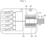
- Fig. 1 is a schematic diagram of the inhaler device according to the configuration example.
- an inhaler device 100 according to the present configuration example includes a power supply 111, a sensor 112, a notifier 113, a memory 114, a communicator 115, a controller 116, a heater 121, , a container 140, and a heat insulator 144.
- the power supply 111 stores electric power.
- the power supply 111 supplies electric power to the structural elements of the inhaler device 100 under the control of the controller 116.
- the power supply 111 may be a rechargeable battery such as a lithium ion secondary battery.
- the sensor 112 acquires various items of information regarding the inhaler device 100.
- the sensor 112 may be a pressure sensor such as a condenser microphone, a flow sensor, or a temperature sensor, and acquire a value generated in accordance with the user's inhalation.
- the sensor 112 may be an input device that receives information input by the user, such as a button or a switch.
- the notifier 113 provides information to the user.
- the notifier 113 may be a light-emitting device that emits light, a display device that displays an image, a sound output device that outputs sound, or a vibration device that vibrates.
- the memory 114 stores various items of information for operation of the inhaler device 100.
- the memory 114 may be a non-volatile storage medium such as flash memory.
- the communicator 115 is a communication interface capable of communication in conformity with any wired or wireless communication standard.
- a communication standard may be, for example, Wi-Fi (registered trademark), Bluetooth (registered trademark), Bluetooth Low Energy (BLE) (registered trademark), near-field communication (NFC), or a standard using a low power wide area (LPWA).
- the controller 116 functions as an arithmetic processing unit and a control circuit, and controls the overall operations of the inhaler device 100 in accordance with various programs.
- the controller 116 includes an electronic circuit such as a central processing unit (CPU) or a microprocessor, for example.
- the container 140 has an internal space 141, and holds a stick substrate 150 in a manner partially accommodated in the internal space 141.
- the container 140 has an opening 142 that allows the internal space 141 to communicate with outside.
- the container 140 accommodates the stick substrate 150 that is inserted into the internal space 141 through the opening 142.
- the container 140 may be a tubular body having the opening 142 and a bottom 143 on its ends, and may define the pillar-shaped internal space 141.
- the container 140 connects with an airflow path that supplies air to the internal space 141.
- a side surface of the inhaler device 100 has an air inlet hole that is an inlet of air into the airflow path.
- the bottom 143 has an air outlet hole that is an outlet of the air from the airflow path to the internal space 141.
- the stick substrate 150 includes a substrate 151 and an inhalation port 152.
- the substrate 151 includes an aerosol source.
- the aerosol source includes a flavor component that is either derived from tobacco or not derived from tobacco.
- the aerosol source may include a medicine.
- the aerosol source may be a liquid including the flavor component that is either derived from tobacco or not derived from tobacco, such as polyhydric alcohol or water. Examples of the polyhydric alcohol include glycerine and propylene glycol.
- the aerosol source may be a solid including the flavor component that is either derived from tobacco or not derived from tobacco.
- the stick substrate 150 held by the container 140 includes the substrate 151 at least partially accommodated in the internal space 141 and the inhalation port 152 at least partially protruding from the opening 142.
- the inhalation port 152 protruding from the opening 142 in his/her mouth, air flows into the internal space 141 through the airflow path (not illustrated), and the air and an aerosol generated from the substrate 151 reach inside the mouth of the user.
- the heater 121 heats the aerosol source to atomize the aerosol source and generate the aerosol.
- the heater 121 has a film-like shape and surrounds the outer circumference of the container 140. Subsequently, heat produced from the heater 121 heats the substrate 151 of the stick substrate 150 from the outer circumference, generating the aerosol.
- the heater 121 produces heat when receiving electric power from the power supply 111.
- the electric power may be supplied in response to the sensor 112 detecting a start of the user's inhalation and/or an input of predetermined information. Subsequently, the supply of the electric power may be stopped in response to the sensor 112 detecting an end of the user's inhalation and/or an input of predetermined information.
- the heat insulator 144 prevents heat from transferring from the heater 121 to the other structural elements.
- the heat insulator 144 may be a vacuum heat insulator or an aerogel heat insulator.
- the configuration example of the inhaler device 100 has been described above.
- the inhaler device 100 is not limited to the above configuration, and may be configured in various ways as exemplified below.
- the heater 121 may have a blade-like shape, and may be disposed so that the heater 121 protrudes from the bottom 143 of the container 140 toward the internal space 141. In this case, the heater 121 having the blade-like shape is inserted into the substrate 151 of the stick substrate 150 and heats the substrate 151 of the stick substrate 150 from its inside. In another example, the heater 121 may be disposed so that the heater 121 covers the bottom 143 of the container 140. In still another example, the heater 121 may be implemented as a combination of two or more selected from a first heater that covers the outer circumference of the container 140, a second heater having the blade-like shape, and a third heater that covers the bottom 143 of the container 140.
- the container 140 may include an opening/closing mechanism that at least partially opens and closes an outer shell defining the internal space 141.
- the opening/closing mechanism include a hinge.
- the container 140 may accommodate the stick substrate 150 while sandwiching the stick substrate 150 inserted into the internal space 141 by opening and closing the outer shell.
- the heater 121 may be at the sandwiching position of the container 140 and may produce heat while pressing the stick substrate 150.
- means for atomizing the aerosol source is not limited to heating by the heater 121.
- the means for atomizing the aerosol source may be induction heating.
- the inhaler device 100 includes at least an electromagnetic induction source such as a coil that generates a magnetic field instead of the heater 121.
- the inhaler device 100 may be provided with a susceptor that produces heat by the induction heating, or the stick substrate 150 may include the susceptor.
- the inhaler device 100 operates together with the stick substrate 150 to generate the aerosol to be inhaled by the user.
- the controller 116 controls the operation of the heater 121 on the basis of a heating profile.
- the control of the operation of the heater 121 is achieved by controlling the supply of power from the power supply 111 to the heater 121.
- the heater 121 heats the stick substrate 150 (more specifically, the aerosol source included in the stick substrate 150) using the power supplied from the power supply 111.
- the heating profile is control information for controlling heating temperature of the aerosol source.
- the heating profile may be control information for controlling the temperature of the heater 121.
- the heating profile can include a target value of the heating temperature (hereinafter also referred to as a target temperature) of the aerosol source.
- the target temperature may change in accordance with time elapsed since a start of heating, and in this case, the heating profile includes information that defines temporal changes in the target temperature.
- the heating profile can include a parameter that defines a method for supplying power to the heater 121 (hereinafter also referred to as a power supply parameter).
- the power supply parameter includes, for example, a voltage applied to the heater 121, on/off of the supply of power to the heater 121, a feedback control method to be employed, or the like. On/off of the supply of power to the heater 121 may be regarded as on/off of the heater 121.
- the controller 116 controls the operation of the heater 121 such that the temperature (hereinafter also referred as an actual temperature) of the heater 121 changes in the same manner as the target temperature defined in the heating profile.
- the heating profile is typically designed in such a way as to optimize the flavor tasted by the user when the user inhales the aerosol generated from the stick substrate 150. By controlling the operation of the heater 121 on the basis of the heating profile, therefore, the flavor tasted by the user can be optimized.
- the control of the temperature of the heater 121 can be achieved through, for example, known feedback control.
- the feedback control may be, for example, a PID (proportional-integral-differential) controller.
- the controller 116 can supply the power from the power supply 111 to the heater 121 in a form of a pulse based on pulse width modulation (PWM) or pulse frequency modulation (PFM).
- PWM pulse width modulation
- PFM pulse frequency modulation
- the controller 116 can control the temperature of the heater 121 by adjusting a duty ratio of the power pulse in the feedback control.
- the controller 116 may perform simple on/off control in the feedback control.
- the controller 116 may cause the heater 121 to produce heat until the actual temperature reaches the target temperature, cause the heater 121 to stop producing heat when the actual temperature reaches the target temperature, and case the heater 121 to resume the heating when the actual temperature falls below the target temperature.
- the temperature of the heater 121 can be quantified by measuring or estimating a resistance (more specifically, electrical resistance) of the heater 121 (more specifically, a resistance heater constituting the heater 121). This is because the resistance of the resistance heater changes in accordance with the temperature.
- the resistance of the resistance heater can be estimated by measuring a decrease in voltage of the resistance heater. The decrease in the voltage of the resistance heater can be measured by a voltage sensor that measures a potential difference applied to the resistance heater.
- the temperature of the heater 121 may be measured by a thermistor provided near the heater 121.
- a thermistor is a resistor whose resistance changes in accordance with temperature.
- a period of time from a start to an end of a process for generating the aerosol using the stick substrate 150 will be referred to as a heating session hereinafter.
- a heating session is a period of time in which the operation of the heater 121 is controlled on the basis of a heating profile.
- a start of a heating session is a time when heating based on a heating profile starts.
- An end of a heating session is a time when a sufficient amount of aerosol is no longer generated.
- a heating session includes a preheating period and a puffable period following the preheating period.
- the puffable period is a period when a sufficient amount of aerosol is assumed to be generated.
- the preheating period is a period from a start of heating until the puffable period starts. Heating performed in the preheating period will also be referred to as preheating.
- Table 1 shows an example of the heating profile.
- Table 1 Example of heating profile Period Temporal changes in target temperature Temporal changes in power supply parameter Section Duration STEP 0 - Increase to 300°C (no time control) ON STEP 1 10 sec. Maintain at 300°C ON STEP 2 - Decrease to 220°C (no time control) OFF STEP 3 - Increase to 230°C (no time control) ON STEP 4 60 sec. Maintain at 230°C ON STEP 5 60 sec. Increase to 260°C ON STEP 6 60 sec. Maintain at 260°C ON STEP 7 5 sec. - OFF
- the heating profile may be divided into a plurality of periods, and a temporal change in the target temperature and a temporal change in the power supply parameter may be specified for each period.
- the heating profile is divided into a total of eight periods of STEP 0 to STEP 7.
- a temporal change in the target temperature and a temporal change in the power supply parameter are specified.
- the steps specified in the heating profile are examples of a unit period in the present embodiment.
- time control might be performed.
- the time control is control for ending the step when a predetermined period of time (that is, duration set for each step) elapses.
- a rate of change in the temperature of the heater 121 may be controlled such that the temperature of the heater 121 reaches the target temperature at an end of the duration.
- the temperature of the heater 121 may be controlled such that the temperature of the heater 121 reaches the target temperature halfway through the duration and remains at the target temperature until the end of the duration.
- the time control is performed in STEP 1 and STEP 4 to STEP 7.
- a period in which the time control is performed will also be referred to as a time-fixed period hereinafter.
- the time control might not be performed.
- the step ends when the temperature of the heater 121 reaches a predetermined temperature (that is, the target temperature set for each step).
- the duration of a step in which the time control is not performed therefore, changes in accordance with a rate of change in temperature.
- the time control is not performed in STEPs 0, 2, and 3.
- a period in which the time control is not performed will also be referred to as a time-variable period hereinafter.
- Fig. 2 is a graph illustrating an example of changes in the temperature of the heater 121 at a time when the temperature control is performed on the basis of the heating profile shown in Table 1.
- a horizontal axis of a graph 20 represents time (seconds).
- a vertical axis of the graph 20 represents the temperature of the heater 121.
- a line 21 indicates the changes in the temperature of the heater 121.
- the temperature of the heater 121 changes in the same manner as the target temperature specified in the heating profile.
- An example of the heating profile will be described hereinafter with reference to Table 1 and Fig. 2 .
- the temperature of the heater 121 increases to 300°C from an initial temperature.
- the initial temperature is the temperature of the heater 121 at a start of heating.
- the time control is not performed. STEP 0, therefore, ends when the temperature of the heater 121 reaches 300°C.
- STEP 0 ends in 20 seconds.
- the temperature of the heater 121 is maintained at 300°C.
- the preheating period ends as STEP 1 ends, and the puffable period starts as STEP 2 starts.
- the preheating period is short. If the stick substrate 150 is not sufficiently heated, however, moisture that has not been fully evaporated might remain inside the stick substrate 150. If the user puffs in this state, hot steam might be delivered to the inside of the user's mouth. It is therefore desirable for the preheating period to last for a certain length of time. In an example, it is desirable to sharply increase the temperature of the heater 121 to 300°C in STEP 0 and to secure a certain duration of STEP 1.
- the temperature of the heater 121 decreases to 220°C.
- the time control is not performed. STEP 2, therefore, ends when the temperature of the heater 121 reaches 220°C. In the example illustrated in Fig. 2 , STEP 2 ends in 10 seconds.
- the supply of power to the heater 121 is stopped. It is therefore possible to decrease the temperature of the heater 121 as fast as possible. By decreasing the temperature of the heater 121 halfway through the heating session like this, rapid consumption of the aerosol source can be prevented. As a result, it is possible to prevent depletion of the aerosol source during the heating session.
- STEP 3 the temperature of the heater 121 increases to 230°C.
- the time control is not performed. STEP 3, therefore, ends when the temperature of the heater 121 reaches 230°C. In the example illustrated in Fig. 2 , STEP 3 ends in 5 seconds.
- the temperature of the heater 121 is increased to 260°C stepwise.
- the temperature of the heater 121 decreases.
- the supply of power to the heater 121 is stopped.
- the duration is specified, but the target temperature is not specified. STEP 7, therefore, ends at an end of the duration.
- a sufficient amount of aerosol can be generated because of residual heat in the stick substrate 150. In this example, therefore, the puffable period, that is, the heating session, ends as STEP 7 ends.
- the notifier 113 may notify the user of information indicating a timing at which the preheating ends. For example, the notifier 113 notifies of information for informing the user of the end of the preheating before the preheating ends or, after the preheating ends, notifies of information indicating that the preheating has ended.
- the notification for the user can be performed, for example, by turning on an LED (light-emitting diode), performing vibration, or the like. The user can puff immediately after the end of the preheating on the basis of such notification.
- the notifier 113 may notify the user of information indicating a timing at which the puffable period ends. For example, the notifier 113 notifies of information for informing the user of the end of the puffable period before the puffable period ends or, after the puffable period ends, notifies of information indicating that the puffable period has ended.
- the notification for the user can be performed, for example, by turning on the LED, performing vibration, or the like. The user can puff until the puffable period ends on the basis of such notification.
- the above-described heating profile is merely an example, and various other examples are conceivable.
- the number of steps, the duration and the target temperature of each step may be changed appropriately.
- the user sometimes puffs while sequentially attaching and removing a plurality of stick substrates 150 to and from the inhaler device 100 at short intervals and successively heating the stick substrates 150.
- a mode of use is called chain smoking.
- heating is started soon after an end of previous heating, and the temperature of the heater 121 is already high at a start of the heating. If no measures are taken, therefore, the preheating period, or more accurately the time-variable period in the preheating period (for example, STEP 0 in the example shown in Table 1 and Fig. 2 ), can be extremely short.
- the preheating period is extremely short, the puffable period might start without moisture within the stick substrate 150 sufficiently evaporated, which deteriorates a smoke taste immediately after a start of the puffable period.
- the inhaler device 100 takes measures to prevent the preheating period from becoming extremely short. The measures will be described in detail with reference to Fig. 3 .
- Fig. 3 is a block diagram for describing the output control according to the present embodiment.
- the inhaler device 100 includes a first switching element 161, a second switching element 162, and a plurality of DC (direct current)/DC converters 163 (163A to 163C) between the power supply 111 and the heater 121.
- a maximum output of the power supply 111 is 26 W.
- the first switching element 161 is a device that starts and stops the supply of power to the heater 121.
- a MOSFET metal-oxide-semiconductor field-effect transistor
- IGBT insulated gate bipolar transistor
- bipolar transistor or the like can be employed.
- Starting the supply of power to the heater 121 will also be referred to as turning on the first switching element 161.
- Stopping the supply of power to the heater 121 will also be referred to as turning off the first switching element 161.
- the controller 116 may perform PWM control for the supply of power to the heater 121 using the first switching element 161. That is, the controller 116 may control the duty ratio by controlling a period of time for which the first switching element 161 is turned on.
- the controller 116 may perform PFM control for the supply of power to the heater 121 using the first switching element 161. That is, the controller 116 may control the duty ratio by controlling a frequency for turning on the first switching element 161.
- the DC/DC converters 163 are transformers that transform a direct current voltage into another direct current voltage. As illustrated in Fig. 3 , the DC/DC converters 163 are arranged between the power supply 111 and the heater 121. The DC/DC converters 163 transform the voltage applied from the power supply 111 and apply resultant voltages to the heater 121.
- the voltage input to the DC/DC converters 163 will also be referred to as an input voltage, and the voltages output from the DC/DC converters 163 will also be referred to as output voltages.
- the input voltage and the output voltages are typically different from each other, but may be the same.
- the output voltages of the DC/DC converters 163 are applied to the heater 121.
- the output voltages of the DC/DC converters 163A to 163C are different from one another.
- the output voltage of the DC/DC converter 163A is 8 V.
- the output voltage of the DC/DC converter 163B is 7 V.
- the output voltage of the DC/DC converter 163C is 6 V.
- the second switching element 162 switches one DC/DC converter 163 that applies a voltage to the heater 121 between the plurality of DC/DC converters 163. That is, the voltage output from one of the DC/DC converters 163A to 163C connected to the power supply 111 and the heater 121 by the second switching element 162 is applied to the heater 121.
- a MOSFET metal-oxide-semiconductor field-effect transistor
- IGBT insulated gate bipolar transistor
- Bipolar transistor bipolar transistor
- the heater 121 heats the aerosol source included in the stick substrate 150 using power supplied from one of the DC/DC converters 163A to 163C. More specifically, the heater 121 heats the stick substrate 150 using power supplied from the DC/DC converter 163 turned on by the second switching element 162.
- the controller 116 selects one DC/DC converter 163 that applies a voltage to the heater 121 from among the DC/DC converters 163A to 163C on the basis of a predetermined parameter. That is, the controller 116 selects, on the basis of the predetermined parameter, the DC/DC converter 163 to be turned on. The controller 116 may turn on the selected DC/DC converter 163 throughout the heating session. With this configuration, an appropriate voltage can be applied to the heater 121 on the basis of the predetermined parameter to heat the stick substrate 150. As a result, quality of user experience can be further improved.
- the predetermined parameter is a value corresponding to the temperature of the heater 121. More specifically, the predetermined parameter may be resistance of the heater 121 or the temperature of the heater 121 estimated from the resistance of the heater 121.
- the temperature of the heater 121 greatly varies depending on whether chain smoking has been performed and a degree of chain smoking. With this configuration, however, an appropriate voltage based on whether chain smoking has been performed and the degree of chain smoking can be applied to the heater 121 to heat the stick substrate 150. As a result, the quality of user experience can be further improved.
- a high degree of chain smoking that is, chain smoking performed at extremely short intervals, will also be referred to as heavy chain smoking.
- a low degree of chain smoking that is, chain smoking that is not deemed heavy, on the other hand, will also be referred to as light chain smoking.
- the predetermined parameter is obtained when the heater 121 starts heating. That is, the predetermined parameter is a value corresponding to the temperature of the heater 121 at a start of heating.
- the resistance of the heater 121 at a start of heating can be measured by applying a voltage to the heater 121 on a trial basis.
- a thermistor may detect the temperature of the heater 121 at a start of heating. When the temperature of the heater 121 at a start of heating is low, chain smoking has not been performed. When the temperature of the heater 121 at a start of heating is high, chain smoking has been performed. When the temperature of the heater 121 at a start of heating is extremely high, heavy chain smoking has been performed. With this configuration, however, a mode of heating the stick substrate 150 can be changed on the basis of whether chain smoking has been performed and the degree of chain smoking. As a result, the quality of user experience can be further improved.
- the controller 116 turns on a DC/DC converter 163 whose output voltage is lower as the temperature of the heater 121 indicated by the predetermined parameter increases. More specifically, the controller 116 turns on a DC/DC converter 163 whose output voltage is lower as the temperature of the heater 121 at a start of heating increases. When the temperature of the heater 121 at a start of heating is lower than 100°C, for example, the controller 116 may determine that chain smoking has not been performed, and turn on the DC/DC converter 163A, whose output voltage is 8 V.
- the controller 116 may determine that light chain smoking has been performed, and turn on the DC/DC converter 163B, whose output voltage is 7 V.
- the controller 116 may determine that heavy chain smoking has been performed, and turn on the DC/DC converter 163C, whose output voltage is 6 V.
- the controller 116 may control the notifier 113 such that the notifier 113 notifies of information corresponding to a DC/DC converter 163 that has been turned on. More specifically, the controller 116 may control the notifier 113 such that the notifier 113 notifies of different information between when the DC/DC converter 163A has been turned on, when the DC/DC converter 163B has been turned on, and when the DC/DC converter 163C has been turned on.
- the user can be notified of whether chain smoking has been performed and the degree of chain smoking. Furthermore, the user can be alerted that the user is smoking excessively.
- An example of the notification performed by the notifier 113 will be described with reference to Fig. 4 .
- Fig. 4 is a diagram for describing an example of the notification performed by the notifier 113 according to the present embodiment.
- the inhaler device 100 includes LEDs 113A to 113C as the notifier 113.
- the controller 116 may turn on the LED 113A as illustrated in Fig. 4 .
- the controller 116 may turn on the DC/DC converter 163B, on the other hand, the controller 116 may turn on the LED 113A and the LED 113B.
- the controller 116 may turn on the LEDs 113A to 113C.
- Various notification methods are conceivable in addition to the notification of information based on the number of LEDs turned on illustrated in Fig. 4 .
- information corresponding to the DC/DC converter 163 that has been turned on may be notified of on the basis of on/off of the LEDs, a flashing rate, or a color of light.
- the information corresponding to the DC/DC converter 163 that has been turned on may be notified of using vibration, display, sound, or the like along with, or instead of, the emission of light.
- Fig. 5 is a flowchart illustrating an example of a procedure of a process performed by the inhaler device 100 according to the present embodiment.
- the inhaler device 100 receives a user operation for requesting a start of heating (step S102).
- An example of the user operation for requesting a start of heating is pressing of a button provided for the inhaler device 100.
- Another example of the user operation for requesting a start of heating is insertion of the stick substrate 150 into the container 140.
- the inhaler device 100 determines whether the temperature of the heater 121 is lower than 100°C (step S104). For example, the controller 116 obtains the resistance of the heater 121 as the predetermined parameter and estimates the temperature of the heater 121 on the basis of the obtained resistance. The controller 116 then determines whether the estimated temperature of the heater 121 is lower than 100°C.
- step S104 If determining that the temperature of the heater 121 is lower than 100°C (step S104: YES), the inhaler device 100 turns on the DC/DC converter 163A, whose output voltage is 8 V (step S106). The inhaler device 100 then starts the preheating (step S114). In this case, the inhaler device 100 performs the preheating while applying a voltage of 8 V to the heater 121.
- step S104 determines whether the temperature of the heater 121 is lower than 200°C (step S108).
- step S108 If determining that the temperature of the heater 121 is lower than 200°C (step S108: YES), the inhaler device 100 turns on the DC/DC converter 163B, whose output voltage is 7 V (step S110). The inhaler device 100 then starts the preheating (step S114). In this case, the inhaler device 100 performs the preheating while applying a voltage of 7 V to the heater 121.
- step S108 If determining that the temperature of the heater 121 is higher than or equal to 200°C (step S108: NO), the inhaler device 100 turns on the DC/DC converter 163C, whose output voltage is 6 V (step S112). The inhaler device 100 then starts the preheating (step S114). In this case, the inhaler device 100 performs the preheating while applying a voltage of 6 V to the heater 121.
- the predetermined parameter is the value corresponding to the temperature of the heater 121
- the present disclosure is not limited to this example.
- the predetermined parameter may be a value corresponding to time elapsed since an end of heating previously performed by the heater 121, instead.
- the predetermined parameter corresponds to an interval between an end of previous heating and the start of the current heating. That is, it can be said that as the elapsed time indicated by the predetermined parameter becomes shorter, heavier chain smoking is being performed.
- an appropriate voltage based on whether chain smoking has been performed and the degree of chain smoking can be applied to the heater 121 to heat the stick substrate 150. As a result, the quality of user experience can be further improved.
- the controller 116 turns on a DC/DC converter 163 whose output voltage is lower. More specifically, as the time elapsed since the heater 121 ended previous heating until the heater 121 starts current heating becomes shorter, the controller 116 turns on a DC/DC converter 163 whose output voltage is lower. For example, when the time elapsed since the heater 121 ended previous heating until the heater 121 starts current heating is longer than or equal to 60 seconds, the controller 116 may determine that chain smoking has not been performed, and turn on the DC/DC converter 163A, whose output voltage is 8 V.
- the controller 116 may determine that light chain smoking has been performed, and turn on the DC/DC converter 163B, whose output voltage is 7 V
- the controller 116 may determine that heavy chain smoking has been performed, and turn on the DC/DC converter 163C, whose output voltage is 6 V.
- the controller 116 When heating by the heater 121 ends, the controller 116 starts to count the elapsed time. If the elapsed time indicated by the predetermined parameter is longer than or equal to a predetermined threshold, the controller 116 may then turn on the DC/DC converter 163 whose output voltage is the highest among those of the plurality of DC/DC converters 163. Here, the controller 116 may stop counting the elapsed time when the elapsed time reaches the predetermined threshold. If the elapsed time since the heater 121 ended previous heating until the heater 121 starts current heating is longer than or equal to 60 seconds, for example, the controller 116 may turn on the DC/DC converter 163A, whose output voltage is 8 V.
- the controller 116 may count the elapsed time until 60 seconds have elapsed since the heater 121 ended previous heating, and stop counting the elapsed time when 60 seconds have elapsed. This is because the DC/DC converter 163A is constantly turned on after the elapsed time reaches 60 seconds. With this configuration, power consumption of the inhaler device 100 can be suppressed.
- the heater 121 is configured as a resistance heater.
- the resistance of the heater 121 (more specifically, the resistance heater constituting the heater 121) changes as the temperature of the heater 121 changes. In particular, as the temperature of the heater 121 increases, the resistance of the heater 121 increases.
- the voltage applied to the heater 121 is fixed, heating efficiency decreases as the resistance of the heater 121 increases.
- the controller 116 may perform output control of the heater 121.
- the output control of the heater 121 is control for increasing the voltage applied to the heater 121 in unit time as the temperature of the heater 121 increases. More specifically, the controller 116 increases the voltage applied to the heater 121 in unit time in accordance with an increase in the resistance of the heater 121, which accompanies an increase in the temperature of the heater 121. With this configuration, a decrease in the heating efficiency due to an increase in the resistance of the heater 121 can be cancelled by increasing the voltage applied to the heater 121 in unit time. That is, the heating efficiency can be kept high.
- the controller 116 performs the output control in a period in which the temperature of the heater 121 continues to increase after heating by the heater 121 starts. More specifically, the controller 116 performs the output control in the preheating period, or more specifically, in the time-variable period in the preheating period. With this configuration, a desired level of heating efficiency can be maintained in the preheating period, and the length of the preheating period can be optimized. As a result, the preheating period can be shortened, for example, and usability improves.
- the controller 116 performs the output control such that an output of the heater 121 becomes a predetermined target value. More specifically, the controller 116 performs the output control such that the output of the heater 121 calculated on the basis of the resistance of the heater 121 and the voltage applied to the heater 121 becomes the predetermined target value (hereinafter also referred to as an output target).
- an output target the predetermined target value
- the controller 116 may set the output target on the basis of the maximum output of the power supply 111. For example, the controller 116 may set a value substantially equal to the maximum output as the output target by, for example, setting the output target to about 90% of the maximum output of the power supply 111. With this configuration, the heating efficiency of the heater 121 can be maximized.
- the controller 116 may control a timing of performing the output control on the basis of a value corresponding to the temperature of the heater 121.
- the value corresponding to the temperature of the heater 121 may be the temperature of the heater 121 itself or the resistance of the heater 121, which changes as the temperature of the heater 121 changes.
- the controller 116 may perform the output control each time the temperature of the heater 121 increases by 100°C. With this configuration, the output of the heater 121 can reach the output target at an appropriate timing.
- the controller 116 increases, as the output control, a period of time for which power is supplied to the heater 121 in unit time as the temperature of the heater 121 increases. More specifically, the controller 116 may control, as the output control, the first switching element 161 such that a period of time for which power is supplied to the heater 121 in unit time increases as the temperature of the heater 121 increases. For example, the controller 116 increases the duty ratio of the power pulse supplied to the heater 121 as the temperature of the heater 121 increases. With this configuration, a decrease in the heating efficiency due to an increase in the resistance of the heater 121 can be cancelled by increasing the duty ratio of the power pulse. That is, the heating efficiency can be kept high. This point will be described with reference to Fig. 6 .
- Fig. 6 is a graph for describing the output control according to the present modification.
- a graph 30 of Fig. 6 indicates changes in the temperature of the heater 121 in the preheating period.
- a vertical axis of the graph 30 represents the temperature of the heater 121, and the resistance of the heater 121 is also shown.
- a horizontal axis of the graph 30 represents time (seconds).
- the controller 116 sets the duty ratio to 40% in a period until the temperature of the heater 121 reaches 100°C.
- the controller 116 sets the duty ratio to 70% in a period until the temperature of the heater 121 reaches 200°C after reaching 100°C.
- the controller 116 sets the duty ratio to 100% in a period until the temperature of the heater 121 reaches 300°C after reaching 200°C.
- the output "P” of the heater 121 is 25.6 W according to the above Expression (1).
- the output "P” of the heater 121 is 25.6 W according to the above Expression (1).
- the output "P” of the heater 121 is 25.6 W according to the above Expression (1).
- the output "P” of the heater 121 is thus kept at the output target of 25.6 W, which is substantially the same as the maximum output of 26 W of the power supply 111. With this configuration, the preheating period can be shortened. In addition, since the output of the heater 121 becomes constant, the load of the power supply 111 can be reduced.
- the output voltage of the DC/DC converter 163 is 5 V and the duty ratio is constantly kept at 100%.
- the output "P" of the heater 121 is 25 W according to the above Expression (1).
- the output "P" of the heater 121 is 14.2 W according to the above Expression (1).
- the output "P" of the heater 121 is 10 W according to the above Expression (1).
- the output "P" of the heater 121 thus decreases as the temperature of the heater 121 increases, and efficient heating becomes difficult. In the present modification, however, efficient heating can be achieved compared to the comparative example.
- Temperature intervals for performing the output control are not limited to 100°C, and any temperature intervals, such as 10°C or 1°C, may be set, instead.
- changes in the duty ratio can be made closer to linear. As a result, it becomes possible to prevent the output of the heater 121 from deviating from the output target.
- the present disclosure is not limited to this example.
- the controller 116 may control the timing of performing the output control on the basis of time elapsed since a start of heating, instead.
- the controller 116 may perform the output control in cycles of 10 seconds.
- the time intervals of the output control are not limited to 10 seconds, and any time intervals, such as 5 seconds or 1 second, may be set, instead. By reducing the time intervals of the output control, for example, changes in the duty ratio can be made closer to linear. As a result, it becomes possible to prevent the output of the heater 121 from deviating from the output target.
- the inhaler device 100 decreases the voltage applied to the heater 121 as the temperature of the heater 121 at a start of heating increases.
- the voltage applied to the heater 121 is decreased by turning on a DC/DC converter 163 whose output voltage is lower as the temperature of the heater 121 at a start of heating increases.
- the present disclosure is not limited to this example.
- the second modification and the third modification may be combined together. That is, in the output control, the controller 116 may decrease the voltage applied to the heater 121 in unit time on the basis of the predetermined parameter.
- the controller 116 may change the duty ratio from 40% to 70%, and then to 100%, as the temperature increases.
- the controller 116 may change the duty ratio from 30% to 60%, and then to 90%, as the temperature increases.
- the controller 116 may change the duty ratio from 20% to 50%, and then to 80%, as the temperature increases. With this configuration, when chain smoking is performed, it is possible to prevent the preheating period from becoming extremely short, thereby improving the smoke taste. In addition, the load of the power supply 111 becomes constant.
- the present disclosure is not limited to this example. It is sufficient that the controller 116 turn on a DC/DC converter 163 selected on the basis of the predetermined parameter in at least the time-variable period in the preheating period, and thereafter the controller 116 may switch the DC/DC converter 163 to be turned on.
- the predetermined parameter may include parameters relating to an environment such as atmospheric temperature and humidity.
- the controller 116 can turn on an appropriate DC/DC converter 163 in an environment where the inhaler device 100 is used.
- the predetermined parameter may also include a heating profile. In this case, the controller 116 can turn on an appropriate DC/DC converter 163 for a heating profile to be used.
- the inhaler device 100 may include two, or four or more, DC/DC converters 163, instead.
- One DC/DC converter 163 may be capable of outputting a plurality of voltages, and in this case, it is sufficient that the inhaler device 100 include one DC/DC converter 163.
- the voltage applied to the heater 121 in unit time may be regarded as an average of voltages applied to the heater 121.
- the voltage applied to the heater 121 in unit time may be regarded as an effective value of the voltage applied to the heater 121.
- the parameter that is specified in the heating profile and that relates to the heating temperature of the aerosol source is the temperature of the heater 121
- the present disclosure is not limited to this example.
- the parameter relating to the heating temperature of the aerosol source may be the resistance of the heater 121, instead of the temperature of the heater 121 itself described in the above embodiment.
- each device described herein may be achieved by software, hardware, or a combination of software and hardware.
- a program constituting software is stored in advance, for example, in a storage medium (more specifically, a non-transitory computer-readable storage medium) provided inside or outside each device.
- each program When executed by a computer that controls each device described herein, for example, each program is loaded into a RAM and executed by a processing circuit such as CPU.
- the storage medium is, for example, a magnetic disk, an optical disc, a magneto-optical disk, a flash memory, or the like.
- the computer program may be distributed over a network, instead, without using a storage medium.
- the computer may be an integrated circuit for a specific application such as an ASIC, a general-purpose processor that executes a function by reading a software program, a computer on a server used for cloud computing, or the like.
- the process by each device described herein may be performed by a plurality of computers in a distributed manner.
Landscapes
- Engineering & Computer Science (AREA)
- Computer Networks & Wireless Communication (AREA)
- Thermotherapy And Cooling Therapy Devices (AREA)
- Control Of Resistance Heating (AREA)
Applications Claiming Priority (1)
| Application Number | Priority Date | Filing Date | Title |
|---|---|---|---|
| PCT/JP2022/029040 WO2024024004A1 (ja) | 2022-07-28 | 2022-07-28 | エアロゾル生成システム、制御方法、及びプログラム |
Publications (1)
| Publication Number | Publication Date |
|---|---|
| EP4559336A1 true EP4559336A1 (en) | 2025-05-28 |
Family
ID=89705710
Family Applications (1)
| Application Number | Title | Priority Date | Filing Date |
|---|---|---|---|
| EP22953097.7A Pending EP4559336A1 (en) | 2022-07-28 | 2022-07-28 | Aerosol generation system, control method, and program |
Country Status (6)
| Country | Link |
|---|---|
| US (1) | US20250160434A1 (https=) |
| EP (1) | EP4559336A1 (https=) |
| JP (1) | JP7787998B2 (https=) |
| KR (1) | KR20250041147A (https=) |
| CN (1) | CN119630302A (https=) |
| WO (1) | WO2024024004A1 (https=) |
Family Cites Families (4)
| Publication number | Priority date | Publication date | Assignee | Title |
|---|---|---|---|---|
| JP4324439B2 (ja) * | 2003-09-30 | 2009-09-02 | 京セラ株式会社 | セラミックヒータおよびセラミックヒータ構造体 |
| JP4845763B2 (ja) * | 2006-04-10 | 2011-12-28 | キヤノン株式会社 | 吐出機能自己診断方法 |
| CN104571191B (zh) * | 2015-01-22 | 2018-01-02 | 卓尔悦欧洲控股有限公司 | 温控系统及其电子烟 |
| KR102131278B1 (ko) | 2017-09-26 | 2020-07-07 | 주식회사 케이티앤지 | 에어로졸 생성장치의 히터에 공급되는 배터리의 전력을 제어하는 방법 및 그 에어로졸 생성장치 |
-
2022
- 2022-07-28 WO PCT/JP2022/029040 patent/WO2024024004A1/ja not_active Ceased
- 2022-07-28 JP JP2024536662A patent/JP7787998B2/ja active Active
- 2022-07-28 KR KR1020257005810A patent/KR20250041147A/ko active Pending
- 2022-07-28 CN CN202280098575.4A patent/CN119630302A/zh active Pending
- 2022-07-28 EP EP22953097.7A patent/EP4559336A1/en active Pending
-
2025
- 2025-01-23 US US19/035,030 patent/US20250160434A1/en active Pending
Also Published As
| Publication number | Publication date |
|---|---|
| JP7787998B2 (ja) | 2025-12-17 |
| JPWO2024024004A1 (https=) | 2024-02-01 |
| US20250160434A1 (en) | 2025-05-22 |
| KR20250041147A (ko) | 2025-03-25 |
| CN119630302A (zh) | 2025-03-14 |
| WO2024024004A1 (ja) | 2024-02-01 |
Similar Documents
| Publication | Publication Date | Title |
|---|---|---|
| US20240108823A1 (en) | Inhalation device, base material, and control method | |
| JP7614379B2 (ja) | 吸引装置、システム、及び制御方法 | |
| US20240196988A1 (en) | Inhalation device, substrate, and control method | |
| EP4316290A1 (en) | Inhalation device, control method, and program | |
| JP2025175009A (ja) | エアロゾル生成システム、制御方法、及びプログラム | |
| EP4388905A1 (en) | Inhalation device, base material, and control method | |
| EP4316286A1 (en) | Inhalation device, control method, and program | |
| US20250000172A1 (en) | Aerosol generation system, control method, and non-transitory computer readable medium | |
| EP4559336A1 (en) | Aerosol generation system, control method, and program | |
| US20230371602A1 (en) | Inhalation device, base material, control method, and non-transitory computer readable medium | |
| EP4563024A1 (en) | Aerosol generation system, control method, and program | |
| EP4470400A1 (en) | Induction heating system, control method, and program | |
| JP7813379B2 (ja) | エアロゾル生成システム、制御方法及びプログラム | |
| US20240373935A1 (en) | Induction heating system, control method, and non-transitory computer readable medium | |
| EP4702859A1 (en) | Aerosol generation system | |
| EP4674295A1 (en) | Aerosol generation system, control method, and non-transitory storage medium | |
| EP4427615A1 (en) | Aerosol generation system, control method, and program | |
| WO2024171266A1 (ja) | エアロゾル生成装置の電源ユニット、及び、エアロゾル生成装置 | |
| WO2026018403A1 (ja) | 吸引装置および方法 | |
| WO2026018404A1 (ja) | 吸引装置および方法 | |
| KR20250121383A (ko) | 흡인 장치용 전력 공급 유닛, 제어 방법, 및 제어 프로그램 |
Legal Events
| Date | Code | Title | Description |
|---|---|---|---|
| STAA | Information on the status of an ep patent application or granted ep patent |
Free format text: STATUS: THE INTERNATIONAL PUBLICATION HAS BEEN MADE |
|
| PUAI | Public reference made under article 153(3) epc to a published international application that has entered the european phase |
Free format text: ORIGINAL CODE: 0009012 |
|
| STAA | Information on the status of an ep patent application or granted ep patent |
Free format text: STATUS: REQUEST FOR EXAMINATION WAS MADE |
|
| 17P | Request for examination filed |
Effective date: 20250224 |
|
| AK | Designated contracting states |
Kind code of ref document: A1 Designated state(s): AL AT BE BG CH CY CZ DE DK EE ES FI FR GB GR HR HU IE IS IT LI LT LU LV MC MK MT NL NO PL PT RO RS SE SI SK SM TR |
|
| DAV | Request for validation of the european patent (deleted) | ||
| DAX | Request for extension of the european patent (deleted) |