EP4557586A1 - Cooling liquid flow channel structure in rotating machine - Google Patents
Cooling liquid flow channel structure in rotating machine Download PDFInfo
- Publication number
- EP4557586A1 EP4557586A1 EP23839636.0A EP23839636A EP4557586A1 EP 4557586 A1 EP4557586 A1 EP 4557586A1 EP 23839636 A EP23839636 A EP 23839636A EP 4557586 A1 EP4557586 A1 EP 4557586A1
- Authority
- EP
- European Patent Office
- Prior art keywords
- flow passage
- coolant
- portions
- outer circumferential
- circumferential wall
- Prior art date
- Legal status (The legal status is an assumption and is not a legal conclusion. Google has not performed a legal analysis and makes no representation as to the accuracy of the status listed.)
- Pending
Links
Images

Classifications
-
- H—ELECTRICITY
- H02—GENERATION; CONVERSION OR DISTRIBUTION OF ELECTRIC POWER
- H02K—DYNAMO-ELECTRIC MACHINES
- H02K5/00—Casings; Enclosures; Supports
- H02K5/04—Casings or enclosures characterised by the shape, form or construction thereof
- H02K5/20—Casings or enclosures characterised by the shape, form or construction thereof with channels or ducts for flow of cooling medium
- H02K5/203—Casings or enclosures characterised by the shape, form or construction thereof with channels or ducts for flow of cooling medium specially adapted for liquids, e.g. cooling jackets
-
- H—ELECTRICITY
- H02—GENERATION; CONVERSION OR DISTRIBUTION OF ELECTRIC POWER
- H02K—DYNAMO-ELECTRIC MACHINES
- H02K9/00—Arrangements for cooling or ventilating
- H02K9/19—Arrangements for cooling or ventilating for machines with closed casing and closed-circuit cooling using a liquid cooling medium, e.g. oil
Definitions
- the present invention is applied to various rotating machines such as a motor and a generator for driving an electric vehicle, and relates to a coolant flow passage structure for cooling the rotating machine.
- a flow passage structure that is applied to a motor and includes a cooling water passage through which cooling water flows on an outer circumferential surface of the motor
- a flow passage structure described in Patent Literature 1 for example, a flow passage structure described in Patent Literature 1 is known.
- the motor has a cylindrical frame constituting an outer circumferential wall thereof, and a water jacket having a cooling water passage is provided so as to cover an outer circumferential surface of the frame.
- the water jacket includes a cylindrical outer circumferential wall having an inner diameter larger than the outer diameter of the frame of the motor, and a plurality of fins disposed between the outer circumferential wall and the frame of the motor, extending by a predetermined length along the axial direction of the motor, and protruding in the radial direction of the motor.
- These fins are arranged in a state of being at predetermined intervals in the circumferential direction of the frame, and in a state in which one end portions in the length direction are alternately close to one side and the other side in the axial direction of the motor. Accordingly, a cooling water passage extending while meandering along the circumferential direction of the frame is formed on the outer circumferential surface side of the frame of the motor.
- the water jacket is provided with a cooling water inlet and a cooling water outlet in a state of being adjacent to each other in the circumferential direction of the water jacket at an end portion on one side in the axial direction of the motor. Furthermore, the water jacket is provided with partition walls which are formed between the cooling water inlet and the cooling water outlet in substantially the same manner as the fins, extend over the entire motor in the axial direction, and partition the cooling water inlet side and the cooling water outlet side.
- the cooling water when the cooling water is fed to the cooling water inlet by a pump or the like, the cooling water flows while meandering along the cooling water passage, that is, along the circumferential direction of the frame on the outer peripheral surface of the frame of the motor. Then, the cooling water is discharged from the cooling water outlet to the outside after circulating almost once around the outer circumferential surface of the frame.
- the cooling water since the cooling water flows on the outer circumferential surface of the frame of the motor, heat generation accompanying the rotation of the motor is suppressed by heat exchange with the cooling water, and the motor is efficiently cooled as compared with the air-cooling type.
- Patent Literature 1 JP S60-153653 U ( Fig. 2 )
- the motor including the cooling water passage has a configuration in which the cooling water passage extends while meandering along the circumferential direction of the frame.
- a portion having a large flow passage area that is a cross section and a portion having a small flow passage area are mixed in the cooling water passage. That is, in the cooling water passage, the flow passage area is not uniform, and the flow passage area is large or small. Therefore, the flow passage area of the cooling water passage changes many times before the cooling water flows from the cooling water inlet to the cooling water outlet, and at that time, a pressure loss is likely to occur in the cooling water flowing through the cooling water passage. When such a pressure loss increases, the smooth flow of the cooling water is inhibited, and as a result, the cooling efficiency of the motor decreases.
- the present invention has been made to solve the above problems, and has an object to provide a coolant flow passage structure in a rotating machine capable of reducing a pressure loss of a coolant flowing through a flow passage, thereby securing a smooth flow of the coolant and improving cooling efficiency.
- an invention according to claim 1 is a coolant flow passage structure in a rotating machine provided on a cylindrical outer circumferential wall in a rotating machine and cooling the rotating machine, the coolant flow passage structure in a rotating machine including: a flow passage main body provided in a thick wall portion of the outer circumferential wall so as to extend while meandering along a circumferential direction of the outer circumferential wall, the flow passage main body through which a coolant flows during cooling; and a bypass flow passage extending along a circumferential direction of the outer circumferential wall at one of both end portions in an axial direction of the outer circumferential wall, the bypass flow passage being provided so as to communicate portions with each other on identical end portion side of the outer circumferential wall in the flow passage main body, the bypass flow passage through which a coolant flows during cooling.
- the flow passage main body includes: a plurality of straight flow passage portions which extend along an axial direction of the outer circumferential wall and are disposed at predetermined intervals in a circumferential direction of the outer circumferential wall, and through which a coolant is allowed to linearly flow, and a plurality of reverse flow passage portions that is alternately connected to end portions on an identical side of the straight flow passage portions adjacent to each other on both end portion sides of the outer circumferential wall in a circumferential direction of the outer circumferential wall and reverses a direction in which a coolant flows.
- a flow passage main body extending while meandering along the circumferential direction of the outer circumferential wall is provided.
- the plurality of straight flow passage portions and the plurality of reverse flow passage portions constitute a flow passage main body extending while meandering along the circumferential direction of the outer circumferential wall. Accordingly, the coolant flowing through the flow passage main body during cooling of the rotating machine flows while meandering along the flow passage main body, that is, through the plurality of straight flow passage portions and the plurality of reverse flow passage portions and along the circumferential direction of the outer circumferential wall.
- heat generation accompanying the operation of the rotating machine can be suppressed by heat exchange with the coolant, and the rotating machine can be efficiently cooled as compared with the air-cooling type.
- the outer circumferential wall of the motor is provided with a bypass flow passage that extends along the circumferential direction of the outer circumferential wall at one of both end portions in the axial direction of the motor and communicates portions with each other on the same end portion side of the outer circumferential wall in the flow passage main body, that is, reverse flow passage portions adjacent to each other with each other in the circumferential direction of the outer circumferential wall.
- a bypass flow passage that extends along the circumferential direction of the outer circumferential wall at one of both end portions in the axial direction of the motor and communicates portions with each other on the same end portion side of the outer circumferential wall in the flow passage main body, that is, reverse flow passage portions adjacent to each other with each other in the circumferential direction of the outer circumferential wall.
- the coolant is allowed to flow also in the bypass flow passage when the coolant flows on the end portion side of the outer circumferential wall in the flow passage main body, whereby the pressure loss of the coolant can be reduced. Accordingly, the pressure loss of the coolant can be reduced as compared with the case where the coolant flows through the flow passage main body without the bypass flow passage as described above, whereby a smooth flow of the coolant can be secured and the cooling efficiency of the rotating machine can be improved.
- the invention according to claim 2 is characterized in that, in the coolant flow passage structure in a rotating machine according to claim 1, the bypass flow passage includes a plurality of bypass flow passage portions that respectively communicate the reverse flow passage portions adjacent to each other with each other in a circumferential direction of the outer circumferential wall.
- the bypass flow passage is configured by the plurality of bypass flow passage portions respectively communicating the reverse flow passage portions adjacent to each other with each other in the circumferential direction of the outer circumferential wall.
- the invention according to claim 3 is characterized in that, in the coolant flow passage structure in a rotating machine according to claim 1, a coolant introduction portion for introducing a coolant and a coolant discharge portion for discharging a coolant are provided in each of the predetermined straight flow passage portions adjacent to each other.
- the coolant when the coolant is sent to the coolant introduction portion, the coolant flows into the straight flow passage portion provided with the coolant introduction portion. Then, with this straight flow passage portion as a starting point, the coolant goes around the outer circumferential wall once while meandering along the flow passage main body, that is, along the circumferential direction of the outer circumferential wall, and is discharged from the coolant discharge portion. As described above, since the coolant flows in the entire circumferential direction of the outer circumferential wall, the entire circumferential direction of the rotating machine can be efficiently cooled.
- the invention according to claim 4 is characterized by, in the coolant flow passage structure in a rotating machine according to claim 3, further including a communication flow passage configured to communicate the reverse flow passage portion connected to an end portion of the straight flow passage portion provided with the coolant introduction portion and the reverse flow passage portion connected to an end portion of the straight flow passage portion provided with the coolant discharge portion.
- the reverse flow passage portion connected to the end portion of the straight flow passage portion provided with the coolant introduction portion and the reverse flow passage portion connected to the end portion of the straight flow passage portion provided with the coolant discharge portion are communicated by the communication flow passage.
- the plurality of reverse flow passage portions on the same end portion side of the outer circumferential wall of the flow passage main body, the plurality of bypass flow passage portions of the bypass flow passage, and the communication flow passage constitute a flow passage continuously extending along the circumferential direction on the entire outer circumferential wall, that is, a flow passage going around the outer circumferential wall once.
- the invention according to claim 5 is characterized in that, in the coolant flow passage structure in a rotating machine according to claim 4, a flow passage area in a cross-section of the communication flow passage is set to be smaller than a flow passage area in a cross-section of each of the plurality of bypass flow passage portions.
- the flow passage area in the cross-section of the communication flow passage is set to be smaller than the flow passage area in the cross-section of each of the bypass flow passage portions, when the coolant flows, it is possible to prevent the coolant from immediately flowing (backflow) from the coolant introduction portion to the coolant discharge portion through the communication flow passage.
- the invention according to claim 6 is characterized in that, in the coolant flow passage structure in a rotating machine according to claim 2, among a plurality of respective reverse flow passage portions disposed at both end portions of the outer circumferential wall, a flow passage area in a cross-section of the reverse flow passage portion to which the bypass flow passage portion is not connected is set to be larger than a flow passage area in a cross-section of the reverse flow passage portion to which the bypass flow passage portion is connected.
- the flow passage area in the cross-section of the reverse flow passage portion that is not connected to the bypass flow passage portion is set to be larger than the flow passage area in the cross-section of the reverse flow passage portion that is connected to the bypass flow passage portion, it is possible to secure a smooth flow of the coolant while reducing the pressure loss of the coolant as the entire flow passage as compared with the case where the flow passage areas of all the reverse flow passage portions are the same.
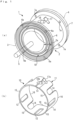
- Fig. 1A shows an appearance of a motor to which a coolant flow passage structure according to an embodiment of the present invention is applied. It should be noted that the motor 1 (rotating machine) is used for, for example, a driving motor of an electric vehicle.
- the motor 1 includes a frame 2 (outer circumferential wall) formed in a cylindrical shape, two brackets 3 and 4 joined to both axial respective end portions of the frame 2, a rotor (not shown) rotatably supported by both the brackets 3 and 4 through a bearing (not shown), a shaft 5 that rotates integrally with the rotor and protrudes forward from the bracket 3, and the like.
- a stator (not shown) is disposed between the frame 2 and the rotor on the inner circumferential surface of the frame 2.
- the frame 2 is manufactured by, for example, aluminum die-casting, and is formed, for the most part, in a cylindrical shape having a predetermined inner diameter, a predetermined outer diameter, and a relatively thick thick wall portion 2a.
- a front flange 6 and a rear flange 7 protruding by a predetermined length in the radial direction are provided at the front end portion and the rear end portion of the frame 2 in the axial direction, respectively.
- a plurality of (only four are shown in Fig. 1A ) mounting holes 6a for bolting the front bracket 3 are formed in the front flange 6.
- a plurality of (only three are shown in Fig. 1A ) mounting holes 7a for bolting the rear bracket 3 are formed also in the rear flange 7.
- a flow passage 10 through which predetermined cooling water (coolant) for cooling the motor 1 flows is formed.
- the flow passage 10 has a predetermined depth (a predetermined thickness in the radial direction of the frame 2), and is formed in the thick wall portion 2a in a state of being opened to the front and the rear of the frame 2. Then, the front bracket 3 and the rear bracket 4 are respectively attached to the front flange 6 and the rear flange 7 of the frame 2 in a watertight state through a ring-shaped seal (not shown), thereby forming the flow passage 10.
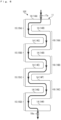
- Fig. 1B three-dimensionally shows the flow passage 10
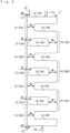
- Fig. 2 shows the flow passage 10 in a state of being developed in the circumferential direction of the frame 2.
- the flow passage 10 includes a flow passage main body 11 that extends while meandering along the circumferential direction of the frame 2, a bypass flow passage 12 that communicates front side reverse flow passage portions 15 and 15 described below adjacent to each other with each other of the flow passage main body 11, and a communication flow passage 13 that communicates a first front side reverse flow passage portion 15A and a fourth front side reverse flow passage portion 15D described below.
- the flow passage main body 11 includes a plurality of straight flow passage portions 14 extending along the axial direction (the left-right direction in Fig. 2 ) of the frame 2 and arranged at predetermined intervals in the circumferential direction (the up-down direction in Fig. 2 ) of the frame 2, a plurality of front side reverse flow passage portions 15 connected to the front end portions of the adjacent straight flow passage portions 14 and 14 and configured to reverse the flow direction of the cooling water, and a plurality of rear side reverse flow passage portions 16 connected to the rear end portions of the adjacent straight flow passage portions 14 and 14 and configured to reverse the flow direction of the cooling water.
- the straight flow passage portion 14 includes eight straight flow passage portions constituted by first to eighth straight flow passage portions 14A to 14H. Any of these first to eighth straight flow passage portions 14A to 14H has a passage width of the same predetermined dimension.
- the front side reverse flow passage portion 15 described above includes four front side reverse flow passage portions constituted by first to fourth front side reverse flow passage portions 15A to 15D respectively connected to front end portions (left end portions in Fig. 2 ) of first and second straight flow passage portions 14A and 14B, front end portions of third and fourth straight flow passage portions 14C and 14D, front end portions of fifth and sixth straight flow passage portions 14E and 14F, and front end portions of seventh and eighth straight flow passage portions 14G and 14H. Any of these first to fourth front side reverse flow passage portions 15A to 15D has a passage width Wa of the same predetermined dimension.
- the rear side reverse flow passage portion 16 described above includes three rear side reverse flow passage portions constituted by first to third rear side reverse flow passage portions 16A to 16C respectively connected to rear end portions (right end portions in Fig. 2 ) of second and third straight flow passage portions 14B and 14C, rear end portions of fourth and fifth straight flow passage portions 14D and 14E, and rear end portions of sixth and seventh straight flow passage portions 14F and 14G.
- Any of these first to third rear side reverse flow passage portions 16A to 16C has the same passage width Wb of a predetermined dimension, and the passage width Wb is set to be larger than the passage width Wa of the first to fourth front side reverse flow passage portions 15A to 15D described above. Therefore, the flow passage area in the cross-section of the rear side reverse flow passage portion 16 is larger than the flow passage area of the front side reverse flow passage portion 15.
- the bypass flow passage 12 extends along the circumferential direction of the frame 2 and is provided so as to communicate the front side reverse flow passage portions 15 and 15 adjacent to each other with each other.
- the bypass flow passage 12 includes three bypass flow passage portions constituted by first to third bypass flow passage portions 12A to 12C that respectively communicate the first and second front side reverse flow passage portions 15A and 15B with each other, the second and third front side reverse flow passage portions 15B and 15C with each other, and the third and fourth front side reverse flow passage portions 15C and 15D with each other. Any of these first to third bypass flow passage portions 12A to 12D has a passage width Wc of the same predetermined dimension.
- the communication flow passage 13 communicates the first front side reverse flow passage portion 15A and the front side reverse flow passage portion 15D with each other.
- the communication flow passage 13 has a passage width Wd of a predetermined dimension, and the passage width Wd is set to be smaller than the passage width Wc of the first to third bypass flow passage portions 12A to 12C described above. Therefore, the flow passage area in the cross-section of the communication flow passage 13 is smaller than the flow passage areas of the first to third bypass flow passage portions 12A to 12C.
- the frame 2 including the flow passage 10 configured as described above is provided with a cooling water introduction portion 17 for introducing cooling water into the flow passage 10 and a cooling water discharge portion 18 for discharging cooling water from the flow passage 10.
- a cooling water introduction portion 17 and cooling water discharge portion 18 is formed in a substantially cylindrical shape, and the introduction flow passage portion 17a inside the cooling water introduction portion 17 is connected to a predetermined position of the first straight flow passage portion 14A of the flow passage main body 11, and the discharge flow passage portion 18a inside the cooling water discharge portion 18 is connected to a predetermined position of the eighth straight flow passage portion 14H of the flow passage main body 11.
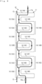
- Fig. 3 shows a flow of cooling water in the flow passage 10.
- the cooling water is sent to the cooling water introduction portion 17 by a pump (not shown) in order to cool the motor 1 in operation
- the cooling water flows into the first straight flow passage portion 14A of the flow passage main body 11 through the introduction flow passage portion 17a in the cooling water introduction portion 17.
- the cooling water flows along the flow passage main body 11 as indicated by a thick arrow in Fig. 3 . That is, the cooling water flowing into the flow passage main body 11 flows while meandering along the circumferential direction of the frame 2.
- the cooling water having reached the eighth straight flow passage portion 14H is discharged to the outside through the discharge flow passage portion 18a in the cooling water discharge portion 18.
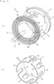
- Fig. 4A shows an appearance of the motor 1C
- Fig. 4B shows a flow passage 10C formed in the frame 2 of the motor 1C
- Fig. 5 shows the flow passage 10C in a state of being developed in the circumferential direction of the frame 2.
- the flow passage 10C provided in the frame 2 of the motor 1C has only the flow passage main body 11 and does not have the bypass flow passage 12 and the communication flow passage 13 with respect to the flow passage 10 of the present embodiment. Therefore, when the cooling water is sent to the flow passage 10C, the cooling water flows only along the flow passage main body 11 which meanders along the circumferential direction of the frame 2 as shown in Fig. 6 .
- the cooling water flows through the bypass flow passage 12 having the first to third bypass flow passage portions 12A to 12C and the communication flow passage 13, in addition to the flow passage main body 11 of the flow passage 10.
- the pressure loss of the cooling water flowing through the flow passage 10 can be reduced as compared with the flow passage 10C of the comparative example. It should be noted that although detailed data is omitted, as a result of analysis of a simulation in which cooling water flows in the flow passage 10 of the present embodiment and the flow passage 10C of the comparative example, it has been confirmed that the flow velocity of the cooling water flowing through the first to third front side reverse flow passage portions 15A to 15C of the flow passage 10 connected through the first to third bypass flow passage portions 12A to 12C rises more than that of the flow passage 10C (that is, the pressure loss of the flow passage 10 is reduced as compared with that of the flow passage 10C). Therefore, according to the present embodiment, since the pressure loss of the cooling water can be reduced, a smooth flow of the cooling water can be secured, and the cooling efficiency of the motor 1 can be improved.
- the flow passage area in the cross-section of the communication flow passage 13 is set to be smaller than the flow passage area of the bypass flow passage 12 (the first to third bypass flow passage portions 12A to 12C), when the cooling water flows, it is possible to prevent the cooling water from immediately flowing (backflow) from the cooling water introduction portion 17 to the cooling water discharge portion 18 through the communication flow passage 13.
- the flow passage area in the cross-section of the rear side reverse flow passage portion 16 is set to be larger than the flow passage area of the front side reverse flow passage portion 15, it is possible to secure a smooth flow of the cooling water while reducing the pressure loss of the cooling water as the entire flow passage 10 as compared with the case where the flow passage areas of all the reverse flow passage portions 15 and 16 are the same.
- bypass flow passage 12 and the communication flow passage 13 are provided on the front end portion side of the frame 2 in the motor 1, but the present invention is not limited thereto.
- the bypass flow passage 12 and the communication flow passage 13 may be provided on the rear end portion side of the frame 2, and the adjacent rear side reverse flow passage portions 16 and 16 may communicate with each other by the bypass flow passage 12.
- the flow passage structure of the cooling water in the motor 1 as the rotating machine has been described, but the present invention can be applied to various rotating machines (for example, a generator and the like) that generate heat by operation.
- the motor 1 is cooled by causing the cooling water to flow in the flow passage 10 of the motor 1, but another appropriate coolant (for example, cooling oil or the like) may be adopted instead of the above cooling water.
- the detailed configurations and the like of the flow passage 10, the flow passage main body 11, the bypass flow passage 12, and the communication flow passage 13 indicated in the embodiment are merely exemplary and can be appropriately changed within the scope of the gist of the present invention.
- three bypass flow passages 12 first to third bypass flow passage portions 12A to 12C
- the bypass flow passages 12 may be disposed to be reduced to one or two places. Even in such a case, it is possible to obtain an effect of reducing the pressure loss of the cooling water as compared with the above-described flow passage 10C not including the bypass flow passage 12 at all.
Landscapes
- Engineering & Computer Science (AREA)
- Power Engineering (AREA)
- Motor Or Generator Cooling System (AREA)
- Motor Or Generator Frames (AREA)
Abstract
Description
- The present invention is applied to various rotating machines such as a motor and a generator for driving an electric vehicle, and relates to a coolant flow passage structure for cooling the rotating machine.
- Conventionally, as a flow passage structure that is applied to a motor and includes a cooling water passage through which cooling water flows on an outer circumferential surface of the motor, for example, a flow passage structure described in
Patent Literature 1 is known. The motor has a cylindrical frame constituting an outer circumferential wall thereof, and a water jacket having a cooling water passage is provided so as to cover an outer circumferential surface of the frame. Specifically, the water jacket includes a cylindrical outer circumferential wall having an inner diameter larger than the outer diameter of the frame of the motor, and a plurality of fins disposed between the outer circumferential wall and the frame of the motor, extending by a predetermined length along the axial direction of the motor, and protruding in the radial direction of the motor. These fins are arranged in a state of being at predetermined intervals in the circumferential direction of the frame, and in a state in which one end portions in the length direction are alternately close to one side and the other side in the axial direction of the motor. Accordingly, a cooling water passage extending while meandering along the circumferential direction of the frame is formed on the outer circumferential surface side of the frame of the motor. - In addition, the water jacket is provided with a cooling water inlet and a cooling water outlet in a state of being adjacent to each other in the circumferential direction of the water jacket at an end portion on one side in the axial direction of the motor. Furthermore, the water jacket is provided with partition walls which are formed between the cooling water inlet and the cooling water outlet in substantially the same manner as the fins, extend over the entire motor in the axial direction, and partition the cooling water inlet side and the cooling water outlet side.
- In the motor having the cooling water passage configured as described above, when the cooling water is fed to the cooling water inlet by a pump or the like, the cooling water flows while meandering along the cooling water passage, that is, along the circumferential direction of the frame on the outer peripheral surface of the frame of the motor. Then, the cooling water is discharged from the cooling water outlet to the outside after circulating almost once around the outer circumferential surface of the frame. As described above, since the cooling water flows on the outer circumferential surface of the frame of the motor, heat generation accompanying the rotation of the motor is suppressed by heat exchange with the cooling water, and the motor is efficiently cooled as compared with the air-cooling type.
- Patent Literature 1:
JP S60-153653 U Fig. 2 ) - The motor including the cooling water passage has a configuration in which the cooling water passage extends while meandering along the circumferential direction of the frame. A portion having a large flow passage area that is a cross section and a portion having a small flow passage area are mixed in the cooling water passage. That is, in the cooling water passage, the flow passage area is not uniform, and the flow passage area is large or small. Therefore, the flow passage area of the cooling water passage changes many times before the cooling water flows from the cooling water inlet to the cooling water outlet, and at that time, a pressure loss is likely to occur in the cooling water flowing through the cooling water passage. When such a pressure loss increases, the smooth flow of the cooling water is inhibited, and as a result, the cooling efficiency of the motor decreases.
- The present invention has been made to solve the above problems, and has an object to provide a coolant flow passage structure in a rotating machine capable of reducing a pressure loss of a coolant flowing through a flow passage, thereby securing a smooth flow of the coolant and improving cooling efficiency.
- In order to achieve the above object, an invention according to
claim 1 is a coolant flow passage structure in a rotating machine provided on a cylindrical outer circumferential wall in a rotating machine and cooling the rotating machine, the coolant flow passage structure in a rotating machine including: a flow passage main body provided in a thick wall portion of the outer circumferential wall so as to extend while meandering along a circumferential direction of the outer circumferential wall, the flow passage main body through which a coolant flows during cooling; and a bypass flow passage extending along a circumferential direction of the outer circumferential wall at one of both end portions in an axial direction of the outer circumferential wall, the bypass flow passage being provided so as to communicate portions with each other on identical end portion side of the outer circumferential wall in the flow passage main body, the bypass flow passage through which a coolant flows during cooling. The flow passage main body includes: a plurality of straight flow passage portions which extend along an axial direction of the outer circumferential wall and are disposed at predetermined intervals in a circumferential direction of the outer circumferential wall, and through which a coolant is allowed to linearly flow, and a plurality of reverse flow passage portions that is alternately connected to end portions on an identical side of the straight flow passage portions adjacent to each other on both end portion sides of the outer circumferential wall in a circumferential direction of the outer circumferential wall and reverses a direction in which a coolant flows. - According to this configuration, in the thick wall portion of the cylindrical outer circumferential wall of the rotating machine, a flow passage main body extending while meandering along the circumferential direction of the outer circumferential wall is provided. Specifically, the plurality of straight flow passage portions and the plurality of reverse flow passage portions constitute a flow passage main body extending while meandering along the circumferential direction of the outer circumferential wall. Accordingly, the coolant flowing through the flow passage main body during cooling of the rotating machine flows while meandering along the flow passage main body, that is, through the plurality of straight flow passage portions and the plurality of reverse flow passage portions and along the circumferential direction of the outer circumferential wall. As a result, heat generation accompanying the operation of the rotating machine can be suppressed by heat exchange with the coolant, and the rotating machine can be efficiently cooled as compared with the air-cooling type.
- In addition, the outer circumferential wall of the motor is provided with a bypass flow passage that extends along the circumferential direction of the outer circumferential wall at one of both end portions in the axial direction of the motor and communicates portions with each other on the same end portion side of the outer circumferential wall in the flow passage main body, that is, reverse flow passage portions adjacent to each other with each other in the circumferential direction of the outer circumferential wall. In the flow passage main body extending while meandering along the circumferential direction of the outer circumferential wall, the pressure loss of the coolant tends to increase due to a large and rapid change in the flow direction of the coolant on the end portion side of the outer circumferential wall. Therefore, in the present invention, by providing the bypass flow passage so as to communicate the reverse flow passage portions with each other which are the portions on the same end portion side of the outer circumferential wall in the flow passage main body, the coolant is allowed to flow also in the bypass flow passage when the coolant flows on the end portion side of the outer circumferential wall in the flow passage main body, whereby the pressure loss of the coolant can be reduced. Accordingly, the pressure loss of the coolant can be reduced as compared with the case where the coolant flows through the flow passage main body without the bypass flow passage as described above, whereby a smooth flow of the coolant can be secured and the cooling efficiency of the rotating machine can be improved.
- The invention according to
claim 2 is characterized in that, in the coolant flow passage structure in a rotating machine according toclaim 1, the bypass flow passage includes a plurality of bypass flow passage portions that respectively communicate the reverse flow passage portions adjacent to each other with each other in a circumferential direction of the outer circumferential wall. - According to this configuration, the bypass flow passage is configured by the plurality of bypass flow passage portions respectively communicating the reverse flow passage portions adjacent to each other with each other in the circumferential direction of the outer circumferential wall. With the flow passage structure including the flow passage main body having the straight flow passage portion and the reverse flow passage portion configured as described above and the bypass flow passage having the plurality of bypass flow passage portions, the function and effect of
claim 1 described above can be more effectively achieved. - The invention according to
claim 3 is characterized in that, in the coolant flow passage structure in a rotating machine according toclaim 1, a coolant introduction portion for introducing a coolant and a coolant discharge portion for discharging a coolant are provided in each of the predetermined straight flow passage portions adjacent to each other. - According to this configuration, when the coolant is sent to the coolant introduction portion, the coolant flows into the straight flow passage portion provided with the coolant introduction portion. Then, with this straight flow passage portion as a starting point, the coolant goes around the outer circumferential wall once while meandering along the flow passage main body, that is, along the circumferential direction of the outer circumferential wall, and is discharged from the coolant discharge portion. As described above, since the coolant flows in the entire circumferential direction of the outer circumferential wall, the entire circumferential direction of the rotating machine can be efficiently cooled.
- The invention according to
claim 4 is characterized by, in the coolant flow passage structure in a rotating machine according toclaim 3, further including a communication flow passage configured to communicate the reverse flow passage portion connected to an end portion of the straight flow passage portion provided with the coolant introduction portion and the reverse flow passage portion connected to an end portion of the straight flow passage portion provided with the coolant discharge portion. - According to this configuration, the reverse flow passage portion connected to the end portion of the straight flow passage portion provided with the coolant introduction portion and the reverse flow passage portion connected to the end portion of the straight flow passage portion provided with the coolant discharge portion are communicated by the communication flow passage. Accordingly, the plurality of reverse flow passage portions on the same end portion side of the outer circumferential wall of the flow passage main body, the plurality of bypass flow passage portions of the bypass flow passage, and the communication flow passage constitute a flow passage continuously extending along the circumferential direction on the entire outer circumferential wall, that is, a flow passage going around the outer circumferential wall once. By providing such a flow passage together with the flow passage main body, the pressure loss of the coolant flowing while meandering along the flow passage main body can be effectively reduced.
- The invention according to
claim 5 is characterized in that, in the coolant flow passage structure in a rotating machine according toclaim 4, a flow passage area in a cross-section of the communication flow passage is set to be smaller than a flow passage area in a cross-section of each of the plurality of bypass flow passage portions. - According to this configuration, since the flow passage area in the cross-section of the communication flow passage is set to be smaller than the flow passage area in the cross-section of each of the bypass flow passage portions, when the coolant flows, it is possible to prevent the coolant from immediately flowing (backflow) from the coolant introduction portion to the coolant discharge portion through the communication flow passage.
- The invention according to
claim 6 is characterized in that, in the coolant flow passage structure in a rotating machine according toclaim 2, among a plurality of respective reverse flow passage portions disposed at both end portions of the outer circumferential wall, a flow passage area in a cross-section of the reverse flow passage portion to which the bypass flow passage portion is not connected is set to be larger than a flow passage area in a cross-section of the reverse flow passage portion to which the bypass flow passage portion is connected. - According to this configuration, since the flow passage area in the cross-section of the reverse flow passage portion that is not connected to the bypass flow passage portion is set to be larger than the flow passage area in the cross-section of the reverse flow passage portion that is connected to the bypass flow passage portion, it is possible to secure a smooth flow of the coolant while reducing the pressure loss of the coolant as the entire flow passage as compared with the case where the flow passage areas of all the reverse flow passage portions are the same.
-
-
Fig. 1A is a view showing a motor to which a coolant flow passage structure according to an embodiment of the present invention is applied, in whichFig. 1A is an external perspective view, andFig. 1B is a perspective view showing a flow passage of cooling water formed in a thick wall portion of a frame. -
Fig. 2 is a view showing a flow passage of cooling water shown inFig. 1B in a state of being developed in a circumferential direction of a frame. -
Fig. 3 is a view for illustrating a flow of cooling water in the flow passage shown inFig. 2 . -
Fig. 4A is a view showing a motor to which a cooling water flow passage structure in which a bypass flow passage and a communication flow passage are omitted is applied as a comparative example to the motor inFig. 1A , in whichFig. 4A is an external perspective view, andFig. 4B is a perspective view showing a flow passage of cooling water formed in a thick wall portion of a frame. -
Fig. 5 is a view showing a flow passage of cooling water shown inFig. 4B in a state of being developed in a circumferential direction of a frame. -
Fig. 6 is a view for illustrating a flow of cooling water in the flow passage shown inFig. 5 . - Hereinafter, preferred embodiments of the present invention will be described in detail with reference to the drawings.
Fig. 1A shows an appearance of a motor to which a coolant flow passage structure according to an embodiment of the present invention is applied. It should be noted that the motor 1 (rotating machine) is used for, for example, a driving motor of an electric vehicle. - As shown in
Fig. 1A , themotor 1 includes a frame 2 (outer circumferential wall) formed in a cylindrical shape, twobrackets frame 2, a rotor (not shown) rotatably supported by both thebrackets shaft 5 that rotates integrally with the rotor and protrudes forward from thebracket 3, and the like. In addition, a stator (not shown) is disposed between theframe 2 and the rotor on the inner circumferential surface of theframe 2. - It should be noted that in the following description, let a side which is a near side in
Fig. 1A and on which theshaft 5 protrudes be a front side, on the other side, let the opposite side be a rear side, and let thebrackets front bracket 3" and a "rear bracket 4". - The
frame 2 is manufactured by, for example, aluminum die-casting, and is formed, for the most part, in a cylindrical shape having a predetermined inner diameter, a predetermined outer diameter, and a relatively thickthick wall portion 2a. In addition, afront flange 6 and arear flange 7 protruding by a predetermined length in the radial direction are provided at the front end portion and the rear end portion of theframe 2 in the axial direction, respectively. A plurality of (only four are shown inFig. 1A ) mountingholes 6a for bolting thefront bracket 3 are formed in thefront flange 6. Similarly, a plurality of (only three are shown inFig. 1A ) mountingholes 7a for bolting therear bracket 3 are formed also in therear flange 7. - In addition, in the
thick wall portion 2a of theframe 2, aflow passage 10 through which predetermined cooling water (coolant) for cooling themotor 1 flows is formed. Theflow passage 10 has a predetermined depth (a predetermined thickness in the radial direction of the frame 2), and is formed in thethick wall portion 2a in a state of being opened to the front and the rear of theframe 2. Then, thefront bracket 3 and therear bracket 4 are respectively attached to thefront flange 6 and therear flange 7 of theframe 2 in a watertight state through a ring-shaped seal (not shown), thereby forming theflow passage 10. -
Fig. 1B three-dimensionally shows theflow passage 10, andFig. 2 shows theflow passage 10 in a state of being developed in the circumferential direction of theframe 2. As shown in both figures, theflow passage 10 includes a flow passagemain body 11 that extends while meandering along the circumferential direction of theframe 2, abypass flow passage 12 that communicates front side reverseflow passage portions main body 11, and acommunication flow passage 13 that communicates a first front side reverseflow passage portion 15A and a fourth front side reverseflow passage portion 15D described below. - As shown in
Figs. 1(b) and2 , the flow passagemain body 11 includes a plurality of straightflow passage portions 14 extending along the axial direction (the left-right direction inFig. 2 ) of theframe 2 and arranged at predetermined intervals in the circumferential direction (the up-down direction inFig. 2 ) of theframe 2, a plurality of front side reverseflow passage portions 15 connected to the front end portions of the adjacent straightflow passage portions flow passage portions 16 connected to the rear end portions of the adjacent straightflow passage portions - Specifically, as shown in
Fig. 2 , the straightflow passage portion 14 includes eight straight flow passage portions constituted by first to eighth straightflow passage portions 14A to 14H. Any of these first to eighth straightflow passage portions 14A to 14H has a passage width of the same predetermined dimension. - In addition, the front side reverse
flow passage portion 15 described above includes four front side reverse flow passage portions constituted by first to fourth front side reverseflow passage portions 15A to 15D respectively connected to front end portions (left end portions inFig. 2 ) of first and second straightflow passage portions flow passage portions flow passage portions flow passage portions flow passage portions 15A to 15D has a passage width Wa of the same predetermined dimension. - Furthermore, the rear side reverse
flow passage portion 16 described above includes three rear side reverse flow passage portions constituted by first to third rear side reverseflow passage portions 16A to 16C respectively connected to rear end portions (right end portions inFig. 2 ) of second and third straightflow passage portions flow passage portions flow passage portions flow passage portions 16A to 16C has the same passage width Wb of a predetermined dimension, and the passage width Wb is set to be larger than the passage width Wa of the first to fourth front side reverseflow passage portions 15A to 15D described above. Therefore, the flow passage area in the cross-section of the rear side reverseflow passage portion 16 is larger than the flow passage area of the front side reverseflow passage portion 15. - The
bypass flow passage 12 extends along the circumferential direction of theframe 2 and is provided so as to communicate the front side reverseflow passage portions Fig. 2 , thebypass flow passage 12 includes three bypass flow passage portions constituted by first to third bypassflow passage portions 12A to 12C that respectively communicate the first and second front side reverseflow passage portions flow passage portions 15B and 15C with each other, and the third and fourth front side reverseflow passage portions 15C and 15D with each other. Any of these first to third bypassflow passage portions 12A to 12D has a passage width Wc of the same predetermined dimension. - As described above, the
communication flow passage 13 communicates the first front side reverseflow passage portion 15A and the front side reverseflow passage portion 15D with each other. Thecommunication flow passage 13 has a passage width Wd of a predetermined dimension, and the passage width Wd is set to be smaller than the passage width Wc of the first to third bypassflow passage portions 12A to 12C described above. Therefore, the flow passage area in the cross-section of thecommunication flow passage 13 is smaller than the flow passage areas of the first to third bypassflow passage portions 12A to 12C. - As shown in
Fig. 1A , theframe 2 including theflow passage 10 configured as described above is provided with a coolingwater introduction portion 17 for introducing cooling water into theflow passage 10 and a coolingwater discharge portion 18 for discharging cooling water from theflow passage 10. Any of these coolingwater introduction portion 17 and coolingwater discharge portion 18 is formed in a substantially cylindrical shape, and the introductionflow passage portion 17a inside the coolingwater introduction portion 17 is connected to a predetermined position of the first straightflow passage portion 14A of the flow passagemain body 11, and the dischargeflow passage portion 18a inside the coolingwater discharge portion 18 is connected to a predetermined position of the eighth straightflow passage portion 14H of the flow passagemain body 11. -
Fig. 3 shows a flow of cooling water in theflow passage 10. When the cooling water is sent to the coolingwater introduction portion 17 by a pump (not shown) in order to cool themotor 1 in operation, the cooling water flows into the first straightflow passage portion 14A of the flow passagemain body 11 through the introductionflow passage portion 17a in the coolingwater introduction portion 17. The cooling water flows along the flow passagemain body 11 as indicated by a thick arrow inFig. 3 . That is, the cooling water flowing into the flow passagemain body 11 flows while meandering along the circumferential direction of theframe 2. Then, the cooling water having reached the eighth straightflow passage portion 14H is discharged to the outside through the dischargeflow passage portion 18a in the coolingwater discharge portion 18. - In addition, as described above, when the cooling water flows through the flow passage
main body 11, as indicated by a thin arrow inFig. 3 , a part of the cooling water flowing through the first to third front side reverseflow passage portions 15A to 15C respectively flow through the first to third bypassflow passage portions 12A to 12C to the immediately downstream front side reverseflow passage portion 15. - Furthermore, substantially similarly to the first to third bypass
flow passage portions 12A to 12C, in thecommunication flow passage 13, a part of the cooling water flowing through the fourth front side reverseflow passage portion 15D flows to the first front side reverseflow passage portion 15A through thecommunication flow passage 13. - Here, as a comparative example to the above-described
motor 1, with reference toFigs. 4 to 6 respectively corresponding toFigs. 1 to 3 described above, a flow passage structure of cooling water in amotor 1C including aflow passage 10C in which abypass flow passage 12 and acommunication flow passage 13 are omitted from theflow passage 10 of the present embodiment will be briefly described. It should be noted that in the following description, let the same components as those of themotor 1 and theflow passage 10 be denoted by the same reference numerals. -
Fig. 4A shows an appearance of themotor 1C, andFig. 4B shows aflow passage 10C formed in theframe 2 of themotor 1C. In addition,Fig. 5 shows theflow passage 10C in a state of being developed in the circumferential direction of theframe 2. As shown inFigs. 4 and5 , theflow passage 10C provided in theframe 2 of themotor 1C has only the flow passagemain body 11 and does not have thebypass flow passage 12 and thecommunication flow passage 13 with respect to theflow passage 10 of the present embodiment. Therefore, when the cooling water is sent to theflow passage 10C, the cooling water flows only along the flow passagemain body 11 which meanders along the circumferential direction of theframe 2 as shown inFig. 6 . - On the other hand, in the
flow passage 10 of the present embodiment, at the time of cooling themotor 1, as shown inFig. 3 described above, the cooling water flows through thebypass flow passage 12 having the first to third bypassflow passage portions 12A to 12C and thecommunication flow passage 13, in addition to the flow passagemain body 11 of theflow passage 10. - Accordingly, according to the present embodiment, the pressure loss of the cooling water flowing through the
flow passage 10 can be reduced as compared with theflow passage 10C of the comparative example. It should be noted that although detailed data is omitted, as a result of analysis of a simulation in which cooling water flows in theflow passage 10 of the present embodiment and theflow passage 10C of the comparative example, it has been confirmed that the flow velocity of the cooling water flowing through the first to third front side reverseflow passage portions 15A to 15C of theflow passage 10 connected through the first to third bypassflow passage portions 12A to 12C rises more than that of theflow passage 10C (that is, the pressure loss of theflow passage 10 is reduced as compared with that of theflow passage 10C). Therefore, according to the present embodiment, since the pressure loss of the cooling water can be reduced, a smooth flow of the cooling water can be secured, and the cooling efficiency of themotor 1 can be improved. - In addition, in the
flow passage 10 of the present embodiment, since the flow passage area in the cross-section of thecommunication flow passage 13 is set to be smaller than the flow passage area of the bypass flow passage 12 (the first to third bypassflow passage portions 12A to 12C), when the cooling water flows, it is possible to prevent the cooling water from immediately flowing (backflow) from the coolingwater introduction portion 17 to the coolingwater discharge portion 18 through thecommunication flow passage 13. Furthermore, in theflow passage 10, since the flow passage area in the cross-section of the rear side reverseflow passage portion 16 is set to be larger than the flow passage area of the front side reverseflow passage portion 15, it is possible to secure a smooth flow of the cooling water while reducing the pressure loss of the cooling water as theentire flow passage 10 as compared with the case where the flow passage areas of all the reverseflow passage portions - It should be noted that the present invention is not limited to the above-described embodiments, and can be implemented in various modes. For example, in the present embodiment, the
bypass flow passage 12 and thecommunication flow passage 13 are provided on the front end portion side of theframe 2 in themotor 1, but the present invention is not limited thereto. Thebypass flow passage 12 and thecommunication flow passage 13 may be provided on the rear end portion side of theframe 2, and the adjacent rear side reverseflow passage portions bypass flow passage 12. - In addition, in the embodiment, the flow passage structure of the cooling water in the
motor 1 as the rotating machine has been described, but the present invention can be applied to various rotating machines (for example, a generator and the like) that generate heat by operation. Furthermore, in the embodiment, themotor 1 is cooled by causing the cooling water to flow in theflow passage 10 of themotor 1, but another appropriate coolant (for example, cooling oil or the like) may be adopted instead of the above cooling water. - In addition, the detailed configurations and the like of the
flow passage 10, the flow passagemain body 11, thebypass flow passage 12, and thecommunication flow passage 13 indicated in the embodiment are merely exemplary and can be appropriately changed within the scope of the gist of the present invention. For example, in theflow passage 10 of the present embodiment, as shown inFigs. 1(b) and2 , three bypass flow passages 12 (first to third bypassflow passage portions 12A to 12C) are provided at positions facing, in the axial direction, all the rear side reverse flow passage portions 16 (first to third rear side reverseflow passage portions 16A to 16C). However, for manufacturing reasons or the like, thebypass flow passages 12 may be disposed to be reduced to one or two places. Even in such a case, it is possible to obtain an effect of reducing the pressure loss of the cooling water as compared with the above-describedflow passage 10C not including thebypass flow passage 12 at all. -
- 1 motor (rotating machine)
- 1C motor of comparative example
- 2 frame (outer circumferential wall)
- 2a thick wall portion of frame
- 3 front bracket
- 4 rear bracket
- 5 shaft
- 6 front flange
- 6a mounting hole
- 7 rear flange
- 7a mounting hole
- 10 flow passage
- 10C flow passage of comparative example
- 11 flow passage main body
- 12 bypass flow passage
- 12A to 12C first to third bypass flow passage portions
- 13 communication flow passage
- 14 straight flow passage portion
- 14A to 14H first to eighth straight flow path portions
- 15 front side reverse flow passage portion (reverse flow passage portion)
- 15A to 15D first to fourth front side reverse flow passage portions
- 16 rear side reverse flow passage portion (reverse flow passage portion)
- 16A to 16C first to third rear side reverse flow passage portions
- 17 cooling water introduction portion
- 17a introduction flow passage portion
- 18 cooling water discharge portion
- 18a discharge flow passage portion
- Wa passage width of front side reverse flow passage portion
- Wb passage width of rear side reverse flow passage portion
- Wc passage width of bypass flow passage portion
- Wd passage width of communication flow passage
Claims (6)
- A coolant flow passage structure in a rotating machine provided on a cylindrical outer circumferential wall in a rotating machine and cooling the rotating machine, the coolant flow passage structure in a rotating machine comprising:a flow passage main body provided in a thick wall portion of the outer circumferential wall so as to extend while meandering along a circumferential direction of the outer circumferential wall, the flow passage main body through which a coolant flows during cooling; anda bypass flow passage extending along the circumferential direction of the outer circumferential wall at one of both end portions in an axial direction of the outer circumferential wall, the bypass flow passage being provided so as to communicate portions with each other on identical end portion side of the outer circumferential wall in the flow passage main body, the bypass flow passage through which a coolant flows during cooling,wherein the flow passage main body includesa plurality of straight flow passage portions which extends along the axial direction of the outer circumferential wall and is disposed at predetermined intervals in the circumferential direction of the outer circumferential wall, and through which a coolant is allowed to linearly flow, anda plurality of reverse flow passage portions that is alternately connected to end portions on an identical side of the straight flow passage portions adjacent to each other on both end portion sides of the outer circumferential wall in the circumferential direction of the outer circumferential wall and reverses a direction in which a coolant flows.
- The coolant flow passage structure in a rotating machine according to claim 1, wherein the bypass flow passage includes a plurality of bypass flow passage portions that respectively communicate the reverse flow passage portions adjacent to each other with each other in the circumferential direction of the outer circumferential wall.
- The coolant flow passage structure in a rotating machine according to claim 1, wherein a coolant introduction portion for introducing a coolant and a coolant discharge portion for discharging a coolant are provided in each of the predetermined straight flow passage portions adjacent to each other.
- The coolant flow passage structure in a rotating machine according to claim 3, further comprising a communication flow passage configured to communicate the reverse flow passage portion connected to an end portion of the straight flow passage portion provided with the coolant introduction portion and the reverse flow passage portion connected to an end portion of the straight flow passage portion provided with the coolant discharge portion.
- The coolant flow passage structure in a rotating machine according to claim 4, wherein a flow passage area in a cross-section of the communication flow passage is set to be smaller than a flow passage area in a cross-section of each of the plurality of bypass flow passage portions.
- The coolant flow passage structure in a rotating machine according to claim 2, wherein, among a plurality of respective reverse flow passage portions disposed at the both end portions of the outer circumferential wall, a flow passage area in a cross-section of the reverse flow passage portion to which the bypass flow passage portion is not connected is set to be larger than a flow passage area in a cross-section of the reverse flow passage portion to which the bypass flow passage portion is connected.
Applications Claiming Priority (2)
| Application Number | Priority Date | Filing Date | Title |
|---|---|---|---|
| JP2022113545A JP7400888B1 (en) | 2022-07-14 | 2022-07-14 | Coolant flow path structure in rotating machines |
| PCT/JP2023/025608 WO2024014464A1 (en) | 2022-07-14 | 2023-07-11 | Cooling liquid flow channel structure in rotating machine |
Publications (2)
| Publication Number | Publication Date |
|---|---|
| EP4557586A1 true EP4557586A1 (en) | 2025-05-21 |
| EP4557586A4 EP4557586A4 (en) | 2025-12-03 |
Family
ID=89190231
Family Applications (1)
| Application Number | Title | Priority Date | Filing Date |
|---|---|---|---|
| EP23839636.0A Pending EP4557586A4 (en) | 2022-07-14 | 2023-07-11 | COOLANT FLOW CHANNEL STRUCTURE IN A LATHE |
Country Status (5)
| Country | Link |
|---|---|
| US (1) | US12549060B2 (en) |
| EP (1) | EP4557586A4 (en) |
| JP (1) | JP7400888B1 (en) |
| CN (1) | CN119384785B (en) |
| WO (1) | WO2024014464A1 (en) |
Family Cites Families (9)
| Publication number | Priority date | Publication date | Assignee | Title |
|---|---|---|---|---|
| JPS60153653U (en) | 1984-03-22 | 1985-10-14 | 三菱電機株式会社 | Cooling device for rotating electrical machines |
| JP5547783B2 (en) * | 2012-09-27 | 2014-07-16 | 株式会社小松製作所 | Electric motor and its cooling water circuit |
| JP5959687B1 (en) * | 2015-04-28 | 2016-08-02 | 三菱電機株式会社 | Rotating electric machine |
| JP6718842B2 (en) * | 2017-06-22 | 2020-07-08 | 東芝三菱電機産業システム株式会社 | Totally closed fan-shaped rotating electric machine and cooler |
| WO2019187021A1 (en) * | 2018-03-30 | 2019-10-03 | 本田技研工業株式会社 | Cooling structure for rotating electrical device |
| US12132352B2 (en) | 2018-07-19 | 2024-10-29 | Aisin Corporation | Stator cooling structure |
| PL3661027T3 (en) * | 2018-11-29 | 2022-05-02 | Valeo Siemens Eautomotive Germany Gmbh | Stator housing for an electric machine, electric machine for a vehicle and vehicle |
| JP6791463B1 (en) * | 2020-03-30 | 2020-11-25 | 三菱電機株式会社 | Motors and motor devices |
| CN115702542A (en) | 2020-09-18 | 2023-02-14 | 株式会社Ihi | Rotary machine |
-
2022
- 2022-07-14 JP JP2022113545A patent/JP7400888B1/en active Active
-
2023
- 2023-07-11 CN CN202380047624.6A patent/CN119384785B/en active Active
- 2023-07-11 WO PCT/JP2023/025608 patent/WO2024014464A1/en not_active Ceased
- 2023-07-11 US US18/993,491 patent/US12549060B2/en active Active
- 2023-07-11 EP EP23839636.0A patent/EP4557586A4/en active Pending
Also Published As
| Publication number | Publication date |
|---|---|
| WO2024014464A1 (en) | 2024-01-18 |
| EP4557586A4 (en) | 2025-12-03 |
| JP7400888B1 (en) | 2023-12-19 |
| CN119384785B (en) | 2025-06-13 |
| US12549060B2 (en) | 2026-02-10 |
| CN119384785A (en) | 2025-01-28 |
| US20250167624A1 (en) | 2025-05-22 |
| JP2024011513A (en) | 2024-01-25 |
Similar Documents
| Publication | Publication Date | Title |
|---|---|---|
| JP6314158B2 (en) | Rotating electric machine | |
| US8026643B2 (en) | Electrical machine with an internally cooled rotor | |
| EP2602917B1 (en) | Dynamo-electric machine | |
| CN104247229A (en) | Electric machine | |
| JP2013132151A (en) | Rotary electric machine and rotary electric machine cooling system | |
| EP3251880B1 (en) | Electric machine having a tangential architecture with improved air cooling | |
| JP7418940B2 (en) | unit | |
| JP2020058219A (en) | Rotary electric machine | |
| US10205372B2 (en) | Motor-generator shaft with centrifugal fan blades | |
| CN103715787A (en) | Motor having air-cooling structure | |
| US20150015098A1 (en) | Rotor with cooling passage and motor having the same | |
| JPH10234157A (en) | motor | |
| WO2023127410A1 (en) | Drive device | |
| JP2015162936A (en) | Fully closed motor | |
| US12549060B2 (en) | Coolant flow passage structure in rotating machine | |
| JP2016025718A (en) | Motor unit | |
| US10601272B2 (en) | Rotor for an electrical machine, electrical machine, in particular an asynchronous machine for a motor vehicle, and motor vehicle | |
| US12134453B2 (en) | Pod propulsion device | |
| JP7322380B2 (en) | electric oil pump | |
| EP3046792B1 (en) | An electric or hybrid vehicle using motor-generator having shaft with centrifugal fan blades for cooling | |
| JP2007020333A (en) | Liquid-cooled rotary electric machine | |
| US12609579B2 (en) | Rotating electric machine | |
| JP2025070560A (en) | Drive unit | |
| JP2001078391A (en) | Rotating electric machine | |
| CN115133717A (en) | Rotary motor |
Legal Events
| Date | Code | Title | Description |
|---|---|---|---|
| STAA | Information on the status of an ep patent application or granted ep patent |
Free format text: STATUS: THE INTERNATIONAL PUBLICATION HAS BEEN MADE |
|
| PUAI | Public reference made under article 153(3) epc to a published international application that has entered the european phase |
Free format text: ORIGINAL CODE: 0009012 |
|
| STAA | Information on the status of an ep patent application or granted ep patent |
Free format text: STATUS: REQUEST FOR EXAMINATION WAS MADE |
|
| 17P | Request for examination filed |
Effective date: 20250123 |
|
| AK | Designated contracting states |
Kind code of ref document: A1 Designated state(s): AL AT BE BG CH CY CZ DE DK EE ES FI FR GB GR HR HU IE IS IT LI LT LU LV MC ME MK MT NL NO PL PT RO RS SE SI SK SM TR |
|
| DAV | Request for validation of the european patent (deleted) | ||
| DAX | Request for extension of the european patent (deleted) | ||
| A4 | Supplementary search report drawn up and despatched |
Effective date: 20251105 |
|
| RIC1 | Information provided on ipc code assigned before grant |
Ipc: H02K 5/20 20060101AFI20251030BHEP Ipc: H02K 9/19 20060101ALI20251030BHEP |