EP3661027B1 - Stator housing for an electric machine, electric machine for a vehicle and vehicle - Google Patents
Stator housing for an electric machine, electric machine for a vehicle and vehicle Download PDFInfo
- Publication number
- EP3661027B1 EP3661027B1 EP18209098.5A EP18209098A EP3661027B1 EP 3661027 B1 EP3661027 B1 EP 3661027B1 EP 18209098 A EP18209098 A EP 18209098A EP 3661027 B1 EP3661027 B1 EP 3661027B1
- Authority
- EP
- European Patent Office
- Prior art keywords
- channels
- stator housing
- percent
- channel
- electric machine
- Prior art date
- Legal status (The legal status is an assumption and is not a legal conclusion. Google has not performed a legal analysis and makes no representation as to the accuracy of the status listed.)
- Active
Links
- 238000001816 cooling Methods 0.000 claims description 35
- 239000002826 coolant Substances 0.000 claims description 23
- 239000012530 fluid Substances 0.000 claims description 6
- 230000000694 effects Effects 0.000 description 3
- 238000004804 winding Methods 0.000 description 3
- 238000010586 diagram Methods 0.000 description 2
- 239000000463 material Substances 0.000 description 2
- 238000000926 separation method Methods 0.000 description 2
- 238000004519 manufacturing process Methods 0.000 description 1
- 238000007789 sealing Methods 0.000 description 1
- XLYOFNOQVPJJNP-UHFFFAOYSA-N water Substances O XLYOFNOQVPJJNP-UHFFFAOYSA-N 0.000 description 1
Images


Classifications
-
- H—ELECTRICITY
- H02—GENERATION; CONVERSION OR DISTRIBUTION OF ELECTRIC POWER
- H02K—DYNAMO-ELECTRIC MACHINES
- H02K5/00—Casings; Enclosures; Supports
- H02K5/04—Casings or enclosures characterised by the shape, form or construction thereof
- H02K5/20—Casings or enclosures characterised by the shape, form or construction thereof with channels or ducts for flow of cooling medium
- H02K5/203—Casings or enclosures characterised by the shape, form or construction thereof with channels or ducts for flow of cooling medium specially adapted for liquids, e.g. cooling jackets
Definitions
- the present invention refers to a stator housing for an electric machine, comprising a plurality of axially extending main channels, wherein pairs of adjacent main channels are connected by deflection channels to form a meandering cooling path for a coolant.
- the present invention relates to an electric machine for a vehicle and a vehicle.
- DE 10 2016 225 521 A1 discloses a housing for an electric machine with a cooling jacket, which surrounds a central axis annularly.
- the cooling jacket has circumferentially adjacent cooling jacket segments, each of which has a meandering cooling channel.
- the meandering cooling jacket segments are aligned such that respective two adjacent straight sections are configured to guide a coolant in opposite directions, where the straight sections are aligned transversely to a circumferential direction.
- stator housings are disclosed in KR 2017 0011865 A , DE 10 2012 022 451 A1 , TW I 624 137 B , WO 03/100946 A1 , EP 2 369 723 A2 , WO 2009/015946 A1 , WO 2010/118792 A1 and JP 2007 143247 A .
- stator housing with an improved cooling path that is particularly operable with a lower pressure drop.
- the deflection channels may be configured to realize a deflection of the coolant flowing to the cooling path of at least 170°, preferably at least 175°, more preferably at least 179°.
- the main channels extend parallelly in axial direction.
- the cooling channels are arranged at a central axial position pair of adjacent main channels. The central position may be between 40% and 60% of the total length of the pair of adjacent main channels.
- the cooling path comprises an inlet channel connected to a first main channel with respect to the flow direction of the coolant and/or an outlet channel connected to the last main channel with respect to the flow direction of the coolant.
- the inlet channel may be connected to the first main channel by means of a further deflection channel and/or the last main channel may be connection to the outlet channel by means of a further deflection channel.
- a further connection channels may be arranged between the inlet channel and the first main channel and/or a further connection channel may be arranged between the last main channel and outlet channel.
- the inlet channel and/or the outlet channel may be shaped such that it guides the coolant at least partially in a circumferential direction of the stator housing.
- connection channels have a smaller cross-sectional area than the main channels. It has been found out that small connection channels already provide a sufficient equalization between the pressure areas in the adjacent main channels without affecting the cooling efficiency heavily.
- the cross-sectional area of each connection channel may be at least two percent, preferably at least five percent, more preferably at least seven percent, and/or at most thirty percent, preferably at most twenty percent, more preferably at most ten percent, of the cross-sectional area of a main channel connected by the connection channels.
- stator housing according to the invention is configured such that at least two percent, preferably at least five percent, more preferably at least ten percent, and/or at most thirty percent, preferably at most twenty percent, more preferably at most fifteen percent, of a mass flow of the coolant flowing through a main channel is bypassed through the connection channel connecting the main channel with its adjacent main channel.
- connection channels may have various cross-sections such as a circular, oval or rectangular shape.
- connection channels may have a trapezoid cross-section.
- the main channels and the connection channels, and particularly the deflection channels and/or the inlet channel and/or the outlet channel are formed by a cavity in the stator housing.
- the respective cavities may be milled into a material forming the stator housing.
- sections of the cavity forming the main channels may be separated by a wall, wherein each connection channel connecting one of the pairs of adjacent main channels may be formed by a groove in the wall.
- sections of the cavity forming the main channels are deeper than the grooves.
- the stator housing according to the invention may comprise an inner housing element and an outer housing element, wherein the inner housing element is coaxially arranged inside the outer housing element.
- the stator housing may be simply manufactured in a modular manner.
- the cavity may be formed in one of the housing elements.
- the cavity is formed in the inner housing element and closed by the outer housing element.
- the cavity may be formed in the outer housing element and closed by the inner housing element.
- one housing element may comprise a first end shield of the stator housing and one housing element may comprise a second end shield of the stator housing.
- the first end shield is a drive end shield and the second end shield is a non-drive end shield.
- an inlet connected to the inlet cooling path and/or an outlet connected to the outlet cooling path are integrally formed with the outer housing element.
- the inlet and the outlet are arranged at opposing axial positions of the stator housing.
- the vehicle may be a fully electrically driven vehicle or a partially electrically driven vehicle such as a hybrid vehicle.
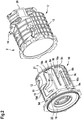
- Fig. 1 is a principle cross-sectional view of an embodiment of an electric machine 1 comprising an embodiment of a stator housing 2, a stator 3 being fixed inside the stator housing 2 by means of a press fit, a rotor 4 being rotatably arranged inside the stator 3 and a shaft 5, which is attached to the rotor 4.
- the rotor 4 comprises multiple permanent magnets 6.
- Fig. 2 is an exploded view of the stator housing 2, which comprises a cooling path 7 including by a plurality of axially extending main channels 8a to 8c and deflection channels 9a, 9b which connect pairs of the adjacent main channels 8a to 8c such that a coolant flowing through the cooling path 7 is deflected by 180°, when leaving a respective main channel 8a to 8c.
- the deflection channels 9a, 9b extend substantially in circumferential direction and are arranged alternatingly on opposing front sides of the stator housing 2.
- the cooling path 7 comprises connection channels 10a, 10b that connect each pair of main channels 8a to 8c in a fluid conductive manner at a central axial position between the deflection channels 9a, 9b.
- the cooling path 7 comprises an inlet channel 11 and an outlet channel 12, which differ from the main channels 8a to 8c in that they extend partially in circumferential direction and that they are configured to guide the coolant from an inlet 13 to the first main channel 8a with respect to a flow direction of the coolant (depicted by an arrow 15) or from a last main channel (not visible in Fig. 2 ) with respect to the flow direction to an outlet 14 of the stator housing 2, respectively.
- the inlet channel 11 and the first main channel 8a are connected by a further deflection channel 9c and the last main channel and the outlet channel 12 by a further deflection channel 9d.
- a further connection channel 10c is provided between the inlet channel 11 and the first main channel 8a and a further connection channel 10d is provided between the last main channel and the outlet channel 12, wherein axial positions of the further connection channels 10c, 10d correspond to those of the connection channels 10a,10b.
- Fig. 3 is a perspective view of the connection channel 10a, which is representative for the other connection channels 10b, 10c, 10d.
- the connection channel 10a has the cross-sectional shape of an isosceles trapezoid, whose long parallel side is about 1.95 times as big as its short parallel side.
- the height of the connection channel 10a is about 60% of the height of the main channel 8a, wherein an angle ⁇ being the inside angle between the long parallel side and a leg of the trapezoid is about 44.7°.
- the cross-sectional area of the connection channel 10a is about 8 % of the cross-sectional area of the main channel 8a that is connected via a connection channel 10a to the main channel 8b. This results in that about 12 % of the mass flow of the coolant flowing through the main channel 8a is bypassed through the connection channel 10a without passing the deflection channel 9a.
- the stator housing comprises an inner housing element 16 and an outer housing element 17.
- the inner housing element 16 is coaxially arranged inside the outer housing element 17.
- the main channels 8a to 8c, the deflection channels 9a to 9d, the connection channels 10a to 10d, the inlet channel 11 and the outlet channel 12 are formed by a cavity milled into a cylindrical structure of the inner housing element 16.
- the pairs of adjacent main channels 8a to 8c are separated by walls 18, wherein the connection channels 10a to 10d are formed by respective grooves in the walls 18.
- the cavity is closed by an inner cylindrical structure of the outer housing element 17.
- the inner housing element 16 comprises a first end shield 19 being a drive end (DE) shield of the electric machine 1 and the outer housing element 17 comprises a second end shield 20 being the non-drive end (NDE) shield of the electric machine. Additionally, on both face sides of the inner housing element 16 sealing 21, 22 are arranged that seal the inner housing element 16 against the outer housing element 17.
- DE drive end
- NDE non-drive end
- Fig. 4 shows stream lines of the coolant flowing along the cooling path 7 during operation of the electric machine 1.
- a flow separation and coolant circulation after having passed a deflection channel is significantly reduced by an equalizing effect of the connection channels.
- Fig. 5 shows a pressure distribution along the cooling path 7 of the stator housing 2 during operation of the electric machine 1 represented by isobars 23a to 23f.
- the coolant enters the cooling path 7 with a maximum pressure drop of exemplarily 3.5 kPa inside a maximum pressure area 23.
- the isobars 23a to 23f denote approximately the following pressure drops: 23a - 3,27 kPa; 23b - 3,03 kPa; 23c - 2,80 kPa; 23d - 2,57 kPa; 23e - 2,33 kPa; 23f - 0,00 kPa.
- Fig. 6 shows a temperature distribution of the inner housing element 16 during operation of the electric machine 1 represented by isotherms.
- hotspot areas 24, 25 there exist local temperature maxima before and behind a respective connection channel 10a to 10d of each main channel 8a to 8c, which are warmer than a single hotspot area in the conventional electric machine without connection channels.
- the absolute temperature increase in comparison to conventional electric machine without connection channels is significantly lower than the pressure drop reduction realized by applying the connection channels 10a to 10d, as denoted in the following table: Without connection channels With connection channels Heat increase DE housing max. temp.
- connection channels 10a to 10d a significant reduction of the pressure drop across the cooling path 7 is realized at cost of only a very few raise of maximum and average temperatures at several interesting point of the electric machine 1.
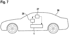
- Fig. 7 is a principle diagram of an embodiment of a vehicle 26, comprising an electric machine 1 according to one of the aforementioned embodiments, which is supplied by a pump 27 via a heat exchanger 28 for cooling the electric machine 1.
Description
- The present invention refers to a stator housing for an electric machine, comprising a plurality of axially extending main channels, wherein pairs of adjacent main channels are connected by deflection channels to form a meandering cooling path for a coolant. Besides, the present invention relates to an electric machine for a vehicle and a vehicle.
-
DE 10 2016 225 521 A1 discloses a housing for an electric machine with a cooling jacket, which surrounds a central axis annularly. The cooling jacket has circumferentially adjacent cooling jacket segments, each of which has a meandering cooling channel. The meandering cooling jacket segments are aligned such that respective two adjacent straight sections are configured to guide a coolant in opposite directions, where the straight sections are aligned transversely to a circumferential direction. - Further stator housings are disclosed in
KR 2017 0011865 A DE 10 2012 022 451 A1 ,TW I 624 137 B WO 03/100946 A1 EP 2 369 723 A2WO 2009/015946 A1 ,WO 2010/118792 A1 andJP 2007 143247 A - When operating an electric machine, electrical losses are proportional to a current injected to stator windings of the electric machine. Due to an electrical resistance of the stator windings, a higher heat is generated with increasing injected current. The heat may lead to a thermal failure of the material in active parts, particularly the stator windings, of the electric machine, when exceeding specific maximum rated temperatures. In order to increase the utilization of the electric machine, it is necessary to dissipate the heat by providing a fluid cooling, e.g. a water cooling, to the electric machine. It is known to integrate the fluid cooling within a stator housing of the electric machine, in which axial main channels and deflections channels that connect pairs of adjacent main channels are provided to form a meandering cooling path.
- However, with an increasing number of deflection channels and an increasing volume flow rate of the coolant a cooling efficiency and a pressure drop between a beginning and an end of the cooling path increases. As an undesired result, higher pressure drops require stronger fluid pumps.
- Thus, it is an object of the present invention to provide a stator housing with an improved cooling path that is particularly operable with a lower pressure drop.
- According to the present invention this object is solved by a stator housing according to
claim 1. - It has been found out that in a conventional meandering cooling path a highpressure area before a respective deflection channel and the low-pressure area behind the deflection channel emerge due to flow separation of the coolant. By adding the connection channels a pressure equalization between the highpressure area and the low-pressure area in the pair of adjacent main channels is realized which reduces a pressure drop between the pressure areas significantly. Therein, it has been identified that the effect of reducing the pressure drop is typically larger than an effect that reduces cooling efficiency of the stator housing due to a certain amount of coolant flowing through the connection channel, when comparing the stator housing according to the invention with a corresponding conventional stator housing without connection channels. Advantageously, weaker and particularly smaller fluid pumps can be used with the inventive stator housing due to the improvement of the cooling path with the lower pressure drop.
- Typically, the deflection channels may be configured to realize a deflection of the coolant flowing to the cooling path of at least 170°, preferably at least 175°, more preferably at least 179°. Preferably, the main channels extend parallelly in axial direction. Typically, the cooling channels are arranged at a central axial position pair of adjacent main channels. The central position may be between 40% and 60% of the total length of the pair of adjacent main channels. Typically, the cooling path comprises an inlet channel connected to a first main channel with respect to the flow direction of the coolant and/or an outlet channel connected to the last main channel with respect to the flow direction of the coolant. The inlet channel may be connected to the first main channel by means of a further deflection channel and/or the last main channel may be connection to the outlet channel by means of a further deflection channel. A further connection channels may be arranged between the inlet channel and the first main channel and/or a further connection channel may be arranged between the last main channel and outlet channel. The inlet channel and/or the outlet channel may be shaped such that it guides the coolant at least partially in a circumferential direction of the stator housing.
- Preferably, the connection channels have a smaller cross-sectional area than the main channels. It has been found out that small connection channels already provide a sufficient equalization between the pressure areas in the adjacent main channels without affecting the cooling efficiency heavily. In detail, the cross-sectional area of each connection channel may be at least two percent, preferably at least five percent, more preferably at least seven percent, and/or at most thirty percent, preferably at most twenty percent, more preferably at most ten percent, of the cross-sectional area of a main channel connected by the connection channels.
- Advantageously, the stator housing according to the invention is configured such that at least two percent, preferably at least five percent, more preferably at least ten percent, and/or at most thirty percent, preferably at most twenty percent, more preferably at most fifteen percent, of a mass flow of the coolant flowing through a main channel is bypassed through the connection channel connecting the main channel with its adjacent main channel.
- In general, the connection channels may have various cross-sections such as a circular, oval or rectangular shape. According to a very preferred embodiment of the stator housing according to the invention the connection channels have a trapezoid cross-section.
- In order to simplify manufacturing of the cooling path, it is preferred that the main channels and the connection channels, and particularly the deflection channels and/or the inlet channel and/or the outlet channel, are formed by a cavity in the stator housing. The respective cavities may be milled into a material forming the stator housing.
- Therein, sections of the cavity forming the main channels may be separated by a wall, wherein each connection channel connecting one of the pairs of adjacent main channels may be formed by a groove in the wall. Therein, it is preferred that the sections of the cavity forming the main channels are deeper than the grooves.
- The stator housing according to the invention may comprise an inner housing element and an outer housing element, wherein the inner housing element is coaxially arranged inside the outer housing element. Thereby, the stator housing may be simply manufactured in a modular manner.
- Therein, the cavity may be formed in one of the housing elements. According to a preferred design the cavity is formed in the inner housing element and closed by the outer housing element. Alternatively, the cavity may be formed in the outer housing element and closed by the inner housing element.
- Furthermore, one housing element may comprise a first end shield of the stator housing and one housing element may comprise a second end shield of the stator housing. Preferably, the first end shield is a drive end shield and the second end shield is a non-drive end shield. Preferably, an inlet connected to the inlet cooling path and/or an outlet connected to the outlet cooling path are integrally formed with the outer housing element. Preferably, the inlet and the outlet are arranged at opposing axial positions of the stator housing.
- Furthermore, the above object is solved by an electric machine according to
claim 13. - Besides, the above subject is solved by a vehicle according to
claim 14. The vehicle may be a fully electrically driven vehicle or a partially electrically driven vehicle such as a hybrid vehicle. - All statements referring to the inventive stator housing apply analogously to the inventive electric machine and to the inventive vehicle, so that the above-mentioned advantages of the stator housing may be achieved therewith as well.
- Further details and advantages of the invention are disclosed in the following, wherein reference is made to the schematic drawings showing:
- Fig. 1
- a principle cross-sectional view of an embodiment of an electric machine according to the invention comprising an embodiment of a stator housing according to the invention;
- Fig. 2
- an exploded view of the stator housing;
- Fig. 3
- a perspective view of a connection channel of the stator housing;
- Fig. 4
- stream lines of a coolant flowing along a cooling path of the stator housing during operation of the electric machine;
- Fig. 5
- a pressure distribution along the cooling path during operation of the electric machine;
- Fig. 6
- a temperature distribution of an inner housing element of the stator housing during operation of the electric machine; and
- Fig. 7
- a principle diagram of an embodiment of a vehicle according to the invention.
-
Fig. 1 is a principle cross-sectional view of an embodiment of anelectric machine 1 comprising an embodiment of astator housing 2, astator 3 being fixed inside thestator housing 2 by means of a press fit, a rotor 4 being rotatably arranged inside thestator 3 and ashaft 5, which is attached to the rotor 4. Exemplarily, the rotor 4 comprises multiple permanent magnets 6. -
Fig. 2 is an exploded view of thestator housing 2, which comprises acooling path 7 including by a plurality of axially extendingmain channels 8a to 8c anddeflection channels main channels 8a to 8c such that a coolant flowing through thecooling path 7 is deflected by 180°, when leaving a respectivemain channel 8a to 8c. Thus, thedeflection channels stator housing 2. Furthermore, thecooling path 7 comprisesconnection channels main channels 8a to 8c in a fluid conductive manner at a central axial position between thedeflection channels - Additionally, the
cooling path 7 comprises aninlet channel 11 and anoutlet channel 12, which differ from themain channels 8a to 8c in that they extend partially in circumferential direction and that they are configured to guide the coolant from aninlet 13 to the firstmain channel 8a with respect to a flow direction of the coolant (depicted by an arrow 15) or from a last main channel (not visible inFig. 2 ) with respect to the flow direction to anoutlet 14 of thestator housing 2, respectively. Therein, theinlet channel 11 and the firstmain channel 8a are connected by afurther deflection channel 9c and the last main channel and theoutlet channel 12 by afurther deflection channel 9d. Besides, afurther connection channel 10c is provided between theinlet channel 11 and the firstmain channel 8a and afurther connection channel 10d is provided between the last main channel and theoutlet channel 12, wherein axial positions of thefurther connection channels connection channels -
Fig. 3 is a perspective view of theconnection channel 10a, which is representative for theother connection channels connection channel 10a has the cross-sectional shape of an isosceles trapezoid, whose long parallel side is about 1.95 times as big as its short parallel side. The height of theconnection channel 10a is about 60% of the height of themain channel 8a, wherein an angle α being the inside angle between the long parallel side and a leg of the trapezoid is about 44.7°. The cross-sectional area of theconnection channel 10a is about 8 % of the cross-sectional area of themain channel 8a that is connected via aconnection channel 10a to themain channel 8b. This results in that about 12 % of the mass flow of the coolant flowing through themain channel 8a is bypassed through theconnection channel 10a without passing thedeflection channel 9a. - Again, with reference to
Fig. 2 the stator housing comprises aninner housing element 16 and anouter housing element 17. Theinner housing element 16 is coaxially arranged inside theouter housing element 17. Accordingly, themain channels 8a to 8c, thedeflection channels 9a to 9d, theconnection channels 10a to 10d, theinlet channel 11 and theoutlet channel 12 are formed by a cavity milled into a cylindrical structure of theinner housing element 16. Thus, the pairs of adjacentmain channels 8a to 8c are separated bywalls 18, wherein theconnection channels 10a to 10d are formed by respective grooves in thewalls 18. When being arranged inside theouter housing element 17, the cavity is closed by an inner cylindrical structure of theouter housing element 17. - Furthermore, the
inner housing element 16 comprises afirst end shield 19 being a drive end (DE) shield of theelectric machine 1 and theouter housing element 17 comprises asecond end shield 20 being the non-drive end (NDE) shield of the electric machine. Additionally, on both face sides of theinner housing element 16 sealing 21, 22 are arranged that seal theinner housing element 16 against theouter housing element 17. -
Fig. 4 shows stream lines of the coolant flowing along thecooling path 7 during operation of theelectric machine 1. In comparison to conventional stator housings without connection channels a flow separation and coolant circulation after having passed a deflection channel, is significantly reduced by an equalizing effect of the connection channels. -
Fig. 5 shows a pressure distribution along thecooling path 7 of thestator housing 2 during operation of theelectric machine 1 represented byisobars 23a to 23f. The coolant enters thecooling path 7 with a maximum pressure drop of exemplarily 3.5 kPa inside amaximum pressure area 23. Therein, theisobars 23a to 23f denote approximately the following pressure drops: 23a - 3,27 kPa; 23b - 3,03 kPa; 23c - 2,80 kPa; 23d - 2,57 kPa; 23e - 2,33 kPa; 23f - 0,00 kPa. - It has been determined that, in comparison to the conventional stator housing, the pressure drop is lowered by 37.53% for an inlet coolant temperature of 25 °C and lowered by 42.89% for an inlet coolant temperature of 65 °C when applying a respective volume flow rate of 10 l · min-1.
-
Fig. 6 shows a temperature distribution of theinner housing element 16 during operation of theelectric machine 1 represented by isotherms. As depicted byhotspot areas respective connection channel 10a to 10d of eachmain channel 8a to 8c, which are warmer than a single hotspot area in the conventional electric machine without connection channels. However, at a critical point (inlet temperature of 70 °C, volume flow rate of 6 l · min-1) the absolute temperature increase in comparison to conventional electric machine without connection channels is significantly lower than the pressure drop reduction realized by applying theconnection channels 10a to 10d, as denoted in the following table:Without connection channels With connection channels Heat increase DE housing max. temp. 361.65 K (88.50 °C) 362.96 K (89.81 °C) 0.36 % avg. temp. 350.15 K (77.00 °C) 351.63 K (78.48 °C) 0.42 % NDE housing max. temp. 351.15 K (78.00 °C) 354.56 K (81.41 °C) 0.97 % avg. temp. 346.65 K (73.50 °C) 348.34 K (75.19 °C) 0,49 % Press fit max. temp. 361.65 K (88.50 °C) 363.00 K (89.85 °C) 0.37 % avg. temp. 356.95 K (83.80 °C) 358.55 K (85.40 °C) 0.45 % Coolant wall max. temp. 360.65 K (87.50 °C) 361.99 K (88.84 °C) 0.37 % avg. temp. 352.65 K (79.50 °C) 354.26 K (81.11 °C) 0.46 % - Consequently, by providing the
connection channels 10a to 10d a significant reduction of the pressure drop across thecooling path 7 is realized at cost of only a very few raise of maximum and average temperatures at several interesting point of theelectric machine 1. -
Fig. 7 is a principle diagram of an embodiment of avehicle 26, comprising anelectric machine 1 according to one of the aforementioned embodiments, which is supplied by apump 27 via aheat exchanger 28 for cooling theelectric machine 1.
Claims (14)
- Stator housing (2) for an electric machine (1), comprising a plurality of main channels (8a, 8c) extending axially with respect to the rotation axis of the electric machine (1), wherein pairs of adjacent main channels (8a-8c) are connected by deflection channels (9a, 9b) to form a meandering cooling path (7) for a coolant,
characterized by
a plurality of connection channels (10a, 10b) that connect each pair of adjacent main channels (8a-8c) in a fluid conductive manner at an axial position between the deflection channels (9a, 9b). - Stator housing according to claim 1, wherein the connection channels (10a, 10b) have a smaller cross-sectional area than the main channels (8a-8c).
- Stator housing according to claim 2, wherein the cross-sectional area of each connection channel (10a, 10b) is at least two percent, preferably at least five percent, more preferably at least seven percent, and/or at most thirty percent, preferably at most twenty percent, more preferably at most ten percent, of the cross-sectional area of the main channels (8a-8c) connected by the connection channels (10a, 10b).
- Stator housing according to any of the preceding claims, which is configured such that at least two percent, preferably at least five percent, more preferably at least ten percent, and/or at most thirty percent, preferably at most twenty percent, more preferably at most fifteen percent, of a mass flow of the coolant flowing through a main channel (8a-8c) is bypassed through a connection channel (10a, 10b) connecting the main channel (8a-8c) with its adjacent main channel (8a-8c).
- Stator housing according to any of the preceding claims, wherein the connection channels (10a, 10b) have a trapezoid cross-section.
- Stator housing according to any of the preceding claims, wherein the main channels (8a-8c) and the connection channels (10a, 10b) are formed by a cavity in the stator housing (2).
- Stator housing according to claim 6, wherein sections of the cavity forming the main channels (8a-8c) are separated by a wall (18), wherein each connection channel (10a, 10b) connecting one of the pairs of adjacent main channels (8a-8c) is formed by a groove in the wall (18).
- Stator housing according to claim 7, wherein the sections of the cavity forming the main channels (8a-8c) are deeper than the grooves.
- Stator housing according to any of the preceding claims, which comprises an inner housing element (16) and an outer housing element (17), wherein the inner housing element (16) is coaxially arranged inside the outer housing element (17).
- Stator housing according to claims 6 and 9, wherein the cavity is formed in one of the housing elements (16).
- Stator housing according to claim 10, wherein the cavity is formed in the inner housing element (16) and closed by the outer housing element (17), or wherein the cavity is formed in the outer housing element (17) and closed by the inner housing element (16).
- Stator housing according to any of claims 9 to 11, wherein one housing element (16) comprises a first end shield (19) of the stator housing (2) and one housing element (17) comprises a second end shield (20) of the stator housing (2).
- Electric machine (1) for a vehicle (26), comprising a stator (3) arranged inside a stator housing (2) according to any of the preceding claims.
- Vehicle (26), comprising an electric machine (1) according to claim 13 that is configured to drive the vehicle (26).
Priority Applications (5)
| Application Number | Priority Date | Filing Date | Title |
|---|---|---|---|
| EP18209098.5A EP3661027B1 (en) | 2018-11-29 | 2018-11-29 | Stator housing for an electric machine, electric machine for a vehicle and vehicle |
| PL18209098T PL3661027T3 (en) | 2018-11-29 | 2018-11-29 | Stator housing for an electric machine, electric machine for a vehicle and vehicle |
| CN201911139836.9A CN111245145A (en) | 2018-11-29 | 2019-11-20 | Stator housing for an electric machine, electric machine for a vehicle and vehicle |
| US16/692,094 US11515755B2 (en) | 2018-11-29 | 2019-11-22 | Stator housing for an electric machine, electric machine for a vehicle and vehicle |
| JP2019214167A JP2020089268A (en) | 2018-11-29 | 2019-11-27 | Stator housing for electric machine, electric machine for vehicle, and vehicle |
Applications Claiming Priority (1)
| Application Number | Priority Date | Filing Date | Title |
|---|---|---|---|
| EP18209098.5A EP3661027B1 (en) | 2018-11-29 | 2018-11-29 | Stator housing for an electric machine, electric machine for a vehicle and vehicle |
Publications (2)
| Publication Number | Publication Date |
|---|---|
| EP3661027A1 EP3661027A1 (en) | 2020-06-03 |
| EP3661027B1 true EP3661027B1 (en) | 2022-01-05 |
Family
ID=64559508
Family Applications (1)
| Application Number | Title | Priority Date | Filing Date |
|---|---|---|---|
| EP18209098.5A Active EP3661027B1 (en) | 2018-11-29 | 2018-11-29 | Stator housing for an electric machine, electric machine for a vehicle and vehicle |
Country Status (5)
| Country | Link |
|---|---|
| US (1) | US11515755B2 (en) |
| EP (1) | EP3661027B1 (en) |
| JP (1) | JP2020089268A (en) |
| CN (1) | CN111245145A (en) |
| PL (1) | PL3661027T3 (en) |
Cited By (1)
| Publication number | Priority date | Publication date | Assignee | Title |
|---|---|---|---|---|
| WO2023186624A1 (en) * | 2022-03-29 | 2023-10-05 | Valeo Equipements Electriques Moteur | Rotary electric machine comprising a cooling chamber |
Families Citing this family (1)
| Publication number | Priority date | Publication date | Assignee | Title |
|---|---|---|---|---|
| JP7400888B1 (en) | 2022-07-14 | 2023-12-19 | 株式会社明電舎 | Coolant flow path structure in rotating machines |
Citations (1)
| Publication number | Priority date | Publication date | Assignee | Title |
|---|---|---|---|---|
| EP2940835A1 (en) * | 2014-04-29 | 2015-11-04 | Honeywell International Inc. | Electric motor-driven compressor having bi-directional liquid coolant passage |
Family Cites Families (16)
| Publication number | Priority date | Publication date | Assignee | Title |
|---|---|---|---|---|
| US6727611B2 (en) | 2002-05-28 | 2004-04-27 | Emerson Electric Co. | Cooling jacket for electric machines |
| JP2007143247A (en) * | 2005-11-16 | 2007-06-07 | Ishikawajima Harima Heavy Ind Co Ltd | Water-cooled motor, and method of processing waterway in its motor frame |
| DE102007035271A1 (en) * | 2007-07-27 | 2009-01-29 | Continental Automotive Gmbh | electric motor |
| DE102009001387A1 (en) * | 2009-03-06 | 2010-09-09 | Robert Bosch Gmbh | electric machine |
| DE102009017325A1 (en) | 2009-04-16 | 2010-10-21 | Avantis Ltd. | Generator cooling arrangement of a wind turbine |
| JP2011193571A (en) * | 2010-03-12 | 2011-09-29 | Nippon Soken Inc | Rotary electric machine |
| US8525375B2 (en) | 2010-03-23 | 2013-09-03 | Hamilton Sundstrand Corporation | Cooling arrangement for end turns and stator in an electric machine |
| US8970073B2 (en) * | 2010-10-19 | 2015-03-03 | Toyota Jidosha Kabushiki Kaisha | Cooling structure for rotary electric machine |
| DE102012022451B4 (en) * | 2012-11-09 | 2016-08-18 | Getrag Getriebe- Und Zahnradfabrik Hermann Hagenmeyer Gmbh & Cie Kg | Ring channel device, electric machine and drive train |
| DE112014002106T5 (en) * | 2013-05-30 | 2016-01-14 | Remy Technologies, Llc | Electric machine with liquid-cooled housing |
| CN103683673B (en) * | 2013-11-13 | 2016-08-17 | 华南理工大学 | A kind of directly fountain electromotor cooling system |
| US10483812B2 (en) * | 2014-12-31 | 2019-11-19 | Ingersoll-Rand Company | Electrical machine and method of manufacture |
| KR102490601B1 (en) * | 2015-07-24 | 2023-01-19 | 현대모비스 주식회사 | Dirve motor with one body style cooling structure |
| DE102016225521A1 (en) * | 2016-12-20 | 2018-06-21 | Bayerische Motoren Werke Aktiengesellschaft | Cooling jacket housing, in particular for an electrical machine |
| TWI624137B (en) * | 2017-03-23 | 2018-05-11 | Power module | |
| CN108336865B (en) * | 2018-03-30 | 2024-03-05 | 北京理工大学 | Liquid cooling driving motor |
-
2018
- 2018-11-29 PL PL18209098T patent/PL3661027T3/en unknown
- 2018-11-29 EP EP18209098.5A patent/EP3661027B1/en active Active
-
2019
- 2019-11-20 CN CN201911139836.9A patent/CN111245145A/en active Pending
- 2019-11-22 US US16/692,094 patent/US11515755B2/en active Active
- 2019-11-27 JP JP2019214167A patent/JP2020089268A/en active Pending
Patent Citations (1)
| Publication number | Priority date | Publication date | Assignee | Title |
|---|---|---|---|---|
| EP2940835A1 (en) * | 2014-04-29 | 2015-11-04 | Honeywell International Inc. | Electric motor-driven compressor having bi-directional liquid coolant passage |
Cited By (2)
| Publication number | Priority date | Publication date | Assignee | Title |
|---|---|---|---|---|
| WO2023186624A1 (en) * | 2022-03-29 | 2023-10-05 | Valeo Equipements Electriques Moteur | Rotary electric machine comprising a cooling chamber |
| FR3134260A1 (en) * | 2022-03-29 | 2023-10-06 | Valeo Equipements Electriques Moteur | Rotating electric machine comprising a cooling chamber |
Also Published As
| Publication number | Publication date |
|---|---|
| PL3661027T3 (en) | 2022-05-02 |
| EP3661027A1 (en) | 2020-06-03 |
| CN111245145A (en) | 2020-06-05 |
| US11515755B2 (en) | 2022-11-29 |
| JP2020089268A (en) | 2020-06-04 |
| US20200177055A1 (en) | 2020-06-04 |
Similar Documents
| Publication | Publication Date | Title |
|---|---|---|
| JP4486114B2 (en) | Rotating electric machine | |
| EP3661027B1 (en) | Stator housing for an electric machine, electric machine for a vehicle and vehicle | |
| JP5798298B2 (en) | Rotating electromechanical coil spacer block with flow deflection channels in its coil interface | |
| KR20140081936A (en) | Motor unit having cooling channel | |
| CN115995903A (en) | Cooling device for a stator of an electric motor of a motor vehicle, stator and motor vehicle | |
| DE102014110299A1 (en) | Electric machine | |
| EP1946427B1 (en) | Paddled rotor spaceblocks | |
| US20230013463A1 (en) | Stator housing for an electrical machine, electrical machine for a vehicle, and vehicle | |
| CA2399350C (en) | Flow-through spaceblocks with deflectors and method for increased electric generator endwinding cooling | |
| CN105990946B (en) | Has the motor housing component of dual-cooled runner | |
| RU2350006C1 (en) | Electrical machine stator | |
| US11515744B2 (en) | Stator housing for an electric machine, electric machine, and vehicle | |
| CN202696317U (en) | Rotor for electric rotating machine | |
| EP2503675A1 (en) | Ventilation system for an electric machine | |
| CN215817686U (en) | Motor stator cooling structure | |
| US20210194298A1 (en) | Stator housing for an electric machine, electric machine, and vehicle | |
| US20120080967A1 (en) | Dynamoelectric machine coil spaceblock having flow deflecting structure in coil facing surface thereof | |
| CN110690773A (en) | Motor assembly, compressor and air conditioner | |
| US20230268795A1 (en) | Cooling jacket for cooling permanent magnet synchronous electric motor | |
| EP2246963A2 (en) | Dynamoelectric Machine Coil Spaceblock Having Flow Deflecting Structure in Coil Facing Surface Thereof | |
| EP3855602B1 (en) | Enclosed electric machine | |
| CN220210038U (en) | Stator punching sheet, stator assembly, motor and vehicle | |
| CN219740048U (en) | Stator core, stator assembly, liquid cooling motor and electric drive system | |
| DE102017112890A1 (en) | pump assembly | |
| ITMI982858A1 (en) | FORCED CONVECTION HEAT EXCHANGER FOR ELECTRICEROTATING MACHINES |
Legal Events
| Date | Code | Title | Description |
|---|---|---|---|
| PUAI | Public reference made under article 153(3) epc to a published international application that has entered the european phase |
Free format text: ORIGINAL CODE: 0009012 |
|
| STAA | Information on the status of an ep patent application or granted ep patent |
Free format text: STATUS: THE APPLICATION HAS BEEN PUBLISHED |
|
| AK | Designated contracting states |
Kind code of ref document: A1 Designated state(s): AL AT BE BG CH CY CZ DE DK EE ES FI FR GB GR HR HU IE IS IT LI LT LU LV MC MK MT NL NO PL PT RO RS SE SI SK SM TR |
|
| AX | Request for extension of the european patent |
Extension state: BA ME |
|
| STAA | Information on the status of an ep patent application or granted ep patent |
Free format text: STATUS: REQUEST FOR EXAMINATION WAS MADE |
|
| STAA | Information on the status of an ep patent application or granted ep patent |
Free format text: STATUS: EXAMINATION IS IN PROGRESS |
|
| 17P | Request for examination filed |
Effective date: 20201013 |
|
| RBV | Designated contracting states (corrected) |
Designated state(s): AL AT BE BG CH CY CZ DE DK EE ES FI FR GB GR HR HU IE IS IT LI LT LU LV MC MK MT NL NO PL PT RO RS SE SI SK SM TR |
|
| STAA | Information on the status of an ep patent application or granted ep patent |
Free format text: STATUS: EXAMINATION IS IN PROGRESS |
|
| 17Q | First examination report despatched |
Effective date: 20201117 |
|
| GRAP | Despatch of communication of intention to grant a patent |
Free format text: ORIGINAL CODE: EPIDOSNIGR1 |
|
| STAA | Information on the status of an ep patent application or granted ep patent |
Free format text: STATUS: GRANT OF PATENT IS INTENDED |
|
| INTG | Intention to grant announced |
Effective date: 20210615 |
|
| GRAJ | Information related to disapproval of communication of intention to grant by the applicant or resumption of examination proceedings by the epo deleted |
Free format text: ORIGINAL CODE: EPIDOSDIGR1 |
|
| STAA | Information on the status of an ep patent application or granted ep patent |
Free format text: STATUS: EXAMINATION IS IN PROGRESS |
|
| GRAS | Grant fee paid |
Free format text: ORIGINAL CODE: EPIDOSNIGR3 |
|
| STAA | Information on the status of an ep patent application or granted ep patent |
Free format text: STATUS: GRANT OF PATENT IS INTENDED |
|
| GRAP | Despatch of communication of intention to grant a patent |
Free format text: ORIGINAL CODE: EPIDOSNIGR1 |
|
| INTC | Intention to grant announced (deleted) | ||
| GRAA | (expected) grant |
Free format text: ORIGINAL CODE: 0009210 |
|
| STAA | Information on the status of an ep patent application or granted ep patent |
Free format text: STATUS: THE PATENT HAS BEEN GRANTED |
|
| INTG | Intention to grant announced |
Effective date: 20211118 |
|
| AK | Designated contracting states |
Kind code of ref document: B1 Designated state(s): AL AT BE BG CH CY CZ DE DK EE ES FI FR GB GR HR HU IE IS IT LI LT LU LV MC MK MT NL NO PL PT RO RS SE SI SK SM TR |
|
| REG | Reference to a national code |
Ref country code: GB Ref legal event code: FG4D |
|
| REG | Reference to a national code |
Ref country code: CH Ref legal event code: EP |
|
| REG | Reference to a national code |
Ref country code: AT Ref legal event code: REF Ref document number: 1461467 Country of ref document: AT Kind code of ref document: T Effective date: 20220115 |
|
| REG | Reference to a national code |
Ref country code: DE Ref legal event code: R096 Ref document number: 602018029069 Country of ref document: DE |
|
| REG | Reference to a national code |
Ref country code: IE Ref legal event code: FG4D |
|
| REG | Reference to a national code |
Ref country code: LT Ref legal event code: MG9D |
|
| REG | Reference to a national code |
Ref country code: NL Ref legal event code: MP Effective date: 20220105 |
|
| REG | Reference to a national code |
Ref country code: AT Ref legal event code: MK05 Ref document number: 1461467 Country of ref document: AT Kind code of ref document: T Effective date: 20220105 |
|
| PG25 | Lapsed in a contracting state [announced via postgrant information from national office to epo] |
Ref country code: NL Free format text: LAPSE BECAUSE OF FAILURE TO SUBMIT A TRANSLATION OF THE DESCRIPTION OR TO PAY THE FEE WITHIN THE PRESCRIBED TIME-LIMIT Effective date: 20220105 |
|
| PG25 | Lapsed in a contracting state [announced via postgrant information from national office to epo] |
Ref country code: SE Free format text: LAPSE BECAUSE OF FAILURE TO SUBMIT A TRANSLATION OF THE DESCRIPTION OR TO PAY THE FEE WITHIN THE PRESCRIBED TIME-LIMIT Effective date: 20220105 Ref country code: RS Free format text: LAPSE BECAUSE OF FAILURE TO SUBMIT A TRANSLATION OF THE DESCRIPTION OR TO PAY THE FEE WITHIN THE PRESCRIBED TIME-LIMIT Effective date: 20220105 Ref country code: PT Free format text: LAPSE BECAUSE OF FAILURE TO SUBMIT A TRANSLATION OF THE DESCRIPTION OR TO PAY THE FEE WITHIN THE PRESCRIBED TIME-LIMIT Effective date: 20220505 Ref country code: NO Free format text: LAPSE BECAUSE OF FAILURE TO SUBMIT A TRANSLATION OF THE DESCRIPTION OR TO PAY THE FEE WITHIN THE PRESCRIBED TIME-LIMIT Effective date: 20220405 Ref country code: LT Free format text: LAPSE BECAUSE OF FAILURE TO SUBMIT A TRANSLATION OF THE DESCRIPTION OR TO PAY THE FEE WITHIN THE PRESCRIBED TIME-LIMIT Effective date: 20220105 Ref country code: HR Free format text: LAPSE BECAUSE OF FAILURE TO SUBMIT A TRANSLATION OF THE DESCRIPTION OR TO PAY THE FEE WITHIN THE PRESCRIBED TIME-LIMIT Effective date: 20220105 Ref country code: ES Free format text: LAPSE BECAUSE OF FAILURE TO SUBMIT A TRANSLATION OF THE DESCRIPTION OR TO PAY THE FEE WITHIN THE PRESCRIBED TIME-LIMIT Effective date: 20220105 Ref country code: BG Free format text: LAPSE BECAUSE OF FAILURE TO SUBMIT A TRANSLATION OF THE DESCRIPTION OR TO PAY THE FEE WITHIN THE PRESCRIBED TIME-LIMIT Effective date: 20220405 |
|
| PG25 | Lapsed in a contracting state [announced via postgrant information from national office to epo] |
Ref country code: LV Free format text: LAPSE BECAUSE OF FAILURE TO SUBMIT A TRANSLATION OF THE DESCRIPTION OR TO PAY THE FEE WITHIN THE PRESCRIBED TIME-LIMIT Effective date: 20220105 Ref country code: GR Free format text: LAPSE BECAUSE OF FAILURE TO SUBMIT A TRANSLATION OF THE DESCRIPTION OR TO PAY THE FEE WITHIN THE PRESCRIBED TIME-LIMIT Effective date: 20220406 Ref country code: FI Free format text: LAPSE BECAUSE OF FAILURE TO SUBMIT A TRANSLATION OF THE DESCRIPTION OR TO PAY THE FEE WITHIN THE PRESCRIBED TIME-LIMIT Effective date: 20220105 Ref country code: AT Free format text: LAPSE BECAUSE OF FAILURE TO SUBMIT A TRANSLATION OF THE DESCRIPTION OR TO PAY THE FEE WITHIN THE PRESCRIBED TIME-LIMIT Effective date: 20220105 |
|
| RAP4 | Party data changed (patent owner data changed or rights of a patent transferred) |
Owner name: VALEO EAUTOMOTIVE GERMANY GMBH |
|
| REG | Reference to a national code |
Ref country code: DE Ref legal event code: R081 Ref document number: 602018029069 Country of ref document: DE Owner name: VALEO EAUTOMOTIVE GERMANY GMBH, DE Free format text: FORMER OWNER: VALEO SIEMENS EAUTOMOTIVE GERMANY GMBH, 91056 ERLANGEN, DE |
|
| PG25 | Lapsed in a contracting state [announced via postgrant information from national office to epo] |
Ref country code: IS Free format text: LAPSE BECAUSE OF FAILURE TO SUBMIT A TRANSLATION OF THE DESCRIPTION OR TO PAY THE FEE WITHIN THE PRESCRIBED TIME-LIMIT Effective date: 20220505 |
|
| REG | Reference to a national code |
Ref country code: DE Ref legal event code: R097 Ref document number: 602018029069 Country of ref document: DE |
|
| PG25 | Lapsed in a contracting state [announced via postgrant information from national office to epo] |
Ref country code: SM Free format text: LAPSE BECAUSE OF FAILURE TO SUBMIT A TRANSLATION OF THE DESCRIPTION OR TO PAY THE FEE WITHIN THE PRESCRIBED TIME-LIMIT Effective date: 20220105 Ref country code: SK Free format text: LAPSE BECAUSE OF FAILURE TO SUBMIT A TRANSLATION OF THE DESCRIPTION OR TO PAY THE FEE WITHIN THE PRESCRIBED TIME-LIMIT Effective date: 20220105 Ref country code: RO Free format text: LAPSE BECAUSE OF FAILURE TO SUBMIT A TRANSLATION OF THE DESCRIPTION OR TO PAY THE FEE WITHIN THE PRESCRIBED TIME-LIMIT Effective date: 20220105 Ref country code: EE Free format text: LAPSE BECAUSE OF FAILURE TO SUBMIT A TRANSLATION OF THE DESCRIPTION OR TO PAY THE FEE WITHIN THE PRESCRIBED TIME-LIMIT Effective date: 20220105 Ref country code: DK Free format text: LAPSE BECAUSE OF FAILURE TO SUBMIT A TRANSLATION OF THE DESCRIPTION OR TO PAY THE FEE WITHIN THE PRESCRIBED TIME-LIMIT Effective date: 20220105 Ref country code: CZ Free format text: LAPSE BECAUSE OF FAILURE TO SUBMIT A TRANSLATION OF THE DESCRIPTION OR TO PAY THE FEE WITHIN THE PRESCRIBED TIME-LIMIT Effective date: 20220105 |
|
| PLBE | No opposition filed within time limit |
Free format text: ORIGINAL CODE: 0009261 |
|
| STAA | Information on the status of an ep patent application or granted ep patent |
Free format text: STATUS: NO OPPOSITION FILED WITHIN TIME LIMIT |
|
| PG25 | Lapsed in a contracting state [announced via postgrant information from national office to epo] |
Ref country code: AL Free format text: LAPSE BECAUSE OF FAILURE TO SUBMIT A TRANSLATION OF THE DESCRIPTION OR TO PAY THE FEE WITHIN THE PRESCRIBED TIME-LIMIT Effective date: 20220105 |
|
| 26N | No opposition filed |
Effective date: 20221006 |
|
| PG25 | Lapsed in a contracting state [announced via postgrant information from national office to epo] |
Ref country code: SI Free format text: LAPSE BECAUSE OF FAILURE TO SUBMIT A TRANSLATION OF THE DESCRIPTION OR TO PAY THE FEE WITHIN THE PRESCRIBED TIME-LIMIT Effective date: 20220105 |
|
| PGFP | Annual fee paid to national office [announced via postgrant information from national office to epo] |
Ref country code: PL Payment date: 20221017 Year of fee payment: 5 |
|
| PG25 | Lapsed in a contracting state [announced via postgrant information from national office to epo] |
Ref country code: MC Free format text: LAPSE BECAUSE OF FAILURE TO SUBMIT A TRANSLATION OF THE DESCRIPTION OR TO PAY THE FEE WITHIN THE PRESCRIBED TIME-LIMIT Effective date: 20220105 |
|
| REG | Reference to a national code |
Ref country code: CH Ref legal event code: PL |
|
| P01 | Opt-out of the competence of the unified patent court (upc) registered |
Effective date: 20230528 |
|
| REG | Reference to a national code |
Ref country code: BE Ref legal event code: MM Effective date: 20221130 |
|
| PG25 | Lapsed in a contracting state [announced via postgrant information from national office to epo] |
Ref country code: LI Free format text: LAPSE BECAUSE OF NON-PAYMENT OF DUE FEES Effective date: 20221130 Ref country code: IT Free format text: LAPSE BECAUSE OF FAILURE TO SUBMIT A TRANSLATION OF THE DESCRIPTION OR TO PAY THE FEE WITHIN THE PRESCRIBED TIME-LIMIT Effective date: 20220105 Ref country code: CH Free format text: LAPSE BECAUSE OF NON-PAYMENT OF DUE FEES Effective date: 20221130 |
|
| PG25 | Lapsed in a contracting state [announced via postgrant information from national office to epo] |
Ref country code: LU Free format text: LAPSE BECAUSE OF NON-PAYMENT OF DUE FEES Effective date: 20221129 |
|
| PG25 | Lapsed in a contracting state [announced via postgrant information from national office to epo] |
Ref country code: IE Free format text: LAPSE BECAUSE OF NON-PAYMENT OF DUE FEES Effective date: 20221129 |
|
| PG25 | Lapsed in a contracting state [announced via postgrant information from national office to epo] |
Ref country code: BE Free format text: LAPSE BECAUSE OF NON-PAYMENT OF DUE FEES Effective date: 20221130 |
|
| PGFP | Annual fee paid to national office [announced via postgrant information from national office to epo] |
Ref country code: GB Payment date: 20231120 Year of fee payment: 6 |
|
| PGFP | Annual fee paid to national office [announced via postgrant information from national office to epo] |
Ref country code: FR Payment date: 20231124 Year of fee payment: 6 Ref country code: DE Payment date: 20231107 Year of fee payment: 6 |
|
| PGFP | Annual fee paid to national office [announced via postgrant information from national office to epo] |
Ref country code: PL Payment date: 20231018 Year of fee payment: 6 |
|
| PG25 | Lapsed in a contracting state [announced via postgrant information from national office to epo] |
Ref country code: HU Free format text: LAPSE BECAUSE OF FAILURE TO SUBMIT A TRANSLATION OF THE DESCRIPTION OR TO PAY THE FEE WITHIN THE PRESCRIBED TIME-LIMIT; INVALID AB INITIO Effective date: 20181129 |