EP4557263A1 - Vorrichtung und verfahren zur beobachtung eines blutgefässmodells - Google Patents
Vorrichtung und verfahren zur beobachtung eines blutgefässmodells Download PDFInfo
- Publication number
- EP4557263A1 EP4557263A1 EP23839668.3A EP23839668A EP4557263A1 EP 4557263 A1 EP4557263 A1 EP 4557263A1 EP 23839668 A EP23839668 A EP 23839668A EP 4557263 A1 EP4557263 A1 EP 4557263A1
- Authority
- EP
- European Patent Office
- Prior art keywords
- image
- infrared light
- observation
- blood vessel
- light
- Prior art date
- Legal status (The legal status is an assumption and is not a legal conclusion. Google has not performed a legal analysis and makes no representation as to the accuracy of the status listed.)
- Pending
Links
Images





Classifications
-
- A—HUMAN NECESSITIES
- A61—MEDICAL OR VETERINARY SCIENCE; HYGIENE
- A61B—DIAGNOSIS; SURGERY; IDENTIFICATION
- A61B5/00—Measuring for diagnostic purposes; Identification of persons
- A61B5/0059—Measuring for diagnostic purposes; Identification of persons using light, e.g. diagnosis by transillumination, diascopy, fluorescence
- A61B5/0062—Arrangements for scanning
- A61B5/0066—Optical coherence imaging
-
- H—ELECTRICITY
- H04—ELECTRIC COMMUNICATION TECHNIQUE
- H04N—PICTORIAL COMMUNICATION, e.g. TELEVISION
- H04N23/00—Cameras or camera modules comprising electronic image sensors; Control thereof
- H04N23/50—Constructional details
- H04N23/555—Constructional details for picking-up images in sites, inaccessible due to their dimensions or hazardous conditions, e.g. endoscopes or borescopes
-
- A—HUMAN NECESSITIES
- A61—MEDICAL OR VETERINARY SCIENCE; HYGIENE
- A61B—DIAGNOSIS; SURGERY; IDENTIFICATION
- A61B5/00—Measuring for diagnostic purposes; Identification of persons
- A61B5/0059—Measuring for diagnostic purposes; Identification of persons using light, e.g. diagnosis by transillumination, diascopy, fluorescence
- A61B5/0082—Measuring for diagnostic purposes; Identification of persons using light, e.g. diagnosis by transillumination, diascopy, fluorescence adapted for particular medical purposes
- A61B5/0084—Measuring for diagnostic purposes; Identification of persons using light, e.g. diagnosis by transillumination, diascopy, fluorescence adapted for particular medical purposes for introduction into the body, e.g. by catheters
- A61B5/0086—Measuring for diagnostic purposes; Identification of persons using light, e.g. diagnosis by transillumination, diascopy, fluorescence adapted for particular medical purposes for introduction into the body, e.g. by catheters using infrared radiation
-
- A—HUMAN NECESSITIES
- A61—MEDICAL OR VETERINARY SCIENCE; HYGIENE
- A61B—DIAGNOSIS; SURGERY; IDENTIFICATION
- A61B5/00—Measuring for diagnostic purposes; Identification of persons
- A61B5/02—Detecting, measuring or recording for evaluating the cardiovascular system, e.g. pulse, heart rate, blood pressure or blood flow
- A61B5/02007—Evaluating blood vessel condition, e.g. elasticity, compliance
-
- A—HUMAN NECESSITIES
- A61—MEDICAL OR VETERINARY SCIENCE; HYGIENE
- A61B—DIAGNOSIS; SURGERY; IDENTIFICATION
- A61B5/00—Measuring for diagnostic purposes; Identification of persons
- A61B5/06—Devices, other than using radiation, for detecting or locating foreign bodies ; Determining position of diagnostic devices within or on the body of the patient
-
- A—HUMAN NECESSITIES
- A61—MEDICAL OR VETERINARY SCIENCE; HYGIENE
- A61B—DIAGNOSIS; SURGERY; IDENTIFICATION
- A61B5/00—Measuring for diagnostic purposes; Identification of persons
- A61B5/48—Other medical applications
- A61B5/4887—Locating particular structures in or on the body
- A61B5/489—Blood vessels
-
- G—PHYSICS
- G01—MEASURING; TESTING
- G01N—INVESTIGATING OR ANALYSING MATERIALS BY DETERMINING THEIR CHEMICAL OR PHYSICAL PROPERTIES
- G01N21/00—Investigating or analysing materials by the use of optical means, i.e. using sub-millimetre waves, infrared, visible or ultraviolet light
- G01N21/17—Systems in which incident light is modified in accordance with the properties of the material investigated
- G01N21/25—Colour; Spectral properties, i.e. comparison of effect of material on the light at two or more different wavelengths or wavelength bands
- G01N21/31—Investigating relative effect of material at wavelengths characteristic of specific elements or molecules, e.g. atomic absorption spectrometry
- G01N21/35—Investigating relative effect of material at wavelengths characteristic of specific elements or molecules, e.g. atomic absorption spectrometry using infrared light
- G01N21/359—Investigating relative effect of material at wavelengths characteristic of specific elements or molecules, e.g. atomic absorption spectrometry using infrared light using near infrared light
-
- G—PHYSICS
- G06—COMPUTING OR CALCULATING; COUNTING
- G06T—IMAGE DATA PROCESSING OR GENERATION, IN GENERAL
- G06T11/00—Two-dimensional [2D] image generation
-
- G—PHYSICS
- G06—COMPUTING OR CALCULATING; COUNTING
- G06T—IMAGE DATA PROCESSING OR GENERATION, IN GENERAL
- G06T5/00—Image enhancement or restoration
- G06T5/50—Image enhancement or restoration using two or more images, e.g. averaging or subtraction
-
- G—PHYSICS
- G06—COMPUTING OR CALCULATING; COUNTING
- G06T—IMAGE DATA PROCESSING OR GENERATION, IN GENERAL
- G06T7/00—Image analysis
- G06T7/0002—Inspection of images, e.g. flaw detection
- G06T7/0012—Biomedical image inspection
- G06T7/0014—Biomedical image inspection using an image reference approach
-
- G—PHYSICS
- G09—EDUCATION; CRYPTOGRAPHY; DISPLAY; ADVERTISING; SEALS
- G09B—EDUCATIONAL OR DEMONSTRATION APPLIANCES; APPLIANCES FOR TEACHING, OR COMMUNICATING WITH, THE BLIND, DEAF OR MUTE; MODELS; PLANETARIA; GLOBES; MAPS; DIAGRAMS
- G09B19/00—Teaching not covered by other main groups of this subclass
- G09B19/24—Use of tools
-
- G—PHYSICS
- G09—EDUCATION; CRYPTOGRAPHY; DISPLAY; ADVERTISING; SEALS
- G09B—EDUCATIONAL OR DEMONSTRATION APPLIANCES; APPLIANCES FOR TEACHING, OR COMMUNICATING WITH, THE BLIND, DEAF OR MUTE; MODELS; PLANETARIA; GLOBES; MAPS; DIAGRAMS
- G09B23/00—Models for scientific, medical, or mathematical purposes, e.g. full-sized devices for demonstration purposes
- G09B23/28—Models for scientific, medical, or mathematical purposes, e.g. full-sized devices for demonstration purposes for medicine
- G09B23/285—Models for scientific, medical, or mathematical purposes, e.g. full-sized devices for demonstration purposes for medicine for injections, endoscopy, bronchoscopy, sigmoidscopy, insertion of contraceptive devices or enemas
-
- G—PHYSICS
- G09—EDUCATION; CRYPTOGRAPHY; DISPLAY; ADVERTISING; SEALS
- G09B—EDUCATIONAL OR DEMONSTRATION APPLIANCES; APPLIANCES FOR TEACHING, OR COMMUNICATING WITH, THE BLIND, DEAF OR MUTE; MODELS; PLANETARIA; GLOBES; MAPS; DIAGRAMS
- G09B23/00—Models for scientific, medical, or mathematical purposes, e.g. full-sized devices for demonstration purposes
- G09B23/28—Models for scientific, medical, or mathematical purposes, e.g. full-sized devices for demonstration purposes for medicine
- G09B23/286—Models for scientific, medical, or mathematical purposes, e.g. full-sized devices for demonstration purposes for medicine for scanning or photography techniques, e.g. X-rays, ultrasonics
-
- G—PHYSICS
- G09—EDUCATION; CRYPTOGRAPHY; DISPLAY; ADVERTISING; SEALS
- G09B—EDUCATIONAL OR DEMONSTRATION APPLIANCES; APPLIANCES FOR TEACHING, OR COMMUNICATING WITH, THE BLIND, DEAF OR MUTE; MODELS; PLANETARIA; GLOBES; MAPS; DIAGRAMS
- G09B23/00—Models for scientific, medical, or mathematical purposes, e.g. full-sized devices for demonstration purposes
- G09B23/28—Models for scientific, medical, or mathematical purposes, e.g. full-sized devices for demonstration purposes for medicine
- G09B23/30—Anatomical models
-
- G—PHYSICS
- G09—EDUCATION; CRYPTOGRAPHY; DISPLAY; ADVERTISING; SEALS
- G09B—EDUCATIONAL OR DEMONSTRATION APPLIANCES; APPLIANCES FOR TEACHING, OR COMMUNICATING WITH, THE BLIND, DEAF OR MUTE; MODELS; PLANETARIA; GLOBES; MAPS; DIAGRAMS
- G09B23/00—Models for scientific, medical, or mathematical purposes, e.g. full-sized devices for demonstration purposes
- G09B23/28—Models for scientific, medical, or mathematical purposes, e.g. full-sized devices for demonstration purposes for medicine
- G09B23/30—Anatomical models
- G09B23/303—Anatomical models specially adapted to simulate circulation of bodily fluids
-
- H—ELECTRICITY
- H04—ELECTRIC COMMUNICATION TECHNIQUE
- H04N—PICTORIAL COMMUNICATION, e.g. TELEVISION
- H04N23/00—Cameras or camera modules comprising electronic image sensors; Control thereof
- H04N23/10—Cameras or camera modules comprising electronic image sensors; Control thereof for generating image signals from different wavelengths
- H04N23/11—Cameras or camera modules comprising electronic image sensors; Control thereof for generating image signals from different wavelengths for generating image signals from visible and infrared light wavelengths
-
- H—ELECTRICITY
- H04—ELECTRIC COMMUNICATION TECHNIQUE
- H04N—PICTORIAL COMMUNICATION, e.g. TELEVISION
- H04N23/00—Cameras or camera modules comprising electronic image sensors; Control thereof
- H04N23/70—Circuitry for compensating brightness variation in the scene
- H04N23/74—Circuitry for compensating brightness variation in the scene by influencing the scene brightness using illuminating means
-
- G—PHYSICS
- G06—COMPUTING OR CALCULATING; COUNTING
- G06T—IMAGE DATA PROCESSING OR GENERATION, IN GENERAL
- G06T2207/00—Indexing scheme for image analysis or image enhancement
- G06T2207/10—Image acquisition modality
- G06T2207/10048—Infrared image
-
- G—PHYSICS
- G06—COMPUTING OR CALCULATING; COUNTING
- G06T—IMAGE DATA PROCESSING OR GENERATION, IN GENERAL
- G06T2207/00—Indexing scheme for image analysis or image enhancement
- G06T2207/10—Image acquisition modality
- G06T2207/10068—Endoscopic image
-
- G—PHYSICS
- G06—COMPUTING OR CALCULATING; COUNTING
- G06T—IMAGE DATA PROCESSING OR GENERATION, IN GENERAL
- G06T2207/00—Indexing scheme for image analysis or image enhancement
- G06T2207/10—Image acquisition modality
- G06T2207/10141—Special mode during image acquisition
- G06T2207/10152—Varying illumination
-
- G—PHYSICS
- G06—COMPUTING OR CALCULATING; COUNTING
- G06T—IMAGE DATA PROCESSING OR GENERATION, IN GENERAL
- G06T2207/00—Indexing scheme for image analysis or image enhancement
- G06T2207/20—Special algorithmic details
- G06T2207/20212—Image combination
- G06T2207/20221—Image fusion; Image merging
-
- G—PHYSICS
- G06—COMPUTING OR CALCULATING; COUNTING
- G06T—IMAGE DATA PROCESSING OR GENERATION, IN GENERAL
- G06T2207/00—Indexing scheme for image analysis or image enhancement
- G06T2207/30—Subject of image; Context of image processing
- G06T2207/30004—Biomedical image processing
- G06T2207/30021—Catheter; Guide wire
-
- G—PHYSICS
- G06—COMPUTING OR CALCULATING; COUNTING
- G06T—IMAGE DATA PROCESSING OR GENERATION, IN GENERAL
- G06T2207/00—Indexing scheme for image analysis or image enhancement
- G06T2207/30—Subject of image; Context of image processing
- G06T2207/30004—Biomedical image processing
- G06T2207/30101—Blood vessel; Artery; Vein; Vascular
-
- G—PHYSICS
- G06—COMPUTING OR CALCULATING; COUNTING
- G06T—IMAGE DATA PROCESSING OR GENERATION, IN GENERAL
- G06T2210/00—Indexing scheme for image generation or computer graphics
- G06T2210/41—Medical
Definitions
- the present invention relates to a device and a method for observing a blood vessel model and a catheter inserted into said blood vessel model.
- blood vessel shape a shape of a blood vessel model
- a visible light camera or an X-ray projection device is often used in addition to direct visual observation.
- a blood vessel model By forming a blood vessel model with a transparent material and filling a lumen portion (hereinafter, referred to as "lumen region") of said blood vessel model with a liquid colored with a pigment or the like, a method of visually observing the blood vessel shape and the catheter inserted into the blood vessel model or observing the blood vessel shape and the catheter with a visible light camera is simple. However, in this case, since the catheter cannot be seen through and the position and state of a guide wire or the like constituting the catheter cannot be confirmed, the reproducibility of the intravascular surgery is low. This problem can be solved by using an X-ray, but it is not easy to use the X-ray from the viewpoint of radiation exposure and management.
- a catheter has a multilayer structure in which wires (balloon, coil, stent or the like having a therapeutic function, drug (liquid such as contrast medium or thrombolytic agent), and other sheath) are inserted into a thin tubular sheath, and it is not possible to detect a distal end position and a state of the wires inserted into the sheath in a multilayer manner by observation using visible light.
- wires balloon, coil, stent or the like having a therapeutic function, drug (liquid such as contrast medium or thrombolytic agent), and other sheath
- a material that does not transmit an X-ray is attached to a distal end, an intermediate portion, or the like of the sheath or the wires in order to clearly indicate a specific position of the sheath or the wires, and it is possible to confirm a relative position of each of the sheath or the wires in the X-ray projection device used at the time of treatment.
- Non-Patent Literature 1 An observation method combining a fluorescence observation technique and an image processing technique has been proposed in order to enable observation of a distal end position and a state of wires in a sheath while avoiding exposure to X-rays.
- Patent Literature 1 proposes a lubricating liquid that ensures lubricity between a blood vessel model and a catheter.
- Patent Literature 1 JP 5992031 B2
- Non-Patent Literature 1 Kazuaki Fukasaku et al. "Endovascular treatment training is enabled at anytime and anywhere - Developing simulation of endovascular treatment that does not expose doctors to X-rays -", [online], February 19, 2022, The 51st Japan Society for Neuroradiology https://www.u-ryukyu.ac.jp/news/32074/
- Non-Patent Literature 1 According to the observation method introduced in Non-Patent Literature 1, it is necessary to attach a fluorescent material to each portion of the sheath and wires of the catheter to be visualized. In other words, the actual catheter cannot be used as it is.
- a contrast medium liquid containing a fluorescent dye
- the blood vessel model is formed of a gel material made of polyvinyl alcohol or the like
- the contrast medium exudes into a blood vessel model forming material or adheres to an inner surface of the blood vessel model, and thus it is difficult to withstand long-term use.
- the blood vessel model is formed of a crosslinked polymer material such as silicone rubber
- a lubricating liquid in order to ensure lubricity between the catheter and the blood vessel model (see Patent Literature 1).
- the contrast medium is mixed with the lubricating liquid, the lubricating function of the lubricating liquid may be deteriorated.
- the present inventors have found that by using near-infrared light having higher substance permeability than visible light and variously changing a light absorption rate depending on the material and wavelength as compared with visible light, the blood vessel shape and the state inside the catheter can be simultaneously or selectively visualized without using a contrast medium or the like. That is, it is not necessary to attach the contrast medium or the fluorescent material required in the prior art to the sheath or the wires of the catheter.
- the near-infrared absorption rate varies depending on the type of substance and the wavelength of near-infrared light to be used. According to this characteristic, in near-infrared spectroscopy, a change in absorption rate in a near-infrared region is measured, and a component of a substance is specified by comparing a measurement result with a spectrum table showing absorption characteristics. Furthermore, in many substances, the absorption rate is greatly different in the visible light region and the near-infrared region.
- a liquid containing a dye or the like that appears opaque in the visible light region can be observed transparently in the near-infrared region, and various soft polymers such as silicone rubber that appears transparent in the visible light region, various hard polymers such as an acrylic resin, and various liquids such as water and oil can be observed (hereinafter, referred to as "near-infrared spectroscopic observation") as different colors (shades) in the near-infrared region without using a contrast agent or the like.
- the near-infrared absorption rate (that is, near-infrared transmittance) of each substance is variously changed by changing the wavelength in the near-infrared region, it is possible to identify a difference in shape and material of each part of the composite structure including different substances by using this characteristic.
- the inventors of the present invention have found that, by performing the near-infrared spectroscopic observation due to this feature of near-infrared light, it is possible to observe each part of the blood vessel model, which is entirely transparent in the visible light region including the inside and outside, as an image in which shape and a difference in material can be identified as a different color (shade) without using a contrast medium or the like. Furthermore, it has been found that by changing the wavelength and light amount of the near-infrared light to be used (the intensity of a light source and the exposure setting of an observation device), the balance of shades of each part of the blood vessel model can be changed without applying a physical operation to the observation target. Furthermore, it has been found that the blood vessel shape can be selectively visualized or eliminated while the fluoroscopic image of the catheter is visualized on an observation screen by changing the wavelength and light amount of the near-infrared light.
- the near-infrared light has a property of easily transmitting various materials, and thus, it is possible to perform fluoroscopic observation (hereinafter, referred to as "near-infrared fluoroscopic observation") of an object.
- fluoroscopic observation hereinafter, referred to as "near-infrared fluoroscopic observation”
- it is used for non-destructive inspection of semiconductors and the like, inspection of foreign matters in liquids, and the like.
- the blood vessel model is observed stereoscopically (3D), but according to the near-infrared fluoroscopic observation, a planar (2D) image like a shadow picture is obtained due to its permeability.
- a planar (2D) image is close to an X-ray fluoroscopic image obtained as in the catheter intravascular surgery, and is suitable for reproducing the simulation of the same surgery.
- a planar (2D) fluoroscopic image similar to the X-ray observation image can be obtained.
- the catheter of an actual machine has a thin film-like multilayer structure as a common feature, but the constituent material of the sheath and the film thickness thereof are not uniform depending on the type (as a constituent material of the sheath, various soft resins such as polyester, polyethylene, polyamide (nylon), polyurethane, and silicone rubber are used). Furthermore, metal structures such as a mesh and an X-ray opaque marker, mechanical structures such as a balloon and a coil detachment mechanism, and the like are complicatedly incorporated in the catheter and the wires.
- the inventors have found that by performing observation incorporating two aspects, the near-infrared fluoroscopic observation and the near-infrared spectroscopic observation, the catheter can be reproduced as an image close to an X-ray observation image at the time of actual surgery and further as a function-expanded observation image including information that cannot be obtained by the X-ray observation.
- the near-infrared light By using the near-infrared light, it is possible to perform fluoroscopic observation of the catheter and obtain an observation image capable of identifying a difference in structure and material thereof, and further, by changing the wavelength and light amount of the near-infrared light to be used, it is possible to change the shading balance of the observation image without applying a physical operation to the blood vessel model. For example, it is possible to select a specific region of the blood vessel model to be observed, change or reverse the shading balance of the selected specific region, and visualize or eliminate the specific region.
- a first aspect of the present invention is defined as follows.
- An observation device that observes a blood vessel model as an observation target into which a catheter is inserted, the blood vessel model including a substance disposed inside having near-infrared light absorption characteristics different from that of a constituent material of the blood vessel model, and the catheter including a sheath and wires inserted into the sheath, the observation device including: a first light source that emits first near-infrared light; a first light reception unit that can receive the first near-infrared light; a first image generation unit that generates a first image based on the first near-infrared light captured by the first light reception unit; and a display that displays the first image.
- the substance disposed in the blood vessel model has near-infrared light absorption characteristics different from that of the constituent material of the blood vessel model, it is possible to visually recognize a boundary between a blood vessel wall cross-sectional region (hereinafter, referred to as a "wall cross-sectional region") of the blood vessel model and the substance in near-infrared spectroscopic observation.
- a blood vessel wall cross-sectional region hereinafter, referred to as a "wall cross-sectional region”
- the catheter inserted into the blood vessel model has permeability different from the constituent material of the blood vessel model and the substance with respect to near-infrared light, the catheter can be observed distinguishably from the blood vessel model and the substance.
- a second aspect of the present invention is defined as follows.
- An observation method of an observation target using the observation device according to the first aspect including:
- the blood vessel model and the catheter inserted into the blood vessel model can be distinguished and observed by the near-infrared spectroscopic observation.
- the light amount of the first near-infrared light used for generating the first image as necessary, it is possible to display the fluoroscopic image of the catheter together with the blood vessel model on the image of the display. That is, near-infrared light fluoroscopic observation can be performed by adjusting the light amount of the near-infrared light.
- the light amount is adjusted in advance, so that the light amount does not need to be adjusted at the time of observation (hereinafter, the same applies to this specification).
- the observation method of the blood vessel model defined in the second aspect is practical.
- an adjustment device that adjusts the light amount of the near-infrared light
- a device that is attached to a light source of near-infrared light and adjusts a light amount of near-infrared light emitted from the light source a diaphragm that is attached to a light reception unit such as a camera and adjusts a light amount of light collected by the camera, a device that processes an image captured by the camera and adjusts an amount of light, and the like can be used.
- a third aspect of the present invention utilizes near-infrared reflection observation.
- the reflection characteristics of near-infrared light vary depending on a material irradiated with the near-infrared light. For example, there is a difference in reflection characteristics between iron (stainless steel) and platinum.
- the wires constituting the catheter there is a wire in which platinum is attached to the middle of a stainless wire to form an X-ray opaque marker. Since both stainless steel and platinum do not transmit near-infrared light, neither near-infrared spectroscopic observation nor near-infrared fluoroscopic observation is effective for such a wire.
- stainless steel and platinum have different near-infrared reflection characteristics
- a second near-infrared light source to condense reflected light from an object (in the above example, a wire including a platinum marker) on a light reception unit
- stainless steel that is a base metal of the wire and platinum that is a marker can be observed distinguishably. This observation can be performed together with the near-infrared spectroscopic observation and the near-infrared fluoroscopic observation described in the second aspect.
- a third aspect of the present invention is defined as follows. That is,
- An observation method by the observation device of the third aspect defined as described above is as follows.
- observation method of an observation target using the observation device including:
- the sheath of the catheter, the wires in the sheath, an X-ray opaque marker of the wires, and the blood vessel model can be visually recognized at the same time.
- the observation device is defined as follows. That is, the observation device according to the third aspect, further including:
- An observation method by the observation device of the fifth aspect defined as described above is as follows.
- observation method using the observation device according to the fifth aspect including:
- the observation device according to a seventh aspect of the present invention is defined as follows.
- observation device further including:
- An observation method by the observation device according to the seventh aspect defined as described above is as follows.
- observation method of an observation target using the observation device including:
- the wavelengths of the near-infrared light from the first light source and the second light source are not 1300 nm to 1550 nm, and near-infrared light having a wavelength that is less affected by absorption by water can be used. Since an amount of water through which the first near-infrared light from the first light source are transmitted is different from an amount of water through which the second near-infrared light from the second light source are transmitted, in a case where near-infrared light having a wavelength that is greatly affected by light absorption are used, it is difficult to clearly display the transmitted image by the first light source and the reflected image by the second light source at the same time.
- the second light source it is preferable to form the second light source with an LED of 1300 nm or less which is industrially easily available and has a relatively small influence of absorption by water.
- the second near-infrared light it is preferable to use monochromatic light for the first and second near-infrared light.
- a mirror or a half mirror can be used in combination. By using a mirror or a half mirror, the number of the installation positions of the second near-infrared light can be reduced.
- the second near-infrared light when the second near-infrared light is emitted toward the observation target, the second near-infrared light is reflected (including total reflection)/refracted by the surface of the liquid or the surface of the liquid storage container, so that irradiation from a specific direction is difficult or impossible.
- this problem can be avoided by installing a mirror or a half mirror in the liquid, and irradiating the observation target with the second near-infrared light after reflecting the second near-infrared light.
- a mirror or a half mirror can be included as a part of the structure of the observation target including the blood vessel model regardless of the presence or absence of immersion in the liquid.
- functions such as adjustment of a polarization state (inversion of the polarization state, etc.) can also be provided.
- a plurality of monochromatic light having different wavelengths may be used for the second near-infrared light.
- each monochromatic light is polarized in different states and emitted toward the observation target, and the second light reception unit or the image synthesis unit synthesizes them optically or by numerical calculation, whereby the visibility of the X-ray opaque marker of the wires can be enhanced in near-infrared reflection observation.
- a near-infrared light having a wide wavelength for example, near-infrared light lamp
- chromatic aberration depending on the wavelength.
- the focal point of the lens can be set to the same position for different wavelengths. According to this method, it is not necessary to adjust the chromatic aberration for each wavelength, and it is possible to simplify the device configuration and improve the workability at the time of use.
- a polarization camera provided with a polarizing filter in a specific direction for each pixel, the first light reception unit and the second light reception unit can be integrated into one camera. According to this method, it is not necessary to adjust the relative position and the enlargement ratio of the image, and it is possible to simplify the device configuration and improve the workability at the time of use.
- the monochromatic near-infrared light includes near-infrared light emitted from the LEDs constituting the light source. Since the wavelength of near-infrared light from the LED light source is based on the band gap of the LED, when the band gap has a width due to impurities contained in the LED, near-infrared light having a wavelength width corresponding to the width is emitted from the LED light source.
- the near-infrared light emitted from the near-infrared lamp can be monochromatized through a filter that transmits light in a selected wavelength.
- Near-infrared light generally refers to light having a wavelength of 780 nm to 2500 nm.
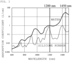
- the absorption rate of near-infrared light changes according to the wavelength and the substance (see FIG. 1 ). It can be seen that the infrared absorption rate of water greatly changes according to the wavelength in the near-infrared region.
- the lumen of the blood vessel model is often filled with a liquid in order to imitates blood, and as such a liquid, an aqueous solution in which a lubricating component is mixed as necessary with a liquid containing water as a main component similarly to blood is generally used.
- an aqueous solution in which a lubricating component is mixed as necessary with a liquid containing water as a main component similarly to blood is generally used.
- 1450 nm was selected as a wavelength at which the absorption rate of water was significantly high in the near-infrared region and which was easily differentiated from the absorption rate of air, silicone rubber, or the like, and observation of the blood vessel model and the catheter inserted into the blood vessel model was performed.
- FIG. 2 illustrates a structure of an observation device 10.
- Reference sign 1 in the drawing denotes a catheter.
- the catheter 1 includes a sheath 2 and wires 3 inserted into the sheath 2.
- Reference sign 5 denotes a blood vessel model, and a lumen of the blood vessel model 5 is filled with a lubricating liquid 6.
- the lubricating liquid may be circulated to impart fluidity to the lubricating liquid.
- the periphery of the blood vessel model 5 is filled with an immersion liquid 7 containing no lubricating component.
- the observation device 10 includes a first near-infrared light source 11, a light amount adjustment device 13, a first near-infrared camera 15, and a display 17.
- the blood vessel model is made of silicone rubber provided by FAIN-Biomedical Inc., and has a membrane thickness of 0.3 mm to 3.0 mm and a lumen of 1 mm to 15 mm.
- the lumen region of the blood vessel model is filled with a lubricating liquid in which a lubricating component is mixed with water.
- This lubricating liquid is a substance having near-infrared light absorption characteristics different from the constituent material of the blood vessel model.
- an Excelsior microcatheter manufactured by Stryker Japan K.K. was used as a catheter.
- As the wires a GDC coil manufactured by Stryker Japan K.K. was used.
- an infrared illumination (model number: TH2-100X100IR145) manufactured by CCS Inc. was used.
- a power supply (model number: PD-3024) having a function of adjusting an output of the light source 11, that is, a light amount of near-infrared light emitted from the light source 11 was used.
- a near-infrared camera (model number: ABA-013VIR) manufactured by Aval Data Corporation and a polarization camera (model number: XCG-CP510) manufactured by Sony Corporation were used, and as the camera lens, a near-infrared compatible lens (model number: LM35HC-SW and model number: LM35HC-VIS-SW) manufactured by Kowa Optronics Co., Ltd. was used.
- an observation target is set between the light source 11 and the camera 15.
- Near-infrared light having a wavelength of 1450 nm is emitted from the light source 11, and the light amount thereof is adjusted by the light amount adjustment device 13.
- the near-infrared light emitted from the light source 11 to the blood vessel model 5 transmits through the blood vessel model 5, is received by the camera 15, and an image thereof is displayed on the display 17.
- FIG. 3(A) illustrates an image obtained by monochromatizing an observation image of a blood vessel model and a catheter inserted into said blood vessel model observed by a visible light optical camera in the above setting.
- FIG. 3(B) illustrates an observation image of the blood vessel model and the catheter inserted into the blood vessel model of FIG. 3(A) which were observed by the camera 15 (the diaphragm of the lens attached to the camera was set to F2.8) using the light source 11 of 1450 nm (the light amount was set to the maximum in the light amount adjustment device attached to the light source).
- the distal end positions of the wires disposed inside the catheter can be observed from reference signs 6, 7, 8, and the like in FIG. 3(B) .
- a structure such as a metal mesh incorporated in the catheter could also be observed via fluoroscopy.
- the state and internal structure in the sheath of the catheter cannot be confirmed by the visible light observation illustrated in FIG. 3(A) (reference sign 3 is an appearance image of an X-ray opaque marker exposed on the surface of the sheath).
- reference sign 3 is an appearance image of an X-ray opaque marker exposed on the surface of the sheath.
- the lumen region, the wall cross-sectional region, and the region around the blood vessel of the blood vessel model appear to be the same color (transparent).
- each of the above regions can be clearly identified by shading.
- the reflected image appears as a shading distribution on the lumen region, visibility of the lumen region decreases. Compared with the method of visualizing the wall cross-sectional area of the present invention, it is not preferable.
- the use of the near-infrared light does not hinder the operation of the operator at all. In other words, even if the light amount of the near-infrared light source is arbitrarily adjusted so as to obtain the optimum observation condition, no burden is put on the operator.
- the water-soluble polymer was dissolved in the lubricating liquid 6 filling the inside of the blood vessel model 5 and the immersion liquid 7 filling the periphery of the blood vessel model 5.
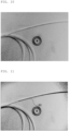
- Such a water-soluble polymer is considered to be particles having a diameter of several nm in an aqueous solution, and causes Rayleigh scattering as illustrated in FIG. 4 .
- the near-infrared light from the light source 11 are scattered in the liquid, and the observation target is efficiently irradiated with the near-infrared light.
- each part of the obtained observation image was a more planar (2D) image close to the observation image by X-ray.
- This effect was particularly remarkably confirmed in the wall cross-sectional region of the blood vessel model, and when a liquid that causes Rayleigh scattering was used, the wall cross-sectional region was observed as a region of uniform color without pattern.
- an image of the surrounding environment or the like was projected on the wall cross-sectional region to generate shading or a pattern, and there were cases in which the region was observed slightly three-dimensionally.
- the infrared absorption rate by water is higher than that in the region having a wavelength of 780 nm to 1200 nm.
- the infrared ray absorption characteristics of silicone rubber vary depending on the type, but silicone rubber (model number: SYLGARD 182 manufactured by The Dow Chemical Company) having the characteristics illustrated in FIG. 1 is lower than water in a main wavelength region of near-infrared light (in particular, when the wavelength is 1200 nm, the absorptivity is close to that of water, and when the wavelength is 1450 nm, the absorptivity is significantly higher than that of water).
- the near-infrared absorption rate of water is lower than the near-infrared absorption rate of the catheter or the wires
- by using near-infrared light having a shorter wavelength a wavelength of 1200 nm or the like in the configuration of the present embodiment
- increasing the light amount by adjusting the light source using the light amount adjustment device attached to the camera, or the like, or adjusting the shading balance of the observation image with the camera-attached image processing device, the degree of visualization of the lumen region on the observation image was weakened or completely disappeared without almost affecting the fluoroscopic image of the catheter.
- images at the time of administration and at the time of non-administration of a contrast medium in an X-ray observation image at the time of actual surgery can be easily and instantaneously selectively reproduced without performing a physical operation on an observation target such as administration of a contrast medium.
- FIG. 5(B) is an observation image obtained when the diaphragm of the accompanying lens of the camera 15 was set to F2.8 using the light source 11 of 1450 nm (the light amount was set to the maximum by the adjustment device accompanying the light source). Under this condition, the lumen region (wall cross-sectional region) of the blood vessel model is visualized in a distinguishable state together with the fluoroscopic image of the catheter.
- FIG. 5(C) illustrates an observation image obtained when the diaphragm of the accompanying lens of the camera 15 was set to F1.8 while the same light source 11 was used.
- FIG. 5(A) illustrates an observation image obtained when the diaphragm of the accompanying lens of the camera 15 was set to F5.0 while the same light source 11 was used.
- the entire observation image becomes dark, and it is difficult to visually recognize the state inside the catheter, which is not appropriate as the observation condition.
- the conditions of the amount of light that can be obtained in FIGS. 5(B) and 5(C) are changed.
- the diameter of the blood vessel model is large, or in a case where the depth of the immersion liquid 7 around the blood vessel model is large, at a wavelength of 1300 nm to 1550 nm, the amount of infrared rays absorbed by water is excessively large, and the obtained image becomes dark as a whole, so that a high light amount was required for the light source.
- near-infrared light having a wavelength shorter than 1300 nm near-infrared light having a wavelength of 780 nm to 1250 nm, etc.
- it is effective to create a state suitable for near-infrared fluoroscopic observation and near-infrared spectroscopic observation by adjusting the light amount of near-infrared light so that the contrast value of only the region containing water decreases.
- observation conditions such as a light amount and a wavelength of a light source while observing an image reflected on a display each time according to a catheter or a blood vessel model to be used.
- the light amount and the focus may be adjusted according to the distance from the light source to the observation target.
- the observation image of the blood vessel model that can identify the lumen region of the blood vessel model and the fluoroscopic image of the catheter can be simultaneously observed.
- the material forming the blood vessel model and/or the liquid filling the blood vessel model by mixing particles interfering with near-infrared light in the material forming the blood vessel model and/or the liquid filling the blood vessel model, it is also possible to enhance the impermeability of the portion where the particles exist at the time of observation with near-infrared light and forcibly visualize the region including the particles, that is, the lumen region of the blood vessel model.
- the particles that interfere with near-infrared light particles that absorb near-infrared light, particles that scatter near-infrared light, or particles that reflect near-infrared light can be used, and for example, aluminum fine particles, India ink (carbon-based fine particles), or the like can be used.
- the light source is not particularly limited as long as it can emit near-infrared light having an intensity capable of observing a fluoroscopic image of the catheter. From the viewpoint of near-infrared spectroscopic observation, it is possible to adjust the shading balance of each part of the observation target by allowing a plurality of light sources having different wavelengths to coexist or preparing a light source having a variable wavelength.
- the selection of the wavelength can also be performed on the camera side.
- a filter having wavelength selectivity can be installed in front of the camera, or a wavelength can be selected at the time of image processing after light is collected by the camera.
- an image can be formed by switching the wavelengths. Furthermore, it is also possible to simultaneously form an image corresponding to each wavelength by simultaneously emitting light from light sources having different wavelengths and preparing a camera and a display thereof corresponding to each wavelength.
- the wavelength can be selected so as to generate an appropriate shade according to the diameter of the blood vessel model and the depth of the surrounding immersion liquid.
- a wavelength exhibiting optimal absorption characteristics or transmission characteristics can be selected according to the type and material of the catheter to be used.
- the light source it is preferable to employ a surface light source that uniformly irradiates a desired region of the blood vessel model to be observed with near-infrared light.
- a parallel light source may be used for the purpose of clearly observing the outline of the observation target, or a diffusion light source may be used for the purpose of facilitating the fluoroscopic observation by irradiating the observation target with light from multiple directions.
- only a partial region of the observation target can be observed using a line light source or a point light source, or a desired region of the blood vessel model can be uniformly irradiated with near-infrared light from the line light source or the point light source via the light diffusion circuit.
- the light source can also irradiate the observation target from a plurality of directions.
- near-infrared light have low permeability to metal
- a platinum X-ray opaque marker is partially attached to a stainless delivery wire of the aneurysm embolization coil, it is not possible to identify them.
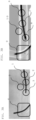
- the inventors have found out utilization of the property of near-infrared light which shows different reflectivity depending on the type and wavelength of the metallic material. It has been found that an observation image in which a structure made of a different metal material can be identified as illustrated in FIG. 6 , can be obtained by performing observation using reflection of near-infrared light in combination.
- reference sign 20 denotes the above-mentioned stainless steel delivery wire
- reference sign 30 denotes the above-mentioned platinum X-ray opaque marker.
- a second light source for generating reflection of near-infrared light is arranged in a side direction (a direction orthogonal to the axis of the first light source and the camera used for near-infrared fluoroscopic observation, or obliquely upward) of the blood vessel model, and the blood vessel model is irradiated with near-infrared light.
- a third light source may be added to additionally emit light from a direction different from that of the first and second light sources.
- the wavelengths of the first light source, the second light source, and the third light source can be arbitrarily selected, but in order to suppress the chromatic aberration, it is preferable to make the wavelengths of the respective light sources the same.
- the camera is not particularly limited as long as it can receive near-infrared light from the light source.
- a plurality of cameras can be adopted according to the light source.
- the display images the output from the camera.
- a light source or a light amount adjustment device attached to the camera is disposed at a position where the light amount can be adjusted while the display is visually recognized so that the light amount incident on the camera can be adjusted while the image on the display is visually recognized.
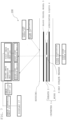
- FIG. 7 illustrates a configuration of an image capturing device 100.
- the same elements as those in FIG. 2 are denoted by the same reference signs, and the description thereof will be omitted.
- the first near-infrared light having a wavelength of 940 nm is emitted from the first light source of the image capturing device 100, and is polarized in the first direction in a first polarization plate 103.
- the first near-infrared light thus polarized are received by a first light reception unit 111.
- the second near-infrared ray having a wavelength of 850 nm is emitted from the second light source 105, and is polarized in the second direction in a second polarization plate 107.
- the second near-infrared light thus polarized are reflected by the observation target and received by a second light reception unit 112.
- the first image formation unit 121 forms a first image by first near-infrared light received by the first light reception unit 111.
- the first image formation unit 121 includes a gray-scaled image generation unit, and the first image is gray-scaled.
- FIG. 8 illustrates an example of the first image.
- the second image formation unit 122 forms a second image by second near-infrared light received by the second light reception unit 112.
- the second image formation unit 122 includes a gray-scaled image generation unit, and the second image is gray-scaled.
- FIG. 9 illustrates an example of the second image.
- the color tone of the second image is inverted in an image inversion unit 128.
- FIG. 10 illustrates an image 2-1 thus inverted.
- the image 2-1 and the first image are synthesized in the image synthesis unit 130.
- the values of the corresponding pixels in both images are numerically multiplied. As a result, black is more emphasized on the black side, and white is more emphasized on the white side.
- FIG. 11 An image synthesized in this manner is illustrated in FIG. 11 .
- the position of the X-ray opaque marker is emphasized by performing density correction.
- FIG. 13 illustrates an observation device 200 according to another embodiment.
- the same elements as those in FIG. 7 are denoted by the same reference signs, and the description thereof will be omitted.
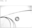
- the observation device 200 in FIG. 13 includes a background image storage unit 210, an image evaluation unit 220, and a guidance generation unit 221.
- the background image storage unit 210 stores images of bones and other tissues, and this image can be displayed together with the composite image by the image synthesis unit 130.
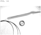
- the image evaluation unit 220 evaluates the composite image illustrated in FIG. 12 using, for example, a photoelastic stress observation method or AI. As illustrated in FIG. 14 , when the stress generated in the blood vessel model is evaluated by the photoelastic stress observation method, the guidance display unit 221 displays the stress distribution as color (gradation) information superimposed on the composite image as the guidance. At the same time, text information can be also displayed.
- a photoelastic stress observation method or AI As illustrated in FIG. 14 , when the stress generated in the blood vessel model is evaluated by the photoelastic stress observation method, the guidance display unit 221 displays the stress distribution as color (gradation) information superimposed on the composite image as the guidance. At the same time, text information can be also displayed.
- blood vessels are only visualized for a few seconds because the administered contrast medium flows away by the blood flow. Furthermore, there is an upper limit to the amount of the contrast medium used due to toxicity, and the contrast medium cannot be administered repeatedly. For this reason, a method (blood vessel roadmap method) is used in which a blood vessel visualization image at the moment when a contrast medium is administered is stored as a still image and superimposed on an observation image in which only a catheter is visualized.
- the above-described blood vessel road map method can be reproduced by performing image processing in which after a still image in a state in which a blood vessel lumen portion is visualized is stored, an image of the blood vessel lumen portion is eliminated by changing observation conditions to make only a catheter in a visualized state, and the still images are superimposed and presented as necessary.
- a hardware interface such as a foot pedal and a joystick are further provided in the observation device of the present invention so that various operations associated with the image processing can be performed in a form similar to the actual catheter intravascular surgery.
- a cross-linked soft polymer material such as silicone rubber, urethane rubber, soft polyvinyl chloride, and a soft photocurable resin, a hard polymer material such as an acrylic resin and a hard photocurable resin, or a material obtained by combining these materials and formed of a material that transmits near-infrared light can be used.
- a cross-linked soft polymer material such as silicone rubber, urethane rubber, soft polyvinyl chloride, and a soft photocurable resin
- a hard polymer material such as an acrylic resin and a hard photocurable resin
- a material obtained by combining these materials and formed of a material that transmits near-infrared light can be used.
- the lumen of the blood vessel model can be filled with a lubricating liquid containing water as a main component, or the lumen can be filled with air after the lubricating liquid is applied to the lumen surface of the blood vessel model.
- a blood vessel model having a membrane-like structure similar to that of a biological blood vessel hereinafter, referred to as a "membranous blood vessel model”
- a blood vessel model in which a cavity simulating a blood vessel lumen is formed inside a block body such as a rectangular parallelepiped, a cylinder, or a sphere
- a block-shaped blood vessel model hereinafter, referred to as a block-shaped blood vessel model
- a liquid, a gas, or a solid in particular, a gel-like solid
- a liquid, a gas, or a solid can be selectively disposed in each of the lumen region and the peripheral region of the blood vessel model depending on the situation (for example, water may be placed in the lumen region and water or air may be placed in the surrounding region).
- water may be placed in the lumen region and water or air may be placed in the surrounding region.
- the membranous blood vessel model not only the lumen region of the blood vessel model but also the wall cross-sectional region of the blood vessel model can be visualized so as to be distinguishable.
- various substances can be selectively disposed in the lumen region according to the situation.
- various materials such as soft materials such as silicone rubber, urethane rubber, soft polyvinyl chloride and soft photocurable resin, gels made of polyvinyl alcohol and the like, acrylic resin and hard photocurable resin can be used as long as the material has near-infrared light permeability.
- the polymer material has permeability to visible light so that an operator can visually observe the blood vessel model in a state of being irradiated with near-infrared light.
- crosslinked polymer material examples include crosslinked soft polymer materials such as silicone rubber, urethane rubber, soft polyvinyl chloride, and soft photocurable resin, hard polymer materials such as acrylic resin and hard photocurable resin, and materials obtained by combining these materials.
- the material for forming the blood vessel model, the liquid filling the lumen portion of the blood vessel model, and the like may be colored with a dye or the like that can be identified in a visible light region. Since most of the dyes used in the visible light region exhibit high permeability in the near-infrared region, they hardly affect the near-infrared spectroscopic observation image, and an image observation condition in the visible light region and an image observed in the near-infrared region can be set separately.
- a blood vessel model can also be formed from a gel substance such as polyvinyl alcohol. Since the blood vessel model made of polyvinyl alcohol has high lubricity due to its physical properties, the material filled in the lumen of the blood vessel model may be only water or air. Of course, addition of a chemical agent for enhancing lubricity such as a surfactant is not hindered.
- a lesion model simulating a thrombus or a plaque can be attached to the blood vessel model in advance or can be movably installed.
- the first near-infrared light transmitted through the observation target and the second near-infrared light reflected by the observation target are simultaneously received by using one light reception unit, and an image can be directly formed without performing any calculation based on the received light.
- the lens provided in the light reception unit has a focus shift correction function.
- one light reception unit it is also possible to receive the first near-infrared light transmitted through the observation target and the second near-infrared light reflected by the observation target with a time difference, and synthesize them by calculating images generated from respective lights.
- the color tone of the second image generated from the second near-infrared light can be inverted, and this inverted second image and the first image generated from the first near-infrared light can be synthesized by calculating those images.
Landscapes
- Engineering & Computer Science (AREA)
- Health & Medical Sciences (AREA)
- Physics & Mathematics (AREA)
- Life Sciences & Earth Sciences (AREA)
- General Physics & Mathematics (AREA)
- General Health & Medical Sciences (AREA)
- Medical Informatics (AREA)
- Theoretical Computer Science (AREA)
- Chemical & Material Sciences (AREA)
- Pathology (AREA)
- Business, Economics & Management (AREA)
- Spectroscopy & Molecular Physics (AREA)
- Educational Technology (AREA)
- Educational Administration (AREA)
- Radiology & Medical Imaging (AREA)
- Mathematical Analysis (AREA)
- Computational Mathematics (AREA)
- Mathematical Optimization (AREA)
- Pure & Applied Mathematics (AREA)
- Mathematical Physics (AREA)
- Surgery (AREA)
- Heart & Thoracic Surgery (AREA)
- Animal Behavior & Ethology (AREA)
- Molecular Biology (AREA)
- Algebra (AREA)
- Veterinary Medicine (AREA)
- Medicinal Chemistry (AREA)
- Public Health (AREA)
- Biophysics (AREA)
- Biomedical Technology (AREA)
- Nuclear Medicine, Radiotherapy & Molecular Imaging (AREA)
- Multimedia (AREA)
- Signal Processing (AREA)
- Biochemistry (AREA)
- Immunology (AREA)
- Analytical Chemistry (AREA)
- Vascular Medicine (AREA)
- Computer Vision & Pattern Recognition (AREA)
- Human Computer Interaction (AREA)
- Entrepreneurship & Innovation (AREA)
Applications Claiming Priority (2)
| Application Number | Priority Date | Filing Date | Title |
|---|---|---|---|
| JP2022111530 | 2022-07-12 | ||
| PCT/JP2023/025803 WO2024014496A1 (ja) | 2022-07-12 | 2023-07-12 | 血管モデルの観察装置及びその方法 |
Publications (2)
| Publication Number | Publication Date |
|---|---|
| EP4557263A1 true EP4557263A1 (de) | 2025-05-21 |
| EP4557263A4 EP4557263A4 (de) | 2026-05-20 |
Family
ID=89536766
Family Applications (1)
| Application Number | Title | Priority Date | Filing Date |
|---|---|---|---|
| EP23839668.3A Pending EP4557263A4 (de) | 2022-07-12 | 2023-07-12 | Vorrichtung und verfahren zur beobachtung eines blutgefässmodells |
Country Status (8)
| Country | Link |
|---|---|
| US (1) | US20260129277A1 (de) |
| EP (1) | EP4557263A4 (de) |
| JP (2) | JP7636059B2 (de) |
| KR (1) | KR20250016300A (de) |
| CN (1) | CN119278472A (de) |
| AU (1) | AU2023307403A1 (de) |
| CA (1) | CA3260636A1 (de) |
| WO (1) | WO2024014496A1 (de) |
Families Citing this family (2)
| Publication number | Priority date | Publication date | Assignee | Title |
|---|---|---|---|---|
| JP7636059B2 (ja) * | 2022-07-12 | 2025-02-26 | ファイン・バイオメディカル有限会社 | 血管モデルの観察装置及びその方法 |
| WO2025263635A1 (ja) * | 2024-06-20 | 2025-12-26 | ファイン・バイオメディカル有限会社 | 観察装置、観察方法、カセット及びプレート |
Family Cites Families (7)
| Publication number | Priority date | Publication date | Assignee | Title |
|---|---|---|---|---|
| JP2012147279A (ja) | 2011-01-13 | 2012-08-02 | Spectr Design Kk | 近赤外撮影装置 |
| EP2821467B1 (de) | 2012-02-24 | 2018-02-14 | Fain-Biomedical Inc. | Verwendung eines schmierfähigkeits-regulierungsmittels für siliconoberflächen |
| US9558678B1 (en) * | 2014-11-20 | 2017-01-31 | Michael E. Nerney | Near-infrared imager training device |
| JP6061318B1 (ja) | 2016-03-09 | 2017-01-18 | 国立大学法人高知大学 | 穿刺練習具 |
| JPWO2018154625A1 (ja) * | 2017-02-21 | 2019-12-12 | 国立研究開発法人産業技術総合研究所 | 撮像装置、撮像システム、及び撮像方法 |
| JP7755640B2 (ja) * | 2021-03-29 | 2025-10-16 | テルモ株式会社 | プログラム、画像処理方法及び画像処理装置 |
| JP7636059B2 (ja) * | 2022-07-12 | 2025-02-26 | ファイン・バイオメディカル有限会社 | 血管モデルの観察装置及びその方法 |
-
2023
- 2023-07-12 JP JP2024533745A patent/JP7636059B2/ja active Active
- 2023-07-12 CA CA3260636A patent/CA3260636A1/en active Pending
- 2023-07-12 KR KR1020247042957A patent/KR20250016300A/ko active Pending
- 2023-07-12 AU AU2023307403A patent/AU2023307403A1/en active Pending
- 2023-07-12 CN CN202380042858.1A patent/CN119278472A/zh active Pending
- 2023-07-12 EP EP23839668.3A patent/EP4557263A4/de active Pending
- 2023-07-12 US US18/871,049 patent/US20260129277A1/en active Pending
- 2023-07-12 WO PCT/JP2023/025803 patent/WO2024014496A1/ja not_active Ceased
-
2025
- 2025-02-05 JP JP2025017972A patent/JP7840081B2/ja active Active
Also Published As
| Publication number | Publication date |
|---|---|
| EP4557263A4 (de) | 2026-05-20 |
| KR20250016300A (ko) | 2025-02-03 |
| WO2024014496A1 (ja) | 2024-01-18 |
| JP7636059B2 (ja) | 2025-02-26 |
| US20260129277A1 (en) | 2026-05-07 |
| AU2023307403A1 (en) | 2025-02-06 |
| JP2025069402A (ja) | 2025-04-30 |
| JP7840081B2 (ja) | 2026-04-03 |
| CA3260636A1 (en) | 2025-06-13 |
| CN119278472A (zh) | 2025-01-07 |
| JPWO2024014496A1 (de) | 2024-01-18 |
Similar Documents
| Publication | Publication Date | Title |
|---|---|---|
| JP7840081B2 (ja) | 血管モデルの観察装置及びその方法 | |
| US8948851B2 (en) | Method and apparatus for depth-resolved fluorescence, chromophore, and oximetry imaging for lesion identification during surgery | |
| JP5489336B2 (ja) | 顕微鏡システムおよび顕微鏡システムの作動方法ならびに外科顕微鏡および外科顕微鏡の作動方法 | |
| KR101763833B1 (ko) | 임상 영상 상에 강화된 영상화 데이터를 표시하기 위한 방법 및 장치 | |
| US20030139650A1 (en) | Endoscope | |
| EP3616596B1 (de) | Mikroskop und verfahren mit pseudo-farbbilddaten | |
| CN114298980A (zh) | 一种图像处理方法、装置及设备 | |
| JP2008522761A (ja) | 規準化された蛍光又は生物発光撮像のためのシステムと方法 | |
| JP2008183394A (ja) | 照明の均一度を向上させた光学診断装置 | |
| US20160310007A1 (en) | Infrared light imaging apparatus | |
| JP6319449B2 (ja) | イメージング装置 | |
| CN108366717A (zh) | 内窥镜装置 | |
| JP2018134413A (ja) | イメージング装置 | |
| JP2002263091A (ja) | 立体x線透視法と立体x線透視のためのx線バルブ | |
| JPWO2024014496A5 (de) | ||
| KR101594523B1 (ko) | 가시광 광학영상 및 비가시광 형광영상의 동시구현이 가능한 광대역 영상 획득투사장치 | |
| EP2147635B1 (de) | Vorrichtung und Verfahren für die Beobachtung eines Gegenstandes | |
| JP7800580B2 (ja) | 治療支援システムおよびレーザ出力方法 | |
| JP7803616B1 (ja) | 観察装置及び観察方法 | |
| JP2025033588A (ja) | 血管モデルの観察装置及びその方法 | |
| CN108836506A (zh) | 一种用于手术的不可见光显示设备和光学指导系统 | |
| US20250204851A1 (en) | Imaging apparatus and method for detecting blood vessels under skin using transmissive light sources | |
| US10873710B2 (en) | IR/NIR imaging with discrete scale comparator objects | |
| JPWO2025263635A5 (de) | ||
| US20100067011A1 (en) | Ambient light reduction for optical tomography |
Legal Events
| Date | Code | Title | Description |
|---|---|---|---|
| STAA | Information on the status of an ep patent application or granted ep patent |
Free format text: STATUS: THE INTERNATIONAL PUBLICATION HAS BEEN MADE |
|
| PUAI | Public reference made under article 153(3) epc to a published international application that has entered the european phase |
Free format text: ORIGINAL CODE: 0009012 |
|
| STAA | Information on the status of an ep patent application or granted ep patent |
Free format text: STATUS: REQUEST FOR EXAMINATION WAS MADE |
|
| 17P | Request for examination filed |
Effective date: 20241127 |
|
| AK | Designated contracting states |
Kind code of ref document: A1 Designated state(s): AL AT BE BG CH CY CZ DE DK EE ES FI FR GB GR HR HU IE IS IT LI LT LU LV MC ME MK MT NL NO PL PT RO RS SE SI SK SM TR |
|
| DAV | Request for validation of the european patent (deleted) | ||
| DAX | Request for extension of the european patent (deleted) |