EP4556155A1 - Welding jig and welding device - Google Patents
Welding jig and welding device Download PDFInfo
- Publication number
- EP4556155A1 EP4556155A1 EP23869659.5A EP23869659A EP4556155A1 EP 4556155 A1 EP4556155 A1 EP 4556155A1 EP 23869659 A EP23869659 A EP 23869659A EP 4556155 A1 EP4556155 A1 EP 4556155A1
- Authority
- EP
- European Patent Office
- Prior art keywords
- frame
- covering member
- negative pressure
- pressure suction
- welding fixture
- Prior art date
- Legal status (The legal status is an assumption and is not a legal conclusion. Google has not performed a legal analysis and makes no representation as to the accuracy of the status listed.)
- Pending
Links
Images







Classifications
-
- B—PERFORMING OPERATIONS; TRANSPORTING
- B23—MACHINE TOOLS; METAL-WORKING NOT OTHERWISE PROVIDED FOR
- B23K—SOLDERING OR UNSOLDERING; WELDING; CLADDING OR PLATING BY SOLDERING OR WELDING; CUTTING BY APPLYING HEAT LOCALLY, e.g. FLAME CUTTING; WORKING BY LASER BEAM
- B23K37/00—Auxiliary devices or processes, not specially adapted for a procedure covered by only one of the other main groups of this subclass
- B23K37/04—Auxiliary devices or processes, not specially adapted for a procedure covered by only one of the other main groups of this subclass for holding or positioning work
- B23K37/0426—Fixtures for other work
- B23K37/0435—Clamps
- B23K37/0443—Jigs
-
- B—PERFORMING OPERATIONS; TRANSPORTING
- B23—MACHINE TOOLS; METAL-WORKING NOT OTHERWISE PROVIDED FOR
- B23K—SOLDERING OR UNSOLDERING; WELDING; CLADDING OR PLATING BY SOLDERING OR WELDING; CUTTING BY APPLYING HEAT LOCALLY, e.g. FLAME CUTTING; WORKING BY LASER BEAM
- B23K37/00—Auxiliary devices or processes, not specially adapted for a procedure covered by only one of the other main groups of this subclass
-
- H—ELECTRICITY
- H01—ELECTRIC ELEMENTS
- H01M—PROCESSES OR MEANS, e.g. BATTERIES, FOR THE DIRECT CONVERSION OF CHEMICAL ENERGY INTO ELECTRICAL ENERGY
- H01M50/00—Constructional details or processes of manufacture of the non-active parts of electrochemical cells other than fuel cells, e.g. hybrid cells
- H01M50/10—Primary casings; Jackets or wrappings
- H01M50/102—Primary casings; Jackets or wrappings characterised by their shape or physical structure
- H01M50/103—Primary casings; Jackets or wrappings characterised by their shape or physical structure prismatic or rectangular
-
- H—ELECTRICITY
- H01—ELECTRIC ELEMENTS
- H01M—PROCESSES OR MEANS, e.g. BATTERIES, FOR THE DIRECT CONVERSION OF CHEMICAL ENERGY INTO ELECTRICAL ENERGY
- H01M50/00—Constructional details or processes of manufacture of the non-active parts of electrochemical cells other than fuel cells, e.g. hybrid cells
- H01M50/10—Primary casings; Jackets or wrappings
- H01M50/147—Lids or covers
- H01M50/148—Lids or covers characterised by their shape
- H01M50/15—Lids or covers characterised by their shape for prismatic or rectangular cells
-
- H—ELECTRICITY
- H01—ELECTRIC ELEMENTS
- H01M—PROCESSES OR MEANS, e.g. BATTERIES, FOR THE DIRECT CONVERSION OF CHEMICAL ENERGY INTO ELECTRICAL ENERGY
- H01M50/00—Constructional details or processes of manufacture of the non-active parts of electrochemical cells other than fuel cells, e.g. hybrid cells
- H01M50/10—Primary casings; Jackets or wrappings
- H01M50/147—Lids or covers
- H01M50/166—Lids or covers characterised by the methods of assembling casings with lids
- H01M50/169—Lids or covers characterised by the methods of assembling casings with lids by welding, brazing or soldering
-
- B—PERFORMING OPERATIONS; TRANSPORTING
- B23—MACHINE TOOLS; METAL-WORKING NOT OTHERWISE PROVIDED FOR
- B23K—SOLDERING OR UNSOLDERING; WELDING; CLADDING OR PLATING BY SOLDERING OR WELDING; CUTTING BY APPLYING HEAT LOCALLY, e.g. FLAME CUTTING; WORKING BY LASER BEAM
- B23K2101/00—Articles made by soldering, welding or cutting
- B23K2101/006—Vehicles
-
- B—PERFORMING OPERATIONS; TRANSPORTING
- B23—MACHINE TOOLS; METAL-WORKING NOT OTHERWISE PROVIDED FOR
- B23K—SOLDERING OR UNSOLDERING; WELDING; CLADDING OR PLATING BY SOLDERING OR WELDING; CUTTING BY APPLYING HEAT LOCALLY, e.g. FLAME CUTTING; WORKING BY LASER BEAM
- B23K2101/00—Articles made by soldering, welding or cutting
- B23K2101/36—Electric or electronic devices
-
- Y—GENERAL TAGGING OF NEW TECHNOLOGICAL DEVELOPMENTS; GENERAL TAGGING OF CROSS-SECTIONAL TECHNOLOGIES SPANNING OVER SEVERAL SECTIONS OF THE IPC; TECHNICAL SUBJECTS COVERED BY FORMER USPC CROSS-REFERENCE ART COLLECTIONS [XRACs] AND DIGESTS
- Y02—TECHNOLOGIES OR APPLICATIONS FOR MITIGATION OR ADAPTATION AGAINST CLIMATE CHANGE
- Y02E—REDUCTION OF GREENHOUSE GAS [GHG] EMISSIONS, RELATED TO ENERGY GENERATION, TRANSMISSION OR DISTRIBUTION
- Y02E60/00—Enabling technologies; Technologies with a potential or indirect contribution to GHG emissions mitigation
- Y02E60/10—Energy storage using batteries
Definitions
- the present application relates to the technical field of battery production, and in particular to a welding fixture and a welding device.
- a battery is composed of a case and a battery cell or a battery module accommodated in the case.
- the case typically comprises a frame and a covering member.
- the covering member is first welded to the frame.
- the covering member has an uneven structure on the surface, the uneven structure on the surface of the covering member is easy to be crushed by a pressing plate in a conventional fixing method where the covering member is pressed against the frame.
- the covering member is a water cooling plate
- the water channels of the water cooling plate are easy to be crushed by the pressing plate, causing scrapping of the water cooling plate. This results in high production scrap rate and high production cost.
- an objective of the present application is to provide a welding fixture and a welding device, which can reduce the risk of damage to a covering member.
- the present application provides a welding fixture configured to fix a frame and a covering member which covers a first opening of the frame, the welding fixture comprising a base, a frame positioning mechanism and a negative pressure suction mechanism, wherein the base comprises a placement region in which the frame is placed; the frame positioning mechanism is arranged on the base and configured to position the frame; and the negative pressure suction mechanism is arranged in the placement region and configured to generate negative pressure to suck the covering member so as to press the covering member against the frame.
- the negative pressure suction mechanism is located on an inner side of the fixed frame, the covering member is placed on the frame, a bottom surface of the covering member is sucked by means of the negative pressure suction mechanism, the covering member is closely attached to a welding region of the frame under the action of suction force, and the suction force of the negative pressure suction mechanism can uniformly act on a surface of the covering member, thus reducing the risk of damage to the covering member due to the excessively concentrated pressure.
- the negative pressure suction mechanism comprises first negative pressure suction units and second negative pressure suction units, the number of the first negative pressure suction units being greater than that of the second negative pressure suction units, and the suction area of the first negative pressure suction unit being smaller than that of the second negative pressure suction unit.
- the first negative pressure suction units are arranged at intervals around the center of the covering member so that the suction force from the first negative pressure suction units can act on all parts of the covering member; and the plurality of first negative pressure suction units apply smaller suction force to the covering member to allow the covering member to be in close contact with the welding region of the frame, and the second negative pressure suction units then apply larger suction force to the covering member to fix the covering member in position, thus reducing the risk of displacement of the covering member during welding.
- the plurality of first negative pressure suction units are arranged at intervals around the second negative pressure suction units.
- the first negative pressure suction units are closer to the covering member and the welding region of the frame than the second negative pressure suction units, and the portion of the covering member near the edge can be sucked by means of the plurality of first negative pressure suction units and pulled towards the welding region of the frame, so that the covering member is closely attached to the welding region of the frame, while the surface of the covering member that is in contact with the frame is also stressed uniformly, thus reducing the risk of partial tilt of the covering member.
- the first negative pressure suction unit is a bowl-shaped suction cup
- the second negative pressure suction unit is a square suction cup.
- the bowl-shaped suction cup when sucking the covering member, expels the air in the interior to reduce its own volume, so that the covering member is pulled towards the welding region of the frame to allow the covering member to be closely attached to the welding region of the frame, thus reducing the risk of partial tilt of the covering member.
- the square suction cup has a larger contact surface with the covering member and can provide larger suction force for the covering member, thus reducing the risk of displacement of the covering member during welding.
- the welding fixture further comprises a heating mechanism arranged in the placement region and configured to heat the covering member.
- the covering member after the covering member is placed on the frame, the covering member is heated by means of the heating mechanism, the covering member has volume expansion as it heats up, specifically, the edge of the covering member extends in its own width and length directions, and then the frame is welded to the volumetrically expanded covering member.
- the heating mechanism stops heating, and as the temperature of the covering member decreases, the covering member tends to shrink. Since the edge of the covering member has been welded to the frame, the shrinking force of the covering member acts on the central portion of the covering member to stretch the central portion of the covering member towards the edge of the covering member, so that the central portion of the covering member is flattened, thus improving the overall flatness of the covering member.
- the heating mechanism comprises a heating plate, which comprises an elastic insulation layer and an electric heating wire embedded in the elastic insulation layer and is configured to be attached to the covering member for heating the covering member.
- the elastic insulation layer is closely attached to the covering member in the form of surface contact, and the covering member is heated by the electric heating wire via the elastic insulation layer, so that the covering member can be heated uniformly.
- the elastic insulation layer is made of silica gel.
- silica gel is soft and not easy to scratch the covering member, and on the other hand, silica gel can deform depending on the shape of the surface of the covering member to allow itself to be completely attached to the covering member, so that the covering member can be heated uniformly.
- the heating mechanism comprises the plurality of heating plates arranged in the same plane and spaced apart from each other.
- the negative pressure suction mechanism comprises the second negative pressure suction unit and the plurality of first negative pressure suction units
- the plurality of heating plates are staggered with the second negative pressure suction unit and the plurality of first negative pressure suction units, so that the covering member can be heated uniformly while receiving the suction force uniformly at all parts.
- the heating mechanism further comprises a height-adjustable first holder arranged in the placement region and configured to support the heating plate.
- the first holder can adjust its height adapted to the frame that is fixed to the placement region, so that a top surface of the heating plate can be attached to the bottom surface of the covering member, which is convenient for the heating plate to heat the covering member.
- the heating mechanism further comprises a hot air blower configured to blow hot air to the covering member.
- the hot air blower can blow hot air to the surface of the covering member that is not attached to the heating plate, so that the covering member is heated and can be heated uniformly.
- the frame positioning mechanism comprises a first positioning mechanism comprising a positioning pin which extends in a thickness direction of the covering member and fits with a through hole in the frame to achieve positioning for the frame.
- the through hole in the frame fits with the positioning pin to restrict the movement of the frame in a second direction or in a third direction so as to provide initial positioning for the frame, and then the frame comes into contact with the placement region of the base.
- the frame positioning mechanism comprises a second positioning mechanism comprising a pressing member and a locking member, the pressing member being rotatably connected to the base and configured to switch between a pressing position and a release position, and the locking member being configured to lock the pressing member in the pressing position to allow the pressing member to press the frame against the base.
- the pressing member is turned over to press the frame against the base to restrict the movement of the frame in the first direction and further provide positioning for the frame placed in the placement region.
- the frame positioning mechanism comprises a third positioning mechanism comprising an inner holding member and an outer holding member, the inner holding member being configured to press the frame from the inner periphery of the frame, and the outer holding member being configured to press the frame from the outer periphery of the frame.
- the inner holding member and the outer holding member move towards the frame so as to clamp the frame, so that the frame is fixed in the placement region in position.
- the covering member is a water cooling plate.
- the present application provides a welding device, comprising a welding fixture according to the first aspect and a welding execution unit which is configured to weld the covering member to the frame.
- the terms “mount”, “connected”, “connect”, or “attach” should be interpreted in a broad sense unless explicitly defined and limited otherwise. For example, they may be a fixed connection, a detachable connection, or an integral connection; or may be a direct connection, an indirect connection by means of an intermediate medium, or internal communication between two elements.
- the specific meanings of the foregoing terms in the present application may be understood according to specific circumstances.
- a plurality of means two or more (including two), similarly, “a plurality of groups” means two or more groups (including two groups), and “a plurality of pieces” means two or more pieces (including two pieces).
- traction batteries are used increasingly widely.
- the traction batteries are not only used in energy storage power systems such as hydroelectric power plants, thermal power plants, wind power plants and solar power plants, but also widely used in electric transportation means such as electric bicycles, electric motorcycles, and electric vehicles and in many fields such as military equipment and aerospace.
- electric transportation means such as electric bicycles, electric motorcycles, and electric vehicles and in many fields such as military equipment and aerospace.
- the market demand for the traction batteries is also expanding.
- a battery mentioned in the present application refers to a single physical module comprising one or more battery cells to provide a higher voltage and capacity.
- the battery generally comprises a case for packaging one or more battery cells.
- the case can prevent liquid or other foreign matter from affecting charging or discharging of the battery cell(s).
- the case comprises a frame and a covering member, such as a water cooling plate, welded to the frame.
- the covering member is pressed against a welding region of the frame by means of a pressing plate, and the covering member having an uneven structure on the surface may be deformed or even damaged when being pressed by the pressing plate.
- the covering member is a water cooling plate
- the pressing plate when the pressing plate is pressed against the water cooling plate, the pressing plate is pressed against a bulging water channel of the water cooling plate, and with the small contact surface between the pressing plate and the water channel of the water cooling plate, the water channel of the water cooling plate is easy to be damaged by pressing, causing scrapping of the water cooling plate, resulting in high production scrap rate and high production cost.
- a negative pressure suction mechanism is provided in a placement region on a base where the frame is placed.
- the negative pressure suction mechanism can generate negative pressure to suck the covering member towards the frame to allow the covering member to be closely attached to the frame, and the suction force generated by the negative pressure mechanism can uniformly act on the sucked surface of the covering member, thus reducing the risk of damage to the covering member, increasing the production yield, and reducing the production cost.
- the welding fixture disclosed in the embodiments of the present application may be applicable to, but not limited to, a welding process for a case of a battery, and may also be applicable to a welding process for a case of other devices.
- the present application provides a welding fixture configured to fix a frame 1 and a covering member 2, the covering member 2 covering a first opening of the frame 1, the welding fixture comprising a base 3, a frame positioning mechanism 4 and a negative pressure suction mechanism 5.
- the base 3 comprises a placement region in which the frame 1 is placed.
- the frame positioning mechanism 4 is arranged on the base 3 and configured to position the frame 1.
- the negative pressure suction mechanism 5 is arranged in the placement region and configured to generate negative pressure to suck the covering member 2 so as to press the covering member 2 against the frame 1.
- the placement region may be a central region of a top surface of the base 3.
- the covering member 2 may be a water cooling plate.
- the covering member 2 may be a base plate of the case.
- the surface of the covering member 2 may be provided with a groove adapted to a battery cell.
- a plurality of negative pressure suction mechanisms 5 may be provided.
- the plurality of negative pressure suction mechanisms 5 may be arranged at intervals in the placement region, and the plurality of negative pressure suction mechanisms 5 may be arranged in a way of avoiding uneven parts of the surface of the covering member 2.
- the negative pressure suction mechanism 5 is located on an inner side of the fixed frame 1, the covering member 2 is placed on the frame 1, a bottom surface of the covering member 2 is sucked by means of the negative pressure suction mechanism 5, the covering member 2 is closely attached to a welding region of the frame 1 under the action of suction force, and the suction force of the negative pressure suction mechanism 5 can uniformly act on a surface of the covering member 2, thus reducing the risk of damage to the covering member 2 due to the excessively concentrated pressure.
- the negative pressure suction mechanism 5 comprises first negative pressure suction units 51 and second negative pressure suction units 52, the number of the first negative pressure suction units 51 being greater than that of the second negative pressure suction units 52, and the suction area of the first negative pressure suction unit 51 being smaller than that of the second negative pressure suction unit 52.
- the plurality of first negative pressure suction units 51 may be arranged around the second negative pressure suction units 52.
- One second negative pressure suction unit 52 may be provided.
- a plurality of (e.g., two, three, four, or five) second negative pressure suction units 52 may be provided.
- the plurality of first negative pressure suction units 51 can be arranged in a way of avoiding the water channel of the water cooling plate.
- the first negative pressure suction units 51 are arranged at intervals around the center of the covering member 2 so that suction force from the first negative pressure suction units 51 can act on all parts of the covering member 2; and the plurality of first negative pressure suction units 51 apply smaller suction force to the covering member 2 to allow the covering member 2 to be in close contact with the welding region of the frame 1, and the second negative pressure suction units 52 then apply larger suction force to the covering member 2 to fix the covering member 2 in position, thus reducing the risk of displacement of the covering member 2 during welding.
- the plurality of first negative pressure suction units 51 are arranged at intervals around the second negative pressure suction units 52.
- One second negative pressure suction unit 52 may be provided, and the second negative pressure suction unit 52 is arranged at a position directly facing the center of the covering member 2.
- a plurality of (e.g., two, three, four, or five) second negative pressure suction units 52 may be provided, and the plurality of second negative pressure suction units 52 are arranged at intervals surrounding the center of the covering member 2.
- the first negative pressure suction units 51 are closer to the covering member 2 and the welding region of the frame 1 than the second negative pressure suction unit 52, and the portion of the covering member 2 near the edge can be sucked by means of the plurality of first negative pressure suction units 51 and pulled towards the welding region of the frame 1, so that the covering member 2 is closely attached to the welding region of the frame 1, while the surface of the covering member 2 that is in contact with the frame 1 is stressed uniformly, thus reducing the risk of partial tilt of the covering member 2.
- the first negative pressure suction unit 51 is a bowl-shaped suction cup 511
- the second negative pressure suction unit 52 is a square suction cup 521.
- a suction cup is a component that expels the air or liquid in the interior so as to fix itself to a non-porous surface under atmospheric pressure or liquid pressure.
- the bowl-shaped suction cup 511 may be made of an elastic material, and after coming into contact with the covering member 2, the bowl-shaped suction cup 511 may be deformed depending on the shape of the bottom surface of the covering member 2 to allow itself to be attached to the bottom surface of the covering member 2, thus reducing the risk of leakage of the suction force to enable the bowl-shaped suction cup 511 to stably suck the covering member 2.
- the bowl-shaped suction cup 511 can be mounted in the placement region by means of a first mounting leg 512.
- the mounting leg may be provided with a plurality of bowl-shaped suction cups 511.
- the square suction cup 521 may be made of an elastic material, and after coming into contact with the covering member 2, the square suction cup 521 may be deformed depending on the shape of the bottom surface of the covering member 2 to allow itself to be attached to the bottom surface of the covering member 2, thus reducing the risk of leakage of the suction force to enable the square suction cup 521 to stably suck the covering member 2.
- the square suction cup 521 can be mounted in the placement region by means of a second mounting base 522.
- a top surface of the bowl-shaped suction cup 511 may exceed a top surface of the frame 1.
- the covering member 2 comes into contact with the top surface of the bowl-shaped suction cup 511, and then the air in the interior of the bowl-shaped suction cup 511 is drawn out by means of a vacuum cylinder to form local vacuum to suck the covering member 2.
- the bowl-shaped suction cup 511 shrinks to pull the covering member 2 towards the frame 1, so that the frame 1 is attached to the welding region of the frame 1, while the bottom surface of the covering member 2 comes into contact with the square suction cup 521, which is convenient for the square suction cup 521 to suck the covering member 2 to fix the covering member 2 in position.
- the bowl-shaped suction cup 511 When sucking the covering member 2, the bowl-shaped suction cup 511 expels the air in the interior to reduce its own volume, and then the covering member 2 is pulled towards the welding region of the frame 1 to allow the covering member 2 to be closely attached to the welding region of the frame 1, thus reducing the risk of partial tilt of the covering member 2.
- the square suction cup 521 has a larger contact surface with the covering member 2 and can provide larger suction force for the covering member 2, thus reducing the risk of displacement of the covering member 2 during welding.
- the welding fixture further comprises a heating mechanism 6.
- the heating mechanism 6 is arranged in the placement region and configured to heat the covering member 2.
- the heating mechanism 6 is located on the inner side of the frame 1 that is fixed in the placement region, and the bottom surface of the covering member 2 faces the heating mechanism 6.
- the heating mechanism 6 may comprise a heating plate 61 attached to the bottom surface of the covering member 2 and heating the covering member 2 uniformly.
- the heating mechanism 6 may comprise a heating lamp arranged at a distance from the bottom surface of the covering member 2 and heating the covering member 2 by thermal radiation.
- a second direction Y as shown is a length direction of the covering member 2.
- a third direction Z as shown is a width direction of the covering member.
- the covering member 2 After the covering member 2 is placed on the frame 1, the covering member 2 is heated by means of the heating mechanism 6, the covering member 2 has volume expansion as it heats up, specifically, the edge of the covering member 2 extends in its own width and length directions, and then the frame 1 is welded to the volumetrically expanded covering member 2. After the welding is completed, the heating mechanism 6 stops heating, and as the temperature of the covering member 2 decreases, the covering member 2 tends to shrink. Since the edge of the covering member 2 has been welded to the frame 1, the shrinkage force of the covering member 2 acts on the central portion of the covering member 2 to stretch the central portion of the covering member 2 towards the edge of the covering member 2, so that the central portion of the covering member 2 is flattened, thus improving the overall flatness of the covering member 2.
- the heating mechanism 6 comprises a heating plate 61.
- the heating plate 61 comprises an elastic insulation layer and an electric heating wire embedded in the elastic insulation layer, and the heating plate 61 is configured to be attached to the covering member 2 for heating the covering member 2.
- the material of the elastic insulation layer may be, but not limited to, engineering plastic, resin, rubber, silica gel, etc.
- the elastic insulation layer is closely attached to the covering member 2 in the form of surface contact, and the covering member 2 is heated by the electric heating wire via the elastic insulation layer, so that the covering member 2 can be heated uniformly.
- the elastic insulation layer is made of silica gel.
- Silica gel is hydrated silica in a granular porous form, has temperature resistance and electrical insulation properties, can be used in high-temperature environments, and has a surface that is soft and easy to deform and is also smooth and not easy to stick.
- silica gel is soft and not easy to scratch the covering member 2, and on the other hand, silica gel can deform depending on the shape of the surface of the covering member 2 to allow itself to be completely attached to the covering member 2, so that the covering member 2 can be heated uniformly.
- the heating mechanism 6 comprises a plurality of heating plates 61 arranged in the same plane and spaced apart from each other.
- Two, three, four, five, six, seven, or more heating plates 61 may be provided.
- the plurality of heating plates 61 may be arranged surrounding the negative pressure suction mechanism 5. Alternatively, the plurality of heating plates 61 may be staggered with the plurality of first negative pressure suction units 51 and the second negative pressure suction units 52.
- the negative pressure suction mechanism 5 comprises the second negative pressure suction unit 52 and the plurality of first negative pressure suction units 51
- the plurality of heating plates 61 are staggered with the second negative pressure suction unit 52 and the plurality of first negative pressure suction units 51, so that the covering member 2 can be heated uniformly while receiving the suction force uniformly at all parts.
- the heating mechanism 6 further comprises a height-adjustable first holder 62.
- the first holder 62 is arranged in the placement region, and the first holder 62 is configured to support the heating plate 61.
- the heating mechanism 6 may further comprise a supporting member 63.
- the supporting member 63 is supported between the heating plate 61 and the first holder 62.
- the supporting member 63 has a flat top surface that is attached to a bottom surface of the heating plate 61, so that the heating plate 61 can be kept flat and attached to the covering member 2.
- One first holder 62 may be provided, and the first holder 62 is supported at the center of the heating plate 61.
- a plurality of first holders 62 may be provided, and the plurality of first holders 62 are arranged at intervals surrounding the center of the heating plate 61.
- the first holder 62 can adjust its height adapted to the frame 1 that is fixed to the placement region, so that a top surface of the heating plate 61 can be attached to the bottom surface of the covering member 2, which is convenient for the heating plate 61 to heat the covering member 2.
- the heating mechanism 6 further comprises a hot air blower 64.
- the hot air blower 64 is configured to blow hot air to the covering member 2.
- the hot air blower 64 may be mounted in the placement region by means of a plurality of second holders 641.
- An output end of the hot air blower 64 may be connected to an air duct 642.
- the air duct 642 is configured to direct hot air towards the bottom surface of the covering member 2 for heating the covering member 2.
- the heating mechanism 6 further comprises a protective cover 65.
- the protective cover 65 covers the outer side of the hot air blower 64 to protect the hot air blower 64.
- a plurality of (e.g., two, three, four or five) hot air blowers 64 may be provided, and the plurality of hot air blowers 64 are arranged at intervals around the center of the placement region.
- the hot air blowers 64 can blow hot air for heating the surface of the covering member 2 that is not attached to the heating plate 61, so that the covering member 2 can be heated uniformly.
- the welding fixture further comprises weld seam supporting blocks arranged in the placement region and around the heating mechanism 6 and configured to support the welding part between the covering member 2 and the frame 1.
- the weld seam supporting block is provided with a heat insulation layer on the side near the heating mechanism 6, and the heat insulation layer may be made of, but not limited to, heat insulation wool, polystyrene foam board, etc.
- the heat insulation layer can inhibit the process of heat transferred to the frame 1 and then dissipated via the frame 1, shorten the heating time of the covering member 2, reduce the energy loss of the heating mechanism 6 during heating the covering member 2, and allow the heat to be enclosed on the inner side of the frame 1 and concentrated on the covering member 2 so as to increase the heating rate of the covering member 2.
- the frame positioning mechanism 4 comprises a first positioning mechanism 41.
- the first positioning mechanism 41 comprises a positioning pin 411, the positioning pin 411 extends in a thickness direction of the covering member 2, the first positioning mechanism 41 is arranged in the base 3 by means of a first mounting base 412, and the positioning pin 411 fits with a through hole in the frame 1 to achieve positioning for the frame 1.
- the first direction X as shown is the thickness direction of the covering member 2.
- the first positioning mechanism further comprises the first mounting base 412, an outer wall of the frame 1 is provided with a connecting portion 10 for connecting other components, the connecting portion 10 is provided with a through hole through which a fastener (e.g., a screw or a bolt) passes, and the positioning pin 411 may pass through or be pulled out of the through hole in the connecting portion 10.
- a fastener e.g., a screw or a bolt
- a plurality of first positioning mechanisms 41 may be provided, and the plurality of first positioning mechanisms 41 are arranged at intervals around the placement region.
- the through hole in the frame 1 fits with the positioning pin 411 to restrict the movement of the frame 1 in the second direction Y or in the third direction Z so as to provide initial positioning for the frame 1, and then the frame 1 comes into contact with the placement region of the base 3.
- the frame positioning mechanism 4 comprises a second positioning mechanism 42.
- the second positioning mechanism 42 comprises a pressing member 421 and a locking member 422, the pressing member 421 being rotatably connected to the base 3, the pressing member 421 being configured to switch between a pressing position and a release position, and the locking member 422 being configured to lock the pressing member 421 in the pressing position to allow the pressing member 421 to press the frame 1 against the base 3.
- the pressing member 421 may be a pressing arm, one end of which is rotatably connected to the base 3. After the frame 1 is placed in the placement region, the pressing arm is turned over so that the other end of the pressing arm is pressed against the top surface of the frame 1.
- the locking member 422 may be a positioning bolt, and the base 3 is provided with a threaded hole adapted to the positioning bolt. When the pressing arm is in the pressing position, the positioning bolt is in threaded fit with the threaded hole to lock the pressing arm in the state of pressing the frame 1. After the welding is completed, the positioning bolt is disengaged from the bolt hole, the pressing arm is turned away from the frame 1, and the pressing arm is switched from the pressing position to the release position.
- a plurality of second positioning mechanisms 42 may be provided, and the plurality of second positioning mechanisms 42 are arranged at intervals around the placement region to press the frame 1 against the base 3.
- the pressing member 421 is turned over to press the frame 1 against the base 3 to restrict the movement of the frame 1 in the first direction X and further provide positioning for the frame 1 placed in the placement region.
- the frame positioning mechanism 4 comprises a third positioning mechanism 43.
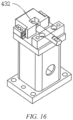
- the third positioning mechanism 43 comprises an inner holding member 431 and an outer holding member 432, the inner holding member 431 being configured to press the frame 1 from the inner periphery of the frame 1, and the outer holding member 432 being configured to press the frame 1 from the outer periphery of the frame 1.
- the inner holding member 431 is arranged on the inner side of the frame 1 located in the placement region, and the outer holding member 432 is arranged on the outer side of the frame 1 located in the placement region.
- a plurality of third positioning mechanisms 43 may be provided, and the plurality of third positioning mechanisms 43 are arranged at intervals around the placement region to position the frame 1.
- the inner holding member 431 moves towards the frame 1 and comes into contact with an inner wall of the frame 1, and the outer holding member 432 moves towards the frame 1 and comes into contact with the outer surface of the frame 1, the direction of movement of the inner holding member 431 being in the same line as the direction of movement of the outer holding member 432.
- the inner holding member 431 and the outer holding member 432 move towards the frame 1 so as to clamp the frame 1, so that the frame 1 is fixed in the placement region in position.
- the frame 1 When the through hole in the frame 1 fits with the positioning pin 411, the frame 1 is placed in the placement region, and the frame 1 is initially positioned by means of the first positioning mechanism 41.
- the pressing member 421 is turned over to press the frame 1 against the base 3, and the locking member 422 locks the pressing member 421, so as to fix the frame 1 to the base 3 to restrict the movement of the frame 1 in the first direction X.
- the inner holding member 431 and the outer holding member 432 move towards the frame 1 so as to clamp the frame 1, so as to fix the frame 1 on the base 3 in position to restrict the movement of the frame 1 in the second direction Y or in the third direction Z.
- the covering member 2 is a water cooling plate.
- the water cooling plate is a component for controlling the temperature of the battery cell inside the case, and the inner side of the water cooling plate is provided with a water channel through which water passes.
- the delivery of high-temperature water into the water channel of the water cooling plate can increase the temperature of the battery cell, so that the temperature of the battery cell can be maintained at an operating temperature.
- the delivery of low-temperature water into the water channel of the water cooling plate can reduce the temperature of the battery cell, so as to reduce the risk of thermal runaway of the battery cell to improve the safety of the battery cell.
- the present application further provides a welding device, comprising a welding fixture as described above and a welding execution unit which is configured to weld the covering member 2 to the frame 1.
- the present application provides a welding fixture configured to fix a frame 1 and a covering member 2, the covering member 2 covering a first opening of the frame 1, and the covering member 2 being a water cooling plate.
- the welding fixture comprises a base 3, a frame positioning mechanism 4, a negative pressure suction mechanism 5 and a heating mechanism 6.
- the base 3 comprises a placement region in which the frame 1 is placed, and the frame positioning mechanism 4 is arranged on the base 3 and configured to position the frame 1.
- the frame positioning mechanism 4 comprises a first positioning mechanism 41, a second positioning mechanism 42 and a third positioning mechanism 43.
- the first positioning mechanism 41 comprises a positioning pin 411 that can pass through a through hole in the frame 1 to restrict the movement of the frame 1.
- the second positioning mechanism 42 comprises a pressing member 421 for pressing the frame 1 against the base 3.
- the third positioning mechanism 43 comprises an inner holding member 431 for pressing the frame 1 from the inner side of the frame 1 and an outer holding member 432 for pressing the frame 1 from the outer side of the frame 1.
- the negative pressure suction mechanism 5 is arranged in the placement region.
- the negative pressure suction mechanism 5 comprises a plurality of first negative pressure suction units 51 and a plurality of second negative pressure suction units 52.
- the plurality of second negative pressure suction units 52 are arranged at intervals surrounding the center of the placement region, some of the plurality of first negative pressure suction units 51 are arranged surrounding the plurality of second negative pressure suction units 52, and the other of the plurality of first negative pressure suction units 51 are staggered with the plurality of second negative pressure suction units 52.
- the first negative pressure suction unit 51 is a bowl-shaped suction cup 511
- the second negative pressure suction unit 52 is a square suction cup 521.
- a heating mechanism 6 is arranged in the placement region and configured to heat the covering member 2.
- the heating mechanism 6 comprises heating plates 61.
- the heating plate 61 is made of silica gel, and the heating plate 61 is arranged in the placement region by means of a height-adjustable first holder 62.
- a plurality of heating plates 61 are provided, and the plurality of heating plates 61 are arranged surrounding the center of the placement region.
- the heating mechanism 6 further comprises a plurality of hot air blowers 64, and the bottom surface of the covering member 2 that is not attached to the heating plate 61 is heated by means of the plurality of hot air blowers 64.
- the present application further provides a welding device, comprising a welding fixture as described above and a welding execution unit.
- the welding execution unit is a stirring head for use in a FSW (Friction Stir Welding) process.
- the welding execution unit is rotationally inserted into the welding part between the frame 1 and the covering member 2, the friction between the welding execution unit and the frame 1 and the covering member 2 generates frictional heat to allow the frame 1 and the covering member 2 to undergo a thermoplasticizing process to achieve plastic flowing, and then solid-phase bonding is formed behind the welding execution unit under the upset-forging action of a stirring shaft shoulder.
- the covering member 2 is sucked by means of the negative pressure suction mechanism 5, so that the covering member 2 is fixed in position, and the suction force acts uniformly on the sucked surface of the covering member 2, thus reducing the risk of damage to the covering member 2 due to excessively concentrated stress.
- a plurality of first negative pressure suction units 51 pull the covering member 2 towards the frame 1 by the suction force, so that the covering member 2 is in close contact with the welding region of the frame 1, and then the second negative pressure suction unit 52 provides larger suction force for the covering member 2 to fix the covering member 2 in position, thus reducing the risk of displacement of the covering member 2 during welding.
- the covering member 2 is heated by means of the heating mechanism 6, the covering member 2 has volume expansion as it heats up, specifically, the edge of the covering member 2 extends in its own width and length directions, and then the frame 1 is welded to the volumetrically expanded covering member 2. After the welding is completed, the heating mechanism 6 stops heating, and as the temperature of the covering member 2 decreases, the covering member 2 tends to shrink. Since the edge of the covering member 2 has been welded to the frame 1, the shrinkage force of the covering member 2 acts on the central portion of the covering member 2 to stretch the central portion of the covering member 2 towards the edge of the covering member 2, so that the central portion of the covering member 2 is flattened ,thus improving the overall flatness of the covering member 2.
Landscapes
- Physics & Mathematics (AREA)
- Optics & Photonics (AREA)
- Engineering & Computer Science (AREA)
- Mechanical Engineering (AREA)
- Chemical & Material Sciences (AREA)
- Chemical Kinetics & Catalysis (AREA)
- Electrochemistry (AREA)
- General Chemical & Material Sciences (AREA)
- Lining Or Joining Of Plastics Or The Like (AREA)
Abstract
Description
- The present application claims the priority of
Chinese patent application no. 202211196034.3, entitled "WELDING FIXTURE AND WELDING DEVICE" and filed on September 29, 2022 - The present application relates to the technical field of battery production, and in particular to a welding fixture and a welding device.
- Achieving energy conservation and emission reduction is the key to the sustainable development of the automotive industry. Electric vehicles have become an important part of the sustainable development of the automotive industry due to their advantages in energy conservation and environmental protection. For the electric vehicles, the battery technology is an important factor to their development.
- A battery is composed of a case and a battery cell or a battery module accommodated in the case. The case typically comprises a frame and a covering member. When the case is to be assembled, the covering member is first welded to the frame. When the covering member is to be welded to the frame, as the covering member has an uneven structure on the surface, the uneven structure on the surface of the covering member is easy to be crushed by a pressing plate in a conventional fixing method where the covering member is pressed against the frame. For example, in the case where the covering member is a water cooling plate, as there are many bulging water channels on the water cooling plate, the water channels of the water cooling plate are easy to be crushed by the pressing plate, causing scrapping of the water cooling plate. This results in high production scrap rate and high production cost.
- In view of the above problems, an objective of the present application is to provide a welding fixture and a welding device, which can reduce the risk of damage to a covering member.
- In a first aspect, the present application provides a welding fixture configured to fix a frame and a covering member which covers a first opening of the frame, the welding fixture comprising a base, a frame positioning mechanism and a negative pressure suction mechanism, wherein the base comprises a placement region in which the frame is placed; the frame positioning mechanism is arranged on the base and configured to position the frame; and the negative pressure suction mechanism is arranged in the placement region and configured to generate negative pressure to suck the covering member so as to press the covering member against the frame.
- In the technical solution of the embodiments of the present application, after the frame is fixed to the placement region by means of the frame positioning mechanism, the negative pressure suction mechanism is located on an inner side of the fixed frame, the covering member is placed on the frame, a bottom surface of the covering member is sucked by means of the negative pressure suction mechanism, the covering member is closely attached to a welding region of the frame under the action of suction force, and the suction force of the negative pressure suction mechanism can uniformly act on a surface of the covering member, thus reducing the risk of damage to the covering member due to the excessively concentrated pressure.
- In some embodiments, the negative pressure suction mechanism comprises first negative pressure suction units and second negative pressure suction units, the number of the first negative pressure suction units being greater than that of the second negative pressure suction units, and the suction area of the first negative pressure suction unit being smaller than that of the second negative pressure suction unit.
- In the technical solution of the embodiments of the present application, after the covering member is placed on the frame that is fixed to the placement region, the first negative pressure suction units are arranged at intervals around the center of the covering member so that the suction force from the first negative pressure suction units can act on all parts of the covering member; and the plurality of first negative pressure suction units apply smaller suction force to the covering member to allow the covering member to be in close contact with the welding region of the frame, and the second negative pressure suction units then apply larger suction force to the covering member to fix the covering member in position, thus reducing the risk of displacement of the covering member during welding.
- In some embodiments, the plurality of first negative pressure suction units are arranged at intervals around the second negative pressure suction units.
- In the technical solution of the embodiments of the present application, the first negative pressure suction units are closer to the covering member and the welding region of the frame than the second negative pressure suction units, and the portion of the covering member near the edge can be sucked by means of the plurality of first negative pressure suction units and pulled towards the welding region of the frame, so that the covering member is closely attached to the welding region of the frame, while the surface of the covering member that is in contact with the frame is also stressed uniformly, thus reducing the risk of partial tilt of the covering member.
- In some embodiments, the first negative pressure suction unit is a bowl-shaped suction cup, and the second negative pressure suction unit is a square suction cup.
- In the technical solution of the embodiments of the present application, when sucking the covering member, the bowl-shaped suction cup expels the air in the interior to reduce its own volume, so that the covering member is pulled towards the welding region of the frame to allow the covering member to be closely attached to the welding region of the frame, thus reducing the risk of partial tilt of the covering member. The square suction cup has a larger contact surface with the covering member and can provide larger suction force for the covering member, thus reducing the risk of displacement of the covering member during welding.
- In some embodiments, the welding fixture further comprises a heating mechanism arranged in the placement region and configured to heat the covering member.
- In the technical solution of the embodiments of the present application, after the covering member is placed on the frame, the covering member is heated by means of the heating mechanism, the covering member has volume expansion as it heats up, specifically, the edge of the covering member extends in its own width and length directions, and then the frame is welded to the volumetrically expanded covering member. After the welding is completed, the heating mechanism stops heating, and as the temperature of the covering member decreases, the covering member tends to shrink. Since the edge of the covering member has been welded to the frame, the shrinking force of the covering member acts on the central portion of the covering member to stretch the central portion of the covering member towards the edge of the covering member, so that the central portion of the covering member is flattened, thus improving the overall flatness of the covering member.
- In some embodiments, the heating mechanism comprises a heating plate, which comprises an elastic insulation layer and an electric heating wire embedded in the elastic insulation layer and is configured to be attached to the covering member for heating the covering member.
- In the technical solution of the embodiments of the present application, the elastic insulation layer is closely attached to the covering member in the form of surface contact, and the covering member is heated by the electric heating wire via the elastic insulation layer, so that the covering member can be heated uniformly.
- In some embodiments, the elastic insulation layer is made of silica gel.
- In the technical solution of the embodiments of the present application, on the one hand, silica gel is soft and not easy to scratch the covering member, and on the other hand, silica gel can deform depending on the shape of the surface of the covering member to allow itself to be completely attached to the covering member, so that the covering member can be heated uniformly.
- In some embodiments, the heating mechanism comprises the plurality of heating plates arranged in the same plane and spaced apart from each other.
- In the technical solution of the embodiments of the present application, when the negative pressure suction mechanism comprises the second negative pressure suction unit and the plurality of first negative pressure suction units, the plurality of heating plates are staggered with the second negative pressure suction unit and the plurality of first negative pressure suction units, so that the covering member can be heated uniformly while receiving the suction force uniformly at all parts.
- In some embodiments, the heating mechanism further comprises a height-adjustable first holder arranged in the placement region and configured to support the heating plate.
- In the technical solution of the embodiments of the present application, the first holder can adjust its height adapted to the frame that is fixed to the placement region, so that a top surface of the heating plate can be attached to the bottom surface of the covering member, which is convenient for the heating plate to heat the covering member.
- In some embodiments, the heating mechanism further comprises a hot air blower configured to blow hot air to the covering member.
- In the technical solution of the embodiments of the present application, the hot air blower can blow hot air to the surface of the covering member that is not attached to the heating plate, so that the covering member is heated and can be heated uniformly.
- In some embodiments, the frame positioning mechanism comprises a first positioning mechanism comprising a positioning pin which extends in a thickness direction of the covering member and fits with a through hole in the frame to achieve positioning for the frame.
- In the technical solution of the embodiments of the present application, in the process of placing the frame in the placement region, the through hole in the frame fits with the positioning pin to restrict the movement of the frame in a second direction or in a third direction so as to provide initial positioning for the frame, and then the frame comes into contact with the placement region of the base.
- In some embodiments, the frame positioning mechanism comprises a second positioning mechanism comprising a pressing member and a locking member, the pressing member being rotatably connected to the base and configured to switch between a pressing position and a release position, and the locking member being configured to lock the pressing member in the pressing position to allow the pressing member to press the frame against the base.
- In the technical solution of the embodiments of the present application, the pressing member is turned over to press the frame against the base to restrict the movement of the frame in the first direction and further provide positioning for the frame placed in the placement region.
- In some embodiments, the frame positioning mechanism comprises a third positioning mechanism comprising an inner holding member and an outer holding member, the inner holding member being configured to press the frame from the inner periphery of the frame, and the outer holding member being configured to press the frame from the outer periphery of the frame.
- In the technical solution of the embodiments of the present application, the inner holding member and the outer holding member move towards the frame so as to clamp the frame, so that the frame is fixed in the placement region in position.
- In some embodiments, the covering member is a water cooling plate.
- In a second aspect, the present application provides a welding device, comprising a welding fixture according to the first aspect and a welding execution unit which is configured to weld the covering member to the frame.
- Some of the additional aspects and advantages of the present application will be set forth in the following description, and some will become apparent from the following description, or be learned by practice of the present application.
- In order to more clearly describe the technical solutions of embodiments of the present application, the accompanying drawings required in the embodiments will be described briefly below. It should be understood that the following accompanying drawings illustrate only some embodiments of the present application and therefore should not be construed as a limitation on the scope thereof. For those of ordinary skill in the art, other relevant accompanying drawings can also be obtained from these accompanying drawings without any creative effort.
-
FIG. 1 is an exploded view of a welding fixture according to some embodiments of the present application; -
FIG. 2 is a schematic structural diagram of a welding fixture according to some embodiments of the present application; -
FIG. 3 is a top view of a welding fixture according to some embodiments of the present application; -
FIG. 4 is a cross-sectional view taken along line A-A inFIG. 3 when no covering member is provided; -
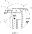
FIG. 5 is an enlarged view of part B inFIG. 4 when a covering member is placed; -
FIG. 6 is a schematic structural diagram of a first negative pressure suction unit according to some embodiments of the present application; -
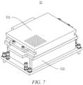
FIG. 7 is a schematic structural diagram of a second negative pressure suction unit according to some embodiments of the present application; -
FIG. 8 is an exploded view of a second negative pressure suction unit according to some embodiments of the present application; -
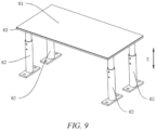
FIG. 9 is a schematic structural diagram of a heating mechanism according to some embodiments of the present application; -
FIG. 10 is an exploded view of a heating mechanism according to some embodiments of the present application; -
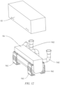
FIG. 11 is a schematic structural diagram of a hot air blower and a protective cover according to some embodiments of the present application; -
FIG. 12 is an exploded view of a hot air blower and a protective cover according to some embodiments of the present application; -
FIG. 13 is a schematic structural diagram of a first positioning mechanism according to some embodiments of the present application; -
FIG. 14 is a schematic structural diagram of a second positioning mechanism according to some embodiments of the present application; -
FIG. 15 is a schematic structural diagram of an inner holding member of a third positioning mechanism according to some embodiments of the present application; and -
FIG. 16 is a schematic structural diagram of an outer holding member of the third positioning mechanism according to some embodiments of the present application. - List of reference signs: 1 - frame; 10 - connecting portion; 2 - covering member; 3 - base; 4 - frame positioning mechanism; 41 - first positioning mechanism; 411- positioning pin; 412 - first mounting base; 42 - second positioning mechanism; 421 - pressing member; 422 - locking member; 43 - third positioning mechanism; 431 - inner holding member; 432 - outer holding member; 5 - negative pressure suction mechanism; 51 - first negative pressure suction unit; 52 - second negative pressure suction unit; 511 - bowl-shaped suction cup; 512 - first mounting leg; 521 - square suction cup; 522 - second mounting base; 6 - heating mechanism; 61 - heating plate; 62 - first holder; 63 - supporting member; 64 - hot air blower; 641 - second holder; 642 - air duct; 65 - protective cover; X - first direction; Y - second direction; Z - third direction.
- In order to make the objectives, technical solutions and advantages of embodiments of the present application clearer, the technical solutions in the embodiments of the present application will be described clearly and completely below with reference to the accompanying drawings in the embodiments of the present application. Apparently, the embodiments described are some of, rather than all of, the embodiments of the present application. Based on the embodiments of the present application, all other embodiments obtained by those of ordinary skill in the art without any creative effort fall within the scope of protection of the present application.
- Unless otherwise defined, all technical and scientific terms used in the present application have the same meanings as those commonly understood by those skilled in the art to which the present application belongs. The terms used in the description of the present application are merely for the purpose of describing specific embodiments, but are not intended to limit the present application. The terms "comprising" and "having" and any variations thereof in the description and the claims of the present application as well as the brief description of the accompanying drawings described above are intended to cover non-exclusive inclusion. The terms "first", "second", etc. in the description and the claims of the present application as well as the foregoing accompanying drawings are used to distinguish between different objects, rather than describing a specific order or a primary-secondary relationship.
- In the present application, the phrase "embodiment" mentioned means that the specific features, structures and characteristics described in conjunction with the embodiments may be included in at least one embodiment of the present application. The phrase at various locations in the description does not necessarily refer to the same embodiment, or an independent or alternative embodiment exclusive of another embodiment. Those skilled in the art should understand, in explicit and implicit manners, that an embodiment described in the present application can be combined with another embodiment.
- In the description of the present application, it should be noted that, the terms "mount", "connected", "connect", or "attach" should be interpreted in a broad sense unless explicitly defined and limited otherwise. For example, they may be a fixed connection, a detachable connection, or an integral connection; or may be a direct connection, an indirect connection by means of an intermediate medium, or internal communication between two elements. For those of ordinary skill in the art, the specific meanings of the foregoing terms in the present application may be understood according to specific circumstances.
- The term "and/or" in the present application is merely a description of the associated relationship of associated objects, representing that three relationships may exist, for example, A and/or B, may be expressed as: only A exists, both A and B exist, and only B exists. In addition, the character "/" in the present application generally indicates that the associated objects before and after the character are in a relationship of "or".
- In the present application, "a plurality of" means two or more (including two), similarly, "a plurality of groups" means two or more groups (including two groups), and "a plurality of pieces" means two or more pieces (including two pieces).
- At present, from the perspective of the development of the market situation, traction batteries are used increasingly widely. The traction batteries are not only used in energy storage power systems such as hydroelectric power plants, thermal power plants, wind power plants and solar power plants, but also widely used in electric transportation means such as electric bicycles, electric motorcycles, and electric vehicles and in many fields such as military equipment and aerospace. With the continuous expansion of the application field of traction batteries, the market demand for the traction batteries is also expanding.
- A battery mentioned in the present application refers to a single physical module comprising one or more battery cells to provide a higher voltage and capacity. The battery generally comprises a case for packaging one or more battery cells. The case can prevent liquid or other foreign matter from affecting charging or discharging of the battery cell(s).
- The case comprises a frame and a covering member, such as a water cooling plate, welded to the frame.
- During the process of welding the covering member and the frame, in a conventional method for fixing the covering member, the covering member is pressed against a welding region of the frame by means of a pressing plate, and the covering member having an uneven structure on the surface may be deformed or even damaged when being pressed by the pressing plate. For example, in the case where the covering member is a water cooling plate, when the pressing plate is pressed against the water cooling plate, the pressing plate is pressed against a bulging water channel of the water cooling plate, and with the small contact surface between the pressing plate and the water channel of the water cooling plate, the water channel of the water cooling plate is easy to be damaged by pressing, causing scrapping of the water cooling plate, resulting in high production scrap rate and high production cost.
- Based on the above considerations, in order to solve the problem in the prior art that the fixing for the covering member may cause damage to the covering member, the present application designs a welding fixture. A negative pressure suction mechanism is provided in a placement region on a base where the frame is placed. The negative pressure suction mechanism can generate negative pressure to suck the covering member towards the frame to allow the covering member to be closely attached to the frame, and the suction force generated by the negative pressure mechanism can uniformly act on the sucked surface of the covering member, thus reducing the risk of damage to the covering member, increasing the production yield, and reducing the production cost.
- The welding fixture disclosed in the embodiments of the present application may be applicable to, but not limited to, a welding process for a case of a battery, and may also be applicable to a welding process for a case of other devices.
- According to some embodiments of the present application, as shown in
FIGS. 1 to 5 , the present application provides a welding fixture configured to fix aframe 1 and a coveringmember 2, the coveringmember 2 covering a first opening of theframe 1, the welding fixture comprising abase 3, aframe positioning mechanism 4 and a negativepressure suction mechanism 5. Thebase 3 comprises a placement region in which theframe 1 is placed. Theframe positioning mechanism 4 is arranged on thebase 3 and configured to position theframe 1. The negativepressure suction mechanism 5 is arranged in the placement region and configured to generate negative pressure to suck the coveringmember 2 so as to press the coveringmember 2 against theframe 1. - The placement region may be a central region of a top surface of the
base 3. - The covering
member 2 may be a water cooling plate. Alternatively, the coveringmember 2 may be a base plate of the case. Alternatively, the surface of the coveringmember 2 may be provided with a groove adapted to a battery cell. - A plurality of negative
pressure suction mechanisms 5 may be provided. The plurality of negativepressure suction mechanisms 5 may be arranged at intervals in the placement region, and the plurality of negativepressure suction mechanisms 5 may be arranged in a way of avoiding uneven parts of the surface of the coveringmember 2. - After the
frame 1 is fixed in the placement region by means of theframe positioning mechanism 4, the negativepressure suction mechanism 5 is located on an inner side of the fixedframe 1, the coveringmember 2 is placed on theframe 1, a bottom surface of the coveringmember 2 is sucked by means of the negativepressure suction mechanism 5, the coveringmember 2 is closely attached to a welding region of theframe 1 under the action of suction force, and the suction force of the negativepressure suction mechanism 5 can uniformly act on a surface of the coveringmember 2, thus reducing the risk of damage to the coveringmember 2 due to the excessively concentrated pressure. - According to some embodiments of the present application, optionally, as shown in
FIGS. 1 ,2 and4 , the negativepressure suction mechanism 5 comprises first negativepressure suction units 51 and second negativepressure suction units 52, the number of the first negativepressure suction units 51 being greater than that of the second negativepressure suction units 52, and the suction area of the first negativepressure suction unit 51 being smaller than that of the second negativepressure suction unit 52. - The plurality of first negative
pressure suction units 51 may be arranged around the second negativepressure suction units 52. - One second negative
pressure suction unit 52 may be provided. Alternatively, a plurality of (e.g., two, three, four, or five) second negativepressure suction units 52 may be provided. - For example, in the case where the covering
member 2 is a water cooling plate, the plurality of first negativepressure suction units 51 can be arranged in a way of avoiding the water channel of the water cooling plate. - After the covering
member 2 is placed on theframe 1 that is fixed to the placement region, the first negativepressure suction units 51 are arranged at intervals around the center of the coveringmember 2 so that suction force from the first negativepressure suction units 51 can act on all parts of the coveringmember 2; and the plurality of first negativepressure suction units 51 apply smaller suction force to the coveringmember 2 to allow the coveringmember 2 to be in close contact with the welding region of theframe 1, and the second negativepressure suction units 52 then apply larger suction force to the coveringmember 2 to fix the coveringmember 2 in position, thus reducing the risk of displacement of the coveringmember 2 during welding. - According to some embodiments of the present application, optionally, as shown in
FIGS. 1 ,2 and4 , the plurality of first negativepressure suction units 51 are arranged at intervals around the second negativepressure suction units 52. - One second negative
pressure suction unit 52 may be provided, and the second negativepressure suction unit 52 is arranged at a position directly facing the center of the coveringmember 2. Alternatively, a plurality of (e.g., two, three, four, or five) second negativepressure suction units 52 may be provided, and the plurality of second negativepressure suction units 52 are arranged at intervals surrounding the center of the coveringmember 2. - The first negative
pressure suction units 51 are closer to the coveringmember 2 and the welding region of theframe 1 than the second negativepressure suction unit 52, and the portion of the coveringmember 2 near the edge can be sucked by means of the plurality of first negativepressure suction units 51 and pulled towards the welding region of theframe 1, so that the coveringmember 2 is closely attached to the welding region of theframe 1, while the surface of the coveringmember 2 that is in contact with theframe 1 is stressed uniformly, thus reducing the risk of partial tilt of the coveringmember 2. - According to some embodiments of the present application, optionally, as shown in
FIGS. 4 and6 to 8 , the first negativepressure suction unit 51 is a bowl-shapedsuction cup 511, and the second negativepressure suction unit 52 is asquare suction cup 521. - A suction cup is a component that expels the air or liquid in the interior so as to fix itself to a non-porous surface under atmospheric pressure or liquid pressure.
- The bowl-shaped
suction cup 511 may be made of an elastic material, and after coming into contact with the coveringmember 2, the bowl-shapedsuction cup 511 may be deformed depending on the shape of the bottom surface of the coveringmember 2 to allow itself to be attached to the bottom surface of the coveringmember 2, thus reducing the risk of leakage of the suction force to enable the bowl-shapedsuction cup 511 to stably suck the coveringmember 2. - The bowl-shaped
suction cup 511 can be mounted in the placement region by means of a first mountingleg 512. The mounting leg may be provided with a plurality of bowl-shapedsuction cups 511. - The
square suction cup 521 may be made of an elastic material, and after coming into contact with the coveringmember 2, thesquare suction cup 521 may be deformed depending on the shape of the bottom surface of the coveringmember 2 to allow itself to be attached to the bottom surface of the coveringmember 2, thus reducing the risk of leakage of the suction force to enable thesquare suction cup 521 to stably suck the coveringmember 2. - The
square suction cup 521 can be mounted in the placement region by means of asecond mounting base 522. - When the
frame 1 is fixed to the placement region of thebase 3, a top surface of the bowl-shapedsuction cup 511 may exceed a top surface of theframe 1. In the process of placing the coveringmember 2 in theframe 1, the coveringmember 2 comes into contact with the top surface of the bowl-shapedsuction cup 511, and then the air in the interior of the bowl-shapedsuction cup 511 is drawn out by means of a vacuum cylinder to form local vacuum to suck the coveringmember 2. After the air in the interior is drawn out, the bowl-shapedsuction cup 511 shrinks to pull the coveringmember 2 towards theframe 1, so that theframe 1 is attached to the welding region of theframe 1, while the bottom surface of the coveringmember 2 comes into contact with thesquare suction cup 521, which is convenient for thesquare suction cup 521 to suck the coveringmember 2 to fix the coveringmember 2 in position. - When sucking the covering
member 2, the bowl-shapedsuction cup 511 expels the air in the interior to reduce its own volume, and then the coveringmember 2 is pulled towards the welding region of theframe 1 to allow the coveringmember 2 to be closely attached to the welding region of theframe 1, thus reducing the risk of partial tilt of the coveringmember 2. Thesquare suction cup 521 has a larger contact surface with the coveringmember 2 and can provide larger suction force for the coveringmember 2, thus reducing the risk of displacement of the coveringmember 2 during welding. - According to some embodiments of the present application, optionally, as shown in
FIGS. 1 and2 , the welding fixture further comprises aheating mechanism 6. Theheating mechanism 6 is arranged in the placement region and configured to heat the coveringmember 2. - The
heating mechanism 6 is located on the inner side of theframe 1 that is fixed in the placement region, and the bottom surface of the coveringmember 2 faces theheating mechanism 6. - The
heating mechanism 6 may comprise aheating plate 61 attached to the bottom surface of the coveringmember 2 and heating the coveringmember 2 uniformly. Alternatively, theheating mechanism 6 may comprise a heating lamp arranged at a distance from the bottom surface of the coveringmember 2 and heating the coveringmember 2 by thermal radiation. - A second direction Y as shown is a length direction of the covering
member 2. A third direction Z as shown is a width direction of the covering member. - After the covering
member 2 is placed on theframe 1, the coveringmember 2 is heated by means of theheating mechanism 6, the coveringmember 2 has volume expansion as it heats up, specifically, the edge of the coveringmember 2 extends in its own width and length directions, and then theframe 1 is welded to the volumetrically expanded coveringmember 2. After the welding is completed, theheating mechanism 6 stops heating, and as the temperature of the coveringmember 2 decreases, the coveringmember 2 tends to shrink. Since the edge of the coveringmember 2 has been welded to theframe 1, the shrinkage force of the coveringmember 2 acts on the central portion of the coveringmember 2 to stretch the central portion of the coveringmember 2 towards the edge of the coveringmember 2, so that the central portion of the coveringmember 2 is flattened, thus improving the overall flatness of the coveringmember 2. - According to some embodiments of the present application, optionally, as shown in
FIGS. 9 and10 , theheating mechanism 6 comprises aheating plate 61. Theheating plate 61 comprises an elastic insulation layer and an electric heating wire embedded in the elastic insulation layer, and theheating plate 61 is configured to be attached to the coveringmember 2 for heating the coveringmember 2. - The material of the elastic insulation layer may be, but not limited to, engineering plastic, resin, rubber, silica gel, etc.
- The elastic insulation layer is closely attached to the covering
member 2 in the form of surface contact, and the coveringmember 2 is heated by the electric heating wire via the elastic insulation layer, so that the coveringmember 2 can be heated uniformly. - According to some embodiments of the present application, optionally, the elastic insulation layer is made of silica gel.
- Silica gel is hydrated silica in a granular porous form, has temperature resistance and electrical insulation properties, can be used in high-temperature environments, and has a surface that is soft and easy to deform and is also smooth and not easy to stick.
- On the one hand, silica gel is soft and not easy to scratch the covering
member 2, and on the other hand, silica gel can deform depending on the shape of the surface of the coveringmember 2 to allow itself to be completely attached to the coveringmember 2, so that the coveringmember 2 can be heated uniformly. - According to some embodiments of the present application, optionally, as shown in
FIGS. 1 and2 , theheating mechanism 6 comprises a plurality ofheating plates 61 arranged in the same plane and spaced apart from each other. - Two, three, four, five, six, seven, or
more heating plates 61 may be provided. - The plurality of
heating plates 61 may be arranged surrounding the negativepressure suction mechanism 5. Alternatively, the plurality ofheating plates 61 may be staggered with the plurality of first negativepressure suction units 51 and the second negativepressure suction units 52. - When the negative
pressure suction mechanism 5 comprises the second negativepressure suction unit 52 and the plurality of first negativepressure suction units 51, the plurality ofheating plates 61 are staggered with the second negativepressure suction unit 52 and the plurality of first negativepressure suction units 51, so that the coveringmember 2 can be heated uniformly while receiving the suction force uniformly at all parts. - According to some embodiments of the present application, optionally, as shown in
FIGS. 9 and10 , theheating mechanism 6 further comprises a height-adjustablefirst holder 62. Thefirst holder 62 is arranged in the placement region, and thefirst holder 62 is configured to support theheating plate 61. - The
heating mechanism 6 may further comprise a supportingmember 63. The supportingmember 63 is supported between theheating plate 61 and thefirst holder 62. The supportingmember 63 has a flat top surface that is attached to a bottom surface of theheating plate 61, so that theheating plate 61 can be kept flat and attached to the coveringmember 2. - One
first holder 62 may be provided, and thefirst holder 62 is supported at the center of theheating plate 61. Alternatively, a plurality offirst holders 62 may be provided, and the plurality offirst holders 62 are arranged at intervals surrounding the center of theheating plate 61. - The
first holder 62 can adjust its height adapted to theframe 1 that is fixed to the placement region, so that a top surface of theheating plate 61 can be attached to the bottom surface of the coveringmember 2, which is convenient for theheating plate 61 to heat the coveringmember 2. - According to some embodiments of the present application, optionally, as shown in
FIGS. 1 ,2 ,11 and12 , theheating mechanism 6 further comprises ahot air blower 64. Thehot air blower 64 is configured to blow hot air to the coveringmember 2. - The
hot air blower 64 may be mounted in the placement region by means of a plurality ofsecond holders 641. - An output end of the
hot air blower 64 may be connected to anair duct 642. Theair duct 642 is configured to direct hot air towards the bottom surface of the coveringmember 2 for heating the coveringmember 2. - The
heating mechanism 6 further comprises aprotective cover 65. Theprotective cover 65 covers the outer side of thehot air blower 64 to protect thehot air blower 64. - A plurality of (e.g., two, three, four or five)
hot air blowers 64 may be provided, and the plurality ofhot air blowers 64 are arranged at intervals around the center of the placement region. - The
hot air blowers 64 can blow hot air for heating the surface of the coveringmember 2 that is not attached to theheating plate 61, so that the coveringmember 2 can be heated uniformly. - In some embodiments, the welding fixture further comprises weld seam supporting blocks arranged in the placement region and around the
heating mechanism 6 and configured to support the welding part between the coveringmember 2 and theframe 1. The weld seam supporting block is provided with a heat insulation layer on the side near theheating mechanism 6, and the heat insulation layer may be made of, but not limited to, heat insulation wool, polystyrene foam board, etc. The heat insulation layer can inhibit the process of heat transferred to theframe 1 and then dissipated via theframe 1, shorten the heating time of the coveringmember 2, reduce the energy loss of theheating mechanism 6 during heating the coveringmember 2, and allow the heat to be enclosed on the inner side of theframe 1 and concentrated on the coveringmember 2 so as to increase the heating rate of the coveringmember 2. - According to some embodiments of the present application, optionally, as shown in
FIGS. 1 ,2 and13 , theframe positioning mechanism 4 comprises afirst positioning mechanism 41. Thefirst positioning mechanism 41 comprises apositioning pin 411, thepositioning pin 411 extends in a thickness direction of the coveringmember 2, thefirst positioning mechanism 41 is arranged in thebase 3 by means of afirst mounting base 412, and thepositioning pin 411 fits with a through hole in theframe 1 to achieve positioning for theframe 1. - The first direction X as shown is the thickness direction of the covering
member 2. - The first positioning mechanism further comprises the
first mounting base 412, an outer wall of theframe 1 is provided with a connectingportion 10 for connecting other components, the connectingportion 10 is provided with a through hole through which a fastener (e.g., a screw or a bolt) passes, and thepositioning pin 411 may pass through or be pulled out of the through hole in the connectingportion 10. - A plurality of
first positioning mechanisms 41 may be provided, and the plurality offirst positioning mechanisms 41 are arranged at intervals around the placement region. - In the process of placing the
frame 1 in the placement region, the through hole in theframe 1 fits with thepositioning pin 411 to restrict the movement of theframe 1 in the second direction Y or in the third direction Z so as to provide initial positioning for theframe 1, and then theframe 1 comes into contact with the placement region of thebase 3. - According to some embodiments of the present application, optionally, as shown in
FIGS. 1 ,2 and14 , theframe positioning mechanism 4 comprises asecond positioning mechanism 42. Thesecond positioning mechanism 42 comprises apressing member 421 and a lockingmember 422, the pressingmember 421 being rotatably connected to thebase 3, the pressingmember 421 being configured to switch between a pressing position and a release position, and the lockingmember 422 being configured to lock thepressing member 421 in the pressing position to allow thepressing member 421 to press theframe 1 against thebase 3. - The pressing
member 421 may be a pressing arm, one end of which is rotatably connected to thebase 3. After theframe 1 is placed in the placement region, the pressing arm is turned over so that the other end of the pressing arm is pressed against the top surface of theframe 1. The lockingmember 422 may be a positioning bolt, and thebase 3 is provided with a threaded hole adapted to the positioning bolt. When the pressing arm is in the pressing position, the positioning bolt is in threaded fit with the threaded hole to lock the pressing arm in the state of pressing theframe 1. After the welding is completed, the positioning bolt is disengaged from the bolt hole, the pressing arm is turned away from theframe 1, and the pressing arm is switched from the pressing position to the release position. - A plurality of
second positioning mechanisms 42 may be provided, and the plurality ofsecond positioning mechanisms 42 are arranged at intervals around the placement region to press theframe 1 against thebase 3. - The pressing
member 421 is turned over to press theframe 1 against thebase 3 to restrict the movement of theframe 1 in the first direction X and further provide positioning for theframe 1 placed in the placement region. - According to some embodiments of the present application, optionally, as shown in
FIGS. 2 ,15 and16 , theframe positioning mechanism 4 comprises athird positioning mechanism 43. Thethird positioning mechanism 43 comprises aninner holding member 431 and an outer holdingmember 432, theinner holding member 431 being configured to press theframe 1 from the inner periphery of theframe 1, and the outer holdingmember 432 being configured to press theframe 1 from the outer periphery of theframe 1. - The
inner holding member 431 is arranged on the inner side of theframe 1 located in the placement region, and the outer holdingmember 432 is arranged on the outer side of theframe 1 located in the placement region. - A plurality of
third positioning mechanisms 43 may be provided, and the plurality ofthird positioning mechanisms 43 are arranged at intervals around the placement region to position theframe 1. - The
inner holding member 431 moves towards theframe 1 and comes into contact with an inner wall of theframe 1, and the outer holdingmember 432 moves towards theframe 1 and comes into contact with the outer surface of theframe 1, the direction of movement of theinner holding member 431 being in the same line as the direction of movement of the outer holdingmember 432. - The
inner holding member 431 and the outer holdingmember 432 move towards theframe 1 so as to clamp theframe 1, so that theframe 1 is fixed in the placement region in position. - When the through hole in the
frame 1 fits with thepositioning pin 411, theframe 1 is placed in the placement region, and theframe 1 is initially positioned by means of thefirst positioning mechanism 41. The pressingmember 421 is turned over to press theframe 1 against thebase 3, and the lockingmember 422 locks thepressing member 421, so as to fix theframe 1 to thebase 3 to restrict the movement of theframe 1 in the first direction X. Theinner holding member 431 and the outer holdingmember 432 move towards theframe 1 so as to clamp theframe 1, so as to fix theframe 1 on thebase 3 in position to restrict the movement of theframe 1 in the second direction Y or in the third direction Z. - According to some embodiments of the present application, optionally, the covering
member 2 is a water cooling plate. - The water cooling plate is a component for controlling the temperature of the battery cell inside the case, and the inner side of the water cooling plate is provided with a water channel through which water passes.
- When the battery is in a low temperature environment, the delivery of high-temperature water into the water channel of the water cooling plate can increase the temperature of the battery cell, so that the temperature of the battery cell can be maintained at an operating temperature. When the battery is in a high temperature environment, the delivery of low-temperature water into the water channel of the water cooling plate can reduce the temperature of the battery cell, so as to reduce the risk of thermal runaway of the battery cell to improve the safety of the battery cell.
- According to some embodiments of the present application, optionally, the present application further provides a welding device, comprising a welding fixture as described above and a welding execution unit which is configured to weld the covering
member 2 to theframe 1. - According to some embodiments of the present application, optionally, as shown in
FIGS. 1 to 16 , the present application provides a welding fixture configured to fix aframe 1 and a coveringmember 2, the coveringmember 2 covering a first opening of theframe 1, and the coveringmember 2 being a water cooling plate. The welding fixture comprises abase 3, aframe positioning mechanism 4, a negativepressure suction mechanism 5 and aheating mechanism 6. Thebase 3 comprises a placement region in which theframe 1 is placed, and theframe positioning mechanism 4 is arranged on thebase 3 and configured to position theframe 1. Theframe positioning mechanism 4 comprises afirst positioning mechanism 41, asecond positioning mechanism 42 and athird positioning mechanism 43. Thefirst positioning mechanism 41 comprises apositioning pin 411 that can pass through a through hole in theframe 1 to restrict the movement of theframe 1. Thesecond positioning mechanism 42 comprises apressing member 421 for pressing theframe 1 against thebase 3. Thethird positioning mechanism 43 comprises aninner holding member 431 for pressing theframe 1 from the inner side of theframe 1 and an outer holdingmember 432 for pressing theframe 1 from the outer side of theframe 1. The negativepressure suction mechanism 5 is arranged in the placement region. The negativepressure suction mechanism 5 comprises a plurality of first negativepressure suction units 51 and a plurality of second negativepressure suction units 52. The plurality of second negativepressure suction units 52 are arranged at intervals surrounding the center of the placement region, some of the plurality of first negativepressure suction units 51 are arranged surrounding the plurality of second negativepressure suction units 52, and the other of the plurality of first negativepressure suction units 51 are staggered with the plurality of second negativepressure suction units 52. The first negativepressure suction unit 51 is a bowl-shapedsuction cup 511, and the second negativepressure suction unit 52 is asquare suction cup 521. Aheating mechanism 6 is arranged in the placement region and configured to heat the coveringmember 2. Theheating mechanism 6 comprisesheating plates 61. Theheating plate 61 is made of silica gel, and theheating plate 61 is arranged in the placement region by means of a height-adjustablefirst holder 62. A plurality ofheating plates 61 are provided, and the plurality ofheating plates 61 are arranged surrounding the center of the placement region. Theheating mechanism 6 further comprises a plurality ofhot air blowers 64, and the bottom surface of the coveringmember 2 that is not attached to theheating plate 61 is heated by means of the plurality ofhot air blowers 64. - The present application further provides a welding device, comprising a welding fixture as described above and a welding execution unit. The welding execution unit is a stirring head for use in a FSW (Friction Stir Welding) process. The welding execution unit is rotationally inserted into the welding part between the
frame 1 and the coveringmember 2, the friction between the welding execution unit and theframe 1 and the coveringmember 2 generates frictional heat to allow theframe 1 and the coveringmember 2 to undergo a thermoplasticizing process to achieve plastic flowing, and then solid-phase bonding is formed behind the welding execution unit under the upset-forging action of a stirring shaft shoulder. - The covering
member 2 is sucked by means of the negativepressure suction mechanism 5, so that the coveringmember 2 is fixed in position, and the suction force acts uniformly on the sucked surface of the coveringmember 2, thus reducing the risk of damage to the coveringmember 2 due to excessively concentrated stress. A plurality of first negativepressure suction units 51 pull the coveringmember 2 towards theframe 1 by the suction force, so that the coveringmember 2 is in close contact with the welding region of theframe 1, and then the second negativepressure suction unit 52 provides larger suction force for the coveringmember 2 to fix the coveringmember 2 in position, thus reducing the risk of displacement of the coveringmember 2 during welding. The coveringmember 2 is heated by means of theheating mechanism 6, the coveringmember 2 has volume expansion as it heats up, specifically, the edge of the coveringmember 2 extends in its own width and length directions, and then theframe 1 is welded to the volumetrically expanded coveringmember 2. After the welding is completed, theheating mechanism 6 stops heating, and as the temperature of the coveringmember 2 decreases, the coveringmember 2 tends to shrink. Since the edge of the coveringmember 2 has been welded to theframe 1, the shrinkage force of the coveringmember 2 acts on the central portion of the coveringmember 2 to stretch the central portion of the coveringmember 2 towards the edge of the coveringmember 2, so that the central portion of the coveringmember 2 is flattened ,thus improving the overall flatness of the coveringmember 2. - Although the present application has been described with reference to the preferred embodiments, various modifications can be made, and equivalents can be provided to substitute for the components thereof without departing from the scope of the present application. In particular, the technical features mentioned in the embodiments can be combined in any manner, provided that there is no structural conflict. The present application is not limited to the specific embodiments disclosed herein but includes all the technical solutions that fall within the scope of the claims.
Claims (15)
- A welding fixture configured to fix a frame and a covering member which covers a first opening of the frame, the welding fixture comprising:a base comprising a placement region in which the frame is placed;a frame positioning mechanism arranged on the base and configured to position the frame; anda negative pressure suction mechanism arranged in the placement region and configured to generate negative pressure to suck the covering member so as to press the covering member against the frame.
- The welding fixture according to claim 1, wherein the negative pressure suction mechanism comprises first negative pressure suction units and second negative pressure suction units, the number of the first negative pressure suction units being greater than that of the second negative pressure suction units, and the suction area of the first negative pressure suction unit being smaller than that of the second negative pressure suction unit.
- The welding fixture according to claim 2, wherein the plurality of first negative pressure suction units are arranged at intervals around the second negative pressure suction units.
- The welding fixture according to claim 2 or 3, wherein the first negative pressure suction unit is a bowl-shaped suction cup, and the second negative pressure suction unit is a square suction cup.
- The welding fixture according to any one of claims 1-4, further comprising:
a heating mechanism arranged in the placement region and configured to heat the covering member. - The welding fixture according to claim 5, wherein the heating mechanism comprises a heating plate, which comprises an elastic insulation layer and an electric heating wire embedded in the elastic insulation layer and is configured to be attached to the covering member for heating the covering member.
- The welding fixture according to claim 6, wherein the elastic insulation layer is made of silica gel.
- The welding fixture according to claim 6 or 7, wherein the heating mechanism comprises the plurality of heating plates arranged in the same plane and spaced apart from each other.
- The welding fixture according to any one of claims 6-8, wherein the heating mechanism further comprises a height-adjustable first holder arranged in the placement region and configured to support the heating plate.
- The welding fixture according to any one of claims 5-9, wherein the heating mechanism further comprises a hot air blower configured to blow hot air to the covering member.
- The welding fixture according to any one of claims 1-10, wherein the frame positioning mechanism comprises a first positioning mechanism comprising a positioning pin which extends in a thickness direction of the covering member and fits with a through hole in the frame to achieve positioning for the frame.
- The welding fixture according to any one of claims 1-11, wherein the frame positioning mechanism comprises a second positioning mechanism comprising a pressing member and a locking member, the pressing member being rotatably connected to the base and configured to switch between a pressing position and a release position, and the locking member being configured to lock the pressing member in the pressing position to allow the pressing member to press the frame against the base.
- The welding fixture according to any one of claims 1-12, wherein the frame positioning mechanism comprises a third positioning mechanism comprising an inner holding member and an outer holding member, the inner holding member being configured to press the frame from the inner periphery of the frame, and the outer holding member being configured to press the frame from the outer periphery of the frame.
- The welding fixture according to any one of claims 1-13, wherein the covering member is a water cooling plate.
- A welding device, comprising:a welding fixture according to any one of claims 1-14; anda welding execution unit configured to weld the covering member to the frame.
Applications Claiming Priority (2)
| Application Number | Priority Date | Filing Date | Title |
|---|---|---|---|
| CN202211196034.3A CN115283926B (en) | 2022-09-29 | 2022-09-29 | Welding Fixtures and Welding Equipment |
| PCT/CN2023/095594 WO2024066406A1 (en) | 2022-09-29 | 2023-05-22 | Welding jig and welding device |
Publications (2)
| Publication Number | Publication Date |
|---|---|
| EP4556155A1 true EP4556155A1 (en) | 2025-05-21 |
| EP4556155A4 EP4556155A4 (en) | 2026-02-18 |
Family
ID=83833524
Family Applications (1)
| Application Number | Title | Priority Date | Filing Date |
|---|---|---|---|
| EP23869659.5A Pending EP4556155A4 (en) | 2022-09-29 | 2023-05-22 | Welding jig and welding device |
Country Status (4)
| Country | Link |
|---|---|
| US (1) | US20250187122A1 (en) |
| EP (1) | EP4556155A4 (en) |
| CN (1) | CN115283926B (en) |
| WO (1) | WO2024066406A1 (en) |
Families Citing this family (5)
| Publication number | Priority date | Publication date | Assignee | Title |
|---|---|---|---|---|
| CN115283926B (en) * | 2022-09-29 | 2023-01-06 | 江苏时代新能源科技有限公司 | Welding Fixtures and Welding Equipment |
| CN116713665A (en) * | 2023-05-31 | 2023-09-08 | 捷成新能源汽车科技(无锡)有限公司 | A battery base welding tool |
| CN119134758B (en) * | 2024-11-13 | 2025-01-17 | 温岭市鑫诺电机股份有限公司 | Heat dissipation type motor |
| CN119870815A (en) * | 2025-03-28 | 2025-04-25 | 赣州立鑫新材料有限公司 | Alloy plate welding tool |
| CN120839250B (en) * | 2025-09-25 | 2025-12-05 | 赫比(上海)精密模具有限公司 | Welding fixture |
Family Cites Families (13)
| Publication number | Priority date | Publication date | Assignee | Title |
|---|---|---|---|---|
| CN106141519A (en) * | 2016-08-31 | 2016-11-23 | 株洲天瑞精密钣金有限公司 | A kind of negative-pressure adsorption welder and negative-pressure adsorption welding method |
| JP6762430B2 (en) * | 2017-07-19 | 2020-09-30 | Nok株式会社 | Laser welding method and jig equipment for laser welding |
| KR102492610B1 (en) * | 2018-01-09 | 2023-01-27 | 삼성에스디아이 주식회사 | Ultra-Violet Laser Cutting Device And Secondary Battery Fabricated Using The Same |
| CN208556251U (en) * | 2018-04-26 | 2019-03-01 | 大族激光科技产业集团股份有限公司 | A kind of flexible jig |
| CN109079309A (en) * | 2018-09-08 | 2018-12-25 | 苏州融硕精密机械有限公司 | A kind of stirring friction welding system and its clamp control method |
| CN110181218A (en) * | 2019-07-01 | 2019-08-30 | 十堰亨兴汽车装备有限公司 | A kind of armour welding tooling structure that anti-deformation quickly positions |
| CN110193659B (en) * | 2019-07-05 | 2024-02-13 | 江苏北人智能制造科技股份有限公司 | Clamp for friction stir welding |
| CN213259086U (en) * | 2020-09-04 | 2021-05-25 | 无锡技师学院 | A new energy SUV car battery shell fixture |
| CN213531154U (en) * | 2020-10-28 | 2021-06-25 | 苏州启微芯电子科技有限公司 | Vacuum chuck clamp for performing soldering lug |
| CN112440066A (en) * | 2020-12-14 | 2021-03-05 | 宁波友智机械科技有限公司 | a tooling fixture |
| CN214770009U (en) * | 2021-04-28 | 2021-11-19 | 溧阳市苏菱机电有限公司 | Welding jig of high welding precision |
| CN113399814B (en) * | 2021-05-20 | 2022-07-22 | 江苏天钧精密技术有限公司 | Friction stir welding high-flatness welding method and welding tool thereof |
| CN115283926B (en) * | 2022-09-29 | 2023-01-06 | 江苏时代新能源科技有限公司 | Welding Fixtures and Welding Equipment |
-
2022
- 2022-09-29 CN CN202211196034.3A patent/CN115283926B/en active Active
-
2023
- 2023-05-22 EP EP23869659.5A patent/EP4556155A4/en active Pending
- 2023-05-22 WO PCT/CN2023/095594 patent/WO2024066406A1/en not_active Ceased
-
2025
- 2025-02-19 US US19/056,940 patent/US20250187122A1/en active Pending
Also Published As
| Publication number | Publication date |
|---|---|
| EP4556155A4 (en) | 2026-02-18 |
| CN115283926A (en) | 2022-11-04 |
| WO2024066406A1 (en) | 2024-04-04 |
| US20250187122A1 (en) | 2025-06-12 |
| CN115283926B (en) | 2023-01-06 |
Similar Documents
| Publication | Publication Date | Title |
|---|---|---|
| EP4556155A1 (en) | Welding jig and welding device | |
| WO2024055863A1 (en) | Welding fixture and welding apparatus | |
| JP5147373B2 (en) | Battery system | |
| CN107425159A (en) | Soft-package battery module | |
| CN113437414A (en) | A battery module with a thermally conductive buffer structure | |
| CN211879458U (en) | battery tray | |
| CN220326086U (en) | Outdoor mobile power supply with direct blowing type heat radiation structure | |
| US11411269B2 (en) | High-voltage battery for a motor vehicle, and motor vehicle | |
| WO2024060179A1 (en) | Heating curing device and heating curing method | |
| CN213566808U (en) | Thermal contraction membrane cover mark production facility | |
| CN113782869A (en) | Electronic big bus water-cooling power battery box of integral type | |
| US20260081255A1 (en) | Traction battery which can be temperature-controlled by means of a fluid | |
| WO2024146578A1 (en) | Battery module and battery pack | |
| CN116073014B (en) | A battery device and its installation method | |
| CN216488303U (en) | A battery module with a thermally conductive buffer structure | |
| CN206332089U (en) | Soft-package battery module | |
| KR20200005318A (en) | Battery apparatus for vehicle and manufacturing method of the same | |
| CN223390636U (en) | Battery cell assembly and battery | |
| CN209747683U (en) | Square power battery modules and vehicles | |
| CN223920485U (en) | Hot-pressing feeding device and equipment | |
| CN222088703U (en) | Liquid cooling device for battery pack and power battery pack | |
| CN222826550U (en) | A new energy battery box with convenient heat dissipation | |
| CN224082478U (en) | A liquid-cooled battery module | |
| CN215496838U (en) | Battery box for prolonging service life of battery | |
| CN219780830U (en) | Electrical supports, electrical devices, batteries and electrical devices |
Legal Events
| Date | Code | Title | Description |
|---|---|---|---|
| STAA | Information on the status of an ep patent application or granted ep patent |
Free format text: STATUS: THE INTERNATIONAL PUBLICATION HAS BEEN MADE |
|
| PUAI | Public reference made under article 153(3) epc to a published international application that has entered the european phase |
Free format text: ORIGINAL CODE: 0009012 |
|
| STAA | Information on the status of an ep patent application or granted ep patent |
Free format text: STATUS: REQUEST FOR EXAMINATION WAS MADE |
|
| 17P | Request for examination filed |
Effective date: 20250217 |
|
| AK | Designated contracting states |
Kind code of ref document: A1 Designated state(s): AL AT BE BG CH CY CZ DE DK EE ES FI FR GB GR HR HU IE IS IT LI LT LU LV MC ME MK MT NL NO PL PT RO RS SE SI SK SM TR |
|
| DAV | Request for validation of the european patent (deleted) | ||
| DAX | Request for extension of the european patent (deleted) | ||
| A4 | Supplementary search report drawn up and despatched |
Effective date: 20260121 |
|
| RIC1 | Information provided on ipc code assigned before grant |
Ipc: B23K 37/04 20060101AFI20260115BHEP Ipc: B23K 37/00 20250101ALI20260115BHEP Ipc: B23K 101/36 20060101ALI20260115BHEP Ipc: H01M 50/103 20210101ALI20260115BHEP Ipc: H01M 50/15 20210101ALI20260115BHEP Ipc: H01M 50/169 20210101ALI20260115BHEP |