EP4556151A1 - Verfahren zum kühlen eines reibrührwerkzeugs - Google Patents
Verfahren zum kühlen eines reibrührwerkzeugs Download PDFInfo
- Publication number
- EP4556151A1 EP4556151A1 EP23876453.4A EP23876453A EP4556151A1 EP 4556151 A1 EP4556151 A1 EP 4556151A1 EP 23876453 A EP23876453 A EP 23876453A EP 4556151 A1 EP4556151 A1 EP 4556151A1
- Authority
- EP
- European Patent Office
- Prior art keywords
- friction stir
- stir tool
- coolant
- outlet
- cooling method
- Prior art date
- Legal status (The legal status is an assumption and is not a legal conclusion. Google has not performed a legal analysis and makes no representation as to the accuracy of the status listed.)
- Pending
Links
Images



Classifications
-
- B—PERFORMING OPERATIONS; TRANSPORTING
- B23—MACHINE TOOLS; METAL-WORKING NOT OTHERWISE PROVIDED FOR
- B23K—SOLDERING OR UNSOLDERING; WELDING; CLADDING OR PLATING BY SOLDERING OR WELDING; CUTTING BY APPLYING HEAT LOCALLY, e.g. FLAME CUTTING; WORKING BY LASER BEAM
- B23K20/00—Non-electric welding by applying impact or other pressure, with or without the application of heat, e.g. cladding or plating
- B23K20/12—Non-electric welding by applying impact or other pressure, with or without the application of heat, e.g. cladding or plating the heat being generated by friction; Friction welding
- B23K20/122—Non-electric welding by applying impact or other pressure, with or without the application of heat, e.g. cladding or plating the heat being generated by friction; Friction welding using a non-consumable tool, e.g. friction stir welding
- B23K20/1225—Particular aspects of welding with a non-consumable tool
-
- B—PERFORMING OPERATIONS; TRANSPORTING
- B23—MACHINE TOOLS; METAL-WORKING NOT OTHERWISE PROVIDED FOR
- B23K—SOLDERING OR UNSOLDERING; WELDING; CLADDING OR PLATING BY SOLDERING OR WELDING; CUTTING BY APPLYING HEAT LOCALLY, e.g. FLAME CUTTING; WORKING BY LASER BEAM
- B23K20/00—Non-electric welding by applying impact or other pressure, with or without the application of heat, e.g. cladding or plating
- B23K20/12—Non-electric welding by applying impact or other pressure, with or without the application of heat, e.g. cladding or plating the heat being generated by friction; Friction welding
- B23K20/122—Non-electric welding by applying impact or other pressure, with or without the application of heat, e.g. cladding or plating the heat being generated by friction; Friction welding using a non-consumable tool, e.g. friction stir welding
- B23K20/123—Controlling or monitoring the welding process
- B23K20/1235—Controlling or monitoring the welding process with temperature control during joining
-
- B—PERFORMING OPERATIONS; TRANSPORTING
- B23—MACHINE TOOLS; METAL-WORKING NOT OTHERWISE PROVIDED FOR
- B23K—SOLDERING OR UNSOLDERING; WELDING; CLADDING OR PLATING BY SOLDERING OR WELDING; CUTTING BY APPLYING HEAT LOCALLY, e.g. FLAME CUTTING; WORKING BY LASER BEAM
- B23K20/00—Non-electric welding by applying impact or other pressure, with or without the application of heat, e.g. cladding or plating
- B23K20/12—Non-electric welding by applying impact or other pressure, with or without the application of heat, e.g. cladding or plating the heat being generated by friction; Friction welding
- B23K20/122—Non-electric welding by applying impact or other pressure, with or without the application of heat, e.g. cladding or plating the heat being generated by friction; Friction welding using a non-consumable tool, e.g. friction stir welding
-
- B—PERFORMING OPERATIONS; TRANSPORTING
- B23—MACHINE TOOLS; METAL-WORKING NOT OTHERWISE PROVIDED FOR
- B23K—SOLDERING OR UNSOLDERING; WELDING; CLADDING OR PLATING BY SOLDERING OR WELDING; CUTTING BY APPLYING HEAT LOCALLY, e.g. FLAME CUTTING; WORKING BY LASER BEAM
- B23K20/00—Non-electric welding by applying impact or other pressure, with or without the application of heat, e.g. cladding or plating
- B23K20/12—Non-electric welding by applying impact or other pressure, with or without the application of heat, e.g. cladding or plating the heat being generated by friction; Friction welding
- B23K20/122—Non-electric welding by applying impact or other pressure, with or without the application of heat, e.g. cladding or plating the heat being generated by friction; Friction welding using a non-consumable tool, e.g. friction stir welding
- B23K20/1245—Non-electric welding by applying impact or other pressure, with or without the application of heat, e.g. cladding or plating the heat being generated by friction; Friction welding using a non-consumable tool, e.g. friction stir welding characterised by the apparatus
- B23K20/1255—Tools therefor, e.g. characterised by the shape of the probe
-
- B—PERFORMING OPERATIONS; TRANSPORTING
- B23—MACHINE TOOLS; METAL-WORKING NOT OTHERWISE PROVIDED FOR
- B23K—SOLDERING OR UNSOLDERING; WELDING; CLADDING OR PLATING BY SOLDERING OR WELDING; CUTTING BY APPLYING HEAT LOCALLY, e.g. FLAME CUTTING; WORKING BY LASER BEAM
- B23K20/00—Non-electric welding by applying impact or other pressure, with or without the application of heat, e.g. cladding or plating
- B23K20/26—Auxiliary equipment
-
- B—PERFORMING OPERATIONS; TRANSPORTING
- B23—MACHINE TOOLS; METAL-WORKING NOT OTHERWISE PROVIDED FOR
- B23K—SOLDERING OR UNSOLDERING; WELDING; CLADDING OR PLATING BY SOLDERING OR WELDING; CUTTING BY APPLYING HEAT LOCALLY, e.g. FLAME CUTTING; WORKING BY LASER BEAM
- B23K37/00—Auxiliary devices or processes, not specially adapted for a procedure covered by only one of the other main groups of this subclass
- B23K37/003—Cooling means for welding or cutting
Definitions
- the present application relates to the technical field of friction stir welding, and in particular to a friction stir tool cooling method.
- the friction stir welding method is characterized by small welding deformation and low residual stress, which enables it to eliminate defects such as pores, inclusions, and cracks. Additionally, it does not produce arc light, smoke, noise pollution, etc.. It can significantly reduce cost, save materials, optimize structure, and reduce the structural weight of aircraft, such characteristics have attracted the attention of scientific research institutions in various countries. The unique characteristics of this technology which are not present in other methods, led to its usage in the aerospace field. This method was chosen for the welding of longitudinal seams in the core stage storage tank section of the new generation launch vehicle.
- the friction stir tool is installed on the main shaft of the friction stir device, it is driven to rotate and move by the friction stir device, the friction between the stirring head and the surface of the workpiece generates a large amount of heat to quickly soften the base material, thereby enabling processes like friction stir welding, friction surfacing or solid-state additive manufacturing.
- the increase in base metal temperature makes the workpiece deform, leading to grain growth and the worsening of the properties of the base metal.
- it increases the heat-affected zone of the welding zone and reduces the strength of the welding head and the welding quality. Therefore, it has become an important task that how to quickly reduce the temperature of welding tools.
- the present application provides a friction stir tool cooling method to improve the cooling efficiency of the friction stir tool.
- the position of the inlet is higher than the position of the outlet.
- the longitudinal section of the cooling channel is V-shaped.
- the coolant flows downward to the vicinity of the stirring pin and/or shoulder, which specifically includes: when the coolant flows downward to the vicinity of the stirring pin and/or the shoulder, it surrounds the stirring pin and/or the shoulder for at least one turn.
- the friction stir tool cooling method further includes a supporting step: the friction stir tool is supported radially and/or axially.
- the friction stir tool cooling method further includes a sealing step:
- the friction stir tool cooling method further includes a collection step: the coolant flowing out of the outlet is collected below the outlet.
- the friction stir tool cooling method further includes a flow-throwing step: the coolant flowing out of the outlet is thrown away from the outer wall of the friction stir tool below the outlet.
- the friction stir tool cooling method further includes:
- the friction stir tool cooling method further includes a temperature adjustment step:
- the flow rate of the coolant is reduced.
- the beneficial effects of the present application are:
- the friction stir tool cooling method of the present application employs forced convection to cool the stirring pin and/or the shaft shoulder by introducing the coolant into the cooling channel inside the friction stir tool, which can effectively and promptly reduce the temperature of the stirring pin and/or the shaft shoulder.
- the temperature of friction stir welding can be accurately and efficiently controlled by adjusting the flow rate of coolant, effectively extending the service life of the friction stir tool and improving the quality and mechanical properties of the weld.
- the cold water can directly reach to the end of the friction stir tool, shortening the distance of heat conduction, thereby improving the cooling efficiency of the friction stir tool, and the coolant can stay briefly at the end of the friction stir tool, ensuring that the end of the friction stir tool is cooled.
- the terms “set”, “install”, “connect” and “link” should be understood in a broad sense.
- it can be a fixed connection, it can also be a detachable connection or an integral connection; it can be a mechanical connection or an electrical connection; it can be a direct connection or an indirect connection through an intermediate medium; it can be an internal connection between two components.
- the specific meanings of the above terms in the present application can be understood on a case-by-case basis.
- Friction stir welding uses the friction between the stirring head and the surface of the workpiece to generate a large amount of heat for quickly softening the base material, thereby achieving the work of friction stir welding, friction surfacing or solid-state additive manufacturing.
- the heat accumulation at the end of the friction stir tool and continuous increase in temperature which can easily lead to a decrease in the mechanical properties of the friction stir tool tip and affect the welding effect.
- the surface temperature of the shaft shoulder 114 and stirring pin 115 of the friction stir tool 110 can reach 550-600 degrees Celsius (the melting point of the aluminum alloy is about 660 degrees Celsius), the end of the friction stir tool 110 is continuously subjected to high degree of thermal evolution and wear behaviors.
- heat accumulates at the end of the friction stir tool 110 and the temperature continues to rise, resulting in a decrease in the mechanical properties of the end of the friction stir tool 110 and the inability to efficiently stir the aluminum plate at the welding zone. Meanwhile, it will lead to a reduction in the life of the friction stir tool 110 and a reduction in weld performance.
- the present application provides a friction stir tool cooling method, by introducing the coolant into the cooling channel inside the friction stir tool, forced convection cooling of the stirring pin and/or shaft shoulder can be achieved, which can effectively and promptly reduce the temperature of the stirring pin and/or the shaft shoulder.
- precise and efficient control of the friction stir welding temperature can be achieved by adjusting the flow rate of the coolant, which effectively extends the service life of the friction stir tool and improves the weld quality and mechanical properties.
- the cold water reaches directly to the end of the friction stir tool, which shortens the distance of heat conduction, thereby improving the cooling efficiency of the friction stir tool, and the coolant can stay briefly at the end of the friction stir tool, thereby ensuring that the end of the friction stir tool is cooled down.
- the friction stir tool cooling method includes the following steps:
- the inlet 113 in step S10 can be connected to one end of the water pump through the inlet pipe, and the other end of the water pump is connected to the water tank.
- the inlet 113 can be an arc-shaped opening or a trumpet-shaped opening opened on the side wall of the friction stir tool 110, and the direction of the arc-shaped opening or the trumpet-shaped opening is consistent with the rotation direction of the friction stir tool 110, thereby reducing resistance, increasing the amount of coolant entering and accelerating the movement of the fluid in the cooling channel 111.
- the outlet 112 and the inlet 113 in step S30 may be located on the same side of the friction stir tool 110, or may be located on two opposite sides of the friction stir tool 110, and the inlet 113 is located higher than the outlet 112 position to facilitate the flow of coolant, thereby reducing the flow resistance of the coolant and helping to improve the flow rate and cooling efficiency of the coolant.
- the cooling channel 111 can be a flow channel with a V-shaped longitudinal section, and two intersecting deep holes are machined on the friction stir tool 110 by machining (the machining can be drilling or EDM processing), the two deep holes extend downward inside the friction stir tool 110 and intersect near the stirring pin 115 and/or the shaft shoulder 114 of the friction stir tool 110 to form a cooling channel 111 with a V-shaped longitudinal section.
- the coolant flowing downward to the vicinity of the stirring pin 115 and/or the shaft shoulder 114 in step S20 includes: the coolant flowing downward to the vicinity of the stirring pin 115 and/or the shaft shoulder 114 surrounds the stirring pin 115 and /or shoulder 114 for at least one turn.
- the cooling channel 111 adopts a complex special-shaped flow channel
- the special-shaped flow channel extends downward from the inlet 113, and surrounds the stirring pin 115 and/or the shaft shoulder 114 for at least one turn when it is close to the stirring pin 115 and/or the shoulder 114 to form an annular flow channel, and then turns upward and extends for connecting to the outlet 112, so that when the coolant flows downward to the vicinity of the stirring pin 115 and/or the shaft shoulder 114, after surrounding the stirring pin 115 and/or the shaft shoulder 114 for at least one turn, it flows upward from the outlet 112.
- the friction stir tool 110 can be manufactured using a solid-state additive manufacturing method.
- a supporting step is further included: the friction stir tool 110 is supported radially and/or axially.
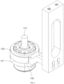
- a flow conveying mechanism 120 is provided on the outside of the friction stir tool 110.
- the flow conveying mechanism 120 includes a support member 130.
- the support member 130 includes a mounting bracket for providing on the friction stir device and a main body sleeve 121 provided on the mounting bracket.
- the friction stir tool 110 passes through the mounting bracket and the main body sleeve 121 in sequence, and the friction stir tool 110 is rotationally connected to the mounting bracket through the bearing, the relative axial distance between the friction stir tool 110 and the mounting bracket is limited by the axial limiting mechanism, thereby achieving radial and axial support of the friction stir tool 110.
- the axial limiting mechanism can adopt existing technology, such as a locking buckle, which will not be described in detail again herein.
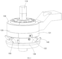
- the main body sleeve 121 is provided with an inlet channel 122 for delivering the coolant to the inlet 113 and an outlet channel 123 for receiving the coolant flowing out of the outlet 112.
- the inlet channel 122 can be connected to the water pump through the inlet pipe, so that the speed and opening of the water pump can be remotely controlled from a distance, thereby enabling remote temperature control.
- the coolant is transported from the inlet 113 to the cooling channel 111 through the inlet channel 122 to cool the stirring pin 115, and then discharged from the outlet 112 through the outlet channel 123.
- the coolant is water flow, and the temperature of the water flow does not exceed the ambient temperature, so as to form a large temperature difference with the friction stir tool 110 in friction stir operation, thereby improving the cooling efficiency of the friction stir tool 110.
- the friction stir tool cooling method also includes a sealing step: the inlet 113 is slidably sealed relative to the friction stir tool 110, and/or the outlet 112 is slidably sealed relative to the friction stir tool 110.
- a first support ring 124 is provided between the inlet channel 122 and the inlet 113, the inlet channel 122 is connected with the inlet 113 through the first support ring 124, a second support ring 125 is positioned between the outlet channel 123 and the outlet 112, and the outlet channel 123 is connected with the outlet 112 through the second support ring 125.
- the first support ring 124 and the second support ring 125 are fixed relative to the main body sleeve 121, but rotate relative to the friction stir tool 110.
- a first sealing member 1271 is provided between the first support ring 124 and the second support ring 125, and a second sealing member 1272 is provided on the upper part of the first support ring 124.
- a third sealing member 1273 is provided at the lower part of the second support ring 125, and a lower sealing cavity is formed between the third sealing member 1273 and the first sealing member 1271.
- the upper sealing cavity can be provided as the water inlet cavity
- the lower sealing cavity can be provided as the water outlet cavity.
- the coolant enters from the inlet channel 122, it is restricted between the first sealing member 1271 and the second sealing member 1272, and it can only enter the cooling channel 111.
- the coolant in the lower seal cavity is restricted between the first sealing member 1271 and the third sealing member 1273, it can only enter the outlet channel 123.
- the temperature in the lower sealing cavity is higher, because the coolant has passed through the stirring pin 115 and/or the shaft shoulder 114 and absorbed heat, therefore, the liquid with a higher temperature is prevented from leaking into the upper sealing cavity, which improves the cooling efficiency.
- a collection step is also included: the coolant flowing out from the outlet 112 is collected below the outlet 112.
- a chassis 128 is provided at the lower part of the flow conveying mechanism 120, the friction stir tool 110 passes through the chassis 128, and the chassis 128 is provided with a receiving cavity for collecting the coolant flowing out from the outlet 112.
- the coolant is transported into the cooling channel 111 through the inlet 113 to cool the stirring pin 115 and/or the shaft shoulder 114.
- the cooled coolant flows out from the outlet 112 to the receiving cavity of the chassis 128 for storage, which reduces the temperature at the shaft shoulder 114 and the stirring pin 115 of the friction stir tool 110.
- a flow-throwing step is also included: the coolant flowing out from the outlet 112 is thrown away from the outer wall of the friction stir tool 110 below the outlet 112.
- the outer wall of the friction stir tool 110 located below the outlet 112 is provided with a flow-throwing ring 129.
- the flow-throwing ring 129 is used to guide the coolant flowing out from the outlet 112 into the receiving cavity on the chassis 128, preventing the coolant flowing out from the outlet 112 from flowing along the outer wall of the friction stir tool 110 to the welding part and affecting the welding quality.
- the flow-throwing ring 129 is tilted downward from the inside to the outside, so that the coolant flowing out from the outlet 112 can flow along the flow-throwing ring 129 to the receiving cavity due to gravity.
- the friction stir tool cooling method further includes: the coolant flowing out from the outlet 112 is sucked away, and/or an inert gas is introduced to the lower end of the friction stir tool 110.
- the coolant flowing out from the outlet 112 can be sucked away by providing a water suction pipe 140 connected to the receiving cavity on the chassis 128.
- the water suction pipe 140 is used to suck the coolant in the receiving cavity.
- the water suction pipe 140 is connected to a pumping device such as a water pump to pump out the coolant in the receiving cavity.
- a gas pipe 150 facing the end of the friction stir tool 110 can be provided on the chassis 128, the friction stir tool 110 and the welded specimens are protected by introducing an inert gas into the end of the friction stir tool 110 through the gas pipe 150.
- Argon gas can be used as the inert gas.
- the temperature of the friction stir tool 110 can be detected by using an infrared temperature measurement device, the infrared temperature measurement device is connected to an external controller to send the detected temperature value to the controller in time, and the controller controls the opening of the water pump through the controller, which allows the flow rate of the coolant to be adjusted.
Landscapes
- Engineering & Computer Science (AREA)
- Mechanical Engineering (AREA)
- Pressure Welding/Diffusion-Bonding (AREA)
Applications Claiming Priority (2)
| Application Number | Priority Date | Filing Date | Title |
|---|---|---|---|
| CN202211247139.7A CN117381130A (zh) | 2022-10-12 | 2022-10-12 | 一种搅拌摩擦工具冷却方法 |
| PCT/CN2023/118606 WO2024078248A1 (zh) | 2022-10-12 | 2023-09-13 | 一种搅拌摩擦工具冷却方法 |
Publications (2)
| Publication Number | Publication Date |
|---|---|
| EP4556151A1 true EP4556151A1 (de) | 2025-05-21 |
| EP4556151A4 EP4556151A4 (de) | 2026-03-25 |
Family
ID=89470878
Family Applications (1)
| Application Number | Title | Priority Date | Filing Date |
|---|---|---|---|
| EP23876453.4A Pending EP4556151A4 (de) | 2022-10-12 | 2023-09-13 | Verfahren zum kühlen eines reibrührwerkzeugs |
Country Status (4)
| Country | Link |
|---|---|
| US (1) | US20250144739A1 (de) |
| EP (1) | EP4556151A4 (de) |
| CN (1) | CN117381130A (de) |
| WO (1) | WO2024078248A1 (de) |
Families Citing this family (9)
| Publication number | Priority date | Publication date | Assignee | Title |
|---|---|---|---|---|
| CN117340414A (zh) * | 2023-03-22 | 2024-01-05 | 澳门发展及质量研究所 | 一种固相成型加工方法 |
| US12172229B2 (en) | 2023-03-30 | 2024-12-24 | Blue Origin, Llc | Friction stir additive manufacturing devices and methods for forming in-situ rivets |
| US12246392B2 (en) | 2023-03-30 | 2025-03-11 | Blue Origin Manufacturing, LLC | Deposition head for friction stir additive manufacturing devices and methods |
| US12140109B2 (en) | 2023-03-30 | 2024-11-12 | Blue Origin, Llc | Transpiration-cooled systems having permeable and non-permeable portions |
| US12383975B2 (en) | 2023-08-03 | 2025-08-12 | Blue Origin Manufacturing, LLC | Friction stir additive manufacturing formed parts and structures with integrated passages |
| US12303994B2 (en) | 2023-08-03 | 2025-05-20 | Blue Origin Manufacturing, LLC | Friction stir additive manufacturing formed parts and structures with integrated passages |
| US12589446B2 (en) | 2023-12-12 | 2026-03-31 | Blue Origin Manufacturing, LLC | Wire-feed friction stir additive manufacturing systems, devices, and methods |
| CN119658107B (zh) * | 2025-02-20 | 2025-07-11 | 博格(江苏)金属科技有限公司 | 一种搅拌摩擦焊接装置的控制方法 |
| CN120362693B (zh) * | 2025-06-26 | 2025-08-29 | 北京世佳博科技集团有限公司 | 一种搅拌头温度控制方法、控制系统、介质及产品 |
Family Cites Families (20)
| Publication number | Priority date | Publication date | Assignee | Title |
|---|---|---|---|---|
| US6516992B1 (en) * | 1996-05-31 | 2003-02-11 | The Boeing Company | Friction stir welding with simultaneous cooling |
| US7121448B2 (en) * | 2003-08-29 | 2006-10-17 | General Electric Company | Friction stir welding apparatus and associated thermal management systems and methods |
| US7832613B2 (en) * | 2009-01-15 | 2010-11-16 | General Electric Company | Friction stir welding system |
| US20120080506A1 (en) * | 2010-09-23 | 2012-04-05 | Tecnara Fsw Company, Llc | Method for holding high speed friction spot joining tools |
| KR101230359B1 (ko) * | 2010-11-22 | 2013-02-21 | 주식회사 윈젠 | 마찰교반용접용 회전 공구 |
| JP5461476B2 (ja) * | 2011-05-27 | 2014-04-02 | 三菱重工業株式会社 | 摩擦攪拌接合装置 |
| DE102011106506A1 (de) * | 2011-06-15 | 2012-12-20 | Eurocopter Deutschland Gmbh | Schweißwerkzeug zum Verbinden von wenigstens zwei Werkstücken, Schweißverfahren und Werkstück |
| JP5945348B1 (ja) * | 2015-04-10 | 2016-07-05 | 株式会社日立パワーソリューションズ | 摩擦かく拌接合装置、及び、摩擦かく拌接合方法 |
| US10099314B2 (en) * | 2016-03-18 | 2018-10-16 | Toshiba Kikai Kabushiki Kaisha | Tool holder and machine tool |
| US10016838B2 (en) * | 2016-03-18 | 2018-07-10 | Toshiba Kikai Kabushiki Kaisha | Friction stir welding tool |
| JP6143915B1 (ja) * | 2016-04-28 | 2017-06-07 | 株式会社日立パワーソリューションズ | 摩擦攪拌接合装置 |
| CN106001907A (zh) * | 2016-07-26 | 2016-10-12 | 哈尔滨万洲焊接技术有限公司 | 一种具有冷却功能的搅拌摩擦焊焊具 |
| US20180161850A1 (en) * | 2016-12-08 | 2018-06-14 | GM Global Technology Operations LLC | Single-sided joining machine |
| CN106825905A (zh) * | 2017-02-23 | 2017-06-13 | 南京索菲智能装备有限公司 | 搅拌摩擦头水气联合冷却装置及方法 |
| JP2019025490A (ja) * | 2017-07-25 | 2019-02-21 | 日本軽金属株式会社 | 接合方法 |
| CN107470772B (zh) * | 2017-07-25 | 2019-05-07 | 北京赛福斯特技术有限公司 | 一种用于搅拌摩擦焊接的水冷搅拌头及水冷循环的方法 |
| CN109202262B (zh) * | 2017-09-07 | 2020-12-25 | 中国航空制造技术研究院 | 一种搅拌摩擦焊接的搅拌头水冷却结构及冷却方法 |
| US10456858B2 (en) * | 2018-03-30 | 2019-10-29 | Esab Ab | Welding head for friction stir welding |
| CN215238524U (zh) * | 2021-05-25 | 2021-12-21 | 孚斯威焊接科技(上海)有限公司 | 一种液冷搅拌摩擦焊工具夹持系统 |
| CN219336363U (zh) * | 2022-10-12 | 2023-07-14 | 澳门发展及质量研究所 | 一种搅拌摩擦焊接工具及搅拌摩擦工具总成 |
-
2022
- 2022-10-12 CN CN202211247139.7A patent/CN117381130A/zh active Pending
-
2023
- 2023-09-13 WO PCT/CN2023/118606 patent/WO2024078248A1/zh not_active Ceased
- 2023-09-13 EP EP23876453.4A patent/EP4556151A4/de active Pending
-
2025
- 2025-01-13 US US19/018,486 patent/US20250144739A1/en active Pending
Also Published As
| Publication number | Publication date |
|---|---|
| WO2024078248A1 (zh) | 2024-04-18 |
| EP4556151A4 (de) | 2026-03-25 |
| CN117381130A (zh) | 2024-01-12 |
| US20250144739A1 (en) | 2025-05-08 |
Similar Documents
| Publication | Publication Date | Title |
|---|---|---|
| EP4556151A1 (de) | Verfahren zum kühlen eines reibrührwerkzeugs | |
| CN219336363U (zh) | 一种搅拌摩擦焊接工具及搅拌摩擦工具总成 | |
| CN105921878B (zh) | 一种复合产热的搅拌摩擦焊具 | |
| CN106903398B (zh) | 一种真空/保护气氛下组合热源焊接方法及其装置 | |
| CN112077322B (zh) | 钢管外壁旋压半固态金属粉末成型双金属复合管装置 | |
| US12337409B2 (en) | Friction stir welding apparatus and method | |
| CN106624281A (zh) | 一种采用cmt技术制备钢铝异种金属搭接接头的方法 | |
| CN107363392B (zh) | 一种可约束摩擦堆焊飞边的装置及材料表面堆焊方法 | |
| CN106884086A (zh) | 一种双边火焰加热法去除埋弧管焊缝残余应力的装置及工艺 | |
| CN101618483A (zh) | 旋转摩擦钎焊的方法 | |
| CN111421223A (zh) | 一种用于异种材料的搅拌摩擦对接焊装置及其加工方法 | |
| CN111906431A (zh) | 一种基于智能搅拌的增等材融合制造设备以及方法 | |
| CN103433616A (zh) | 一种搅拌摩擦焊装置 | |
| US20250144741A1 (en) | Solid-phase molding processing method | |
| CN105904083B (zh) | 一种电阻辅热的搅拌摩擦焊具 | |
| CN114515886A (zh) | 大尺寸异形不锈钢管道及其高效增材制造装置和方法 | |
| CN215880580U (zh) | 一种用于圆形管件的立式焊接工装 | |
| CN116021143A (zh) | 一种铜或铝管型母线环缝搅拌摩擦焊接装置及其焊接方法 | |
| Yang et al. | Effect of assembling clearance on welding characteristics of laser-MIG hybrid welding for aluminum alloy extrusions | |
| CN216966618U (zh) | 一种内置倒吸式油雾润滑冷却装置的搅拌摩擦焊机 | |
| CN206561207U (zh) | 一种小口径管材的激光切割装置 | |
| CN217096296U (zh) | 自动焊接边梁设备的气体保护焊机构 | |
| CN111922519A (zh) | 一种激光焊接装置 | |
| CN211219137U (zh) | 一种用于静轴肩搅拌摩擦焊接工具的便携连杆结构 | |
| CN108296625A (zh) | 一种基于搅拌摩擦焊的异种厚度球墨铸铁连接方法 |
Legal Events
| Date | Code | Title | Description |
|---|---|---|---|
| STAA | Information on the status of an ep patent application or granted ep patent |
Free format text: STATUS: THE INTERNATIONAL PUBLICATION HAS BEEN MADE |
|
| PUAI | Public reference made under article 153(3) epc to a published international application that has entered the european phase |
Free format text: ORIGINAL CODE: 0009012 |
|
| STAA | Information on the status of an ep patent application or granted ep patent |
Free format text: STATUS: REQUEST FOR EXAMINATION WAS MADE |
|
| 17P | Request for examination filed |
Effective date: 20250213 |
|
| AK | Designated contracting states |
Kind code of ref document: A1 Designated state(s): AL AT BE BG CH CY CZ DE DK EE ES FI FR GB GR HR HU IE IS IT LI LT LU LV MC ME MK MT NL NO PL PT RO RS SE SI SK SM TR |
|
| DAV | Request for validation of the european patent (deleted) | ||
| DAX | Request for extension of the european patent (deleted) | ||
| A4 | Supplementary search report drawn up and despatched |
Effective date: 20260225 |
|
| RIC1 | Information provided on ipc code assigned before grant |
Ipc: B23K 20/12 20060101AFI20260219BHEP Ipc: B23K 37/003 20250101ALN20260219BHEP |