EP4556097A1 - Carbon dioxide capture system - Google Patents
Carbon dioxide capture system Download PDFInfo
- Publication number
- EP4556097A1 EP4556097A1 EP22951170.4A EP22951170A EP4556097A1 EP 4556097 A1 EP4556097 A1 EP 4556097A1 EP 22951170 A EP22951170 A EP 22951170A EP 4556097 A1 EP4556097 A1 EP 4556097A1
- Authority
- EP
- European Patent Office
- Prior art keywords
- carbon dioxide
- recycle
- fluid
- route
- capture system
- Prior art date
- Legal status (The legal status is an assumption and is not a legal conclusion. Google has not performed a legal analysis and makes no representation as to the accuracy of the status listed.)
- Pending
Links
Images





Classifications
-
- C—CHEMISTRY; METALLURGY
- C01—INORGANIC CHEMISTRY
- C01B—NON-METALLIC ELEMENTS; COMPOUNDS THEREOF; METALLOIDS OR COMPOUNDS THEREOF NOT COVERED BY SUBCLASS C01C
- C01B32/00—Carbon; Compounds thereof
- C01B32/50—Carbon dioxide
-
- B—PERFORMING OPERATIONS; TRANSPORTING
- B01—PHYSICAL OR CHEMICAL PROCESSES OR APPARATUS IN GENERAL
- B01D—SEPARATION
- B01D53/00—Separation of gases or vapours; Recovering vapours of volatile solvents from gases; Chemical or biological purification of waste gases, e.g. engine exhaust gases, smoke, fumes, flue gases, aerosols
- B01D53/34—Chemical or biological purification of waste gases
- B01D53/46—Removing components of defined structure
- B01D53/62—Carbon oxides
-
- B—PERFORMING OPERATIONS; TRANSPORTING
- B01—PHYSICAL OR CHEMICAL PROCESSES OR APPARATUS IN GENERAL
- B01D—SEPARATION
- B01D53/00—Separation of gases or vapours; Recovering vapours of volatile solvents from gases; Chemical or biological purification of waste gases, e.g. engine exhaust gases, smoke, fumes, flue gases, aerosols
- B01D53/02—Separation of gases or vapours; Recovering vapours of volatile solvents from gases; Chemical or biological purification of waste gases, e.g. engine exhaust gases, smoke, fumes, flue gases, aerosols by adsorption, e.g. preparative gas chromatography
- B01D53/04—Separation of gases or vapours; Recovering vapours of volatile solvents from gases; Chemical or biological purification of waste gases, e.g. engine exhaust gases, smoke, fumes, flue gases, aerosols by adsorption, e.g. preparative gas chromatography with stationary adsorbents
- B01D53/0462—Temperature swing adsorption
-
- B—PERFORMING OPERATIONS; TRANSPORTING
- B01—PHYSICAL OR CHEMICAL PROCESSES OR APPARATUS IN GENERAL
- B01D—SEPARATION
- B01D53/00—Separation of gases or vapours; Recovering vapours of volatile solvents from gases; Chemical or biological purification of waste gases, e.g. engine exhaust gases, smoke, fumes, flue gases, aerosols
- B01D53/02—Separation of gases or vapours; Recovering vapours of volatile solvents from gases; Chemical or biological purification of waste gases, e.g. engine exhaust gases, smoke, fumes, flue gases, aerosols by adsorption, e.g. preparative gas chromatography
- B01D53/06—Separation of gases or vapours; Recovering vapours of volatile solvents from gases; Chemical or biological purification of waste gases, e.g. engine exhaust gases, smoke, fumes, flue gases, aerosols by adsorption, e.g. preparative gas chromatography with moving adsorbents, e.g. rotating beds
-
- B—PERFORMING OPERATIONS; TRANSPORTING
- B01—PHYSICAL OR CHEMICAL PROCESSES OR APPARATUS IN GENERAL
- B01D—SEPARATION
- B01D2253/00—Adsorbents used in seperation treatment of gases and vapours
- B01D2253/10—Inorganic adsorbents
- B01D2253/102—Carbon
-
- B—PERFORMING OPERATIONS; TRANSPORTING
- B01—PHYSICAL OR CHEMICAL PROCESSES OR APPARATUS IN GENERAL
- B01D—SEPARATION
- B01D2253/00—Adsorbents used in seperation treatment of gases and vapours
- B01D2253/10—Inorganic adsorbents
- B01D2253/104—Alumina
-
- B—PERFORMING OPERATIONS; TRANSPORTING
- B01—PHYSICAL OR CHEMICAL PROCESSES OR APPARATUS IN GENERAL
- B01D—SEPARATION
- B01D2253/00—Adsorbents used in seperation treatment of gases and vapours
- B01D2253/10—Inorganic adsorbents
- B01D2253/106—Silica or silicates
-
- B—PERFORMING OPERATIONS; TRANSPORTING
- B01—PHYSICAL OR CHEMICAL PROCESSES OR APPARATUS IN GENERAL
- B01D—SEPARATION
- B01D2253/00—Adsorbents used in seperation treatment of gases and vapours
- B01D2253/10—Inorganic adsorbents
- B01D2253/106—Silica or silicates
- B01D2253/108—Zeolites
-
- B—PERFORMING OPERATIONS; TRANSPORTING
- B01—PHYSICAL OR CHEMICAL PROCESSES OR APPARATUS IN GENERAL
- B01D—SEPARATION
- B01D2253/00—Adsorbents used in seperation treatment of gases and vapours
- B01D2253/25—Coated, impregnated or composite adsorbents
-
- B—PERFORMING OPERATIONS; TRANSPORTING
- B01—PHYSICAL OR CHEMICAL PROCESSES OR APPARATUS IN GENERAL
- B01D—SEPARATION
- B01D2257/00—Components to be removed
- B01D2257/50—Carbon oxides
- B01D2257/504—Carbon dioxide
-
- B—PERFORMING OPERATIONS; TRANSPORTING
- B01—PHYSICAL OR CHEMICAL PROCESSES OR APPARATUS IN GENERAL
- B01D—SEPARATION
- B01D2258/00—Sources of waste gases
- B01D2258/06—Polluted air
-
- B—PERFORMING OPERATIONS; TRANSPORTING
- B01—PHYSICAL OR CHEMICAL PROCESSES OR APPARATUS IN GENERAL
- B01D—SEPARATION
- B01D2259/00—Type of treatment
- B01D2259/40—Further details for adsorption processes and devices
- B01D2259/40083—Regeneration of adsorbents in processes other than pressure or temperature swing adsorption
- B01D2259/40088—Regeneration of adsorbents in processes other than pressure or temperature swing adsorption by heating
- B01D2259/4009—Regeneration of adsorbents in processes other than pressure or temperature swing adsorption by heating using hot gas
-
- B—PERFORMING OPERATIONS; TRANSPORTING
- B01—PHYSICAL OR CHEMICAL PROCESSES OR APPARATUS IN GENERAL
- B01D—SEPARATION
- B01D2259/00—Type of treatment
- B01D2259/45—Gas separation or purification devices adapted for specific applications
- B01D2259/4508—Gas separation or purification devices adapted for specific applications for cleaning air in buildings
-
- Y—GENERAL TAGGING OF NEW TECHNOLOGICAL DEVELOPMENTS; GENERAL TAGGING OF CROSS-SECTIONAL TECHNOLOGIES SPANNING OVER SEVERAL SECTIONS OF THE IPC; TECHNICAL SUBJECTS COVERED BY FORMER USPC CROSS-REFERENCE ART COLLECTIONS [XRACs] AND DIGESTS
- Y02—TECHNOLOGIES OR APPLICATIONS FOR MITIGATION OR ADAPTATION AGAINST CLIMATE CHANGE
- Y02C—CAPTURE, STORAGE, SEQUESTRATION OR DISPOSAL OF GREENHOUSE GASES [GHG]
- Y02C20/00—Capture or disposal of greenhouse gases
- Y02C20/40—Capture or disposal of greenhouse gases of CO2
Definitions
- the present invention relates to a carbon dioxide capture system.
- Patent Document 1 discloses technology for directly capturing carbon dioxide from air (Direct Air Capture).
- Patent Document 1 Japanese Unexamined Patent Application, First Publication JP 2021- 169079 A
- One embodiment of a carbon dioxide capture system includes a supply route that guides air, a carbon dioxide capture portion that has a processing region, which causes a sorbent to adsorb carbon dioxide present in the air, and a recycle region that recycles the sorbent using a recycle fluid, an extraction route that guides the air having a reduced concentration of carbon dioxide using the processing region, a recycle route that guides the recycle fluid to the recycle region, a circulation route that guides a recycle discharge fluid that is discharged by recycling the sorbent using the recycle fluid, and a carbon dioxide separator that obtains the recycle fluid by separating at least a portion of the carbon dioxide from the recycle discharge fluid.
- FIG. 1 is a schematic diagram that shows a system for capturing carbon dioxide in a first embodiment.
- a carbon dioxide capture system 1 includes a supply route 2, a carbon dioxide capture portion 3, an extraction route 4, a recycle route 5, a circulation route 6, a carbon dioxide separator 7, a heat pump unit (heat exchange unit) 8, an introduction route 9, a compressor 10, and a reducer 11.
- the supply route 2 is connected to a processing region 31 of the carbon dioxide capture portion 3.
- the supply route 2 guides fluid such as outside air or the like (fluid to be processed) to the processing region 31.
- a blower 21 is provided so as to supply air to the processing region 31 in the supply route 2.
- the carbon dioxide capture portion 3 includes a first region 31A and a second region 32A.
- the first region 31A is the processing region 31.
- the second region 32A is a recycle region 32.
- the processing region 31 for example, includes a sorbent, and a receptacle that stores the sorbent.
- the recycle region 32 for example, includes the sorbent to be recycled, and a receptacle that houses said sorbent.
- the sorbent As an example of the sorbent, amines, silica gel, zeolite, activated carbon, diatomaceous earth, alumina or the like may be mentioned. Specifically, by causing the sorbent to adsorb carbon dioxide that is present in the air, it is possible to separate carbon dioxide from other components.
- the sorbent may be in granular, or in powder form, or the like. Granular form includes beads (spherical), pellets (cylindrical), or the like.
- the sorbent When using powder form sorbent, the sorbent may be carried by surface of a base material.
- the base material may have a honeycomb shape.
- the recycle region 32 recycles the sorbent that has adsorbed carbon dioxide at the processing region 31 using the recycle fluid F1.
- the recycle region 32 has a function of detaching the carbon dioxide from the sorbent.
- the recycle region 32 for example, has a heating device that heats the sorbent.
- the heating device separates carbon dioxide from the sorbent by heating the sorbent in the presence of the recycle fluid F1. By separating carbon dioxide from the sorbent, it is possible to recycle the sorbent.
- the recycle fluid F1 that includes carbon dioxide separated from the sorbent is discharged from the recycle region 32 as a "recycle discharge fluid F2".
- the recycle region 32 may include a pressure reducer of a pressure reduction pump or the like. It is possible to encourage separation of the carbon dioxide from the sorbent by placing the sorbent in a state of reduced pressure.
- the extraction route 4 is connected to the processing region 31.
- the extraction route 4 supplies air that has a reduced concentration of carbon dioxide using the processing region 31, to a living space 100 (space being supplied).
- the recycle route 5 is connected to the recycle region 32 of the carbon dioxide capture portion 3, and to the carbon dioxide separator 7.
- the recycle route 5 guides the recycle fluid F1 from the carbon dioxide separator 7 to the recycle region 32.
- Nitrogen (N 2 ), hydrogen (H 2 ), methane or the like may be mentioned as the recycle fluid F1.
- the circulation route 6 is connected to the recycle region 32 of the carbon dioxide capture portion 3, and to the carbon dioxide separator 7.
- the circulation route 6 guides the recycle discharge fluid F2 that is discharged from the recycle region 32 to the carbon dioxide separator 7.
- the carbon dioxide separator 7 separates at least a portion of the carbon dioxide present in the recycle discharge fluid F2, using separation methods such as liquefied separation, membrane separation, sorbent separation or the like. One method, or a combination of two or more methods out of the aforementioned separation methods may be adopted in the carbon dioxide separator 7.
- the carbon dioxide separator 7 uses liquefied separation, for example, a specific component is liquefied and separated from another component (gaseous). Specifically, for example, carbon dioxide at high pressure and low temperature is liquefied and separated from the other component (gas).
- membrane separation for example, a separation membrane that allows small sized atoms of a component to pass through is used to separate a specific component from other components.
- a separation membrane where carbon dioxide is selectively allowed to pass through is used.
- carbon dioxide is separated from a liquid that includes a mixture of carbon dioxide and other components (nitrogen, hydrogen, methane or the like).
- organic membranes dendrimer membrane or the like
- non-organic membranes zeolite membrane, silica membrane, carbon membrane or the like
- a sorbent is made to capture a specific component.
- amines, silica gel, zeolite, activated carbon, diatomaceous earth, alumina or the like may be mentioned.
- recycle discharge fluid F2 which has a reduced concentration of carbon dioxide, passes through the recycle route 5, and is guided out from the carbon dioxide separator 7 as the "recycle fluid F1".
- the heat pump unit 8 includes a heater (first heat exchanger) 81, an expander 82, a cooler (second heat exchanger) 83, a compressor 84, and a circulation route 85.
- the heater 81 heats the recycle fluid F1 by exchanging heat with a heat transfer fluid F3.
- the expander 82 decreases a pressure of the heat transfer fluid F3.
- the cooler 83 cools the recycle discharge fluid F2 by exchanging heat with the heat transfer fluid F3.
- the compressor 84 increases the pressure of the heat transfer fluid F3.
- the heater 81, the expander 82, the cooler 83, and the compressor 84 are provided on the circulation route 85.
- the circulation route 85 is a circular route.
- the circulation route 85 circulates the heat transfer fluid F3.
- the heat transfer fluid F3 circulates so as to go through the heater 81, the expander 82, the cooler 83, and the compressor 84 in such order.
- carbon dioxide used as the heat transfer fluid F3, by applying an appropriate heating temperature (for example, 90 °C to 120 °C) using the heater 81, and an appropriate cooling temperature (for example, -30 °C to -20 °C) using the cooler 83, to the existing heat pump unit 8.
- an appropriate heating temperature for example, 90 °C to 120 °C
- an appropriate cooling temperature for example, -30 °C to -20 °C
- the heat pump unit 8 may configure an air conditioner.
- the air conditioner may conduct either of a cooling or heating operation using heat absorption or heat release of the heat transfer fluid F3.
- the heater 81 for example, is installed on either one of an indoor unit, or an outdoor unit.
- the cooler 83 for example, is installed on either one of the indoor unit or the outdoor unit.
- the heat pump unit 8 may configure a refrigeration and freezing device.
- the refrigeration and freezing device cools using the cooler 83, by using heat absorption of the heat transfer fluid F3.
- the introduction route 9 is connected to the supply route 2.
- the introduction route 9 introduces air of the indoor environment that is discharged from the living space 100 into the supply route 2.
- the compressor 10 is provided on the circulation route 6.
- the compressor 10 increases a pressure of the recycle discharge fluid F2.
- the reducer 11 is provided on the recycle route 5.
- the reducer 11 decreases the pressure of the recycle fluid F1.
- a cooler may be provided on a downstream side of the compressor 10 in order to decrease a temperature of the recycle discharge fluid F2, which increases due to the compressor 10 raising the pressure thereof.
- a process where the carbon dioxide is removed by adsorbing at least a portion thereof is known as an "adsorption step", in the processing region 31.
- the adsorbed carbon dioxide that is adsorbed by the sorbent at the processing region 31, is recycled in the recycle region 32.
- the carbon dioxide is separated from the sorbent in the presence of the recycle fluid F1.
- the recycle fluid F1 that includes the carbon dioxide separated from the sorbent is discharged as the "recycle discharge fluid F2" from the recycle region 32.
- recycle step The process of reusing the sorbent in the recycle region 32 is known as a "recycle step".
- the recycle region 32 when reusing the sorbent having carbon dioxide adsorbed at the processing region 31, it is possible to switch over the sorbent between the processing region 31 and the recycle region 32. For example, the sorbent of the processing region 31 along with the receptacle thereof is moved to the recycle region 32, and the sorbent recycled at the recycle region 32 along with the receptacle thereof is moved to the processing region 31. As such, it is possible to switch over between the processing region and the recycle region.
- the first region 31A (left portion on FIG. 1 ) of the carbon dioxide capture portion 3 is the processing region 31.
- the supply route 2 and the extraction route 4 are connected to the first region 31A.
- the second region 32A (right portion on FIG. 1 ) is the recycle region 32.
- the recycle route 5 and the circulation route 6 are connected to the second region 32A.
- the supply route 2 and the extraction route 4 are connected to the second region 32A using valve operations provided on branching routes, which are not shown on the drawings.
- the recycle route 5 and the circulation route 6 are connected to the first region 31A. With such operation, the first region 31A becomes the recycle region.
- the second region 32A becomes the processing region. As such, it is possible to switch over between the processing region and the recycle region. Due to valve operations, it is also possible to return the first region 31A back to being the processing region. It is also possible to return the second region 32A back to the recycle region.
- the recycle discharge fluid F2 passes through the circulation route 6, and is guided from the recycle region 32.
- the pressure of the recycle discharge fluid F2 is increased by the compressor 10.
- the recycle discharge fluid F2 is cooled by exchanging heat with the heat transfer fluid F3 in the cooler 83.
- the cooler 83 it is possible for the cooler 83 to cool down the recycle discharge fluid F2 in the carbon dioxide separator 7, to a temperature of the recycle discharge fluid F2 that corresponds to specifications of the carbon dioxide separator 7, to be mentioned later on.
- the recycle discharge fluid F2 is guided to the carbon dioxide separator 7.
- the carbon dioxide separator 7 separates at least a portion of the carbon dioxide present in the recycle discharge fluid F2, using separation methods such as liquefied separation, membrane separation, sorbent separation or the like. Condensed carbon dioxide passes through a capture route 71, and is collected.
- the recycle discharge fluid F2 having a reduced concentration of carbon dioxide passes through the recycle route 5, and is guided from the carbon dioxide separator 7 as the "recycle fluid F1".
- the recycle fluid F1 is heated by exchanging heat with the heat transfer fluid F3, at the heater 81. It is possible for the heater 81 for example, to heat the recycle fluid F1 to a temperature between 90 °C and 120 °C of the recycle fluid F1, in the recycle region 32. The pressure of the recycle fluid F1 is reduced as needed, at the reducer 11. The recycle fluid F1 passes through the recycle route 5, and is guided to the recycle region 32.
- the heat transfer fluid F3 circulates within the circulation route 85, in the heat pump unit 8.
- the heat transfer fluid F3 is cooled by exchanging heat with the recycle fluid F1 in the heater 81.
- the pressure of the heat transfer fluid F3 is reduced at the expander 82.
- the heat transfer fluid F3 is heated by exchanging heat with the recycle discharge fluid F2 in the cooler 83.
- the heat transfer fluid F3 heads towards the heater 81 after having a pressure thereof increased by the compressor 84. As such, the heat transfer fluid F3 conducts heating of the recycle fluid F1 and cooling of the recycle discharge fluid F2.
- the carbon dioxide capture system 1 includes the circulation route 6 that guides the recycle discharge fluid F2 from the recycle region 32, and the carbon dioxide separator 7 that generates the recycle fluid F1 having a reduced concentration of carbon dioxide from the recycle discharge fluid F2. Since the carbon dioxide capture system 1 circulates the recycle fluid F1, it is possible for the carbon dioxide capture system 1 to increase carbon dioxide capturing efficiency in the carbon dioxide separator 7.
- the carbon dioxide capture system 1 circulates both the recycle fluid F1 and the recycle discharge fluid F2, it is possible for the carbon dioxide capture system 1 to effectively use heat energy that is held by the recycle fluid F1 and the recycle discharge fluid F2. Therefore, it is possible to increase an energy efficiency of the overall system.
- the carbon dioxide capture system 1 captures carbon dioxide from the air using the carbon dioxide capture portion 3, and guides the recycle discharge fluid F2 that includes the carbon dioxide to the carbon dioxide separator 7, it is possible for the carbon dioxide capture system 1 to increase the carbon dioxide capturing efficiency.
- the carbon dioxide capture system 1 includes the compressor 10, the heater 81, and the cooler 83.
- the recycle fluid F1 By heating the recycle fluid F1 and making a temperature of an inside of the recycle region 32 appropriate, it is possible for the heater 81 to efficiently conduct recycling of the sorbent.
- the heater 81 heats the recycle fluid F1 by exchanging heat with the heat transfer fluid F3.
- the cooler 83 cools the recycle discharge fluid F2 by exchanging heat with the heat transfer fluid F3. Since the carbon dioxide capture system 1 conducts heat exchange with both the recycle fluid F1 and the recycle discharge fluid F2 via the shared heat transfer fluid F3, it is possible for the carbon dioxide capture system 1 to increase the energy efficiency.
- the carbon dioxide separator 7 that uses liquefied separation it is possible for the carbon dioxide separator 7 that uses liquefied separation to efficiently separate carbon dioxide. With the carbon dioxide separator 7 that uses liquefied separation, it is possible to downsize equipment thereof, since it is possible to downsize a volume of the captured carbon dioxide by liquefaction.
- the carbon dioxide separator 7 that uses membrane separation it is possible for the carbon dioxide separator 7 that uses membrane separation to efficiently separate carbon dioxide.
- the carbon dioxide separator 7 that uses membrane separation compared to other separation methods, there are few constraints on pressure, temperature or the like. As such, it is possible to suppress energy use due to pressurization, depressurization, or the like. Therefore, it is possible to capture carbon dioxide at low cost.
- carbon dioxide used as the heat transfer fluid F3 by applying an appropriate heating temperature (for example, 90 °C to 120 °C) by the heater 81, and an appropriate cooling temperature (for example, -30 °C to -20 °C) by the cooler 83, to the existing heat pump unit 8. As such, it is possible to configure a low cost carbon dioxide capture system 1.
- an appropriate heating temperature for example, 90 °C to 120 °C
- an appropriate cooling temperature for example, -30 °C to -20 °C
- the heater 81 and the cooler 83 may at least configure an air conditioner.
- the air conditioner uses the heater 81 and the cooler 83 to construct the carbon dioxide capture system 1, compared to a case where an exclusive heater and cooler are used, it is possible to achieve such construction at low cost.
- the heater 81 and the cooler 83 may at least configure a refrigeration and freezing device.
- the refrigeration and freezing device uses the heater 81 and the cooler 83 to construct the carbon dioxide capture system 1, compared to a case where an exclusive heater and cooler are used, it is possible to achieve such construction at low cost.
- the heater 81 and the cooler 83 may configure both an air conditioner and a refrigeration and freezing device.
- a carbon dioxide capture system according to a second embodiment is explained. Since the carbon dioxide capture system according to the second embodiment is similar to the carbon dioxide capture system of the first embodiment, mainly aspects which differ from the first embodiment are explained. As for configurations that are similar to configurations of the first embodiment, the same reference symbols are affixed thereto, with explanations thereof being omitted.
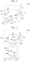
- FIG. 2 is a schematic diagram that shows a portion of a system for capturing carbon dioxide, according to the second embodiment.
- a carbon dioxide capture system 101 includes a heat pump unit 108, in place of the heat pump unit 8 (refer to FIG. 1 ).
- the heat pump unit 108 differs from the heat pump unit 8 (refer to FIG. 1 ) in an aspect of including a plurality of compressors 184A and 184B, in place of the compressor 84 (refer to FIG. 1 ).
- the compressors 184A and 184B are provided on the circulation route 85.
- the compressor 184A is a first compressor 184A.
- the compressor 184B is a second compressor 184B.
- the second compressor 184B is on a downstream side flow direction of the heat transfer fluid F3, with respect to the first compressor 184A.
- the first compressor 184A and the second compressor 184B are disposed in series on the circulation route 85.
- the carbon dioxide capture system 101 it is possible for the carbon dioxide capture system 101 to increase the pressure of the heat transfer fluid F3, since the carbon dioxide capture system 101 has the heat pump unit 108, which includes the plurality of compressors 184A and 184B. As such, it is possible to expand an operational range of heating and cooling at the heat pump unit 108. Thus, it is possible to increase functionality of the carbon dioxide capture system, and it is possible to capture carbon dioxide more efficiently.
- a number of compressors of the heat pump unit 108 is two, the number of compressors thereof is not limited to two. A plurality (an optional number greater than or equal to two) of compressors may be used.
- FIG. 3 is a schematic diagram that shows a portion of a system for capturing carbon dioxide, according to a third embodiment.
- a carbon dioxide capture system 201 includes a heat pump unit 208, in place of the heat pump unit 8 (refer to FIG. 1 ).
- the heater 281 heats the recycle fluid F1 by exchanging heat with a first heat transfer fluid F3A.
- the first expander 282 decreases a pressure of the first heat transfer fluid F3A.
- the intermediate heat exchanger 287 cools a second heat transfer fluid F3B by exchanging heat with the first heat transfer fluid F3A.
- the first compressor 284 increases the pressure of the first heat transfer fluid F3A.
- the heater 281, the first expander 282, the intermediate heat exchanger 287, and the first compressor 284 are provided on the first circulation route 285.
- the first circulation route 285 is a pathway for circulation.
- the first circulation route 285 circulates the first heat transfer fluid F3A so as to go through the heater 281, the first expander 282, the intermediate heat exchanger 287, and the first compressor 284 in such order.
- the second expander 288 decreases a pressure of the second heat transfer fluid F3B.
- the cooler 283 cools the recycle discharge fluid F2 by exchanging heat with the second heat transfer fluid F3B.
- the second compressor 289 increases the pressure of the second heat transfer fluid F3B.
- the intermediate heat exchanger 287, the second expander 288, the cooler 283, and the second compressor 289 are provided on the second circulation route 290.
- the second circulation route 290 is a circulation pathway.
- the second circulation route 290 circulates the second heat transfer fluid F3B so as to go through the intermediate heat exchanger 287, the second expander 288, the cooler 283, and the second compressor 289 in such order.
- the first heat transfer fluid F3A and the second heat transfer fluid F3B have differing physical properties such as boiling points or the like.
- first heat transfer fluid F3A for example, carbon dioxide or the like may be mentioned.
- second heat transfer fluid F3B for example, an alternative fluorocarbon or the like may be mentioned.
- the second heat transfer fluid F3B is for example operated at a lower temperature, compared to the first transfer fluid F3A.
- a portion (first portion) through which the first heat transfer fluid F3A flows is for example, used to construct a heat pump of a water heater.
- the first portion for example, includes the heater 281, the first expander 282, the first compressor 284, and the first circulation route 285.
- a portion (second portion) through which the second heat transfer fluid F3B flows is for example, used to construct a heat pump of a refrigeration and freezing device.
- the second portion for example, includes the second expander 288, the cooler 283, the second compressor 289, and the second circulation route 290.
- the intermediate heat exchanger 287 is included in one out of the first portion or the second portion.
- the carbon dioxide capture system 201 includes the heater 281, the intermediate heat exchanger 287, the cooler 283, and the heat pump unit 208. Since the first heat transfer fluid F3A and the second heat transfer fluid F3B are used in the heat pump unit 208, it is possible to expand the operational range heating and cooling. Thus, it is possible to increase functionality of the carbon dioxide capture system, and it is possible to capture carbon dioxide more efficiently.
- FIG. 4 is a schematic diagram that shows a system for capturing carbon dioxide, according to a fourth embodiment.
- a carbon dioxide capture system 301 differs from the carbon dioxide capture system 1 (refer to FIG. 1 ) in an aspect of having an air cleaner 312 provided on the introduction route 9.
- the air cleaner 312 for example, cleans out the air by collecting suspended particulate matter of pollen, dust, viruses, mold, germs, house dust, smoke, odors, volatile chemical substances or the like.
- the air cleaner 312 for example, captures suspended particulate matter using a capturing filter.
- the air cleaner 312 may include an electric field generator that creates an electric field in between electrodes thereof. The electric field generator kills, or causes pollen, viruses, mold, bacteria or the like to become inactive.
- the carbon dioxide capture system 301 includes the air cleaner 312, it is possible to have indoor air that is discharged from the living space 100 cleaned and guided to the supply route 2. Thus, it is possible to increase a degree of cleanliness of the air that is supplied to the living space 100. Since air that is supplied to the carbon dioxide capture portion 3 is cleaned, it is possible for the carbon dioxide capture system 301 to increase the carbon dioxide capturing efficiency in the carbon dioxide capture portion 3.
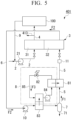
- FIG. 5 is a schematic diagram that shows a system for capturing carbon dioxide, according to a fifth embodiment.
- the carbon dioxide capture system 401 differs from the carbon dioxide capture system 1 (refer to FIG. 1 ) in an aspect of having an exhaust route 413 connected to the extraction route 4. It is possible for the exhaust route 413 to discharge a portion of the air that flows through the extraction route 4 to the outside. Gas that is discharged from the exhaust route 413 for example, is released to the atmosphere.
- the carbon dioxide capture system 401 By discharging a portion of the air that flows through the extraction route 4 from the exhaust route 413, it is possible for the carbon dioxide capture system 401 to introduce outside air from the supply route 2. By conducting air exchange via discharge and introduction, it is possible to increase the cleanliness of the air of the living space 100. Since the carbon dioxide capture system 401 discharges gas to the atmosphere from the exhaust route 413 after carbon dioxide is captured, it is possible to keep the amount of carbon dioxide being discharged to a minimum. The aforementioned is preferable from a point of view of environmental safety.
- FIG. 6 is a schematic diagram that shows a system for capturing carbon dioxide, according to a sixth embodiment.
- a carbon dioxide capture system 501 differs from the carbon dioxide capture system 1 (refer to FIG. 1 ) in an aspect of having the air cleaner 312 provided on the introduction route 9, and of the exhaust route 413 being connected to the extraction route 4.
- the carbon dioxide capture system 501 includes the air cleaner 312, it is possible to introduce clean air to the supply route 2. Since the carbon dioxide capture system 501 includes the exhaust route 413, it is possible to conduct air exchange. Thus, it is possible to increase the cleanliness of the air of the living space 100. Since the carbon dioxide capture system 501 discharges gas to the atmosphere from the exhaust route 413 after carbon dioxide is captured, it is possible to keep the amount of carbon dioxide being discharged to a minimum. The aforementioned is preferable from a point of view of environmental safety.
- FIG. 7 is a schematic diagram that shows a system for capturing carbon dioxide, according to a seventh embodiment.
- a carbon dioxide capture system 601 includes a carbon dioxide capture portion 603, in place of the carbon dioxide capture portion 3 (refer to FIG. 1 ).
- the carbon dioxide capture portion 603 includes the first processing region 31, a second processing region 633, and the recycle region 32.
- the first processing region 31 has the same configuration as the processing region 31 (refer to FIG. 1 ).
- the second processing region 633 also includes a sorbent.
- the sorbent of the second processing region 633 is the same sorbent as a sorbent of the first processing region 31.
- the second processing region 633 is connected to the introduction route 9.
- the introduction route 9 guides the air that is discharged from the living space 100 to the second processing region 633.
- the second processing region 633 removes at least a portion of the carbon dioxide present in the air using adsorption. Air having a reduced concentration of carbon dioxide is passed through an exhaust route 634, and is discharged to the outside from the second processing region 633.
- the carbon dioxide capture system 601 Since the carbon dioxide capture system 601 has the second processing region 633, it is possible for the carbon dioxide capture system 601 to capture carbon dioxide present in the air that is discharged from the living space 100. Thus, it is possible to increase the carbon dioxide capturing efficiency thereof.
- the carbon dioxide capture system 601 air that is discharged from the living space 100 is not reused, and is discharged to the outside, passing through the exhaust route 634. As such, it is possible to reduce a risk of airborne or droplet infection, or from viruses or the like. It is also possible to increase the cleanliness of the air inside the living space 100. Since the carbon dioxide capture system 601 discharges gas to the atmosphere from the exhaust route 413 after carbon dioxide is captured, it is possible to keep the amount of carbon dioxide being discharged to a minimum. The aforementioned is preferable from a point of view of environmental safety.
- FIG. 8 is a schematic diagram that shows a system for capturing carbon dioxide, according to an eighth embodiment.
- a carbon dioxide capture system 701 differs from the carbon dioxide capture system 601 (refer to FIG. 7 ) in an aspect of having a heat exchanger 714 provided.
- the heat exchanger 714 is provided so as to straddle the extraction route 4 and the introduction route 9.
- the heat exchanger 714 conducts heat exchange and humidity exchange between the air that is supplied to the living space 100 using the extraction route 4, and the air that is guided from the living space 100 using the introduction route 9. It is possible for the heat exchanger 714 to have the temperature and the humidity of the air being supplied to the living space 100 correspond to an environment inside of the living space 100.
- the carbon dioxide capture system 701 includes the heat exchanger 714, it is possible for the carbon dioxide capture system 701 to adjust the temperature of the air that passes through the extraction route 4 and is supplied to the living space 100, and to appropriate said temperature and humidity, by exchanging heat with the exhaust air. Thus, it is possible to increase energy efficiency.
- FIG. 9 is a schematic diagram that shows a system for capturing carbon dioxide, according to the ninth embodiment.
- the carbon dioxide separator 7 is a liquefied separator that separates carbon dioxide using liquefied separation. Since the carbon dioxide separator 7 is a liquefied separator, high pressure and low temperature are required.
- the recycle discharge fluid F2 is pressurized using the compressor 10. A temperature of the recycle discharge fluid F2 is lowered using the cooler 83. Temperature and pressure conditions for liquefying carbon dioxide are for example, temperatures of -20 °C to -30 °C, and a pressure of 2 MPa.
- the carbon dioxide capture system 801 includes a cooler 815.
- the cooler 815 is provided downstream of the compressor 10 in the circulation route 6.
- the cooler 815 for example, is provided between the compressor 10 and the cooler 83.
- the cooler 815 for example, is a water-cooled cooler.
- the cooler 815 cools the recycle discharge fluid F2 by exchanging heat with the cooler (water).
- the pressure of the recycle discharge fluid F2 increases due to being pressurized by the compressor 10, and the cooler 815 decreases the temperature of the reuse discharge fluid F2 decreases. Thus, it is possible to decrease the load of the cooler 83.
- the carbon dioxide separator 7 liquefies and separates at least a portion of the carbon dioxide that is present in the reuse discharge fluid F2 that passes through the cooler 83. Concentrated carbon dioxide that passes through the capture route 71 is captured.
- the carbon dioxide capture system 801 uses liquefied separation, it is possible to efficiently conduct separation of the carbon dioxide. Since it is possible to downsize a volume of the carbon dioxide by liquefying, it is possible to downsize a volume of an apparatus of the carbon dioxide capture system 801.
- cooler 815 that uses a water-cooled cooling method
- a cooling method thereof is not limited thereto.
- a method of cooling by passing the recycle fluid F1 may be adopted. Accordingly, by having the recycle fluid F1 be heated, it is possible to achieve a system having high thermal efficiency.
- FIG. 10 is a schematic diagram that shows a system for capturing carbon dioxide, according to a tenth embodiment.
- a carbon dioxide separator 907 is a membrane separator that separates carbon dioxide using membrane separation.
- the carbon dioxide separator 907 for example, includes a separation membrane that selectively permeates carbon dioxide.
- the carbon dioxide separator 907 separates at least a portion of the carbon dioxide present in the recycle discharge fluid F2, using the separation membrane. Concentrated carbon dioxide is captured passing through the capture route 71.
- the carbon dioxide capture system 901 adopts a separation membrane, it is possible to efficiently conduct separation of the carbon dioxide. Compared to cases where other separation methods are adopted, the carbon dioxide capture system 901 has less constraints on pressure and temperature. Therefore, it is possible to suppress the amount of energy used for pressurizing and cooling, making it possible to capture carbon dioxide at low cost.
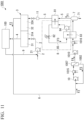
- FIG. 11 is a schematic diagram that shows a system for capturing carbon dioxide, according to an eleventh embodiment.
- both liquefied separation and membrane separation are adopted as separation methods of carbon dioxide in the carbon dioxide separator.
- the carbon dioxide capture system 1001 includes the supply route 2, the carbon dioxide capture portion 3, the extraction route 4, the recycle route 5, the circulation route 6, the heat pump unit 8, the introduction route 9, the first compressor 10, a first cooler 1015, a first carbon dioxide separator 1007, a return route 1002, a second compressor 1010, a second cooler 1016, the second carbon dioxide separator 7, and the reducer 11.
- the first carbon dioxide separator 1007 and the second carbon dioxide separator 7, are examples of carbon dioxide separators.
- the carbon dioxide capture system 1001 differs from the carbon dioxide capture system 1 (refer to FIG. 1 ) in an aspect of including the first cooler 1015, the first carbon dioxide separator 1007, the return route 1002, the second compressor 1010, and the second cooler 1016.
- the first cooler 1015 and the second cooler 1016 for example, is a water-cooled cooler.
- the first cooler 1015 and the second cooler 1016 cool working fluids thereof by exchanging heat with a refrigerant (water).
- the first carbon dioxide separator 1007 is a membrane separator.
- the first carbon dioxide separator 1007 for example, has a separation membrane that selectively permeates carbon dioxide.
- the second carbon dioxide separator 7 is a liquefied separator.
- the return route 1002 is connected to an exit of a non-permeable side of the first carbon dioxide separator 1007, and to the circulation route 6 (located on an upstream side of the first compressor 10).
- the recycle discharge fluid F2 is cooled by the first cooler 1015 and is guided to the first carbon dioxide separator 1007, after having a pressure thereof raised by the compressor 10, in the carbon dioxide capture system 1001.
- the carbon dioxide present in the recycle discharge fluid F2 is concentrated using the first carbon dioxide separator 1007.
- a non-permeable side fluid F5 that does not permeate through the separation membrane of the first carbon dioxide separator 1007 is returned to the circulation route 6 (located on the upstream side, more than the first compressor 10), using the return route 1002. Accordingly, it is possible to increase the carbon dioxide capturing efficiency in the first carbon dioxide separator 1007.
- the permeable side fluid F4 is cooled using the second cooler 1016 and the cooler 83, and is guided to the second carbon dioxide separator 7, after having a pressure thereof increased using the second compressor 1010.
- the second carbon dioxide separator 7 separates at least a portion of the carbon dioxide present in the permeable side fluid F4.
- the concentrated carbon dioxide is captured passing through the capture route 71.
- the carbon dioxide capture system 1001 it is possible for the carbon dioxide capture system 1001 to increase the carbon dioxide capturing efficiency by adopting both liquefied separation and membrane separation.
- first cooler 1015 and the second cooler 1016 are explained as water-cooled coolers, both coolers are not limited to water-cooled coolers, and cooling where the recycle fluid F1 is circulated may be adopted. Accordingly, by heating the recycle fluid F1, it is possible to achieve a more thermal efficient system.
- FIG. 12 is a schematic diagram that shows a system for capturing carbon dioxide, according to a twelfth embodiment.
- a carbon dioxide capture system 1101 differs from the carbon dioxide capture system 1001 (refer to FIG. 11 ) in an aspect of having a return route 1102 in place of the return route 1002 (refer to FIG. 11 ).
- the return route 1102 is connected to the exit of a non-permeable side of the first carbon dioxide separator 1007, and to the recycle route 5 (located on the upstream side more than the heater 81).
- the non-permeable side fluid F5 that is guided from the first carbon dioxide separator 1007 is guided to the recycle route 5 using the return route 1102.
- the non-permeable side fluid F5 is used as a part of the recycle fluid F1.
- the carbon dioxide capture system 1101 it is possible for the carbon dioxide capture system 1101 to increase the carbon dioxide capture efficiency by adopting both liquefied separation and membrane separation. Since the carbon dioxide capture system 1101 conducts membrane separation before liquefied separation, it is possible for the system to suppress energy needed for cooling during liquefied separation. Thus, it is possible to capture carbon dioxide at low cost.
- the non-permeable side fluid F5 having a decreased concentration of carbon dioxide is used as the recycle fluid F1, it is possible to increase the energy efficiency thereof.
- concentrators may be provided on the circulation route 6.
- a concentrator for example, increases the concentration of carbon dioxide in the recycle discharge fluid F2 by using separation methods such as liquefied separation, membrane separation, sorbent separation or the like.
- the concentrator may be provided on the supply route 2.
- the reducer 11 is provided on the downstream side of the heater 81, the reducer 11 is not limited to such configuration, and may be provided on the upstream side of the heater 81, according to system equipment specifications.
- heat exchanger it is possible to use a known heater, cooler, intermediate heat exchanger or the like.
- a heat exchanger for example, a multi-tube heat exchanger, a plate heat exchanger, a coil heat exchanger, a double tube heat exchanger, and a spiral heat exchanger or the like may be used.
Landscapes
- Chemical & Material Sciences (AREA)
- Engineering & Computer Science (AREA)
- Chemical Kinetics & Catalysis (AREA)
- Analytical Chemistry (AREA)
- General Chemical & Material Sciences (AREA)
- Oil, Petroleum & Natural Gas (AREA)
- Organic Chemistry (AREA)
- Health & Medical Sciences (AREA)
- Environmental & Geological Engineering (AREA)
- Biomedical Technology (AREA)
- Inorganic Chemistry (AREA)
- Separation Of Gases By Adsorption (AREA)
- Carbon And Carbon Compounds (AREA)
Abstract
Description
- The present invention relates to a carbon dioxide capture system.
-
Patent Document 1 discloses technology for directly capturing carbon dioxide from air (Direct Air Capture). - Patent Document 1: Japanese Unexamined Patent Application, First Publication
JP 2021- 169079 A - In the technology mentioned above, a problem of decreasing efficiency of capturing carbon dioxide exists.
- The present invention has been made in order to address the problem above, and an object is to provide a system for capturing carbon dioxide that is capable of increasing capture efficiency of carbon dioxide.
- One embodiment of a carbon dioxide capture system according to the present embodiment includes a supply route that guides air, a carbon dioxide capture portion that has a processing region, which causes a sorbent to adsorb carbon dioxide present in the air, and a recycle region that recycles the sorbent using a recycle fluid, an extraction route that guides the air having a reduced concentration of carbon dioxide using the processing region, a recycle route that guides the recycle fluid to the recycle region, a circulation route that guides a recycle discharge fluid that is discharged by recycling the sorbent using the recycle fluid, and a carbon dioxide separator that obtains the recycle fluid by separating at least a portion of the carbon dioxide from the recycle discharge fluid.
- According to the present invention, it is possible to provide a system for capturing carbon dioxide that is capable of increasing capture efficiency of carbon dioxide.
-
-
FIG. 1 A schematic diagram that shows a system for capturing carbon dioxide, according to a first embodiment. -
FIG. 2 A schematic diagram that shows a portion of a system for capturing carbon dioxide, according to a second embodiment. -
FIG. 3 A schematic diagram that shows a portion of a system for capturing carbon dioxide, according to a third embodiment. -
FIG. 4 A schematic diagram that shows a system for capturing carbon dioxide, according to a fourth embodiment. -
FIG. 5 A schematic diagram that shows a system for capturing carbon dioxide, according to a fifth embodiment. -
FIG. 6 A schematic diagram that shows a system for capturing carbon dioxide, according to a sixth embodiment. -
FIG. 7 A schematic diagram that shows a system for capturing carbon dioxide, according to a seventh embodiment. -
FIG. 8 A schematic diagram that shows a system for capturing carbon dioxide, according to an eighth embodiment. -
FIG. 9 A schematic diagram that shows a system for capturing carbon dioxide, according to a ninth embodiment. -
FIG. 10 A schematic diagram that shows a system for capturing carbon dioxide, according to a tenth embodiment. -
FIG. 11 A schematic diagram that shows a system for capturing carbon dioxide, according to an eleventh embodiment. -
FIG. 12 A schematic diagram that shows a system for capturing carbon dioxide, according to a twelfth embodiment. - Hereinafter, embodiments of the present invention are explained with reference to the drawings. The scope of the present invention is not limited to the embodiments below, and may be changed so long as the embodiments do not depart from the technical scope of the present invention.
-
FIG. 1 is a schematic diagram that shows a system for capturing carbon dioxide in a first embodiment. - As shown in
FIG. 1 , a carbondioxide capture system 1 includes asupply route 2, a carbondioxide capture portion 3, anextraction route 4, arecycle route 5, acirculation route 6, acarbon dioxide separator 7, a heat pump unit (heat exchange unit) 8, anintroduction route 9, acompressor 10, and areducer 11. - The
supply route 2 is connected to aprocessing region 31 of the carbondioxide capture portion 3. Thesupply route 2 guides fluid such as outside air or the like (fluid to be processed) to theprocessing region 31. For example, ablower 21 is provided so as to supply air to theprocessing region 31 in thesupply route 2. - The carbon
dioxide capture portion 3 includes afirst region 31A and asecond region 32A. In the example shown inFIG. 1 , thefirst region 31A is theprocessing region 31. Thesecond region 32A is arecycle region 32. Theprocessing region 31 for example, includes a sorbent, and a receptacle that stores the sorbent. Therecycle region 32 for example, includes the sorbent to be recycled, and a receptacle that houses said sorbent. - As an example of the sorbent, amines, silica gel, zeolite, activated carbon, diatomaceous earth, alumina or the like may be mentioned. Specifically, by causing the sorbent to adsorb carbon dioxide that is present in the air, it is possible to separate carbon dioxide from other components. The sorbent may be in granular, or in powder form, or the like. Granular form includes beads (spherical), pellets (cylindrical), or the like. When using powder form sorbent, the sorbent may be carried by surface of a base material. The base material may have a honeycomb shape.
- Since at least a portion of carbon dioxide present in the air is removed using adsorption, it is possible to obtain air having a reduced concentration of carbon dioxide in the
processing region 31. - The
recycle region 32 recycles the sorbent that has adsorbed carbon dioxide at theprocessing region 31 using the recycle fluid F1. Therecycle region 32 has a function of detaching the carbon dioxide from the sorbent. Therecycle region 32 for example, has a heating device that heats the sorbent. The heating device separates carbon dioxide from the sorbent by heating the sorbent in the presence of the recycle fluid F1. By separating carbon dioxide from the sorbent, it is possible to recycle the sorbent. The recycle fluid F1 that includes carbon dioxide separated from the sorbent, is discharged from therecycle region 32 as a "recycle discharge fluid F2". - The
recycle region 32 may include a pressure reducer of a pressure reduction pump or the like. It is possible to encourage separation of the carbon dioxide from the sorbent by placing the sorbent in a state of reduced pressure. - The
extraction route 4 is connected to theprocessing region 31. Theextraction route 4 supplies air that has a reduced concentration of carbon dioxide using theprocessing region 31, to a living space 100 (space being supplied). - The
recycle route 5 is connected to therecycle region 32 of the carbondioxide capture portion 3, and to thecarbon dioxide separator 7. Therecycle route 5 guides the recycle fluid F1 from thecarbon dioxide separator 7 to therecycle region 32. Nitrogen (N2), hydrogen (H2), methane or the like may be mentioned as the recycle fluid F1. - The
circulation route 6 is connected to therecycle region 32 of the carbondioxide capture portion 3, and to thecarbon dioxide separator 7. Thecirculation route 6 guides the recycle discharge fluid F2 that is discharged from therecycle region 32 to thecarbon dioxide separator 7. - The
carbon dioxide separator 7 separates at least a portion of the carbon dioxide present in the recycle discharge fluid F2, using separation methods such as liquefied separation, membrane separation, sorbent separation or the like. One method, or a combination of two or more methods out of the aforementioned separation methods may be adopted in thecarbon dioxide separator 7. - When the
carbon dioxide separator 7 uses liquefied separation, for example, a specific component is liquefied and separated from another component (gaseous). Specifically, for example, carbon dioxide at high pressure and low temperature is liquefied and separated from the other component (gas). - When
carbon dioxide separator 7 uses membrane separation, for example, a separation membrane that allows small sized atoms of a component to pass through is used to separate a specific component from other components. Specifically for example, a separation membrane where carbon dioxide is selectively allowed to pass through is used. In such separation membrane, carbon dioxide is separated from a liquid that includes a mixture of carbon dioxide and other components (nitrogen, hydrogen, methane or the like).
As examples of membranes used in membrane separation, organic membranes (dendrimer membrane or the like), and non-organic membranes (zeolite membrane, silica membrane, carbon membrane or the like) may be mentioned. - When
carbon dioxide separator 7 uses sorbent separation, for example, a sorbent is made to capture a specific component. As a sorbent, amines, silica gel, zeolite, activated carbon, diatomaceous earth, alumina or the like may be mentioned. Specifically, for example, it is possible to separate carbon dioxide from other components by having carbon dioxide be adsorbed by the sorbent. - By having the carbon dioxide be separated, recycle discharge fluid F2, which has a reduced concentration of carbon dioxide, passes through the
recycle route 5, and is guided out from thecarbon dioxide separator 7 as the "recycle fluid F1". - The
heat pump unit 8 includes a heater (first heat exchanger) 81, anexpander 82, a cooler (second heat exchanger) 83, acompressor 84, and acirculation route 85. - The
heater 81 heats the recycle fluid F1 by exchanging heat with a heat transfer fluid F3. - The
expander 82 decreases a pressure of the heat transfer fluid F3. - The cooler 83 cools the recycle discharge fluid F2 by exchanging heat with the heat transfer fluid F3.
- The
compressor 84 increases the pressure of the heat transfer fluid F3. - The
heater 81, theexpander 82, the cooler 83, and thecompressor 84 are provided on thecirculation route 85. - The
circulation route 85 is a circular route. Thecirculation route 85 circulates the heat transfer fluid F3. The heat transfer fluid F3 circulates so as to go through theheater 81, theexpander 82, the cooler 83, and thecompressor 84 in such order. As the heat transfer fluid F3, carbon dioxide, an alternative fluorocarbon, propane, dimethyl ether or the like may be mentioned. - It is possible to have carbon dioxide used as the heat transfer fluid F3, by applying an appropriate heating temperature (for example, 90 °C to 120 °C) using the
heater 81, and an appropriate cooling temperature (for example, -30 °C to -20 °C) using the cooler 83, to the existingheat pump unit 8. - The
heat pump unit 8 for example, may configure an air conditioner. The air conditioner may conduct either of a cooling or heating operation using heat absorption or heat release of the heat transfer fluid F3. Theheater 81 for example, is installed on either one of an indoor unit, or an outdoor unit. The cooler 83 for example, is installed on either one of the indoor unit or the outdoor unit. - The
heat pump unit 8 for example, may configure a refrigeration and freezing device. The refrigeration and freezing device cools using the cooler 83, by using heat absorption of the heat transfer fluid F3. - The
introduction route 9 is connected to thesupply route 2. Theintroduction route 9 introduces air of the indoor environment that is discharged from the livingspace 100 into thesupply route 2. - The
compressor 10 is provided on thecirculation route 6. Thecompressor 10 increases a pressure of the recycle discharge fluid F2. - The
reducer 11 is provided on therecycle route 5. Thereducer 11 decreases the pressure of the recycle fluid F1. - A cooler may be provided on a downstream side of the
compressor 10 in order to decrease a temperature of the recycle discharge fluid F2, which increases due to thecompressor 10 raising the pressure thereof. - Next, an example of a carbon dioxide capture system using the carbon
dioxide capture system 1 is explained. - Outside air or the like is guided to the
processing region 31 of the carbondioxide capture portion 3 using thesupply route 2. In theprocessing region 31, by causing the sorbent to adsorb the carbon dioxide that is present in the air, at least a portion of the carbon dioxide is removed. Air having reduced carbon dioxide concentration is guided to the living space (space being supplied) 100 using theextraction route 4. - A process where the carbon dioxide is removed by adsorbing at least a portion thereof is known as an "adsorption step", in the
processing region 31. - The adsorbed carbon dioxide that is adsorbed by the sorbent at the
processing region 31, is recycled in therecycle region 32. Specifically, in therecycle region 32, the carbon dioxide is separated from the sorbent in the presence of the recycle fluid F1. By separating the carbon dioxide, the sorbent is recycled. The recycle fluid F1 that includes the carbon dioxide separated from the sorbent is discharged as the "recycle discharge fluid F2" from therecycle region 32. - The process of reusing the sorbent in the
recycle region 32 is known as a "recycle step". - A switchover from the processing region to the recycle region in the carbon
dioxide capture portion 3 is explained. - In the
recycle region 32, when reusing the sorbent having carbon dioxide adsorbed at theprocessing region 31, it is possible to switch over the sorbent between theprocessing region 31 and therecycle region 32. For example, the sorbent of theprocessing region 31 along with the receptacle thereof is moved to therecycle region 32, and the sorbent recycled at therecycle region 32 along with the receptacle thereof is moved to theprocessing region 31. As such, it is possible to switch over between the processing region and the recycle region. - When the sorbent is switched over, it is possible to extract the sorbent of the
processing region 31 from the receptacle moving the sorbent to therecycle region 32, along with extracting the sorbent recycled at therecycle region 32 and moving the sorbent to theprocessing region 31. - By changing routes thereof, it is possible to switch over between the processing region and the recycle region. In
FIG. 1 , thefirst region 31A (left portion onFIG. 1 ) of the carbondioxide capture portion 3 is theprocessing region 31. Thesupply route 2 and theextraction route 4 are connected to thefirst region 31A. Thesecond region 32A (right portion onFIG. 1 ) is therecycle region 32. Therecycle route 5 and thecirculation route 6 are connected to thesecond region 32A. - The
supply route 2 and theextraction route 4 are connected to thesecond region 32A using valve operations provided on branching routes, which are not shown on the drawings. Therecycle route 5 and thecirculation route 6 are connected to thefirst region 31A. With such operation, thefirst region 31A becomes the recycle region. Thesecond region 32A becomes the processing region. As such, it is possible to switch over between the processing region and the recycle region. Due to valve operations, it is also possible to return thefirst region 31A back to being the processing region. It is also possible to return thesecond region 32A back to the recycle region. - The recycle discharge fluid F2 passes through the
circulation route 6, and is guided from therecycle region 32. The pressure of the recycle discharge fluid F2 is increased by thecompressor 10. The recycle discharge fluid F2 is cooled by exchanging heat with the heat transfer fluid F3 in the cooler 83. For example, it is possible for the cooler 83 to cool down the recycle discharge fluid F2 in thecarbon dioxide separator 7, to a temperature of the recycle discharge fluid F2 that corresponds to specifications of thecarbon dioxide separator 7, to be mentioned later on. - The recycle discharge fluid F2 is guided to the
carbon dioxide separator 7. - The
carbon dioxide separator 7 separates at least a portion of the carbon dioxide present in the recycle discharge fluid F2, using separation methods such as liquefied separation, membrane separation, sorbent separation or the like. Condensed carbon dioxide passes through acapture route 71, and is collected. - By having the carbon dioxide be separated, the recycle discharge fluid F2 having a reduced concentration of carbon dioxide passes through the
recycle route 5, and is guided from thecarbon dioxide separator 7 as the "recycle fluid F1". - The recycle fluid F1 is heated by exchanging heat with the heat transfer fluid F3, at the
heater 81. It is possible for theheater 81 for example, to heat the recycle fluid F1 to a temperature between 90 °C and 120 °C of the recycle fluid F1, in therecycle region 32. The pressure of the recycle fluid F1 is reduced as needed, at thereducer 11. The recycle fluid F1 passes through therecycle route 5, and is guided to therecycle region 32. - The heat transfer fluid F3 circulates within the
circulation route 85, in theheat pump unit 8. The heat transfer fluid F3 is cooled by exchanging heat with the recycle fluid F1 in theheater 81. The pressure of the heat transfer fluid F3 is reduced at theexpander 82. The heat transfer fluid F3 is heated by exchanging heat with the recycle discharge fluid F2 in the cooler 83. The heat transfer fluid F3 heads towards theheater 81 after having a pressure thereof increased by thecompressor 84. As such, the heat transfer fluid F3 conducts heating of the recycle fluid F1 and cooling of the recycle discharge fluid F2. - The carbon
dioxide capture system 1 includes thecirculation route 6 that guides the recycle discharge fluid F2 from therecycle region 32, and thecarbon dioxide separator 7 that generates the recycle fluid F1 having a reduced concentration of carbon dioxide from the recycle discharge fluid F2. Since the carbondioxide capture system 1 circulates the recycle fluid F1, it is possible for the carbondioxide capture system 1 to increase carbon dioxide capturing efficiency in thecarbon dioxide separator 7. - Since the carbon
dioxide capture system 1 circulates both the recycle fluid F1 and the recycle discharge fluid F2, it is possible for the carbondioxide capture system 1 to effectively use heat energy that is held by the recycle fluid F1 and the recycle discharge fluid F2. Therefore, it is possible to increase an energy efficiency of the overall system. - Since the carbon
dioxide capture system 1 captures carbon dioxide from the air using the carbondioxide capture portion 3, and guides the recycle discharge fluid F2 that includes the carbon dioxide to thecarbon dioxide separator 7, it is possible for the carbondioxide capture system 1 to increase the carbon dioxide capturing efficiency. - The carbon
dioxide capture system 1 includes thecompressor 10, theheater 81, and the cooler 83. By heating the recycle fluid F1 and making a temperature of an inside of therecycle region 32 appropriate, it is possible for theheater 81 to efficiently conduct recycling of the sorbent. By increasing the pressure of the recycle discharge fluid F2, it is possible for thecompressor 10 to efficiently conduct separation of the carbon dioxide in thecarbon dioxide separator 7. By cooling the recycle discharge fluid F2 and making a temperature of an inside of thecarbon dioxide separator 7 appropriate, it is possible for the cooler 83 to efficiently conduct separation of the carbon dioxide. - Since it is possible for the carbon
dioxide capture system 1 to achieve downsize of a volume of the recycle discharge fluid F2 using thecompressor 10 and the cooler 83, it is possible to downsize equipment thereof. - The
heater 81 heats the recycle fluid F1 by exchanging heat with the heat transfer fluid F3. The cooler 83 cools the recycle discharge fluid F2 by exchanging heat with the heat transfer fluid F3. Since the carbondioxide capture system 1 conducts heat exchange with both the recycle fluid F1 and the recycle discharge fluid F2 via the shared heat transfer fluid F3, it is possible for the carbondioxide capture system 1 to increase the energy efficiency. - It is possible for the
carbon dioxide separator 7 that uses liquefied separation to efficiently separate carbon dioxide. With thecarbon dioxide separator 7 that uses liquefied separation, it is possible to downsize equipment thereof, since it is possible to downsize a volume of the captured carbon dioxide by liquefaction. - It is possible for the
carbon dioxide separator 7 that uses membrane separation to efficiently separate carbon dioxide. With thecarbon dioxide separator 7 that uses membrane separation, compared to other separation methods, there are few constraints on pressure, temperature or the like. As such, it is possible to suppress energy use due to pressurization, depressurization, or the like. Therefore, it is possible to capture carbon dioxide at low cost. - It is possible to have carbon dioxide used as the heat transfer fluid F3, by applying an appropriate heating temperature (for example, 90 °C to 120 °C) by the
heater 81, and an appropriate cooling temperature (for example, -30 °C to -20 °C) by the cooler 83, to the existingheat pump unit 8. As such, it is possible to configure a low cost carbondioxide capture system 1. - The
heater 81 and the cooler 83 may at least configure an air conditioner. In such case, since the air conditioner uses theheater 81 and the cooler 83 to construct the carbondioxide capture system 1, compared to a case where an exclusive heater and cooler are used, it is possible to achieve such construction at low cost. - The
heater 81 and the cooler 83 may at least configure a refrigeration and freezing device. In such case, since the refrigeration and freezing device uses theheater 81 and the cooler 83 to construct the carbondioxide capture system 1, compared to a case where an exclusive heater and cooler are used, it is possible to achieve such construction at low cost. - The
heater 81 and the cooler 83 may configure both an air conditioner and a refrigeration and freezing device. - Next, a carbon dioxide capture system according to a second embodiment is explained. Since the carbon dioxide capture system according to the second embodiment is similar to the carbon dioxide capture system of the first embodiment, mainly aspects which differ from the first embodiment are explained. As for configurations that are similar to configurations of the first embodiment, the same reference symbols are affixed thereto, with explanations thereof being omitted.
-
FIG. 2 is a schematic diagram that shows a portion of a system for capturing carbon dioxide, according to the second embodiment. - As shown in
FIG. 2 , a carbondioxide capture system 101 includes aheat pump unit 108, in place of the heat pump unit 8 (refer toFIG. 1 ). Theheat pump unit 108 differs from the heat pump unit 8 (refer toFIG. 1 ) in an aspect of including a plurality ofcompressors FIG. 1 ). Thecompressors circulation route 85. Thecompressor 184A is afirst compressor 184A. Thecompressor 184B is asecond compressor 184B. Thesecond compressor 184B is on a downstream side flow direction of the heat transfer fluid F3, with respect to thefirst compressor 184A. Thefirst compressor 184A and thesecond compressor 184B are disposed in series on thecirculation route 85. - It is possible for the carbon
dioxide capture system 101 to increase the pressure of the heat transfer fluid F3, since the carbondioxide capture system 101 has theheat pump unit 108, which includes the plurality ofcompressors heat pump unit 108. Thus, it is possible to increase functionality of the carbon dioxide capture system, and it is possible to capture carbon dioxide more efficiently. - In the carbon
dioxide capture system 101 shown inFIG. 2 , although a number of compressors of theheat pump unit 108 is two, the number of compressors thereof is not limited to two. A plurality (an optional number greater than or equal to two) of compressors may be used. - Next, a carbon dioxide capture system according to a third embodiment is explained. Due to similarities with carbon dioxide capture systems of other embodiments, the same reference symbols are affixed thereto, with explanations thereof being omitted.
-
FIG. 3 is a schematic diagram that shows a portion of a system for capturing carbon dioxide, according to a third embodiment. - As shown in
FIG. 3 , a carbondioxide capture system 201 includes aheat pump unit 208, in place of the heat pump unit 8 (refer toFIG. 1 ). - The
heat pump unit 208 includes a heater (first heat exchanger) 281, afirst expander 282, anintermediate heat exchanger 287, afirst compressor 284,first circulation route 285, asecond expander 288, a cooler (second heat exchanger) 283, asecond compressor 289, and asecond circulation route 290. - The
heater 281 heats the recycle fluid F1 by exchanging heat with a first heat transfer fluid F3A. - The
first expander 282 decreases a pressure of the first heat transfer fluid F3A. - The
intermediate heat exchanger 287 cools a second heat transfer fluid F3B by exchanging heat with the first heat transfer fluid F3A. - The
first compressor 284 increases the pressure of the first heat transfer fluid F3A. - The
heater 281, thefirst expander 282, theintermediate heat exchanger 287, and thefirst compressor 284 are provided on thefirst circulation route 285. - The
first circulation route 285 is a pathway for circulation. Thefirst circulation route 285 circulates the first heat transfer fluid F3A so as to go through theheater 281, thefirst expander 282, theintermediate heat exchanger 287, and thefirst compressor 284 in such order. - The
second expander 288 decreases a pressure of the second heat transfer fluid F3B. - The cooler 283 cools the recycle discharge fluid F2 by exchanging heat with the second heat transfer fluid F3B.
- The
second compressor 289 increases the pressure of the second heat transfer fluid F3B. - The
intermediate heat exchanger 287, thesecond expander 288, the cooler 283, and thesecond compressor 289 are provided on thesecond circulation route 290. - The
second circulation route 290 is a circulation pathway. Thesecond circulation route 290 circulates the second heat transfer fluid F3B so as to go through theintermediate heat exchanger 287, thesecond expander 288, the cooler 283, and thesecond compressor 289 in such order. - The first heat transfer fluid F3A and the second heat transfer fluid F3B have differing physical properties such as boiling points or the like. As the first heat transfer fluid F3A for example, carbon dioxide or the like may be mentioned. As the second heat transfer fluid F3B for example, an alternative fluorocarbon or the like may be mentioned. The second heat transfer fluid F3B is for example operated at a lower temperature, compared to the first transfer fluid F3A.
- Out of the
heat pump unit 208, a portion (first portion) through which the first heat transfer fluid F3A flows is for example, used to construct a heat pump of a water heater. The first portion for example, includes theheater 281, thefirst expander 282, thefirst compressor 284, and thefirst circulation route 285. - Out of the
heat pump unit 208, a portion (second portion) through which the second heat transfer fluid F3B flows is for example, used to construct a heat pump of a refrigeration and freezing device. The second portion for example, includes thesecond expander 288, the cooler 283, thesecond compressor 289, and thesecond circulation route 290. - The
intermediate heat exchanger 287 is included in one out of the first portion or the second portion. - The carbon
dioxide capture system 201 includes theheater 281, theintermediate heat exchanger 287, the cooler 283, and theheat pump unit 208. Since the first heat transfer fluid F3A and the second heat transfer fluid F3B are used in theheat pump unit 208, it is possible to expand the operational range heating and cooling. Thus, it is possible to increase functionality of the carbon dioxide capture system, and it is possible to capture carbon dioxide more efficiently. - Next, a carbon dioxide capture system according to a fourth embodiment is explained. Due to similarities with carbon dioxide capture systems of other embodiments, the same reference symbols are affixed thereto, with explanations thereof being omitted.
-
FIG. 4 is a schematic diagram that shows a system for capturing carbon dioxide, according to a fourth embodiment. - As shown in
FIG. 4 , a carbondioxide capture system 301 differs from the carbon dioxide capture system 1 (refer toFIG. 1 ) in an aspect of having anair cleaner 312 provided on theintroduction route 9. - The
air cleaner 312 for example, cleans out the air by collecting suspended particulate matter of pollen, dust, viruses, mold, germs, house dust, smoke, odors, volatile chemical substances or the like. Theair cleaner 312 for example, captures suspended particulate matter using a capturing filter. Theair cleaner 312 may include an electric field generator that creates an electric field in between electrodes thereof. The electric field generator kills, or causes pollen, viruses, mold, bacteria or the like to become inactive. - Since the carbon
dioxide capture system 301 includes theair cleaner 312, it is possible to have indoor air that is discharged from the livingspace 100 cleaned and guided to thesupply route 2. Thus, it is possible to increase a degree of cleanliness of the air that is supplied to theliving space 100. Since air that is supplied to the carbondioxide capture portion 3 is cleaned, it is possible for the carbondioxide capture system 301 to increase the carbon dioxide capturing efficiency in the carbondioxide capture portion 3. - Next, a carbon dioxide capture system according to a fifth embodiment is explained. Due to similarities with carbon dioxide capture systems of other embodiments, the same reference symbols are affixed thereto, with explanations thereof being omitted.
-
FIG. 5 is a schematic diagram that shows a system for capturing carbon dioxide, according to a fifth embodiment. - As shown in
FIG. 5 , the carbondioxide capture system 401 differs from the carbon dioxide capture system 1 (refer toFIG. 1 ) in an aspect of having anexhaust route 413 connected to theextraction route 4. It is possible for theexhaust route 413 to discharge a portion of the air that flows through theextraction route 4 to the outside. Gas that is discharged from theexhaust route 413 for example, is released to the atmosphere. - By discharging a portion of the air that flows through the
extraction route 4 from theexhaust route 413, it is possible for the carbondioxide capture system 401 to introduce outside air from thesupply route 2. By conducting air exchange via discharge and introduction, it is possible to increase the cleanliness of the air of theliving space 100. Since the carbondioxide capture system 401 discharges gas to the atmosphere from theexhaust route 413 after carbon dioxide is captured, it is possible to keep the amount of carbon dioxide being discharged to a minimum. The aforementioned is preferable from a point of view of environmental safety. - Next, a carbon dioxide capture system according to a sixth embodiment is explained. Due to similarities with carbon dioxide capture systems of other embodiments, the same reference symbols are affixed thereto, with explanations thereof being omitted.
-
FIG. 6 is a schematic diagram that shows a system for capturing carbon dioxide, according to a sixth embodiment. - As shown in
FIG. 6 , a carbondioxide capture system 501 differs from the carbon dioxide capture system 1 (refer toFIG. 1 ) in an aspect of having theair cleaner 312 provided on theintroduction route 9, and of theexhaust route 413 being connected to theextraction route 4. - Since the carbon
dioxide capture system 501 includes theair cleaner 312, it is possible to introduce clean air to thesupply route 2. Since the carbondioxide capture system 501 includes theexhaust route 413, it is possible to conduct air exchange. Thus, it is possible to increase the cleanliness of the air of theliving space 100. Since the carbondioxide capture system 501 discharges gas to the atmosphere from theexhaust route 413 after carbon dioxide is captured, it is possible to keep the amount of carbon dioxide being discharged to a minimum. The aforementioned is preferable from a point of view of environmental safety. - Next, a carbon dioxide capture system according to a seventh embodiment is explained. Due to similarities with carbon dioxide capture systems of other embodiments, the same reference symbols are affixed thereto, with explanations thereof being omitted.
-
FIG. 7 is a schematic diagram that shows a system for capturing carbon dioxide, according to a seventh embodiment. - As shown in
FIG. 7 , a carbondioxide capture system 601 includes a carbondioxide capture portion 603, in place of the carbon dioxide capture portion 3 (refer toFIG. 1 ). The carbondioxide capture portion 603 includes thefirst processing region 31, asecond processing region 633, and therecycle region 32. - The
first processing region 31 has the same configuration as the processing region 31 (refer toFIG. 1 ). - Similar to the
first processing region 31, thesecond processing region 633 also includes a sorbent. The sorbent of thesecond processing region 633 is the same sorbent as a sorbent of thefirst processing region 31. - It is possible to recycle sorbents of the
first processing region 31 and thesecond processing region 633 using the recycle step. - The
second processing region 633 is connected to theintroduction route 9. Theintroduction route 9 guides the air that is discharged from the livingspace 100 to thesecond processing region 633. Thesecond processing region 633 removes at least a portion of the carbon dioxide present in the air using adsorption. Air having a reduced concentration of carbon dioxide is passed through anexhaust route 634, and is discharged to the outside from thesecond processing region 633. - Since the carbon
dioxide capture system 601 has thesecond processing region 633, it is possible for the carbondioxide capture system 601 to capture carbon dioxide present in the air that is discharged from the livingspace 100. Thus, it is possible to increase the carbon dioxide capturing efficiency thereof. - In the carbon
dioxide capture system 601, air that is discharged from the livingspace 100 is not reused, and is discharged to the outside, passing through theexhaust route 634. As such, it is possible to reduce a risk of airborne or droplet infection, or from viruses or the like. It is also possible to increase the cleanliness of the air inside the livingspace 100. Since the carbondioxide capture system 601 discharges gas to the atmosphere from theexhaust route 413 after carbon dioxide is captured, it is possible to keep the amount of carbon dioxide being discharged to a minimum. The aforementioned is preferable from a point of view of environmental safety. - Next, a carbon dioxide capture system according to an eighth embodiment is explained. Due to similarities with carbon dioxide capture systems of other embodiments, the same reference symbols are affixed thereto, with explanations thereof being omitted.
-
FIG. 8 is a schematic diagram that shows a system for capturing carbon dioxide, according to an eighth embodiment. - As shown in
FIG. 8 , a carbondioxide capture system 701 differs from the carbon dioxide capture system 601 (refer toFIG. 7 ) in an aspect of having aheat exchanger 714 provided. Theheat exchanger 714 is provided so as to straddle theextraction route 4 and theintroduction route 9. Theheat exchanger 714 conducts heat exchange and humidity exchange between the air that is supplied to theliving space 100 using theextraction route 4, and the air that is guided from the livingspace 100 using theintroduction route 9. It is possible for theheat exchanger 714 to have the temperature and the humidity of the air being supplied to theliving space 100 correspond to an environment inside of theliving space 100. - Since the carbon
dioxide capture system 701 includes theheat exchanger 714, it is possible for the carbondioxide capture system 701 to adjust the temperature of the air that passes through theextraction route 4 and is supplied to theliving space 100, and to appropriate said temperature and humidity, by exchanging heat with the exhaust air. Thus, it is possible to increase energy efficiency. - It is preferable to adopt either of the liquefied separation or the membrane separation, or to adopt both in the carbon dioxide separator. Hereinafter, examples of a case where a carbon dioxide capture system is configured by adopting liquefied separation, is configured by adopting membrane separation, and a case where the carbon dioxide system is configured by adopting both liquefied separation and membrane separation are shown.
- Next, a carbon dioxide capture system according to a ninth embodiment is explained. Due to similarities with carbon dioxide capture systems of other embodiments, the same reference symbols are affixed thereto, with explanations thereof being omitted.
-
FIG. 9 is a schematic diagram that shows a system for capturing carbon dioxide, according to the ninth embodiment. - As shown in
FIG. 9 , in a carbondioxide capture system 801, thecarbon dioxide separator 7 is a liquefied separator that separates carbon dioxide using liquefied separation. Since thecarbon dioxide separator 7 is a liquefied separator, high pressure and low temperature are required. The recycle discharge fluid F2 is pressurized using thecompressor 10. A temperature of the recycle discharge fluid F2 is lowered using the cooler 83. Temperature and pressure conditions for liquefying carbon dioxide are for example, temperatures of -20 °C to -30 °C, and a pressure of 2 MPa. - The carbon
dioxide capture system 801 includes a cooler 815. The cooler 815 is provided downstream of thecompressor 10 in thecirculation route 6. The cooler 815 for example, is provided between thecompressor 10 and the cooler 83. The cooler 815 for example, is a water-cooled cooler. The cooler 815 cools the recycle discharge fluid F2 by exchanging heat with the cooler (water). The pressure of the recycle discharge fluid F2 increases due to being pressurized by thecompressor 10, and the cooler 815 decreases the temperature of the reuse discharge fluid F2 decreases. Thus, it is possible to decrease the load of the cooler 83. - The
carbon dioxide separator 7 liquefies and separates at least a portion of the carbon dioxide that is present in the reuse discharge fluid F2 that passes through the cooler 83. Concentrated carbon dioxide that passes through thecapture route 71 is captured. - Since the carbon
dioxide capture system 801 uses liquefied separation, it is possible to efficiently conduct separation of the carbon dioxide. Since it is possible to downsize a volume of the carbon dioxide by liquefying, it is possible to downsize a volume of an apparatus of the carbondioxide capture system 801. - Although the cooler 815 that uses a water-cooled cooling method is explained, a cooling method thereof is not limited thereto. For example, a method of cooling by passing the recycle fluid F1 may be adopted. Accordingly, by having the recycle fluid F1 be heated, it is possible to achieve a system having high thermal efficiency.
- Next, a carbon dioxide capture system according to a tenth embodiment is explained. Due to similarities with carbon dioxide capture systems of other embodiments, the same reference symbols are affixed thereto, with explanations thereof being omitted.
-
FIG. 10 is a schematic diagram that shows a system for capturing carbon dioxide, according to a tenth embodiment. - As shown in
FIG. 10 , in a carbondioxide capture system 901, acarbon dioxide separator 907 is a membrane separator that separates carbon dioxide using membrane separation. Thecarbon dioxide separator 907 for example, includes a separation membrane that selectively permeates carbon dioxide. Thecarbon dioxide separator 907 separates at least a portion of the carbon dioxide present in the recycle discharge fluid F2, using the separation membrane. Concentrated carbon dioxide is captured passing through thecapture route 71. - Since the carbon
dioxide capture system 901 adopts a separation membrane, it is possible to efficiently conduct separation of the carbon dioxide. Compared to cases where other separation methods are adopted, the carbondioxide capture system 901 has less constraints on pressure and temperature. Therefore, it is possible to suppress the amount of energy used for pressurizing and cooling, making it possible to capture carbon dioxide at low cost. - Next, a carbon dioxide capture system according to an eleventh embodiment is explained. Due to similarities with carbon dioxide capture systems of other embodiments, the same reference symbols are affixed thereto, with explanations thereof being omitted.
-
FIG. 11 is a schematic diagram that shows a system for capturing carbon dioxide, according to an eleventh embodiment. - As shown in
FIG. 11 , in a carbondioxide capture system 1001, both liquefied separation and membrane separation are adopted as separation methods of carbon dioxide in the carbon dioxide separator. - The carbon
dioxide capture system 1001 includes thesupply route 2, the carbondioxide capture portion 3, theextraction route 4, therecycle route 5, thecirculation route 6, theheat pump unit 8, theintroduction route 9, thefirst compressor 10, afirst cooler 1015, a firstcarbon dioxide separator 1007, areturn route 1002, asecond compressor 1010, asecond cooler 1016, the secondcarbon dioxide separator 7, and thereducer 11. The firstcarbon dioxide separator 1007 and the secondcarbon dioxide separator 7, are examples of carbon dioxide separators. - The carbon
dioxide capture system 1001 differs from the carbon dioxide capture system 1 (refer toFIG. 1 ) in an aspect of including thefirst cooler 1015, the firstcarbon dioxide separator 1007, thereturn route 1002, thesecond compressor 1010, and thesecond cooler 1016. - The
first cooler 1015 and thesecond cooler 1016 for example, is a water-cooled cooler. Thefirst cooler 1015 and thesecond cooler 1016 cool working fluids thereof by exchanging heat with a refrigerant (water). - The first
carbon dioxide separator 1007 is a membrane separator. The firstcarbon dioxide separator 1007 for example, has a separation membrane that selectively permeates carbon dioxide. The secondcarbon dioxide separator 7 is a liquefied separator. - The
return route 1002 is connected to an exit of a non-permeable side of the firstcarbon dioxide separator 1007, and to the circulation route 6 (located on an upstream side of the first compressor 10). - The recycle discharge fluid F2 is cooled by the
first cooler 1015 and is guided to the firstcarbon dioxide separator 1007, after having a pressure thereof raised by thecompressor 10, in the carbondioxide capture system 1001. The carbon dioxide present in the recycle discharge fluid F2 is concentrated using the firstcarbon dioxide separator 1007.
A permeable side fluid F4 that includes the concentrated carbon dioxide heads towards thesecond compressor 1010. - A non-permeable side fluid F5 that does not permeate through the separation membrane of the first
carbon dioxide separator 1007 is returned to the circulation route 6 (located on the upstream side, more than the first compressor 10), using thereturn route 1002. Accordingly, it is possible to increase the carbon dioxide capturing efficiency in the firstcarbon dioxide separator 1007. - The permeable side fluid F4 is cooled using the
second cooler 1016 and the cooler 83, and is guided to the secondcarbon dioxide separator 7, after having a pressure thereof increased using thesecond compressor 1010. The secondcarbon dioxide separator 7 separates at least a portion of the carbon dioxide present in the permeable side fluid F4. The concentrated carbon dioxide is captured passing through thecapture route 71. - It is possible for the carbon
dioxide capture system 1001 to increase the carbon dioxide capturing efficiency by adopting both liquefied separation and membrane separation. - Although the
first cooler 1015 and thesecond cooler 1016 are explained as water-cooled coolers, both coolers are not limited to water-cooled coolers, and cooling where the recycle fluid F1 is circulated may be adopted. Accordingly, by heating the recycle fluid F1, it is possible to achieve a more thermal efficient system. - Next, a carbon dioxide capture system according to a twelfth embodiment is explained. Due to similarities with carbon dioxide capture systems of other embodiments, the same reference symbols are affixed thereto, with explanations thereof being omitted.
-
FIG. 12 is a schematic diagram that shows a system for capturing carbon dioxide, according to a twelfth embodiment. - As shown in
FIG. 12 , a carbondioxide capture system 1101 differs from the carbon dioxide capture system 1001 (refer toFIG. 11 ) in an aspect of having areturn route 1102 in place of the return route 1002 (refer toFIG. 11 ). - The
return route 1102 is connected to the exit of a non-permeable side of the firstcarbon dioxide separator 1007, and to the recycle route 5 (located on the upstream side more than the heater 81). The non-permeable side fluid F5 that is guided from the firstcarbon dioxide separator 1007 is guided to therecycle route 5 using thereturn route 1102. The non-permeable side fluid F5 is used as a part of the recycle fluid F1. - It is possible for the carbon
dioxide capture system 1101 to increase the carbon dioxide capture efficiency by adopting both liquefied separation and membrane separation. Since the carbondioxide capture system 1101 conducts membrane separation before liquefied separation, it is possible for the system to suppress energy needed for cooling during liquefied separation. Thus, it is possible to capture carbon dioxide at low cost. - In the carbon
dioxide capture system 1101, since the non-permeable side fluid F5 having a decreased concentration of carbon dioxide is used as the recycle fluid F1, it is possible to increase the energy efficiency thereof. - The present invention is not limited to the various configurations and various methods explained above, and changes may be added as needed, so long as no conflicts in the technical scope thereof occurs.
- For example, one or a plurality of concentrators may be provided on the
circulation route 6. A concentrator for example, increases the concentration of carbon dioxide in the recycle discharge fluid F2 by using separation methods such as liquefied separation, membrane separation, sorbent separation or the like. - As such, it is possible to increase the energy efficiency in the
carbon dioxide separator 7. The concentrator may be provided on thesupply route 2. Although thereducer 11 is provided on the downstream side of theheater 81, thereducer 11 is not limited to such configuration, and may be provided on the upstream side of theheater 81, according to system equipment specifications. - As a heat exchanger, it is possible to use a known heater, cooler, intermediate heat exchanger or the like. As the heat exchanger for example, a multi-tube heat exchanger, a plate heat exchanger, a coil heat exchanger, a double tube heat exchanger, and a spiral heat exchanger or the like may be used.
- Although air is mentioned as an example of a fluid to be treated, it is possible to apply other fluids (nitrogen gas, hydrogen gas, oxygen gas, methane or the like) as the fluid to be treated in aforementioned embodiments of the carbon dioxide capture system.
- ...
- 1, 101, 201, 301, 401, 501, 601
- Carbon Dioxide Capture System
- 701, 801, 901, 1001, 1101
- Carbon Dioxide Capture System
- 2
- Supply Route
- 3
- Carbon Dioxide Capture portion
- 4
- Extraction Route
- 5
- Recycle Route
- 6
- Circulation Route
- 7, 907
- Carbon Dioxide Separator
- 9
- Introduction Route
- 10
- Compressor
- 31
- Processing Region
- 32
- Recycle Region
- 81, 281
- Heater
- 83, 283
- Cooler
- 84
- Compressor
- 184A
- First Compressor (Compressor)
- 184B
- Second Compressor (Compressor)
- 287
- Intermediate Heat Exchanger
- 413
- Exhaust Route
- 1007
- First Carbon Dioxide Separator (Carbon Dioxide Separator)
- F1
- Recycle Fluid
- F2
- Recycle Discharge Fluid
Claims (10)
- A carbon dioxide capture system comprising:- a supply route that guides air;- a carbon dioxide capture portion that has a processing region, which causes a sorbent to adsorb carbon dioxide present in the air, and a recycle region that recycles the sorbent using a recycle fluid;- an extraction route that guides the air having a reduced concentration of carbon dioxide using the processing region;- a recycle route that guides the recycle fluid to the recycle region;- a circulation route that guides a recycle discharge fluid that is discharged by recycling the sorbent using the recycle fluid; and- a carbon dioxide separator that obtains the recycle fluid by separating at least a portion of the carbon dioxide from the recycle discharge fluid.
- A carbon dioxide capture system according to claim 1 further comprising:a heater that heats the recycle fluid;a cooler that cools the recycle discharge fluid; anda compressor that increases a pressure of the recycle discharge fluid.
- The carbon dioxide capture system according to claim 2,wherein the heater heats the recycle fluid by exchanging heat with a heat transfer fluid, andthe cooler cools the recycle discharge fluid by exchanging heat with the heat transfer fluid.
- The carbon dioxide capture system according to claim 2 further comprising:an intermediate heat exchanger, whereinthe heater heats the recycle fluid by exchanging heat with a first heat transfer fluid, andthe intermediate heat exchanger cools a second heat transfer fluid by exchanging heat with the first heat transfer fluid, andthe cooler cools the recycle discharge fluid by exchanging heat with the second heat transfer fluid.
- The carbon dioxide capture system according to any one of claims 1 to 4,
wherein the carbon dioxide separator separates the carbon dioxide present in the recycle discharge fluid using liquefied separation. - The carbon dioxide capture system according to any one of claims 1 to 4,
wherein the carbon dioxide separator separates the carbon dioxide present in the recycle discharge fluid using membrane separation. - The carbon dioxide capture system according to claim 3,
wherein the heat transfer fluid is carbon dioxide. - The carbon dioxide capture system according to claim 3,
wherein the heater and the cooler at least configure an air conditioner. - The carbon dioxide capture system according to claim 3,
wherein the heater and the cooler at least configure a refrigeration and freezing device. - The carbon dioxide capture system according to any one of claims 1 to 9,
wherein an exhaust route that discharges a portion of the air that flows through the extraction route to an outside, is connected to the extraction route.
Applications Claiming Priority (1)
| Application Number | Priority Date | Filing Date | Title |
|---|---|---|---|
| PCT/JP2022/027794 WO2024013957A1 (en) | 2022-07-15 | 2022-07-15 | Carbon dioxide capture system |
Publications (2)
| Publication Number | Publication Date |
|---|---|
| EP4556097A1 true EP4556097A1 (en) | 2025-05-21 |
| EP4556097A4 EP4556097A4 (en) | 2025-10-08 |
Family
ID=88242182
Family Applications (1)
| Application Number | Title | Priority Date | Filing Date |
|---|---|---|---|
| EP22951170.4A Pending EP4556097A4 (en) | 2022-07-15 | 2022-07-15 | CARBON DIOXIDE CAPTURE SYSTEM |
Country Status (5)
| Country | Link |
|---|---|
| US (1) | US20250375732A1 (en) |
| EP (1) | EP4556097A4 (en) |
| JP (3) | JP7359991B1 (en) |
| CN (1) | CN119451737A (en) |
| WO (1) | WO2024013957A1 (en) |
Families Citing this family (1)
| Publication number | Priority date | Publication date | Assignee | Title |
|---|---|---|---|---|
| JP2025113847A (en) * | 2024-01-23 | 2025-08-04 | 本田技研工業株式会社 | Carbon dioxide capture equipment |
Family Cites Families (20)
| Publication number | Priority date | Publication date | Assignee | Title |
|---|---|---|---|---|
| JPH0398929U (en) * | 1990-01-29 | 1991-10-15 | ||
| JPH0699034A (en) * | 1992-09-21 | 1994-04-12 | Chubu Electric Power Co Inc | Liquefaction separation and recovery method of carbon dioxide from combustion exhaust gas |
| JP2001169079A (en) * | 1999-12-10 | 2001-06-22 | Murata Mach Ltd | Communication equipment |
| JP4182350B2 (en) * | 2003-10-02 | 2008-11-19 | 株式会社島津製作所 | Air conditioner for aircraft |
| JP2011190949A (en) * | 2010-03-12 | 2011-09-29 | Panasonic Corp | Refrigerator |
| JP5864281B2 (en) * | 2012-01-20 | 2016-02-17 | 株式会社日立製作所 | CO2 separation and recovery equipment |
| US20140175336A1 (en) * | 2012-12-20 | 2014-06-26 | Exxonmobil Research And Engineering Company | Co2 capture processes using rotary wheel configurations |
| JP2015075271A (en) * | 2013-10-09 | 2015-04-20 | 株式会社西部技研 | Dehumidifier and refrigerator using dehumidifier |
| JP6575050B2 (en) * | 2014-08-12 | 2019-09-18 | 株式会社Ihi | Carbon dioxide recovery method and recovery apparatus |
| JP6199918B2 (en) * | 2015-02-26 | 2017-09-20 | 三菱重工業株式会社 | System and method for separating carbon dioxide from natural gas |
| JP6652806B2 (en) * | 2015-10-13 | 2020-02-26 | 清水建設株式会社 | Air conditioning system |
| JP2019504985A (en) * | 2016-02-16 | 2019-02-21 | ハネウェル・インターナショナル・インコーポレーテッドHoneywell International Inc. | Multi-stage low GWP air conditioning system |
| JP6408082B1 (en) * | 2017-07-11 | 2018-10-17 | 株式会社西部技研 | Gas recovery concentrator |
| CN110871014A (en) * | 2018-08-30 | 2020-03-10 | 开利公司 | CO2 scrubber with moving bed structure |
| JP7112081B2 (en) * | 2018-09-20 | 2022-08-03 | 株式会社西部技研 | Carbon dioxide separation and recovery equipment |
| EP3632525A1 (en) * | 2018-10-02 | 2020-04-08 | Evonik Fibres GmbH | A device and a process for separating methane from a gas mixture containing methane, carbon dioxide and hydrogen sulfide |
| JP7123749B2 (en) * | 2018-10-30 | 2022-08-23 | 川崎重工業株式会社 | Carbon dioxide capture system and method |
| JP7536477B2 (en) * | 2020-03-11 | 2024-08-20 | 株式会社西部技研 | Absorption type removal and concentration device |
| JP7578946B2 (en) * | 2020-04-14 | 2024-11-07 | 清水建設株式会社 | Air conditioning systems and building air conditioning systems |
| JP7564423B2 (en) * | 2020-04-17 | 2024-10-09 | ダイキン工業株式会社 | Air handling equipment and air conditioning systems |
-
2022
- 2022-07-15 US US18/875,212 patent/US20250375732A1/en active Pending
- 2022-07-15 CN CN202280097087.1A patent/CN119451737A/en active Pending
- 2022-07-15 WO PCT/JP2022/027794 patent/WO2024013957A1/en not_active Ceased
- 2022-07-15 EP EP22951170.4A patent/EP4556097A4/en active Pending
- 2022-07-15 JP JP2023505683A patent/JP7359991B1/en active Active
-
2023
- 2023-08-25 JP JP2023137418A patent/JP7681071B2/en active Active
-
2025
- 2025-01-10 JP JP2025004320A patent/JP2025039798A/en active Pending
Also Published As
| Publication number | Publication date |
|---|---|
| WO2024013957A1 (en) | 2024-01-18 |
| EP4556097A4 (en) | 2025-10-08 |
| JP2025039798A (en) | 2025-03-21 |
| JP7681071B2 (en) | 2025-05-21 |
| CN119451737A (en) | 2025-02-14 |
| JP7359991B1 (en) | 2023-10-11 |
| JP2024012202A (en) | 2024-01-25 |
| JPWO2024013957A1 (en) | 2024-01-18 |
| US20250375732A1 (en) | 2025-12-11 |
Similar Documents
| Publication | Publication Date | Title |
|---|---|---|
| JP7145530B2 (en) | VOCs recovery system by cryogenic condensation using air as a refrigerant | |
| EP2476475B1 (en) | A method of cleaning a carbon dioxide containing gas, and a carbon dioxide purification system | |
| US9890044B2 (en) | Method for recovering and purifying argon gas from silicon single crystal manufacturing apparatus and apparatus for recovering and purifying argon gas | |
| JP6642590B2 (en) | Carbon dioxide separation and capture device, combustion system and thermal power generation system using the same, and carbon dioxide separation and capture method | |
| KR100873375B1 (en) | Method and apparatus for purifying waste helium gas | |
| EP3408008B1 (en) | Moisture separation system | |
| CN115006963A (en) | A system and process for recovering waste gas cryogenic solvent in pharmaceutical industry | |
| EP4556097A1 (en) | Carbon dioxide capture system | |
| US6881242B2 (en) | Hydrogen reclamation apparatus and method | |
| JPH06205971A (en) | Method and system for purification of gas | |
| CN204421481U (en) | Liquid oxygen preparation facilities | |
| US20100281917A1 (en) | Apparatus and Method for Condensing Contaminants for a Cryogenic System | |
| KR100845316B1 (en) | Method and apparatus for recovery and regeneration of waste helium gas | |
| JP2009138975A (en) | How to clean clean room exhaust | |
| CN114806662A (en) | Cooling system for biogas purification and decarburization system and biogas purification and decarburization system | |
| CN204421486U (en) | The purification system of space division system | |
| CN110452730B (en) | System and method for recovering heavy components in light hydrocarbon dry gas | |
| JP4270574B2 (en) | Solvent recovery device | |
| CN217628265U (en) | Cooling pipeline and biogas purification device decarbonization system | |
| CN204421487U (en) | Pure apparatus for producing liquid nitrogen | |
| CN218620724U (en) | Cooling pipeline for condenser in freeze dryer and biogas decarburization system | |
| CN104436980A (en) | Method and equipment for processing exhaust gases of volatile organic compounds | |
| US20150096880A1 (en) | Device for biogas processing | |
| CN114907893A (en) | Cooling method for decarbonization system of biogas purification device | |
| CN114774177A (en) | Decarbonization system for biogas purification |
Legal Events
| Date | Code | Title | Description |
|---|---|---|---|
| STAA | Information on the status of an ep patent application or granted ep patent |
Free format text: STATUS: THE INTERNATIONAL PUBLICATION HAS BEEN MADE |
|
| PUAI | Public reference made under article 153(3) epc to a published international application that has entered the european phase |
Free format text: ORIGINAL CODE: 0009012 |
|
| STAA | Information on the status of an ep patent application or granted ep patent |
Free format text: STATUS: REQUEST FOR EXAMINATION WAS MADE |
|
| 17P | Request for examination filed |
Effective date: 20241120 |
|
| AK | Designated contracting states |
Kind code of ref document: A1 Designated state(s): AL AT BE BG CH CY CZ DE DK EE ES FI FR GB GR HR HU IE IS IT LI LT LU LV MC MK MT NL NO PL PT RO RS SE SI SK SM TR |
|
| REG | Reference to a national code |
Ref country code: DE Ref legal event code: R079 Free format text: PREVIOUS MAIN CLASS: B01D0053040000 Ipc: B01D0053060000 |
|
| A4 | Supplementary search report drawn up and despatched |
Effective date: 20250904 |
|
| RIC1 | Information provided on ipc code assigned before grant |
Ipc: B01D 53/06 20060101AFI20250829BHEP Ipc: F24F 3/16 20210101ALI20250829BHEP |
|
| DAV | Request for validation of the european patent (deleted) | ||
| DAX | Request for extension of the european patent (deleted) |