EP4554291A2 - Verfahren und vorrichtungen zur datenübertragung und speichermedium dafür - Google Patents
Verfahren und vorrichtungen zur datenübertragung und speichermedium dafür Download PDFInfo
- Publication number
- EP4554291A2 EP4554291A2 EP25167762.1A EP25167762A EP4554291A2 EP 4554291 A2 EP4554291 A2 EP 4554291A2 EP 25167762 A EP25167762 A EP 25167762A EP 4554291 A2 EP4554291 A2 EP 4554291A2
- Authority
- EP
- European Patent Office
- Prior art keywords
- downlink data
- data
- node
- upf
- buffered
- Prior art date
- Legal status (The legal status is an assumption and is not a legal conclusion. Google has not performed a legal analysis and makes no representation as to the accuracy of the status listed.)
- Pending
Links
Images


Classifications
-
- H—ELECTRICITY
- H04—ELECTRIC COMMUNICATION TECHNIQUE
- H04W—WIRELESS COMMUNICATION NETWORKS
- H04W60/00—Affiliation to network, e.g. registration; Terminating affiliation with the network, e.g. de-registration
- H04W60/04—Affiliation to network, e.g. registration; Terminating affiliation with the network, e.g. de-registration using triggered events
-
- H—ELECTRICITY
- H04—ELECTRIC COMMUNICATION TECHNIQUE
- H04L—TRANSMISSION OF DIGITAL INFORMATION, e.g. TELEGRAPHIC COMMUNICATION
- H04L67/00—Network arrangements or protocols for supporting network services or applications
- H04L67/01—Protocols
- H04L67/12—Protocols specially adapted for proprietary or special-purpose networking environments, e.g. medical networks, sensor networks, networks in vehicles or remote metering networks
-
- H—ELECTRICITY
- H04—ELECTRIC COMMUNICATION TECHNIQUE
- H04L—TRANSMISSION OF DIGITAL INFORMATION, e.g. TELEGRAPHIC COMMUNICATION
- H04L67/00—Network arrangements or protocols for supporting network services or applications
- H04L67/50—Network services
- H04L67/56—Provisioning of proxy services
- H04L67/568—Storing data temporarily at an intermediate stage, e.g. caching
-
- H—ELECTRICITY
- H04—ELECTRIC COMMUNICATION TECHNIQUE
- H04W—WIRELESS COMMUNICATION NETWORKS
- H04W28/00—Network traffic management; Network resource management
- H04W28/02—Traffic management, e.g. flow control or congestion control
- H04W28/10—Flow control between communication endpoints
- H04W28/14—Flow control between communication endpoints using intermediate storage
-
- H—ELECTRICITY
- H04—ELECTRIC COMMUNICATION TECHNIQUE
- H04W—WIRELESS COMMUNICATION NETWORKS
- H04W48/00—Access restriction; Network selection; Access point selection
- H04W48/18—Selecting a network or a communication service
-
- H—ELECTRICITY
- H04—ELECTRIC COMMUNICATION TECHNIQUE
- H04W—WIRELESS COMMUNICATION NETWORKS
- H04W52/00—Power management, e.g. Transmission Power Control [TPC] or power classes
- H04W52/02—Power saving arrangements
- H04W52/0209—Power saving arrangements in terminal devices
- H04W52/0225—Power saving arrangements in terminal devices using monitoring of external events, e.g. the presence of a signal
- H04W52/0229—Power saving arrangements in terminal devices using monitoring of external events, e.g. the presence of a signal where the received signal is a wanted signal
-
- H—ELECTRICITY
- H04—ELECTRIC COMMUNICATION TECHNIQUE
- H04W—WIRELESS COMMUNICATION NETWORKS
- H04W52/00—Power management, e.g. Transmission Power Control [TPC] or power classes
- H04W52/02—Power saving arrangements
- H04W52/0209—Power saving arrangements in terminal devices
- H04W52/0261—Power saving arrangements in terminal devices managing power supply demand, e.g. depending on battery level
-
- H—ELECTRICITY
- H04—ELECTRIC COMMUNICATION TECHNIQUE
- H04W—WIRELESS COMMUNICATION NETWORKS
- H04W68/00—User notification, e.g. alerting and paging, for incoming communication, change of service or the like
-
- H—ELECTRICITY
- H04—ELECTRIC COMMUNICATION TECHNIQUE
- H04W—WIRELESS COMMUNICATION NETWORKS
- H04W68/00—User notification, e.g. alerting and paging, for incoming communication, change of service or the like
- H04W68/005—Transmission of information for alerting of incoming communication
-
- H—ELECTRICITY
- H04—ELECTRIC COMMUNICATION TECHNIQUE
- H04W—WIRELESS COMMUNICATION NETWORKS
- H04W68/00—User notification, e.g. alerting and paging, for incoming communication, change of service or the like
- H04W68/02—Arrangements for increasing efficiency of notification or paging channel
-
- H—ELECTRICITY
- H04—ELECTRIC COMMUNICATION TECHNIQUE
- H04W—WIRELESS COMMUNICATION NETWORKS
- H04W76/00—Connection management
- H04W76/20—Manipulation of established connections
- H04W76/27—Transitions between radio resource control [RRC] states
-
- H—ELECTRICITY
- H04—ELECTRIC COMMUNICATION TECHNIQUE
- H04W—WIRELESS COMMUNICATION NETWORKS
- H04W8/00—Network data management
- H04W8/02—Processing of mobility data, e.g. registration information at HLR [Home Location Register] or VLR [Visitor Location Register]; Transfer of mobility data, e.g. between HLR, VLR or external networks
- H04W8/08—Mobility data transfer
-
- Y—GENERAL TAGGING OF NEW TECHNOLOGICAL DEVELOPMENTS; GENERAL TAGGING OF CROSS-SECTIONAL TECHNOLOGIES SPANNING OVER SEVERAL SECTIONS OF THE IPC; TECHNICAL SUBJECTS COVERED BY FORMER USPC CROSS-REFERENCE ART COLLECTIONS [XRACs] AND DIGESTS
- Y02—TECHNOLOGIES OR APPLICATIONS FOR MITIGATION OR ADAPTATION AGAINST CLIMATE CHANGE
- Y02D—CLIMATE CHANGE MITIGATION TECHNOLOGIES IN INFORMATION AND COMMUNICATION TECHNOLOGIES [ICT], I.E. INFORMATION AND COMMUNICATION TECHNOLOGIES AIMING AT THE REDUCTION OF THEIR OWN ENERGY USE
- Y02D30/00—Reducing energy consumption in communication networks
- Y02D30/70—Reducing energy consumption in communication networks in wireless communication networks
Definitions
- the present disclosure relates to the field of mobile communication technologies, and more particularly, to a method and device for transmitting data, and a storage medium thereof.
- the 5G or pre-5G communication system is also called a 'beyond 4G network' or a 'post long term evolution (LTE) system'.
- the 5G communication system is considered to be implemented in higher frequency (mmWave) bands, e.g., 60 GHz bands, so as to accomplish higher data rates.
- mmWave e.g. 60 GHz bands
- beamforming massive multiple-input multiple-output (MIMO), full dimensional MIMO (FD-MIMO), array antenna, analog beamforming, and large scale antenna techniques are discussed with respect to 5G communication systems.
- RANs cloud radio access networks
- D2D device-to-device
- SWSC sliding window superposition coding
- ACM advanced coding modulation
- FBMC filter bank multi carrier
- NOMA non-orthogonal multiple access
- SCMA sparse code multiple access
- the Internet which is a human centered connectivity network where humans generate and consume information
- IoT Internet of things
- IoE Internet of everything
- sensing technology “wired/wireless communication and network infrastructure”, “service interface technology”, and “security technology”
- M2M machine-to-machine
- MTC machine type communication
- IoT Internet technology services
- IoT may be applied to a variety of fields including smart home, smart building, smart city, smart car or connected cars, smart grid, health care, smart appliances and advanced medical services through convergence and combination between existing information technology (IT) and various industrial applications.
- IT information technology
- 5G communication systems to IoT networks.
- technologies such as a sensor network, MTC, and M2M communication may be implemented by beamforming, MIMO, and array antennas.
- Application of a cloud RAN as the above-described big data processing technology may also be considered to be as an example of convergence between the 5G technology and the IoT technology.
- the present invention is directed to subject matter as defined in the claims.
- the embodiments of the present disclosure propose a method performed at a first node for transmitting data, comprising: receiving downlink data to be transmitted to a User Equipment (UE) in a non-connected state; and determining whether to buffer the downlink data.
- UE User Equipment
- the method further comprises: when it is determined that the downlink data is to be buffered, if the first node is a first type of node, determining that a paging procedure is not to be initiated for the UE in the non-connected state, or if the first node is a second type of node, notifying the second node that the downlink data has been buffered, so that the second node determines that the paging procedure is not to be initiated for the UE in the non-connected state.
- the embodiments of the present disclosure provide a device and method for transmitting a signal.
- a method performed at a first node for transmitting data comprising:
- determining whether to buffer the downlink data may comprise: determining, based on a priority of the downlink data, whether to buffer the downlink data.
- determining whether to buffer the downlink data may comprise: determining, based on a priority of the downlink data, whether to buffer the downlink data.
- the downlink data is data of a high priority, it is determined that the downlink data is to be transmitted immediately, rather than to be buffered, and if the downlink data is not data of a high priority, it is determined that the downlink data is to be buffered.
- the method may further comprise: determining, based on occurrence of a predefined event, that the buffered data is to be transmitted to the UE in the non-connected state.
- the predefined event comprises at least one of: the UE actively returning to a connected state, occurrence of downlink data to be transmitted immediately, timeout of a predefined timer, and an event that a predefined upper limit of the buffered data has been reached.
- the first node may further notify the second node that the downlink data has been buffered.
- a notification to the second node may carry an information element indicating that the data is buffered by the first node.
- notifying the second node that the downlink data has been buffered may comprise: transmitting, to a third node, a message carrying an information element indicating that the data is buffered by the first node, so that the third node notifies the second node that the data is buffered by the first node.
- the first type of node may be an Access Node (AN)
- the second type of node may be an User Plane Functional entity (UPF)
- the second node may be an Access Mobility management Functional entity (AMF)
- the third node may be a Session Management Functional entity (SMF).
- AN Access Node
- UPF User Plane Functional entity
- AMF Access Mobility management Functional entity
- SMF Session Management Functional entity
- the UE actively returning to a connected state may comprise the UE updating its registration area.
- the method may further comprise: assisting in creation of a user plane session between the UE and the updated registration area, so that the buffered data may be transmitted using the created user plane session.
- a method performed at a second node for transmitting data comprising: receiving a notification indicating that downlink data to be transmitted to a User Equipment (UE) in a non-connected state has been buffered at a first node.
- UE User Equipment
- the method may comprise: determining, based on the notification, that a paging procedure is not to be initiated for the UE in the non-connected state.
- the method may comprise: determining, based on occurrence of a predefined event, that the buffered data is to be transmitted to the UE in the non-connected state.
- the predefined event comprises at least one of: the UE actively returning to a connected state, occurrence of downlink data to be transmitted immediately, timeout of a predefined timer, and an event that a predefined upper limit of the buffered data has been reached.
- the notification is received from the first node via a third node
- the method may further comprise: receiving, from the third node, a message comprising an information element indicating a forwarding data channel address of the first node.
- the method may further comprise: transmitting, to another second node, a message comprising an information element indicating that the data is buffered by the first node and/or the message comprising the information element indicating the forwarding data channel address of the first node, so that the other second node forwards the message to another third node.
- the other second node may be a second node to which the UE is connected when the UE updates its registration area, and the message which is transmitted to the other second node and comprises the information element indicating that the data is buffered by the first node may be used to trigger the other second node to initiate a Packet Data Unit (PDU) session establishment procedure.
- PDU Packet Data Unit
- the first node may be an User Plane Functional entity (UPF)
- the second node and the other second node may be Access Mobility management Functional entities (AMF)
- the third node and the other third node may be Session Management Functional entities (SMF).
- UPF User Plane Functional entity
- AMF Access Mobility management Functional entities
- SMF Session Management Functional entities
- the UE actively returning to a connected state may comprise the UE updating its registration area (for example, entering a new registration area).
- the method shown in Fig. 2 may further comprise: assisting in creation of a user plane session between the UE and the updated registration area, so that the buffered data may be transmitted using the created user plane session.
- a first node for transmitting data comprising: a receiving module, a data buffer determination module, and a paging initiation determination module.
- the receiving module is configured to receive downlink data to be transmitted to a User Equipment (UE) in a non-connected state.
- the data buffer determination module is configured to determine whether to buffer the downlink data.
- UE User Equipment
- the paging initiation determination module is configured to, when it is determined that the downlink data is to be buffered, if the first node is a first type of node, determine that a paging procedure is not to be initiated for the UE in the non-connected state, or if the first node is a second type of node, notify the second node that the downlink data has been buffered, so that the second node determines that the paging procedure is not to be initiated for the UE in the non-connected state.
- a second node for transmitting data.
- the second node comprises: a notification receiving module.
- the notification receiving module is configured to receive a notification indicating that downlink data to be transmitted to a User Equipment (UE) in a non-connected state has been buffered at a first node.
- UE User Equipment
- a device for transmitting data comprising:
- a computer readable storage medium having stored thereon executable instructions which, when executed by a processor, cause the processor to perform any method described above.
- the first node for example, the UPF or the AN
- the first node itself whether to buffer the downlink data to be transmitted to the UE in the non-connected state, and in a case where the downlink data is to be buffered, paging for the UE may not be initiated, thereby enabling the UE to achieve saving of power consumption.
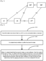
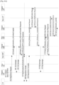
- Fig. 1 illustrates a schematic diagram of system architecture in a 5G communication system.
- network elements in the 5G communication system may be classified into different types of elements, for example, User Equipments (UEs), Access Nodes (ANs), Access Mobility management Functional entities (AMF), Session Management Functional entities (SMF), and User Plane Functional entities (UPF) etc., according to tasks undertaken.
- UEs User Equipments
- ANs Access Nodes
- AMF Access Mobility management Functional entities
- SMF Session Management Functional entities
- UPF User Plane Functional entities
- a UPF After a UE enters a CM-IDLE state, when a UPF receives downlink data for the UE, the UPF transmits a Downlink Data Notification (DDN) to an SMF, and expects the UE to reconstruct a user plane.
- DDN Downlink Data Notification
- the SMF then notifies the AMF, and the AMF initiates a paging procedure to an AN.
- the UE After the UE receives paging signaling, the UE returns to a CM-CONNECTED state, and restores a user plane function with the UPF to receive data.
- DDN Downlink Data Notification
- the SMF may instruct the UPF to temporarily buffer data on the UPF (without expecting the UE to reconstruct the plane) after receiving the DDN and not transmit the DDN to the SMF at the same time.
- the SMF may also determine how long the data is buffered or a number of data packets to be buffered.
- the AN After the UE enters a RRC-INACTIVE state, the AN initiates an RAN paging procedure after receiving the downlink data of the UE. After the UE receives the paging signaling, the UE returns to a RRC-CONNECTED state, and recovers a wireless link with the AN to receive the downlink data.
- the above process may cause the UE which has entered a non-connected state (for example, the CM-IDLE state or the RRC-INACTIVE state) to be frequently woken up through paging signaling (for example, paging or RAN paging) to re-enter the connected state (for example, the CM-CONNECTED state or the RRC-CONNECTED state), thereby resulting in a large power consumption of the UE.
- paging signaling for example, paging or RAN paging
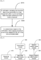
- Fig. 2 illustrates a flowchart of a method performed at a first node for transmitting data according to an embodiment of the present disclosure. As shown in Fig. 2 , the method comprises step S210, in which downlink data to be transmitted to a User Equipment (UE) in a non-connected state is received.
- UE User Equipment
- non-connected state refers to a state in which a connection for signal transmission between the UE and a network device is not established, for example, an CM-IDLE state, a RRC-INACTIVE state, or any other similar states.
- the determination may be made based on a priority of the downlink data.
- determining whether to buffer the downlink data may comprise: determining, based on a priority of the downlink data, whether to buffer the downlink data. Specifically, if the downlink data is data of a high priority, it is determined that the downlink data is to be transmitted immediately, rather than to be buffered, and if the downlink data is not data of a high priority, it is determined that the downlink data is to be buffered.
- the data may be prioritized using any method for dividing data into data of a high priority and data of a low priority in the related art, which will not be described in detail here.
- a network node such as the UPF etc. may determine the priority of the downlink data and add an Information Element (IE) of "Flow Priority" in a GTP-U data packet header of the downlink data.
- the UPF may use the IE to indicate how important the data carried by the data packet is for the UE. Therefore, the AN may decide whether to initiate a RAN Paging procedure immediately according to the IE.
- IE Information Element
- the technical solutions according to the embodiments of the present disclosure are not limited thereto, and it may be determined whether to buffer the downlink data according to any other feasible manner (for example, but not limited to, a buffer capacity, a data transmission scheduling policy, etc.)
- step S230 when it is determined that the downlink data is to be buffered, if the first node is a first type of node, it is determined that a paging procedure is not to be initiated for the UE in the non-connected state, or if the first node is a second type of node, the second node is notified that the downlink data has been buffered, so that the second node determines that the paging procedure is not to be initiated for the UE in the non-connected state.
- the above notification to the second node may be IEs of a "Gateway buffered data indication", an "AN buffered data indication", or any message or information which may implement a similar function, and the present disclosure is not limited by a specific implementation.
- the method shown in Fig. 2 may further comprise: determining, based on occurrence of a predefined event, that the buffered data is to be transmitted to the UE in the non-connected state.
- the predefined event may comprise, but not limited to, at least one of: the UE actively returning to a connected state, occurrence of downlink data to be transmitted immediately (for example, data of a high priority for the UE), timeout of a predefined timer, and an event that a predefined upper limit of the buffered data has been reached.
- the first node may further notify the second node that the downlink data has been buffered.
- a notification to the second node may carry an information element indicating that the data is buffered by the first node.
- notifying the second node that the downlink data has been buffered may comprise: transmitting, to a third node, a message carrying an information element indicating that the data is buffered by the first node, so that the third node notifies the second node that the data is buffered by the first node.
- the first type of node may be an Access Node (AN)
- the second type of node may be an User Plane Functional entity (UPF)
- the second node may be an Access Mobility management Functional entity (AMF)
- the third node may be a Session Management Functional entity (SMF).
- the technical solutions according to the embodiments of the present disclosure are not limited thereto, and the first type of node, the second type of node, the second node, and the third node may also be corresponding nodes which have similar functions in an existing communication system or a future communication system, respectively, and should not be limited to the AN, the UPF, or the AMF.
- the UE actively returning to a connected state may comprise the UE updating its registration area (for example, entering a new registration area).
- the method shown in Fig. 2 may further comprise: assisting in creation of a user plane session between the UE and the updated registration area, so that the buffered data may be transmitted using the created user plane session.
- Fig. 3 illustrates a flowchart of a method performed at a second node for transmitting data according to an embodiment of the present disclosure.
- the method comprises step S310, in which a notification indicating that downlink data to be transmitted to a User Equipment (UE) in a non-connected state has been buffered at a first node is received.
- UE User Equipment
- the above notification to the second node may be IEs of a "Gateway buffered data indication", an "AN buffered data indication", or any message or information which may implement a similar function, and the present disclosure is not limited by a specific implementation.
- step s320 it is determined, based on the notification, that a paging procedure is not to be initiated for the UE in the non-connected state.
- the method shown in Fig. 3 may further comprise: determining, based on occurrence of a predefined event, that the buffered data is to be transmitted to the UE in the non-connected state.
- the predefined event may comprise, but not limited to, at least one of: the UE actively returning to a connected state, occurrence of downlink data to be transmitted immediately (for example, data of a high priority for the UE), timeout of a predefined timer, and an event that a predefined upper limit of the buffered data has been reached.
- the notification is received from the first node via a third node
- the method shown in Fig. 3 may further comprise: receiving, from the third node, a message comprising an information element indicating a forwarding data channel address of the first node.
- the method shown in Fig. 3 may further comprise: transmitting, to another second node, a message comprising an information element indicating that the data is buffered by the first node and/or the message comprising the information element indicating the forwarding data channel address of the first node, so that the other second node forwards the message to another third node.
- the other second node is a second node to which the UE connects when the UE updates its registration area, and the message which is transmitted to the other second node and comprises the information element indicating that the data is buffered by the first node is used to trigger the other second node to initiate a Packet Data Unit (PDU) session establishment procedure.
- PDU Packet Data Unit
- the first node may be an User Plane Functional entity (UPF)
- the second node and the other second node may be Access Mobility management Functional entities (AMF)
- the third node and the other third node may be Session Management Functional entities (SMF).
- UPF User Plane Functional entity
- AMF Access Mobility management Functional entities
- SMF Session Management Functional entities
- the technical solutions according to the embodiments of the present disclosure are not limited thereto, and the first node, the second node, and the third node may also be corresponding nodes which have similar functions in an existing communication system or a future communication system, respectively, and should not be limited to the UPF, the AMF, or the SMF.
- the UE actively returning to a connected state may comprise the UE updating its registration area (for example, entering a new registration area).
- the method shown in Fig. 3 may further comprise: assisting in creation of a user plane session between the UE and the updated registration area, so that the buffered data may be transmitted to the UE using the created user plane session.
- Fig. 4 illustrates a schematic block diagram of a first node for transmitting data according to an embodiment of the present disclosure.
- the first node may comprise a receiving module 410, a data buffer determination module 420 and a paging initiation determination module 430.
- the receiving module 410 is configured to receive downlink data to be transmitted to a User Equipment (UE) in a non-connected state.
- UE User Equipment
- non-connected state refers to a state in which a connection for signal transmission between the UE and a network device is not established, for example, an CM-IDLE state, a RRC-INACTIVE state, or any other similar states.
- the data buffer determination module 420 is configured to determine whether to buffer the downlink data.
- the determination may be made based on a priority of the downlink data.
- determining whether to buffer the downlink data may comprise: determining, based on a priority of the downlink data, whether to buffer the downlink data. Specifically, if the downlink data is data of a high priority, it is determined that the downlink data is to be transmitted immediately, rather than to be buffered, and if the downlink data is not data of a high priority, it is determined that the downlink data is to be buffered.
- the data may be prioritized using any method for dividing data into data of a high priority and data of a low priority in the related art, which will not be described in detail here.
- a network node such as the UPF etc. may determine the priority of the downlink data and may add an IE of "Flow Priority" in a GTP-U data packet header of the downlink data.
- the UPF may use the IE to indicate how important the data carried by the data packet is for the UE. Therefore, the AN may decide whether to initiate a RAN Paging procedure immediately according to the IE.
- the technical solutions according to the embodiments of the present disclosure are not limited thereto, and it may be determined whether to buffer the downlink data according to any other feasible manner (for example, but not limited to, a buffer capacity, a data transmission scheduling policy, etc.)
- the paging initiation determination module 430 is configured to, when it is determined that the downlink data is to be buffered, if the first node is a first type of node, determine that a paging procedure is not to be initiated for the UE in the non-connected state, or if the first node is a second type of node, notify the second node that the downlink data has been buffered, so that the second node determines that the paging procedure is not to be initiated for the UE in the non-connected state.
- the above notification to the second node may be IEs of a "Gateway buffered data indication", an "AN buffered data indication", or any message or information which may implement a similar function, and the present disclosure is not limited by a specific implementation.
- the paging initiation determination module 430 may further be configured to: determine, based on occurrence of a predefined event, that the buffered data is to be transmitted to the UE in the non-connected state.
- the predefined event may comprise, but not limited to, at least one of: the UE actively returning to a connected state, occurrence of downlink data to be transmitted immediately (for example, data of a high priority for the UE), timeout of a predefined timer, and an event that a predefined upper limit of the buffered data has been reached.
- the second node may further be notified through a transmission module 450 that the downlink data has been buffered.
- a notification to the second node may carry an information element indicating that the data is buffered by the first node.
- the transmission module 450 may be configured to transmit, to a third node, a message carrying an information element indicating that the data is buffered by the first node, so that the third node notifies the second node that the data is buffered by the first node.
- the first type of node may be an Access Node (AN)
- the second type of node may be an User Plane Functional entity (UPF)
- the second node may be an Access Mobility management Functional entity (AMF)
- the third node may be a Session Management Functional entity (SMF).
- the technical solutions according to the embodiments of the present disclosure are not limited thereto, and the first type of node, the second type of node, the second node, and the third node may also be corresponding nodes which have similar functions in an existing communication system or a future communication system, respectively, and should not be limited to the AN, the UPF, or the AMF.
- the UE actively returning to a connected state may comprise the UE updating its registration area (for example, entering a new registration area).
- the device shown in Fig. 4 may further comprise a session creation assist module 440 configured to assist in creation of a user plane session between the UE and the updated registration area, so that the buffered data may be transmitted using the created user plane session.
- the first node illustrated in Fig. 4 may correspond to the first node 1000 illustrated in Fig. 10 .
- the transceiver 1020 of the first node 1000 may comprise the receiving module 410 and the transmission module 450, or perform the operations performed by the receiving module 410 and the transmission module 450.
- the processor 1010 of the first node 1000 may comprise the data buffer determination module 420, the paging initiation determination module 430, and the session creation assist module 440, or perform the operations performed by the data buffer determination module 420, the paging initiation determination module 430, and the session creation assist module 440.
- Fig. 5 illustrates a schematic block diagram of a second node for transmitting data according to an embodiment of the present disclosure.
- the second node comprises a notification receiving module 510.
- the notification receiving module 510 is configured to receive a notification indicating that downlink data to be transmitted to a User Equipment (UE) in a non-connected state has been buffered at a first node.
- UE User Equipment
- the above notification to the second node may be IEs of a "Gateway buffered data indication", an "AN buffered data indication", or any message or information which may implement a similar function, and the present disclosure is not limited by a specific implementation.
- the second node may comprise a paging initiation determination module 520.
- the paging initiation determination module 520 is configured to determine, based on the notification, that a paging procedure is not to be initiated for the UE in the non-connected state.
- the paging initiation determination module 520 may further be configured to determine, based on occurrence of a predefined event, that the buffered data is to be transmitted to the UE in the non-connected state.
- the predefined event may comprise, but not limited to, at least one of: the UE actively returning to a connected state, occurrence of downlink data to be transmitted immediately (for example, data of a high priority for the UE), timeout of a predefined timer, and an event that a predefined upper limit of the buffered data has been reached.
- the notification is received by the notification receiving module 510 from the first node via a third node, and the notification receiving module 510 may further be configured to receive, from the third node, a message comprising an information element indicating a forwarding data channel address of the first node.
- the device shown in Fig. 5 may further comprise a transmission module 540, configured to transmit, to another second node, a message comprising an information element indicating that the data is buffered by the first node and/or the message comprising the information element indicating the forwarding data channel address of the first node, so that the other second node forwards the message to another third node.
- a transmission module 540 configured to transmit, to another second node, a message comprising an information element indicating that the data is buffered by the first node and/or the message comprising the information element indicating the forwarding data channel address of the first node, so that the other second node forwards the message to another third node.
- the other second node is a second node to which the UE connects when the UE updates its registration area, and the message which is transmitted to the other second node and comprises the information element indicating that the data is buffered by the first node is used to trigger the other second node to initiate a Packet Data Unit (PDU) session establishment procedure.
- PDU Packet Data Unit
- the first node may be an User Plane Functional entity (UPF)
- the second node and the other second node may be Access Mobility management Functional entities (AMF)
- the third node and the other third node may be Session Management Functional entities (SMF).
- UPF User Plane Functional entity
- AMF Access Mobility management Functional entities
- SMF Session Management Functional entities
- the technical solutions according to the embodiments of the present disclosure are not limited thereto, and the first node, the second node, and the third node may also be corresponding nodes which have similar functions in an existing communication system or a future communication system, respectively, and should not be limited to the UPF, the AMF, or the SMF.
- the UE actively returning to a connected state may comprise the UE updating its registration area (for example, entering a new registration area).
- the device shown in Fig. 5 may further comprise a session creation assist module 530, configured to assist in creation of a user plane session between the UE and the updated registration area, so that the buffered data may be transmitted using the created user plane session.
- the second node illustrated in Fig. 5 may correspond to the second node 1100 illustrated in Fig. 11 .
- the transceiver 1120 of the second node 1100 may comprise the notification receiving module 510 and the transmission module 540, or perform the operations performed by the notification receiving module 510 and the transmission module 540.
- the processor 1110 of the second node 1100 may comprise the paging initiation determination module 520 and the session creation assist module 530, or perform the operations performed by the paging initiation determination module 520 and the session creation assist module 530.
- the UPF may not require an indication of an SMF, and may decide whether to temporarily buffer the data on the UPF by itself (in a case where the UE is not expected to re-create a plane). However, the UPF still needs to transmit a DDN to the SMF to notify the SMF that there is data buffered on the UPF. The SMF also needs to notify the AMF that there is data buffered on the UPF. At that time, the AMF may not start a Paging procedure. In this case, the downlink data is buffered on the UPF while the UE is still maintained in the CM-IDLE state.
- the AN may decide to buffer the data in the AN without initiating a RAN Paging procedure. In this case, the downlink data is buffered in the AN while the UE is still maintained in the RRC-INACTIVE state.
- the UE is maintained in the non-connected state (for example, the CM-IDLE state or the RRC-INACTIVE state) in the above manner, which reduces a number of times the UE is woken up through paging signaling after the UE enters the CM-IDLE state to re-enter a CM-CONNECTED state, and/or reduces a number of times the UE is woken up by a RAN Paging procedure after the UE enters the RRC-INACTIVE state to re-enter a RRC-CONNECTED state, thereby achieving energy saving at the UE.
- the non-connected state for example, the CM-IDLE state or the RRC-INACTIVE state
- the method according to the embodiments of the present application may comprise one or more of the following operations.
- the above operations are just specific examples provided for explaining the technical solutions according to the embodiments of the present disclosure, and should not be construed as limiting the protection scope of the present disclosure.
- the above operations 3, 5, 10, etc. may not be included.
- the above operations 7, 11, etc. may also be omitted.
- the operations 1-6 and the operations 7-11 may be performed in any relative order according to specific conditions.
- the buffered data may be transmitted to the UE when some predefined events occur. As an example of the UE actively returning to the connected state, the UE may enter a new registration area and update the registration area.
- a specific process of transmitting the buffered data to the UE will be described below by taking the case where the UE updates the registration area as an example. It is to be illustrated that the following embodiments are merely illustrative of specific examples of the technical solutions according to the present disclosure, and should not be construed as limiting the protection scope of the present disclosure.
- a case where after the UPF receives the downlink data but the AMF decides not to start the paging procedure when the UE is in the CM-IDLE state, the UE enters a new registration area is described.
- the UE is allocated to a new AMF, a new SMF, and a new UPF, and the original SMF may communicate with the new SMF.
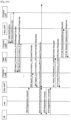
- Figs. 6A and 6B illustrate schematic flowcharts of one specific implementation of a method for transmitting data according to an embodiment of the present disclosure in this case. As shown in Figs. 6A and 6B , the specific implementation comprises the following steps.
- step 601 after the UE enters the CM-IDLE state, the original UPF receives downlink data.
- the original UPF decides to buffer the downlink data.
- the original UPF transmits a Data Notification to the original SMF, wherein the message carries a relevant session ID and a gateway buffered data indication, but is not limited to these contents.
- step 602 the original SMF transmits a Data Notification Ack to the original UPF.
- the original SMF transmits a Namf_Communication_N1N2MessageTransfer to the original AMF.
- the message should carry the relevant session ID and the gateway buffered data indication, but is not limited to these contents.
- step 604 the original AMF transmits a Namf_Communication_N1N2MessageTransfer Response to the original SMF.
- step 605 the UE moves to a new registration area in the CM-IDLE state.
- the UE transmits a registration request to the new AMF through the AN.
- step 606 the new AMF transmits a Namf_Communication_UEContextTransfer to the original AMF.
- the message should carry the above registration request, but is not limited to these contents.
- the original AMF transmits a Namf_Communication_UEContextTransfer Response to the new AMF.
- the message should carry a mobility management context and SMF information, but is not limited to these contents.
- the SMF information should carry the relevant session ID and the gateway buffered data indication, but is not limited to these contents.
- step 608 the UE completes identification, authentication, security, UDM-related procedures, PCF-related procedures etc. It can be illustrated here that an arrow on the right of step 608 does not point to a particular network entity. Such an indication manner herein means that there may also be network entities which are not shown in the figure and are involved in this step.
- step 609 the new AMF transmits a Registration Accept to the UE through the AN.
- step 610 the UE transmits a Registration Complete to the new AMF through the AN.
- the new AMF transmits a Nsmf_PDUSession_CreateSMContext Request to the new SMF.
- the creation request is transmitted based on, for example, the gateway buffered data indication received by the new AMF from the original AMF, and thereby a PDU session establishment procedure is initiated.
- step 612 the new SMF transmits a Nsmf_PDUSession_CreateSMContext Response to the new AMF.
- step 613 the new SMF transmits a N4 Session Establishment Request to the new UPF.
- the new UPF transmits a N4 Session Establishment Response to the new SMF.
- the message should carry CN channel information, but is not limited to these contents.
- the CN channel information is allocated by the new UPF.
- the new SMF transmits a Nsmf_PDUSession_Update to the original SMF.
- the message should carry the above CN channel information, but is not limited to these contents.
- the original SMF transmits a N4 Session Modification Request to the original UPF.
- the message should carry the above CN channel information, but is not limited to these contents.
- the original UPF transmits a N4 Session Modification Response to the original SMF.
- the message should carry the CN channel information, but is not limited to these contents.
- the CN channel information is allocated by the original UPF.
- the new SMF transmits the N4 Session Modification Request to the new UPF.
- the message should carry the CN channel information allocated by the original UPF, but is not limited to these contents.
- step 620 the new UPF transmits the N4 Session Modification Response to the new SMF.
- step 621 the new SMF transmits Namf_Communication_N1N2MessageTransfer to the new AMF.
- the new AMF transmits an Namf_Communication_N1N2MessageTransfer Response to the new SMF.
- step 623 the new AMF transmits a N2 PDU Session Resource Setup Request to the AN.
- step 624 the UE completes an RRC connection reconfiguration procedure with the AN.
- step 625 the AN transmits a N2 PDU Session Resource Setup Response to the new AMF.
- step 626 the new AMF transmits a Nsmf_PDUSession_ UpdateSMContext Request to the new SMF.
- step 627 the new SMF transmits the N4 Session Modification Request to the new UPF.
- step 628 the new UPF transmits the N4 Session Modification Response to the new SMF.
- the new SMF transmits a Nsmf_PDUSession_ UpdateSMContext Response to the new AMF.
- the downlink data buffered by the original UPF may be transmitted to the UE through the new UPF and the AN.
- a case where after the UPF receives the downlink data but the AMF decides not to start the paging procedure when the UE is in the CM-IDLE state, the UE enters a new registration area is described.
- the UE is allocated to a new AMF, a new SMF, and a new UPF, and the original SMF cannot communicate with the new SMF.
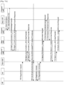
- Figs. 7A and 7B illustrate schematic flowcharts of another specific implementation of a method for transmitting data according to an embodiment of the present disclosure in this case. As shown in Figs. 7A and 7B , the specific implementation comprises the following steps.
- step 701 after the UE enters the CM-IDLE state, the original UPF receives downlink data.
- the original UPF decides to buffer the downlink data.
- the original UPF transmits a Data Notification to the original SMF, wherein the message should carry a relevant session ID and a gateway buffered data indication, but is not limited to these contents.
- step 702 the original SMF transmits a Data Notification Ack to the original UPF.
- the original SMF transmits a Namf_Communication_N1N2MessageTransfer to the original AMF.
- the message should carry the relevant session ID and the gateway buffered data indication, but is not limited to these contents.
- step 704 the original AMF transmits a Namf_Communication_N1N2MessageTransfer Response to the original SMF.
- step 705 the UE moves to a new registration area in the CM-IDLE state.
- the UE transmits a registration request to the new AMF through the AN.
- step 706 the new AMF transmits A Namf_Communication_UEContextTransfer to the original AMF.
- the message should carry the above registration request, but is not limited to these contents.
- the original AMF transmits a Namf_Communication_UEContextTransfer Response to the new AMF.
- the message should carry a mobility management context and SMF information, but is not limited to these contents.
- the SMF information should carry the relevant session ID and the gateway buffered data indication, but is not limited to these contents.
- step 708 the UE completes identification, authentication, security, UDM-related procedures, PCF-related procedures etc.
- step 709 the new AMF transmits a Registration Accept to the UE through the AN.
- step 710 the UE transmits a Registration Complete to the new AMF through the AN.
- step 711 the new AMF transmits a Nsmf_PDUSession_CreateSMContext Request to the new SMF.
- step 712 the new SMF transmits a N4 Session Establishment Request to the new UPF.
- the new UPF transmits a N4 Session Establishment Response to the new SMF.
- the message should carry CN channel information, but is not limited to these contents.
- the CN channel information is allocated by the new UPF.
- the new SMF transmits a Nsmf_PDUSession_CreateSMContext Response to the new AMF.
- the message should carry the CN channel information allocated by the new UPF, but is not limited to these contents.
- the new AMF transmits the a Namf_Communication_UEContextTransfer to the original AMF.
- the message should carry the CN channel information allocated by the new UPF, but is not limited to these contents.
- the original AMF transmits a Nsmf_PDUSession_ UpdateSMContext Request to the original SMF.
- the message should carry the CN channel information allocated by the new UPF, but is not limited to these contents.
- the original SMF transmits a N4 Session Modification Request to the original UPF.
- the message should carry the CN channel information allocated by the new UPF, but is not limited to these contents.
- the original UPF transmits a N4 Session Modification Response to the original SMF.
- the message should carry the CN channel information, but is not limited to these contents.
- the CN channel information is allocated by the original UPF.
- the original SMF transmits a Nsmf_PDUSession_ UpdateSMContext Response to the original AMF.
- the message should carry the CN channel information allocated by the original UPF, but is not limited to these contents.
- the original AMF transmits the Namf_Communication_UEContextTransfer Response to the new AMF.
- the message should carry the CN channel information allocated by the original UPF, but is not limited to these contents.
- the new AMF transmits the Nsmf_PDUSession_ UpdateSMContext Request to the new SMF.
- the message should carry CN channel information allocated by the original UPF, but is not limited to these contents.
- the new SMF transmits the N4 Session Modification Request to the new UPF.
- the message should carry the CN channel information allocated by the original UPF, but is not limited to these contents.
- step 723 the new UPF transmits the N4 Session Modification Response to the new SMF.
- step 724 the new SMF transmits the Nsmf_PDUSession_ UpdateSMContext Response to the new AMF.
- step 725 the new SMF transmits a Namf_Communication_N1N2MessageTransfer to the new AMF.
- step 726 the new AMF transmits a Namf_Communication_N1N2MessageTransfer Response to the new SMF.
- step 727 the new AMF transmits a N2 PDU Session Resource Setup Request to the AN.
- step 728 the UE completes an RRC connection reconfiguration procedure with the AN.
- step 729 the AN transmits a N2 PDU Session Resource Setup Response to the new AMF.
- step 730 the new AMF transmits the Nsmf_PDUSession_ UpdateSMContext Request to the new SMF.
- step 731 the new SMF transmits the N4 Session Modification Request to the new UPF.
- step 732 the new UPF transmits the N4 Session Modification Response to the new SMF.
- the new SMF transmits the Nsmf_PDUSession_ UpdateSMContext Response to the new AMF.
- the downlink data buffered by the original UPF may be transmitted to the UE through the new UPF and the AN.
- a case where after the AN receives the downlink data but the AN decides not to start the RAN paging procedure when the UE is in the RRC-INACTIVE state, the UE enters a new registration area is described.
- the UE is connected to a new AN, and is allocated to a new AMF, a new SMF, and a new UPF.
- Figs. 8A and 8B illustrate schematic flowcharts of another specific implementation of a method for transmitting data according to an embodiment of the present disclosure in this case. As shown in Figs. 8A and 8B , the specific implementation comprises the following steps.
- step 801 the UE is in the RRC-INACTIVE state, the AN receives downlink data, but the AN decides not to start the RAN Paging procedure.
- the AN buffers the downlink data.
- step 802 the UE enters a new registration area in the RRC-INACTIVE state.
- the UE transmits a registration request to the new AMF through the AN.
- step 803 the new AMF transmits a Namf_Communication_UEContextTransfer to the original AMF.
- the message should carry the above registration request, but is not limited to these contents.
- the original AMF transmits a N2 message to the original AN.
- the N2 message may be a UE State Transition Notification Request.
- the original AN transmits a N2 message to the original AMF.
- the N2 message may be a UE notification.
- the message should carry an AN buffered data indication, but is not limited to these contents.
- the original AMF transmits a Namf_Communication_UEContextTransfer Response to the new AMF.
- the message should carry a mobility management context and SMF information, but is not limited to these contents.
- the SMF information should carry the relevant session ID and the AN buffered data indication, but is not limited to these contents.
- step 807 the UE completes identification, authentication, security, UDM-related procedures, PCF-related procedures etc.
- step 808 the new AMF transmits a Registration Accept to the UE through the AN.
- step 809 the UE transmits a Registration Complete to the new AMF through the AN.
- step 810 after step 806, the original AMF may transmit a Nsmf_PDUSession_ UpdateSMContext Request to the original SMF.
- step 811 the original SMF transmits a N4 Session Modification Request to the original UPF.
- the original UPF transmits a N4 Session Modification Response to the original SMF.
- the message should carry N3 interface orientated data channel information allocated by the original UPF, but is not limited to these contents.
- the original SMF transmits a Nsmf_PDUSession_ UpdateSMContext Response to the original AMF.
- the message should carry the N3 interface orientated data channel information allocated by the original UPF, but is not limited to these contents.
- the original AMF transmits a N2 message to the original AN.
- the message may be a PDU session resource modification request on the N2 interface.
- the message should carry the N3 interface orientated data channel information allocated by the original UPF, but is not limited to these contents.
- the original AN transmits a N2 message to the original AMF.
- the message may be a PDU session resource modification response on the N2 interface.
- the original AN may transmit the buffered downlink data to the original UPF.
- step 816 after step 806, the new AMF transmits a Nsmf_PDUSession_CreateSMContext Request to the new SMF.
- step 817 the new SMF transmits a Nsmf_PDUSession_CreateSMContext Response to the new AMF.
- step 818 the new SMF transmits a N4 Session Establishment Request to the new UPF.
- the new UPF transmits a N4 Session Establishment Response to the new SMF.
- the message should carry the N3 interface orientated data channel information and CN channel information, but is not limited to these contents.
- the N3 interface orientated data channel information and the CN channel information are allocated by the new UPF.
- the new SMF transmits a Nsmf_PDUSession_Update to the original SMF.
- the message should carry the CN channel information allocated by the new UPF, but is not limited to these contents.
- the original SMF transmits the N4 Session Modification Request to the original UPF.
- the message should carry the CN channel information allocated by the new UPF, but is not limited to these contents.
- the original UPF transmits the N4 Session Modification Response to the original SMF.
- the message should carry the CN channel information, but is not limited to these contents.
- the CN channel information is allocated by the original UPF.
- the original SMF transmits a Nsmf_PDUSession_Update Response to the new SMF.
- the message should carry the CN channel information allocated by the original UPF, but is not limited to these contents.
- the new SMF transmits the N4 Session Modification Request to the new UPF.
- the message should carry the CN channel information allocated by the original UPF, but is not limited to these contents.
- step 825 the new UPF transmits the N4 Session Modification Response to the new SMF.
- the original UPF may forward the buffered data to the new UPF.
- the new SMF transmits a Namf_Communication _N1N2MessageTransfer to the new AMF.
- the message should carry the N3 interface orientated data channel information allocated by the new UPF, but is not limited to these contents.
- step 827 the new AMF transmits a Namf_Communication_N1N2MessageTransfer Response to the new SMF.
- the new AMF transmits a N2 PDU Session Resource Setup Request to the new AN.
- the message should carry the N3 interface orientated data channel information allocated by the new UPF, but is not limited to these contents.
- step 829 the UE completes an RRC connection reconfiguration procedure with the AN.
- the new AN transmits a N2 PDU Session Resource Setup Response to the new AMF.
- the message should carry the N3 interface orientated data channel information allocated by the new AN, but is not limited to these contents.
- the new AMF may transmit a Nsmf_PDUSession_ UpdateSMContext Request to the new SMF.
- the message should carry the N3 interface orientated data channel information allocated by the new AN, but is not limited to these contents.
- the new SMF transmits the N4 Session Modification Request to the new UPF.
- the message should carry the N3 interface orientated data channel information allocated by the new AN, but is not limited to these contents.
- the new UPF transmits the N4 Session Modification Response to the new SMF.
- the data buffered by the new UPF may be transmitted to the UE through the new AN.
- step 834 the new SMF transmits the Nsmf_PDUSession_ UpdateSMContext Response to the new AMF.
- the original AN may transmit a N2 UE Context Release Request to the original AMF.
- the predefined event may be completion of forwarding of the data buffered on the original AN by the original AN, or timeout of a predefined timer.
- the original AMF may transmit a N2 UE Context Release Command to the original AN.
- the original AN may transmit a N2 UE Context Release Complete to the original AMF.
- the original AMF may transmit a Nsmf_PDUSession_ UpdateSMContext Request to the original SMF.
- step 839 the original SMF transmits the N4 Session Modification Request to the original UPF.
- step 840 the original UPF transmits the N4 Session Modification Response to the original SMF.
- step 841 the original SMF transmits the Nsmf_PDUSession_ UpdateSMContext Response to the original AMF.
- Fig. 9 schematically illustrates a block diagram of a device 900 according to an embodiment of the present disclosure.
- the device 900 comprises a processor 910, for example, a Digital Signal Processor (DSP).
- the processor 910 may be a single apparatus or multiple apparatuses for performing different actions according to the embodiments of the present disclosure.
- the device 900 may further comprise an Input/Output (I/O) apparatus 930 configured to receive signals from other entities or transmit signals to other entities.
- I/O Input/Output
- the device 900 comprises a memory 920 which may be in a form of non-volatile or volatile memory, for example, an Electrically Erasable Programmable Read Only Memory (EEPROM), a flash memory, etc.
- the memory 920 has computer readable instructions stored thereon, which when executed by the processor 910, cause the processor to perform the method according to the embodiments of the present disclosure.
- the device illustrated in Fig. 9 may correspond to the device 1200 illustrated in Fig. 12 .
- the transceiver 1220 of the device 1200 may comprise the Input/Output (I/O) apparatus 930 or perform the operations performed by the Input/Output (I/O) apparatus 930.
- the processor 1210 of the device 1200 may comprise the processor 910 or perform the operations performed by the processor 910.
- the memory 1230 of the device 1200 may comprise the memory 920 or perform the operations performed by the memory 920.
- Fig. 10 schematically illustrates a block diagram of a first node 1000 according to an embodiment of the present disclosure.
- the first nodes described above may correspond to the first node 1000.
- the first nodex illustrated in Fig. 4 may correspond to the first node 1000.
- the first node 1000 may include a processor 1010, a transceiver 1020 and a memory 1030. However, all of the illustrated components are not essential. The first node 1000 may be implemented by more or less components than those illustrated in Fig. 10 . In addition, the processor 1010 and the transceiver 1020 and the memory 1030 may be implemented as a single chip according to another embodiment.
- the processor 1010 may include one or more processors or other processing devices that control the proposed function, process, and/or method. Operation of the first node 1000 may be implemented by the processor 1010.
- the processor 1010 may detect a PDCCH on a configured control resource set.
- the processor 1010 determines a method for dividing CBs and a method for rate matching of a PDSCH according to the PDCCH.
- the processor 1010 may control the transceiver 1020 to receive the PDSCH according to the PDCCH.
- the processor 1010 may generate HARQ-ACK information according to the PDSCH.
- the processor 1010 may control the transceiver 1020 to transmit the HARQ-ACK information.
- the transceiver 1020 may include a RF transmitter for up-converting and amplifying a transmitted signal, and a RF receiver for down-converting a frequency of a received signal.
- the transceiver 1020 may be implemented by more or less components than those illustrated in components.
- the transceiver 1020 may be connected to the processor 1010 and transmit and/or receive a signal.
- the signal may include control information and data.
- the transceiver 1020 may receive the signal through a wireless channel and output the signal to the processor 1010.
- the transceiver 1020 may transmit a signal output from the processor 1010 through the wireless channel.
- the memory 1030 may store the control information or the data included in a signal obtained by the first node 1000.
- the memory 1030 may be connected to the processor 1010 and store at least one instruction or a protocol or a parameter for the proposed function, process, and/or method.
- the memory 1030 may include read-only memory (ROM) and/or random access memory (RAM) and/or hard disk and/or CD-ROM and/or DVD and/or other storage devices.
- Fig. 11 schematically illustrates a block diagram of a second node 1100 according to an embodiment of the present disclosure.
- the second nodes described above may correspond to the second node 1100.
- the second node illustrated in Fig. 5 may correspond to the second node 1100.
- the second node 1100 may include a processor 1110, a transceiver 1120 and a memory 1130. However, all of the illustrated components are not essential. The second node 1100 may be implemented by more or less components than those illustrated in Fig. 11 . In addition, the processor 1110 and the transceiver 1120 and the memory 1130 may be implemented as a single chip according to another embodiment.
- the processor 1110 may include one or more processors or other processing devices that control the proposed function, process, and/or method. Operation of the second node 1100 may be implemented by the processor 1110.
- the processor 1110 may detect a PDCCH on a configured control resource set.
- the processor 1110 determines a method for dividing CBs and a method for rate matching of a PDSCH according to the PDCCH.
- the processor 1110 may control the transceiver 1120 to receive the PDSCH according to the PDCCH.
- the processor 1110 may generate HARQ-ACK information according to the PDSCH.
- the processor 1110 may control the transceiver 1120 to transmit the HARQ-ACK information.
- the transceiver 1120 may include a RF transmitter for up-converting and amplifying a transmitted signal, and a RF receiver for down-converting a frequency of a received signal.
- the transceiver 1120 may be implemented by more or less components than those illustrated in components.
- the transceiver 1120 may be connected to the processor 1110 and transmit and/or receive a signal.
- the signal may include control information and data.
- the transceiver 1120 may receive the signal through a wireless channel and output the signal to the processor 1110.
- the transceiver 1120 may transmit a signal output from the processor 1110 through the wireless channel.
- the memory 1130 may store the control information or the data included in a signal obtained by the second node 1100.
- the memory 1130 may be connected to the processor 1110 and store at least one instruction or a protocol or a parameter for the proposed function, process, and/or method.
- the memory 1130 may include read-only memory (ROM) and/or random access memory (RAM) and/or hard disk and/or CD-ROM and/or DVD and/or other storage devices.
- Fig. 12 schematically illustrates a block diagram of a device 1200 according to an embodiment of the present disclosure.
- the devices or UEs described above may correspond to the device 1200.
- the device illustrated in Fig. 9 may correspond to the device 1200.
- the device 1200 may include a processor 1210, a transceiver 1220 and a memory 1230. However, all of the illustrated components are not essential. The device 1200 may be implemented by more or less components than those illustrated in Fig. 12 . In addition, the processor 1210 and the transceiver 1220 and the memory 1230 may be implemented as a single chip according to another embodiment.
- the processor 1210 may include one or more processors or other processing devices that control the proposed function, process, and/or method. Operation of the device 1200 may be implemented by the processor 1210.
- the processor 1210 may detect a PDCCH on a configured control resource set.
- the processor 1210 determines a method for dividing CBs and a method for rate matching of a PDSCH according to the PDCCH.
- the processor 1210 may control the transceiver 1220 to receive the PDSCH according to the PDCCH.
- the processor 1210 may generate HARQ-ACK information according to the PDSCH.
- the processor 1210 may control the transceiver 1220 to transmit the HARQ-ACK information.
- the transceiver 1220 may include a RF transmitter for up-converting and amplifying a transmitted signal, and a RF receiver for down-converting a frequency of a received signal.
- the transceiver 1220 may be implemented by more or less components than those illustrated in components.
- the transceiver 1220 may be connected to the processor 1210 and transmit and/or receive a signal.
- the signal may include control information and data.
- the transceiver 1220 may receive the signal through a wireless channel and output the signal to the processor 1210.
- the transceiver 1220 may transmit a signal output from the processor 1210 through the wireless channel.
- the memory 1230 may store the control information or the data included in a signal obtained by the device 1200.
- the memory 1230 may be connected to the processor 1210 and store at least one instruction or a protocol or a parameter for the proposed function, process, and/or method.
- the memory 1230 may include read-only memory (ROM) and/or random access memory (RAM) and/or hard disk and/or CD-ROM and/or DVD and/or other storage devices.
- ROM read-only memory
- RAM random access memory
- CD-ROM and/or DVD and/or other storage devices e.g., CD-ROM and/or DVD and/or other storage devices.
- DSP Digital Signal Processing
- ASIC Application-Specific Integrated Circuit
- FPGA Field Programmable Gate Array
- CPLD Programmable Logic Device
- base station refers to a mobile communication data and control switching center having a large transmission power and a relatively large coverage area, which has functions such as resource allocation scheduling, data reception and transmission, etc.
- User Equipment refers to a user mobile terminal, for example, a terminal device which comprises a mobile phone, a notebook, etc., and may communicate wirelessly with a base station or a micro-base station.
- the embodiments of the present disclosure disclosed here may be implemented on a computer program product.
- the computer program product is a product having a computer readable medium encoded with a computer program logic which, when executed on a computing device, provides related operations to implement the technical solutions of the present disclosure.
- the computer program logic When executed on at least one processor of a computing system, the computer program logic causes the processor to perform the operations (methods) described in the embodiments of the present disclosure.
- Such an arrangement according to the present disclosure is typically provided as software, codes and/or other data structures, disposed or encoded on a computer readable medium such as an optical medium (for example, CD-ROM), a floppy disk, or a hard disk etc., firmware or other media for micro-codes on one or more ROM or RAM or PROM chips, or downloadable software images, shared databases, etc. in one or more modules.
- a computer readable medium such as an optical medium (for example, CD-ROM), a floppy disk, or a hard disk etc., firmware or other media for micro-codes on one or more ROM or RAM or PROM chips, or downloadable software images, shared databases, etc. in one or more modules.
- the software or firmware or such a configuration may be installed on the computing device, so that one or more processors in the computing device perform the technical solutions described in the embodiments of the present disclosure.
Landscapes
- Engineering & Computer Science (AREA)
- Computer Networks & Wireless Communication (AREA)
- Signal Processing (AREA)
- Computer Security & Cryptography (AREA)
- Databases & Information Systems (AREA)
- Health & Medical Sciences (AREA)
- Computing Systems (AREA)
- General Health & Medical Sciences (AREA)
- Medical Informatics (AREA)
- Mobile Radio Communication Systems (AREA)
Applications Claiming Priority (3)
| Application Number | Priority Date | Filing Date | Title |
|---|---|---|---|
| CN201810504370.7A CN110536378A (zh) | 2018-05-23 | 2018-05-23 | 一种用于发送数据的方法、设备和存储介质 |
| EP19807633.3A EP3815422B1 (de) | 2018-05-23 | 2019-05-23 | Verfahren und vorrichtungen zur übertragung von daten und speichermedium dafür |
| PCT/KR2019/006225 WO2019225996A1 (en) | 2018-05-23 | 2019-05-23 | Method and device for transmitting data and storage medium thereof |
Related Parent Applications (1)
| Application Number | Title | Priority Date | Filing Date |
|---|---|---|---|
| EP19807633.3A Division EP3815422B1 (de) | 2018-05-23 | 2019-05-23 | Verfahren und vorrichtungen zur übertragung von daten und speichermedium dafür |
Publications (2)
| Publication Number | Publication Date |
|---|---|
| EP4554291A2 true EP4554291A2 (de) | 2025-05-14 |
| EP4554291A3 EP4554291A3 (de) | 2025-07-30 |
Family
ID=68616128
Family Applications (2)
| Application Number | Title | Priority Date | Filing Date |
|---|---|---|---|
| EP25167762.1A Pending EP4554291A3 (de) | 2018-05-23 | 2019-05-23 | Verfahren und vorrichtungen zur datenübertragung und speichermedium dafür |
| EP19807633.3A Active EP3815422B1 (de) | 2018-05-23 | 2019-05-23 | Verfahren und vorrichtungen zur übertragung von daten und speichermedium dafür |
Family Applications After (1)
| Application Number | Title | Priority Date | Filing Date |
|---|---|---|---|
| EP19807633.3A Active EP3815422B1 (de) | 2018-05-23 | 2019-05-23 | Verfahren und vorrichtungen zur übertragung von daten und speichermedium dafür |
Country Status (4)
| Country | Link |
|---|---|
| US (1) | US11310759B2 (de) |
| EP (2) | EP4554291A3 (de) |
| CN (1) | CN110536378A (de) |
| WO (1) | WO2019225996A1 (de) |
Families Citing this family (4)
| Publication number | Priority date | Publication date | Assignee | Title |
|---|---|---|---|---|
| CN111615188B (zh) * | 2019-02-22 | 2021-10-01 | 华为技术有限公司 | 数据传输方法、装置及计算机存储介质 |
| WO2021040724A1 (en) * | 2019-08-29 | 2021-03-04 | Nokia Technologies Oy | Passive mode transition for user equipment based on control plane monitoring |
| CN112822717B (zh) * | 2020-12-31 | 2023-04-28 | 联想未来通信科技(重庆)有限公司 | 一种动态控制报文缓冲的方法、装置及系统 |
| WO2024111054A1 (ja) * | 2022-11-22 | 2024-05-30 | 株式会社Nttドコモ | ネットワークノード及び通信方法 |
Family Cites Families (6)
| Publication number | Priority date | Publication date | Assignee | Title |
|---|---|---|---|---|
| US8824440B2 (en) * | 2012-05-02 | 2014-09-02 | Nokia Corporation | Method, apparatus, and computer program product for efficient TIM compression and decoding |
| CN103634849B (zh) | 2012-08-27 | 2017-07-28 | 华为终端有限公司 | 用于传输数据的方法和设备 |
| CN104244333B (zh) | 2013-06-14 | 2018-08-17 | 华为技术有限公司 | 一种终端到终端d2d数据传输方法、装置及系统 |
| US9781624B2 (en) * | 2014-10-31 | 2017-10-03 | Mavenir Systems, Inc. | System and method for intuitive packet buffering and adaptive paging |
| WO2018128528A1 (ko) * | 2017-01-09 | 2018-07-12 | 엘지전자(주) | 무선 통신 시스템에서 pdu 세션 관리 방법 및 이를 위한 장치 |
| US10728952B2 (en) * | 2017-01-09 | 2020-07-28 | Huawei Technologies Co., Ltd. | System and methods for session management |
-
2018
- 2018-05-23 CN CN201810504370.7A patent/CN110536378A/zh active Pending
-
2019
- 2019-05-23 WO PCT/KR2019/006225 patent/WO2019225996A1/en not_active Ceased
- 2019-05-23 EP EP25167762.1A patent/EP4554291A3/de active Pending
- 2019-05-23 US US17/058,083 patent/US11310759B2/en active Active
- 2019-05-23 EP EP19807633.3A patent/EP3815422B1/de active Active
Also Published As
| Publication number | Publication date |
|---|---|
| CN110536378A (zh) | 2019-12-03 |
| EP4554291A3 (de) | 2025-07-30 |
| US11310759B2 (en) | 2022-04-19 |
| EP3815422A4 (de) | 2021-06-23 |
| EP3815422B1 (de) | 2025-04-30 |
| WO2019225996A1 (en) | 2019-11-28 |
| EP3815422A1 (de) | 2021-05-05 |
| US20210204240A1 (en) | 2021-07-01 |
Similar Documents
| Publication | Publication Date | Title |
|---|---|---|
| US12477446B2 (en) | Method and system for handling paging in wireless communication system | |
| US11399326B2 (en) | Methods and systems for handling conditional handover (CHO) in a wireless communication network | |
| US11363528B2 (en) | Method and apparatus for reducing signaling overhead and reducing battery of terminal | |
| KR20220164468A (ko) | Ue에 저장된 조건부 설정을 처리하기 위한 방법 | |
| KR20210084548A (ko) | 다중 업링크 캐리어를 지원하는 셀에서 시스템 정보 요청의 시스템 및 방법 | |
| US11310759B2 (en) | Method and device for transmitting data and storage medium thereof | |
| EP4236504B1 (de) | Verfahren und system zur aufrechterhaltung der dienstkontinuität durch ein benutzergerät (ue) in einem drahtloskommunikationssystem | |
| EP3866559A1 (de) | Verfahren und vorrichtung zur erhöhung der netzwerkauswahlgenauigkeit in einem drahtloskommunikationssystem | |
| US12356357B2 (en) | Method and apparatus for downlink uplink collision handling in wireless communication network | |
| US11700660B2 (en) | Method and device for providing vehicle communication service | |
| WO2021043416A1 (en) | Idle state small data transmissions for wireless networks | |
| EP3939374B1 (de) | Verfahren und vorrichtung zur handhabung einer sitzung in einem drahtloskommunikationssystem | |
| US12231922B2 (en) | Method and apparatus for informing changes in coverage enhancement usage in a network | |
| KR102903108B1 (ko) | 무선 통신 시스템에서 사용자 장비 그룹의 이동성 상태를 개선하는 방법 및 장치 | |
| WO2022027594A1 (zh) | 一种通信方法及通信装置 | |
| WO2023237107A1 (zh) | 寻呼方法与装置、终端设备、网络设备和芯片 | |
| US12232206B2 (en) | Low-latency communication with discontinuous transmission | |
| EP4066518B1 (de) | Verfahren und vorrichtung zur gruppenverwaltung zur gruppenereignisüberwachung | |
| US20230292148A1 (en) | Method and apparatus for pdu session transfer across different access types | |
| JP2023523577A (ja) | 無線システムにおいてヘッダ圧縮を行うための方法及びその装置 | |
| KR20220052809A (ko) | 무선 통신 시스템에서 시스템 정보 메시지를 중계하는 방법 및 장치 | |
| US20250016766A1 (en) | Method and appratus for relay node id acquisition | |
| CN116848915A (zh) | 寻呼响应之后的快速信令释放解决方案 |
Legal Events
| Date | Code | Title | Description |
|---|---|---|---|
| PUAI | Public reference made under article 153(3) epc to a published international application that has entered the european phase |
Free format text: ORIGINAL CODE: 0009012 |
|
| STAA | Information on the status of an ep patent application or granted ep patent |
Free format text: STATUS: THE APPLICATION HAS BEEN PUBLISHED |
|
| AC | Divisional application: reference to earlier application |
Ref document number: 3815422 Country of ref document: EP Kind code of ref document: P |
|
| AK | Designated contracting states |
Kind code of ref document: A2 Designated state(s): AL AT BE BG CH CY CZ DE DK EE ES FI FR GB GR HR HU IE IS IT LI LT LU LV MC MK MT NL NO PL PT RO RS SE SI SK SM TR |
|
| REG | Reference to a national code |
Ref country code: DE Ref legal event code: R079 Free format text: PREVIOUS MAIN CLASS: H04W0052020000 Ipc: H04W0028140000 |
|
| PUAL | Search report despatched |
Free format text: ORIGINAL CODE: 0009013 |
|
| AK | Designated contracting states |
Kind code of ref document: A3 Designated state(s): AL AT BE BG CH CY CZ DE DK EE ES FI FR GB GR HR HU IE IS IT LI LT LU LV MC MK MT NL NO PL PT RO RS SE SI SK SM TR |
|
| RIC1 | Information provided on ipc code assigned before grant |
Ipc: H04W 28/14 20090101AFI20250626BHEP Ipc: H04W 68/02 20090101ALI20250626BHEP Ipc: H04W 76/27 20180101ALI20250626BHEP Ipc: H04W 52/02 20090101ALI20250626BHEP Ipc: H04L 67/12 20220101ALI20250626BHEP |
|
| STAA | Information on the status of an ep patent application or granted ep patent |
Free format text: STATUS: REQUEST FOR EXAMINATION WAS MADE |
|
| 17P | Request for examination filed |
Effective date: 20251127 |