EP4553583A1 - Developing device, image forming apparatus, and method for manufacturing developing device - Google Patents
Developing device, image forming apparatus, and method for manufacturing developing device Download PDFInfo
- Publication number
- EP4553583A1 EP4553583A1 EP24210526.0A EP24210526A EP4553583A1 EP 4553583 A1 EP4553583 A1 EP 4553583A1 EP 24210526 A EP24210526 A EP 24210526A EP 4553583 A1 EP4553583 A1 EP 4553583A1
- Authority
- EP
- European Patent Office
- Prior art keywords
- seal member
- regulating blade
- developing
- resin
- developing container
- Prior art date
- Legal status (The legal status is an assumption and is not a legal conclusion. Google has not performed a legal analysis and makes no representation as to the accuracy of the status listed.)
- Withdrawn
Links
Images






Classifications
-
- G—PHYSICS
- G03—PHOTOGRAPHY; CINEMATOGRAPHY; ANALOGOUS TECHNIQUES USING WAVES OTHER THAN OPTICAL WAVES; ELECTROGRAPHY; HOLOGRAPHY
- G03G—ELECTROGRAPHY; ELECTROPHOTOGRAPHY; MAGNETOGRAPHY
- G03G15/00—Apparatus for electrographic processes using a charge pattern
- G03G15/06—Apparatus for electrographic processes using a charge pattern for developing
- G03G15/08—Apparatus for electrographic processes using a charge pattern for developing using a solid developer, e.g. powder developer
- G03G15/0806—Apparatus for electrographic processes using a charge pattern for developing using a solid developer, e.g. powder developer on a donor element, e.g. belt, roller
- G03G15/0808—Apparatus for electrographic processes using a charge pattern for developing using a solid developer, e.g. powder developer on a donor element, e.g. belt, roller characterised by the developer supplying means, e.g. structure of developer supply roller
-
- G—PHYSICS
- G03—PHOTOGRAPHY; CINEMATOGRAPHY; ANALOGOUS TECHNIQUES USING WAVES OTHER THAN OPTICAL WAVES; ELECTROGRAPHY; HOLOGRAPHY
- G03G—ELECTROGRAPHY; ELECTROPHOTOGRAPHY; MAGNETOGRAPHY
- G03G15/00—Apparatus for electrographic processes using a charge pattern
- G03G15/06—Apparatus for electrographic processes using a charge pattern for developing
- G03G15/08—Apparatus for electrographic processes using a charge pattern for developing using a solid developer, e.g. powder developer
- G03G15/0806—Apparatus for electrographic processes using a charge pattern for developing using a solid developer, e.g. powder developer on a donor element, e.g. belt, roller
- G03G15/0812—Apparatus for electrographic processes using a charge pattern for developing using a solid developer, e.g. powder developer on a donor element, e.g. belt, roller characterised by the developer regulating means, e.g. structure of doctor blade
-
- G—PHYSICS
- G03—PHOTOGRAPHY; CINEMATOGRAPHY; ANALOGOUS TECHNIQUES USING WAVES OTHER THAN OPTICAL WAVES; ELECTROGRAPHY; HOLOGRAPHY
- G03G—ELECTROGRAPHY; ELECTROPHOTOGRAPHY; MAGNETOGRAPHY
- G03G15/00—Apparatus for electrographic processes using a charge pattern
- G03G15/06—Apparatus for electrographic processes using a charge pattern for developing
- G03G15/08—Apparatus for electrographic processes using a charge pattern for developing using a solid developer, e.g. powder developer
- G03G15/0822—Arrangements for preparing, mixing, supplying or dispensing developer
- G03G15/0865—Arrangements for supplying new developer
-
- G—PHYSICS
- G03—PHOTOGRAPHY; CINEMATOGRAPHY; ANALOGOUS TECHNIQUES USING WAVES OTHER THAN OPTICAL WAVES; ELECTROGRAPHY; HOLOGRAPHY
- G03G—ELECTROGRAPHY; ELECTROPHOTOGRAPHY; MAGNETOGRAPHY
- G03G15/00—Apparatus for electrographic processes using a charge pattern
- G03G15/06—Apparatus for electrographic processes using a charge pattern for developing
- G03G15/08—Apparatus for electrographic processes using a charge pattern for developing using a solid developer, e.g. powder developer
- G03G15/0822—Arrangements for preparing, mixing, supplying or dispensing developer
- G03G15/0877—Arrangements for metering and dispensing developer from a developer cartridge into the development unit
- G03G15/0881—Sealing of developer cartridges
-
- G—PHYSICS
- G03—PHOTOGRAPHY; CINEMATOGRAPHY; ANALOGOUS TECHNIQUES USING WAVES OTHER THAN OPTICAL WAVES; ELECTROGRAPHY; HOLOGRAPHY
- G03G—ELECTROGRAPHY; ELECTROPHOTOGRAPHY; MAGNETOGRAPHY
- G03G15/00—Apparatus for electrographic processes using a charge pattern
- G03G15/06—Apparatus for electrographic processes using a charge pattern for developing
- G03G15/08—Apparatus for electrographic processes using a charge pattern for developing using a solid developer, e.g. powder developer
- G03G15/0896—Arrangements or disposition of the complete developer unit or parts thereof not provided for by groups G03G15/08 - G03G15/0894
-
- G—PHYSICS
- G03—PHOTOGRAPHY; CINEMATOGRAPHY; ANALOGOUS TECHNIQUES USING WAVES OTHER THAN OPTICAL WAVES; ELECTROGRAPHY; HOLOGRAPHY
- G03G—ELECTROGRAPHY; ELECTROPHOTOGRAPHY; MAGNETOGRAPHY
- G03G15/00—Apparatus for electrographic processes using a charge pattern
- G03G15/06—Apparatus for electrographic processes using a charge pattern for developing
- G03G15/08—Apparatus for electrographic processes using a charge pattern for developing using a solid developer, e.g. powder developer
- G03G15/0896—Arrangements or disposition of the complete developer unit or parts thereof not provided for by groups G03G15/08 - G03G15/0894
- G03G15/0898—Arrangements or disposition of the complete developer unit or parts thereof not provided for by groups G03G15/08 - G03G15/0894 for preventing toner scattering during operation, e.g. seals
-
- G—PHYSICS
- G03—PHOTOGRAPHY; CINEMATOGRAPHY; ANALOGOUS TECHNIQUES USING WAVES OTHER THAN OPTICAL WAVES; ELECTROGRAPHY; HOLOGRAPHY
- G03G—ELECTROGRAPHY; ELECTROPHOTOGRAPHY; MAGNETOGRAPHY
- G03G15/00—Apparatus for electrographic processes using a charge pattern
- G03G15/06—Apparatus for electrographic processes using a charge pattern for developing
- G03G15/08—Apparatus for electrographic processes using a charge pattern for developing using a solid developer, e.g. powder developer
- G03G15/0806—Apparatus for electrographic processes using a charge pattern for developing using a solid developer, e.g. powder developer on a donor element, e.g. belt, roller
- G03G15/0817—Apparatus for electrographic processes using a charge pattern for developing using a solid developer, e.g. powder developer on a donor element, e.g. belt, roller characterised by the lateral sealing at both sides of the donor member with respect to the developer carrying direction
-
- G—PHYSICS
- G03—PHOTOGRAPHY; CINEMATOGRAPHY; ANALOGOUS TECHNIQUES USING WAVES OTHER THAN OPTICAL WAVES; ELECTROGRAPHY; HOLOGRAPHY
- G03G—ELECTROGRAPHY; ELECTROPHOTOGRAPHY; MAGNETOGRAPHY
- G03G2215/00—Apparatus for electrophotographic processes
- G03G2215/00987—Remanufacturing, i.e. reusing or recycling parts of the image forming apparatus
- G03G2215/00991—Inserting seal through a gap
-
- G—PHYSICS
- G03—PHOTOGRAPHY; CINEMATOGRAPHY; ANALOGOUS TECHNIQUES USING WAVES OTHER THAN OPTICAL WAVES; ELECTROGRAPHY; HOLOGRAPHY
- G03G—ELECTROGRAPHY; ELECTROPHOTOGRAPHY; MAGNETOGRAPHY
- G03G2215/00—Apparatus for electrophotographic processes
- G03G2215/08—Details of powder developing device not concerning the development directly
- G03G2215/0855—Materials and manufacturing of the developing device
- G03G2215/0866—Metering member
-
- G—PHYSICS
- G03—PHOTOGRAPHY; CINEMATOGRAPHY; ANALOGOUS TECHNIQUES USING WAVES OTHER THAN OPTICAL WAVES; ELECTROGRAPHY; HOLOGRAPHY
- G03G—ELECTROGRAPHY; ELECTROPHOTOGRAPHY; MAGNETOGRAPHY
- G03G2215/00—Apparatus for electrophotographic processes
- G03G2215/08—Details of powder developing device not concerning the development directly
- G03G2215/0855—Materials and manufacturing of the developing device
- G03G2215/0869—Supplying member
-
- G—PHYSICS
- G03—PHOTOGRAPHY; CINEMATOGRAPHY; ANALOGOUS TECHNIQUES USING WAVES OTHER THAN OPTICAL WAVES; ELECTROGRAPHY; HOLOGRAPHY
- G03G—ELECTROGRAPHY; ELECTROPHOTOGRAPHY; MAGNETOGRAPHY
- G03G2221/00—Processes not provided for by group G03G2215/00, e.g. cleaning or residual charge elimination
- G03G2221/16—Mechanical means for facilitating the maintenance of the apparatus, e.g. modular arrangements and complete machine concepts
- G03G2221/1648—Mechanical means for facilitating the maintenance of the apparatus, e.g. modular arrangements and complete machine concepts using seals, e.g. to prevent scattering of toner
Definitions
- the present disclosure relates to a developing device, an image forming apparatus, and a method for manufacturing a developing device.
- a conventional developing device stores toner in a developing container.
- the developing container supports a developing roller in a rotatable manner.
- the developing roller carries the toner on its outer circumferential surface and rotates.
- the developing container is equipped with a regulating blade. The regulating blade regulates thickness of the toner layer on the developing roller.
- a developing device includes a developing container, a developing roller, a regulating blade, a seal member, and a resin member.
- the developing container stores developer containing toner.
- the developing roller is supported by the developing container and is capable of rotating about an axis extending in parallel to a first direction, so as to feed the toner to an image carrier, by carrying the toner on its outer circumferential surface and rotating.
- the regulating blade is attached to the developing container, and has a plate-like shape whose longitudinal direction is the first direction.
- the regulating blade allows an end part opposite to the side attached to the developing container to make a surface contact with the outer circumferential surface of the developing roller, so as to regulate thickness of the toner layer formed on the outer circumferential surface of the developing roller.
- the seal member is made of elastic material so as to seal a gap between the developing container and the regulating blade.
- the resin member is formed by curing liquid resin.
- the regulating blade includes a mounting plate and a blade plate. The mounting plate is attached to the developing container. The blade plate is made of a sheet material thinner than the mounting plate.
- the blade plate is joined to one surface of the mounting plate, and protrudes from the mounting plate in a second direction parallel to the one surface and perpendicular to the first direction, so as to make a surface contact with the outer circumferential surface of the developing roller.
- the developing container has a facing part that faces a step part of the regulating blade, which includes a step due to a thickness difference between the mounting plate and the blade plate, in a third direction perpendicular to the first direction and the second direction.
- the seal member has a resin placement area in which the resin member is disposed, at an end part in the first direction, and is squeezed and disposed between the regulating blade and the facing part in the third direction.
- the resin placement area is an area that penetrates the seal member in the third direction and is surrounded by a constituent material of the seal member from the first direction and the second direction.
- the resin placement area is disposed at a position overlapping the step part.
- An image forming apparatus includes the developing device described above.
- a method for manufacturing a developing device is a method for manufacturing a developing device including: a developing container for storing developer containing toner; a developing roller supported by the developing container in a rotatable manner about an axis extending in parallel to a first direction, so as to feed the toner to an image carrier by carrying the toner on its outer circumferential surface and rotating; a regulating blade attached to the developing container, the regulating blade having a plate-like shape whose longitudinal direction is the first direction, the regulating blade allowing an end part opposite to the side attached to the developing container to make a surface contact with the outer circumferential surface of the developing roller, so as to regulate thickness of the toner layer formed on the outer circumferential surface of the developing roller; a seal member made of elastic material so as to seal a gap between the developing container and the regulating blade; and a resin member formed by curing liquid resin.
- the regulating blade includes a mounting plate attached to the developing container, and a blade plate made of a sheet material thinner than the mounting plate.
- the blade plate is joined to one surface of the mounting plate, and protrudes from the mounting plate in a second direction parallel to the one surface and perpendicular to the first direction, so as to make a surface contact with the outer circumferential surface of the developing roller.
- the developing container has a facing part that faces a step part of the regulating blade, which includes a step due to a thickness difference between the mounting plate and the blade plate, in a third direction perpendicular to the first direction and the second direction.
- the method includes the steps of: disposing the seal member between the regulating blade and the facing part in the third direction, so that the seal member has a resin placement area in which the resin member is disposed, at an end part in the first direction, and that the resin placement area is an area that penetrates the seal member in the third direction and is surrounded by a constituent material of the seal member from the first direction and the second direction, and that the resin placement area overlaps the step part; squeezing the seal member in the third direction by attaching the regulating blade to the developing container; and forming the resin member by filling and curing liquid resin in the resin placement area.
- an image forming apparatus which includes a developing device according to one embodiment of the present disclosure.
- a tandem type color printer is exemplified for convenience sake.
- the present disclosure can be applied not only to a color printer but also to a monochrome printer.
- the present disclosure can be applied to other image forming apparatus different from a printer, such as a copier, a facsimile machine, or a multifunction peripheral having those functions.
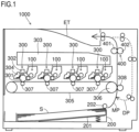
- an image forming apparatus 1000 of this embodiment includes a developing device 100.
- the developing device 100 forms a toner image.
- the developing device 100 feeds toner to an electrostatic latent image so as to develop the same.
- a structure of the developing device 100 will be described later in detail.
- the image forming apparatus 1000 includes a main conveying path MP.
- the main conveying path MP is schematically illustrated by a solid arrow.
- a duplex printing conveying path DP which will be described later, is schematically illustrated by a broken arrow.
- the image forming apparatus 1000 includes a paper feed cassette 200.
- the paper feed cassette 200 is attachable and detachable from a main body of the image forming apparatus 1000.
- the paper feed cassette 200 stores sheets.
- the sheet in the paper feed cassette 200 is denoted by S.
- the image forming apparatus 1000 feeds the sheet in the paper feed cassette 200 to the main conveying path MP, and conveys the sheet along the main conveying path MP. Further, the image forming apparatus 1000 performs printing on the sheet that is being conveyed.
- As the sheet that is used by the image forming apparatus 1000 for printing there are copy paper, coated paper, OHP sheets, cardboard, postcards, tracing paper, and the like.
- a lift plate 201 is disposed inside the paper feed cassette 200. Inside the paper feed cassette 200, the sheets are placed on the lift plate 201.
- the lift plate 201 pivots about a fulcrum at one end (i.e., an upstream side in a paper feed direction or a rear end side of the sheet), so that the other end (i.e., a downstream side in the paper feed direction or a front end side of the sheet) moves up and down.
- a paper feed roller 202 On the downstream side of the paper feed cassette 200 in the paper feed direction (at a sheet feed port), a paper feed roller 202 is disposed.
- the lift plate 201 moves upward, the sheet on the lift plate 201 contacts the outer circumferential surface of the paper feed roller 202.
- the paper feed roller 202 rotates in contact with the sheet. In this way, the paper feed cassette 200 sends out the sheet.
- the image forming apparatus 1000 includes four image forming units 300 corresponding to cyan, magenta, yellow, and black colors, respectively. Each of the image forming units 300 forms a toner image of the corresponding color. In the following description, one of the image forming units 300 is noted, and its structure is described. The individual image forming units 300 have the same basic structure, and hence descriptions of structures of other image forming units 300 are omitted by referring to the following description.
- the image forming unit 300 includes a photosensitive drum 301, a charging device 302, an exposure device 303, and a cleaning device 304.
- the photosensitive drum 301 corresponds to an "image carrier".
- the developing device 100 is a component of the image forming unit 300.
- the photosensitive drum 301 is supported in a rotatable manner.
- the charging device 302 charges the outer circumferential surface of the photosensitive drum 301.
- the exposure device 303 forms an electrostatic latent image on the outer circumferential surface of the photosensitive drum 301.
- the developing device 100 develops the electrostatic latent image on the outer circumferential surface of the photosensitive drum 301 into a toner image.
- the cleaning device 304 cleans the outer circumferential surface of the photosensitive drum 301.
- the image forming apparatus 1000 includes an intermediate transfer belt 305.
- the intermediate transfer belt 305 is an endless belt.
- the intermediate transfer belt 305 is stretched around a plurality of rollers including a drive roller 306 (the other roller is not denoted by a reference numeral), and is supported in a rotatable manner.
- the intermediate transfer belt 305 contacts the outer circumferential surface of the photosensitive drum 301 and rotates in this state.
- the drive roller 306 is supplied with driving force from a belt motor (not shown) so as to rotate. When the drive roller 306 rotates, the intermediate transfer belt 305 is driven to rotate.
- the image forming apparatus 1000 includes primary transfer rollers 307.
- the primary transfer rollers 307 are assigned to cyan, magenta, yellow, and black colors, respectively.
- the primary transfer rollers 307 are disposed on the inner periphery side of the intermediate transfer belt 305.
- Each of the primary transfer rollers 307 is disposed to face the photosensitive drum 301 of the corresponding color via the intermediate transfer belt 305.
- the image forming apparatus 1000 includes a secondary transfer roller 308.
- the secondary transfer roller 308 is pressed to contact the outer circumferential surface of the intermediate transfer belt 305, so as to form a transfer nip between itself and the intermediate transfer belt 305.
- the main conveying path MP passes through the transfer nip.
- Each of the primary transfer rollers 307 primarily transfers the toner image of the corresponding color from the photosensitive drum 301 to the outer circumferential surface of the intermediate transfer belt 305.
- the intermediate transfer belt 305 carries the toner image on its outer circumferential surface and rotates.
- the secondary transfer roller 308 forms a transfer electric field between itself and the intermediate transfer belt 305, so as to secondarily transfer the toner image to the sheet that is passing through the transfer nip.
- the image forming apparatus 1000 includes a fixing unit 400.
- the fixing unit 400 includes a fixing roller 401 and a pressure roller 402.
- the fixing roller 401 has a heater embedded inside.
- the pressure roller 402 is pressed to contact the fixing roller 401, so as to form a fixing nip between itself and the fixing roller 401.
- the sheet fed from the paper feed cassette 200 is conveyed and enters the transfer nip. Further, when the sheet passes through the transfer nip, printing on the sheet is performed. In this case, the toner image on the outer circumferential surface of the photosensitive drum 301 is transferred to the sheet. After that, the sheet enters the fixing nip, and the sheet is heated and pressed. In this way, the toner image is fixed to the sheet.
- the sheet after printing is discharged onto a discharge tray ET.
- the image forming apparatus 1000 can perform a duplex printing job, i.e., printing toner images on both sides of the sheet, as a print job.
- the image forming apparatus 1000 includes a duplex printing conveying path DP.
- the duplex printing conveying path DP branches off from the main conveying path MP on the downstream side of the fixing nip in the sheet conveying direction. Further, the duplex printing conveying path DP joins the main conveying path MP on the upstream side of the transfer nip in the sheet conveying direction.
- the sheet passes through the transfer nip only once, and the transferring process is performed once to the sheet that is passing through the transfer nip. After the first transferring process, the sheet is discharged as it is onto the discharge tray ET.
- the transferring process is performed once to each of the front and back sides of the sheet, and hence the sheet passes through the transfer nip twice. Specifically, when the sheet passes through the transfer nip first time, the transferring process is performed to one surface of the sheet. After the first transferring process, before the sheet is completed discharged onto the discharge tray ET after the rear end of the sheet has passed the fixing nip, the sheet is switched back. In this way, the sheet is pulled into the duplex printing conveying path DP from the rear end.
- the sheet is conveyed along the duplex printing conveying path DP. Further, the sheet is returned to the main conveying path MP on the upstream side of the transfer nip in the sheet conveying direction. After returning to the main conveying path MP, the sheet passes through the transfer nip again. At this time, the front and back sides of the sheet are reversed from the last time the sheet passed through the transfer nip. In this way, when the sheet passes through the transfer nip second time, the transferring process is performed to the other surface opposite to the one surface of the sheet.
- the developing device 100 includes a developing container 1.
- the developing container 1 stores developer containing toner.
- the developing container 1 has a storage space inside.
- the developer stored in the developing container 1 is nonmagnetic one-component developer containing only the toner.
- a stirring puddle SP is disposed in the storage space of the developing container 1.
- the stirring puddle SP stirs the toner in the storage space.
- a not-shown toner replenishment device replenishes the toner from a toner container to the storage space.
- the developing container 1 has an opening on the side on which the photosensitive drum 301 is disposed.
- the opening of the developing container 1 is a toner feed opening to the photosensitive drum 301.
- the developing device 100 includes a developing roller 2 and a feed roller 20.
- the feed roller 20 and the developing roller 2 are arranged side by side in this order from the inside to the outside of the developing container 1.
- the developing roller 2 is disposed so that its outer circumferential surface faces the outer circumferential surface of the feed roller 20, and that its outer circumferential surface faces the outer circumferential surface of the photosensitive drum 301.
- the developing roller 2 is disposed between the feed roller 20 and the photosensitive drum 301.
- the developing roller 2 is disposed at the opening of the developing container 1, while the feed roller 20 is disposed inside the developing container 1.
- the feed roller 20 is supported by the developing container 1 in a rotatable manner. When printing is performed, the feed roller 20 rotates in one direction (a counterclockwise direction in FIG. 2 ). In addition, the feed roller 20 carries the toner in the storage space on its outer circumferential surface. The feed roller 20 carries the toner on its outer circumferential surface and rotates, so as to feed the toner to the developing roller 2.
- the developing roller 2 is supported by the developing container 1 in a rotatable manner.
- the developing roller 2 rotates in the same direction as the feed roller 20 (in the counterclockwise direction in FIG. 2 ).
- moving directions of the outer circumferential surfaces of the developing roller 2 and the feed roller 20 are opposite to each other, at the position where the developing roller 2 and the feed roller 20 face each other.
- Each of the developing roller 2 and the feed roller 20 can rotate about an axis extending in parallel to a first direction D1.
- the direction perpendicular to the paper is the first direction D1.
- the developing roller 2 receives the toner fed from the feed roller 20, and carries the toner on its outer circumferential surface.
- the developing roller 2 carries the toner on its outer circumferential surface and rotates, so as to feed the toner to the photosensitive drum 301.
- the developing roller 2 includes a rotation shaft (without a reference numeral) and a roller member (without a reference numeral).
- the rotation shaft extends in parallel to the first direction D1.
- the roller member is a cylindrical member and is attached to the rotation shaft. The roller member rotates together with the rotation shaft.
- the roller member has a base rubber (such as silicone rubber). On the surface of the base rubber, a coat layer is formed using a rough coat material such as polyurethane. In other words, the developing roller 2 has the rough outer circumferential surface. In this way, the toner is carried on the outer circumferential surface of the developing roller 2. On the outer circumferential surface of the developing roller 2, a toner layer is formed.
- the developing device 100 includes a regulating blade 3.
- the regulating blade 3 is a plate-like member.
- the regulating blade 3 is made of sheet metal.
- the regulating blade 3 is formed by machining a metal sheet.
- the regulating blade 3 is a combination of two metal sheets having different thicknesses.
- the regulating blade 3 has a longitudinal direction in the first direction D1. In other words, the regulating blade 3 has the longitudinal direction parallel to an axis direction of the developing roller 2. The regulating blade 3 extends from one end side to the other end side in the axis direction of the developing roller 2.
- the regulating blade 3 is attached to the developing container 1.
- the regulating blade 3 extends from the side attached to the developing container 1 toward the developing roller 2.
- the regulating blade 3 allows an end part, which is opposite to the side attached to the developing container 1, to make a surface contact with the outer circumferential surface of the developing roller 2.
- the regulating blade 3 makes surface contact with the outer circumferential surface of the developing roller 2, on the upstream side of the facing position between the developing roller 2 and the photosensitive drum 301, in a rotation direction of the developing roller 2.
- the regulating blade 3 makes surface contact with the outer circumferential surface of the developing roller 2, so as to regulate thickness of the toner layer formed on the outer circumferential surface of the developing roller 2.
- the width in the first direction D1 of a part of the regulating blade 3, which makes surface contact with the outer circumferential surface of the developing roller 2 is larger than the maximum developing width of the developing roller 2.
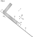
- the regulating blade 3 has a structure as illustrated in FIGS. 3 and 4 .
- FIG. 4 corresponds to a cross section of the regulating blade 3 illustrated in FIG. 3 , taken along a plane perpendicular to the first direction D1.
- the regulating blade 3 includes a mounting plate 31 and a blade plate 32.
- the mounting plate 31 and the blade plate 32 are each made of a sheet metal.
- the mounting plate 31 is made of a sheet material having a predetermined thickness.
- the blade plate 32 is made of a sheet material thinner than that of the mounting plate 31.
- the mounting plate 31 is attached to the developing container 1.
- the regulating blade 3 is attached to the developing container 1.
- An attaching structure of the regulating blade 3 to the developing container 1 is illustrated in FIGS. 5 and 6 .
- the mounting plate 31 is a part of a metal plate that is bent in an L-shape. One side part of the L-shaped metal plate with respect to a bending part (bending line) functions as the mounting plate 31.
- the mounting plate 31 is fastened to the developing container 1 using a fastening member SC such as a screw.
- the mounting plate 31 has a fastening hole 31a penetrating in the thickness direction.
- the fastening member SC is inserted in the fastening hole 31a and is engaged in a screw hole (not shown) of the developing container 1. In this way, the regulating blade 3 is attached to the developing container 1.
- the fastening hole 31a corresponds to a "fastening part".
- the mounting plate 31 has a positioning hole 31b penetrating in the thickness direction.
- a positioning pin PN of the developing container 1 is inserted in the positioning hole 31b.
- the regulating blade 3 is positioned to the developing container 1.
- the positioning hole 31b corresponds to a "positioning part".
- the blade plate 32 is joined to one surface 310 of the mounting plate 31.
- the blade plate 32 protrudes from the mounting plate 31 in a second direction D2 that is parallel to the one surface 310 and is perpendicular to the first direction D1.
- one end of the blade plate 32 in the second direction D2 is a fixed end, while the other end in the second direction D2 is a free end.
- the second direction D2 corresponds to a short direction perpendicular to the longitudinal direction of the regulating blade 3.
- the one end part of the blade plate 32 in the second direction D2 is joined (i.e., fixed) to the one surface 310 of the mounting plate 31.
- a spot welding method is used as a method of joining the blade plate 32 to the mounting plate 31.
- other method may be used to join the blade plate 32 to the mounting plate 31.
- the other end part of the blade plate 32 in the second direction D2 makes surface contact with the outer circumferential surface of the developing roller 2.
- the other end part of the blade plate 32 in the second direction D2 is curved in the direction separating from the outer circumferential surface of the developing roller 2.
- the curved part of the other end part of the blade plate 32 in the second direction D2 makes surface contact with the outer circumferential surface of the developing roller 2.
- the regulating blade 3 is constituted of two metal sheets having different thicknesses (i.e., the mounting plate 31 and the blade plate 32).
- the regulating blade 3 due to a thickness difference between the mounting plate 31 (thicker plate) and the blade plate 32 (thinner plate), the regulating blade 3 has a step.
- the developing container 1 in the state where the regulating blade 3 is attached to the developing container 1, a part of the developing container 1 faces the step part 30 of the regulating blade 3, in a third direction D3 that is perpendicular to the first direction D1 and the second direction D2.
- the developing container 1 has a facing part 10 that faces the step part 30 in the third direction D3 (see FIG. 7 ).
- the thickness direction of the step part 30 of the regulating blade 3 is identical to the facing direction between the step part 30 and the facing part 10 (i.e., the third direction D3).
- the toner passes through in the second direction D2 between the regulating blade 3 and the facing part 10 in the third direction D3.
- the toner may leak from the inside to the outside of the developing container 1.
- the leakage of the toner can be suppressed if the regulating blade 3 is brought into intimate contact with the facing part 10, but it is difficult to bring the regulating blade 3 into intimate contact with the facing part 10.
- the toner may pass through a gap between the developing container 1 and the developing roller 2 in the first direction D1, so as to leak from the inside to the outside of the developing container 1.
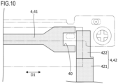
- the developing device 100 includes a seal member 4 as illustrated in FIGS. 8 to 11 .
- the seal member 4 seals a gap generated between the developing container 1 and the regulating blade 3.
- the seal member 4 is squeezed and disposed between the regulating blade 3 and the facing part 10 in the third direction D3.
- the seal member 4 includes a back seal member 41 and end part seal members 42.
- the back seal member 41 and the end part seal members 42 are separated from each other.
- the back seal member 41 and the end part seal members 42 are made of an elastic material such as polyurethane foam, though this is not a limitation. Other elastic material may be used as a constituent material of the back seal member 41 and the end part seal members 42.
- the back seal member 41 has a longitudinal direction in the first direction D1. Substantially all part of the back seal member 41 is squeezed and disposed between the regulating blade 3 and the facing part 10 in the third direction D3.
- the end part seal members 42 are respectively disposed at one end side and the other end side of the back seal member 41 in the first direction D1. In other words, there are two end part seal members 42.
- the end part seal member 42 is partially squeezed and disposed between the regulating blade 3 and the facing part 10 in the third direction D3. As the seal member 4 is disposed between the regulating blade 3 and the facing part 10 in the third direction D3, it is possible to prevent the toner from passing through in the second direction D2 between the regulating blade 3 and the facing part 10 in the third direction D3.
- the end part seal members 42 respectively have first parts 421, which contact the outer circumferential surface of the developing roller 2 at the end parts in the first direction D1.
- One of the first parts 421 contacts the outer circumferential surface of the developing roller 2 at one end part in the first direction D1, and the other first part 421 contacts the outer circumferential surface of the developing roller 2 at the other end part in the first direction D1.
- Each of the first parts 421 contacts the outer circumferential surface of the developing roller 2 at the end part in the first direction D1, from a side opposite to the side on which the photosensitive drum 301 is disposed, with respect to the developing roller 2. In this way, it is possible to prevent the toner from leaking to the outside of the developing container 1 from the end side of the developing roller 2 in the first direction D1.
- the end part seal members 42 respectively have second parts 422, which are disposed adjacent in the first direction D1 to end surfaces of the back seal member 41 in the first direction D1.
- One of the second parts 422 is disposed adjacent in the first direction D1 to one end surface of the back seal member 41 in the first direction D1.
- the other second part 422 is disposed adjacent in the first direction D1 to the other end surface of the back seal member 41 in the first direction D1.
- the back seal member 41 is sandwiched between the pair of second parts 422 in the first direction D1.
- the second parts 422 of the end part seal members 42 are partially squeezed and disposed between the regulating blade 3 and the facing part 10 in the third direction D3.
- the developing device 100 includes a resin member 5 to seal a gap G generated between the regulating blade 3 and the facing part 10.
- a resin member 5 to seal a gap G generated between the regulating blade 3 and the facing part 10.
- FIG. 13 schematically illustrates a cross section along A-A line in FIG. 12
- FIG. 14 schematically illustrates a cross section along B-B line in FIG. 12 .
- the compression amount of the back seal member 41 is larger than that between the blade plate 32 and the facing part 10 in the third direction D3.
- the gap G extending in the first direction D1 is generated in a part of the back seal member 41 around the step part 30.
- the gap G is generated due to the thickness difference between the mounting plate 31 and the blade plate 32.
- the toner in the developing container 1 may be collected in the gap G. If the toner is collected in the gap G, the toner may move along the gap G in the first direction D1. If there is not the resin member 5, the toner moving along the gap G in the first direction D1 may be scattered from the end surface of the back seal member 41 in the first direction D1. In other words, a toner passage may be formed from the end surface of the back seal member 41 in the first direction D1 to the outside via the gap G. As a result, the toner may leak from the inside to the outside of the developing container 1.
- the resin member 5 is formed by curing liquid resin.
- a constituent material of the resin member 5 is a thermoplastic resin called hot melt or the like, though this is not a limitation.
- the constituent material of the resin member 5 may be a thermosetting resin.
- the resin member 5 is disposed in an area defined by the constituent material of the seal member 4.
- the seal member 4 has a resin placement area 40.
- the resin member 5 is disposed in the resin placement area 40.
- the resin placement area 40 is an area that penetrates the seal member 4 in the third direction D3 and is surrounded by the constituent material of the seal member 4 from the first direction D1 and the second direction D2.
- the resin placement area 40 is disposed at each of one end part and the other end part of the seal member 4 in the first direction D1.
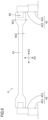
- the back seal member 41 has recesses respectively at one end part and the other end part in the first direction D1, each of which is recessed from the end surface in the first direction D1 inward in the first direction D1, and penetrates in the third direction D3 (see FIG. 9 ).
- Each recess opening on each of one side and the other side in the first direction D1 of the back seal member 41 is covered by the end surface in the first direction D1 of the end part seal member 42 disposed on the same side (i.e., the end surface of the second part 422 in the first direction D1).
- the resin placement area 40 is constituted of an area surrounded by the inner wall surface of the recess of the back seal member 41 and the end surface of the end part seal member 42 in the first direction D1.
- the resin placement area 40 is sealed by the regulating blade 3 from one side in the third direction D3. Further, the resin placement area 40 is disposed at a position overlapping the step part 30. Note that the other side of the resin placement area 40 in the third direction D3 is sealed by the facing part 10.
- a process for manufacturing the developing device 100 includes the step of attaching the regulating blade 3 to the developing container 1.
- the seal member 4 is disposed first between the regulating blade 3 and the facing part 10 in the third direction D3, so that the resin placement area 40 overlaps the step part 30.
- the regulating blade 3 is attached to the developing container 1 (i.e., using the fastening member SC, the regulating blade 3 is fastened to the developing container 1), so that the seal member 4 is squeezed in the third direction D3.
- the liquid resin is filled and cured in the resin placement area 40 so as to form the resin member 5.
- a through hole 30a of the regulating blade 3 is used as an inlet for filling the liquid resin into the resin placement area 40. In this way, the resin member 5 disposed in the resin placement area 40 can be obtained.
- the resin placement area 40 is disposed in the seal member 4, so as to dispose the resin member 5 in the resin placement area 40, and hence the toner passage from the end surface of the back seal member 41 in the first direction D1 to the outside via the gap G is closed.
- the toner is prevented from moving through the gap G and scattering from the end surface of the back seal member 41 in the first direction D1.
- the leakage of the toner from the inside to the outside of the developing container 1 is suppressed, it is possible to suppress contamination of the inside of the image forming apparatus 1000 by the toner. In addition, it is possible to prevent the toner from leaking inside of the apparatus and adhering to the sheet. In other words, contamination of the sheet can be suppressed.
- the developing container 1 is not required to have a shape for disposing the resin member 5. In this way, the resin member 5 can easily be disposed. In other words, with a simple structure, the toner can be prevented from leaking from the inside to the outside of the developing container 1.
- the resin placement area 40 in which the liquid resin to be the resin member 5 is filled i.e., the resin placement area 40 in which the resin member 5 is disposed
- the use amount of the liquid resin to be the resin member 5 can be reduced.
- the liquid resin can be quickly cured.
- the cost can be reduced.
- the through hole 30a is formed in the regulating blade 3 so as to penetrate in the third direction D3.
- the through hole 30a is formed at a position overlapping the resin placement area 40.
- the through hole 30a functions as the inlet for filling the liquid resin to be the resin member 5.
- the liquid resin to be the resin member 5 is filled into the resin placement area 40 through the through hole 30a.
- the resin member 5 is disposed in the resin placement area 40. In this way, the resin member 5 can easily be disposed in the resin placement area 40.
- the through hole 30a is constituted of a first through hole (without a reference numeral) formed in the mounting plate 31 and a second through hole (without a reference numeral) formed in the blade plate 32.
- the first through hole and the second through hole are used in the step of joining the mounting plate 31 to the blade plate 32.
- the first through hole and the second through hole function as positioning holes.
- a positioning pin is inserted into the first through hole and the second through hole, and in this state the blade plate 32 is welded to the mounting plate 31.
- the resin placement area 40 is formed as an area surrounded by the inner wall surface of the recess in the back seal member 41 and the end surface of the end part seal member 42 in the first direction D1, even if there is a gap between the back seal member 41 and the end part seal member 42 in the first direction D1, the liquid resin filled in the resin placement area 40 enters the gap between the back seal member 41 and the end part seal member 42 in the first direction D1, and is cured so as to seal the gap. In this way, it is possible to prevent the toner from leaking through the gap between the back seal member 41 and the end part seal member 42 in the first direction D1. As a result, it is possible to further prevent the toner from leaking from the inside to the outside of the developing container 1.
- the end part of the back seal member 41 in the first direction D1 has a larger width in the second direction D2 than other part (see FIG. 9 ). In this way, the resin placement area 40 can easily be formed in the end part of the back seal member 41 in the first direction D1.
- the width in the second direction D2 of the end part of the back seal member 41 in the first direction D1 is denoted by W1
- the width in the second direction D2 of the other part is denoted by W2.
- the resin placement area 40 is disposed at a position not overlapping the fastening hole 31a and the positioning hole 31b. In this way, the regulating blade 3 is appropriately fastened and positioned to the developing container 1.
Landscapes
- Physics & Mathematics (AREA)
- General Physics & Mathematics (AREA)
- Dry Development In Electrophotography (AREA)
Abstract
A developing device (100) includes a developing container (1), a developing roller (2), a regulating blade (3), a seal member (4), and a resin member (5). The regulating blade (3) includes a mounting plate (31) and a blade plate (32). The developing container (1) has a facing part (10) facing a step part (30) due to thickness difference between the mounting plate (31) and the blade plate (32). The seal member (4) has a resin placement area (40), and is squeezed between the regulating blade (3) and the facing part (10). The resin placement area (40) is an area that penetrates the seal member (4) and is surrounded by the seal member (4). The resin placement area (40) overlaps the step part (30).
Description
- The present disclosure relates to a developing device, an image forming apparatus, and a method for manufacturing a developing device.
- A conventional developing device stores toner in a developing container. The developing container supports a developing roller in a rotatable manner. The developing roller carries the toner on its outer circumferential surface and rotates. In addition, the developing container is equipped with a regulating blade. The regulating blade regulates thickness of the toner layer on the developing roller.
- A developing device according to a first aspect of the present disclosure includes a developing container, a developing roller, a regulating blade, a seal member, and a resin member. The developing container stores developer containing toner. The developing roller is supported by the developing container and is capable of rotating about an axis extending in parallel to a first direction, so as to feed the toner to an image carrier, by carrying the toner on its outer circumferential surface and rotating. The regulating blade is attached to the developing container, and has a plate-like shape whose longitudinal direction is the first direction. The regulating blade allows an end part opposite to the side attached to the developing container to make a surface contact with the outer circumferential surface of the developing roller, so as to regulate thickness of the toner layer formed on the outer circumferential surface of the developing roller. The seal member is made of elastic material so as to seal a gap between the developing container and the regulating blade. The resin member is formed by curing liquid resin. The regulating blade includes a mounting plate and a blade plate. The mounting plate is attached to the developing container. The blade plate is made of a sheet material thinner than the mounting plate. The blade plate is joined to one surface of the mounting plate, and protrudes from the mounting plate in a second direction parallel to the one surface and perpendicular to the first direction, so as to make a surface contact with the outer circumferential surface of the developing roller. The developing container has a facing part that faces a step part of the regulating blade, which includes a step due to a thickness difference between the mounting plate and the blade plate, in a third direction perpendicular to the first direction and the second direction. The seal member has a resin placement area in which the resin member is disposed, at an end part in the first direction, and is squeezed and disposed between the regulating blade and the facing part in the third direction. The resin placement area is an area that penetrates the seal member in the third direction and is surrounded by a constituent material of the seal member from the first direction and the second direction. The resin placement area is disposed at a position overlapping the step part.
- An image forming apparatus according to a second aspect of the present disclosure includes the developing device described above.
- A method for manufacturing a developing device according to a third aspect of the present disclosure is a method for manufacturing a developing device including: a developing container for storing developer containing toner; a developing roller supported by the developing container in a rotatable manner about an axis extending in parallel to a first direction, so as to feed the toner to an image carrier by carrying the toner on its outer circumferential surface and rotating; a regulating blade attached to the developing container, the regulating blade having a plate-like shape whose longitudinal direction is the first direction, the regulating blade allowing an end part opposite to the side attached to the developing container to make a surface contact with the outer circumferential surface of the developing roller, so as to regulate thickness of the toner layer formed on the outer circumferential surface of the developing roller; a seal member made of elastic material so as to seal a gap between the developing container and the regulating blade; and a resin member formed by curing liquid resin. The regulating blade includes a mounting plate attached to the developing container, and a blade plate made of a sheet material thinner than the mounting plate. The blade plate is joined to one surface of the mounting plate, and protrudes from the mounting plate in a second direction parallel to the one surface and perpendicular to the first direction, so as to make a surface contact with the outer circumferential surface of the developing roller. The developing container has a facing part that faces a step part of the regulating blade, which includes a step due to a thickness difference between the mounting plate and the blade plate, in a third direction perpendicular to the first direction and the second direction. The method includes the steps of: disposing the seal member between the regulating blade and the facing part in the third direction, so that the seal member has a resin placement area in which the resin member is disposed, at an end part in the first direction, and that the resin placement area is an area that penetrates the seal member in the third direction and is surrounded by a constituent material of the seal member from the first direction and the second direction, and that the resin placement area overlaps the step part; squeezing the seal member in the third direction by attaching the regulating blade to the developing container; and forming the resin member by filling and curing liquid resin in the resin placement area.
-
-
FIG. 1 is a schematic diagram of an image forming apparatus according to one embodiment. -
FIG. 2 is a schematic diagram of a developing device according to one embodiment. -
FIG. 3 is a perspective view of a regulating blade according to one embodiment. -
FIG. 4 is a cross-sectional view of the regulating blade according to one embodiment. -
FIG. 5 is a plan view of the developing device according to one embodiment, viewed from a photosensitive drum side. -
FIG. 6 is an enlarged view of a mounting part and its vicinity of the regulating blade to a developing container according to one embodiment. -
FIG. 7 is an enlarged perspective view of a facing part and its vicinity of the developing container according to one embodiment. -
FIG. 8 is a diagram illustrating the developing container illustrated inFIG. 7 , in which a seal member is disposed. -
FIG. 9 is a plan view of the seal member according to one embodiment. -
FIG. 10 is a schematic diagram of an end part and its vicinity of the seal member in a first direction according to one embodiment. -
FIG. 11 is a schematic diagram illustrating a positional relationship between the seal member illustrated inFIG. 10 and the regulating blade. -
FIG. 12 is a schematic diagram illustrating a positional relationship between the seal member illustrated inFIG. 10 and a resin member. -
FIG. 13 is a diagram schematically illustrating a cross section along A-A line inFIG. 12 . -
FIG. 14 is a diagram schematically illustrating a cross section along B-B line inFIG. 12 . - Hereinafter, a structure of an image forming apparatus is described, which includes a developing device according to one embodiment of the present disclosure. In the following description, a tandem type color printer is exemplified for convenience sake. However, the present disclosure can be applied not only to a color printer but also to a monochrome printer. In addition, the present disclosure can be applied to other image forming apparatus different from a printer, such as a copier, a facsimile machine, or a multifunction peripheral having those functions.
- As illustrated in
FIG. 1 , animage forming apparatus 1000 of this embodiment includes a developingdevice 100. The developingdevice 100 forms a toner image. In other words, the developingdevice 100 feeds toner to an electrostatic latent image so as to develop the same. A structure of the developingdevice 100 will be described later in detail. - The
image forming apparatus 1000 includes a main conveying path MP. InFIG. 1 , the main conveying path MP is schematically illustrated by a solid arrow. A duplex printing conveying path DP, which will be described later, is schematically illustrated by a broken arrow. - The
image forming apparatus 1000 includes apaper feed cassette 200. Thepaper feed cassette 200 is attachable and detachable from a main body of theimage forming apparatus 1000. Thepaper feed cassette 200 stores sheets. InFIG. 1 , the sheet in thepaper feed cassette 200 is denoted by S. Theimage forming apparatus 1000 feeds the sheet in thepaper feed cassette 200 to the main conveying path MP, and conveys the sheet along the main conveying path MP. Further, theimage forming apparatus 1000 performs printing on the sheet that is being conveyed. As the sheet that is used by theimage forming apparatus 1000 for printing, there are copy paper, coated paper, OHP sheets, cardboard, postcards, tracing paper, and the like. - Inside the
paper feed cassette 200, alift plate 201 is disposed. Inside thepaper feed cassette 200, the sheets are placed on thelift plate 201. Thelift plate 201 pivots about a fulcrum at one end (i.e., an upstream side in a paper feed direction or a rear end side of the sheet), so that the other end (i.e., a downstream side in the paper feed direction or a front end side of the sheet) moves up and down. - On the downstream side of the
paper feed cassette 200 in the paper feed direction (at a sheet feed port), apaper feed roller 202 is disposed. When thelift plate 201 moves upward, the sheet on thelift plate 201 contacts the outer circumferential surface of thepaper feed roller 202. Thepaper feed roller 202 rotates in contact with the sheet. In this way, thepaper feed cassette 200 sends out the sheet. - The
image forming apparatus 1000 includes fourimage forming units 300 corresponding to cyan, magenta, yellow, and black colors, respectively. Each of theimage forming units 300 forms a toner image of the corresponding color. In the following description, one of theimage forming units 300 is noted, and its structure is described. The individualimage forming units 300 have the same basic structure, and hence descriptions of structures of otherimage forming units 300 are omitted by referring to the following description. - The
image forming unit 300 includes aphotosensitive drum 301, acharging device 302, anexposure device 303, and acleaning device 304. Thephotosensitive drum 301 corresponds to an "image carrier". The developingdevice 100 is a component of theimage forming unit 300. - The
photosensitive drum 301 is supported in a rotatable manner. The chargingdevice 302 charges the outer circumferential surface of thephotosensitive drum 301. Theexposure device 303 forms an electrostatic latent image on the outer circumferential surface of thephotosensitive drum 301. The developingdevice 100 develops the electrostatic latent image on the outer circumferential surface of thephotosensitive drum 301 into a toner image. Thecleaning device 304 cleans the outer circumferential surface of thephotosensitive drum 301. - The
image forming apparatus 1000 includes anintermediate transfer belt 305. Theintermediate transfer belt 305 is an endless belt. Theintermediate transfer belt 305 is stretched around a plurality of rollers including a drive roller 306 (the other roller is not denoted by a reference numeral), and is supported in a rotatable manner. Theintermediate transfer belt 305 contacts the outer circumferential surface of thephotosensitive drum 301 and rotates in this state. Thedrive roller 306 is supplied with driving force from a belt motor (not shown) so as to rotate. When thedrive roller 306 rotates, theintermediate transfer belt 305 is driven to rotate. - The
image forming apparatus 1000 includesprimary transfer rollers 307. Theprimary transfer rollers 307 are assigned to cyan, magenta, yellow, and black colors, respectively. Theprimary transfer rollers 307 are disposed on the inner periphery side of theintermediate transfer belt 305. Each of theprimary transfer rollers 307 is disposed to face thephotosensitive drum 301 of the corresponding color via theintermediate transfer belt 305. - The
image forming apparatus 1000 includes asecondary transfer roller 308. Thesecondary transfer roller 308 is pressed to contact the outer circumferential surface of theintermediate transfer belt 305, so as to form a transfer nip between itself and theintermediate transfer belt 305. The main conveying path MP passes through the transfer nip. - Each of the
primary transfer rollers 307 primarily transfers the toner image of the corresponding color from thephotosensitive drum 301 to the outer circumferential surface of theintermediate transfer belt 305. Theintermediate transfer belt 305 carries the toner image on its outer circumferential surface and rotates. Thesecondary transfer roller 308 forms a transfer electric field between itself and theintermediate transfer belt 305, so as to secondarily transfer the toner image to the sheet that is passing through the transfer nip. - In addition, the
image forming apparatus 1000 includes a fixingunit 400. The fixingunit 400 includes a fixingroller 401 and apressure roller 402. The fixingroller 401 has a heater embedded inside. Thepressure roller 402 is pressed to contact the fixingroller 401, so as to form a fixing nip between itself and the fixingroller 401. - During printing by the
image forming apparatus 1000, the sheet fed from thepaper feed cassette 200 is conveyed and enters the transfer nip. Further, when the sheet passes through the transfer nip, printing on the sheet is performed. In this case, the toner image on the outer circumferential surface of thephotosensitive drum 301 is transferred to the sheet. After that, the sheet enters the fixing nip, and the sheet is heated and pressed. In this way, the toner image is fixed to the sheet. The sheet after printing is discharged onto a discharge tray ET. - Besides a one-side printing job, i.e., printing a toner image only on one side of the sheet, the
image forming apparatus 1000 can perform a duplex printing job, i.e., printing toner images on both sides of the sheet, as a print job. To perform the duplex printing job, theimage forming apparatus 1000 includes a duplex printing conveying path DP. - The duplex printing conveying path DP branches off from the main conveying path MP on the downstream side of the fixing nip in the sheet conveying direction. Further, the duplex printing conveying path DP joins the main conveying path MP on the upstream side of the transfer nip in the sheet conveying direction.
- If the executing job is the one-side printing job, the sheet passes through the transfer nip only once, and the transferring process is performed once to the sheet that is passing through the transfer nip. After the first transferring process, the sheet is discharged as it is onto the discharge tray ET.
- If the executing job is the duplex printing job, the transferring process is performed once to each of the front and back sides of the sheet, and hence the sheet passes through the transfer nip twice. Specifically, when the sheet passes through the transfer nip first time, the transferring process is performed to one surface of the sheet. After the first transferring process, before the sheet is completed discharged onto the discharge tray ET after the rear end of the sheet has passed the fixing nip, the sheet is switched back. In this way, the sheet is pulled into the duplex printing conveying path DP from the rear end.
- After that, the sheet is conveyed along the duplex printing conveying path DP. Further, the sheet is returned to the main conveying path MP on the upstream side of the transfer nip in the sheet conveying direction. After returning to the main conveying path MP, the sheet passes through the transfer nip again. At this time, the front and back sides of the sheet are reversed from the last time the sheet passed through the transfer nip. In this way, when the sheet passes through the transfer nip second time, the transferring process is performed to the other surface opposite to the one surface of the sheet.
- As illustrated in
FIG. 2 , the developingdevice 100 includes a developingcontainer 1. The developingcontainer 1 stores developer containing toner. In other words, the developingcontainer 1 has a storage space inside. Note that the developer stored in the developingcontainer 1 is nonmagnetic one-component developer containing only the toner. - In the storage space of the developing
container 1, a stirring puddle SP is disposed. The stirring puddle SP stirs the toner in the storage space. Note that a not-shown toner replenishment device replenishes the toner from a toner container to the storage space. - The developing
container 1 has an opening on the side on which thephotosensitive drum 301 is disposed. The opening of the developingcontainer 1 is a toner feed opening to thephotosensitive drum 301. - The developing
device 100 includes a developingroller 2 and afeed roller 20. Thefeed roller 20 and the developingroller 2 are arranged side by side in this order from the inside to the outside of the developingcontainer 1. The developingroller 2 is disposed so that its outer circumferential surface faces the outer circumferential surface of thefeed roller 20, and that its outer circumferential surface faces the outer circumferential surface of thephotosensitive drum 301. In other words, the developingroller 2 is disposed between thefeed roller 20 and thephotosensitive drum 301. In further other words, the developingroller 2 is disposed at the opening of the developingcontainer 1, while thefeed roller 20 is disposed inside the developingcontainer 1. - The
feed roller 20 is supported by the developingcontainer 1 in a rotatable manner. When printing is performed, thefeed roller 20 rotates in one direction (a counterclockwise direction inFIG. 2 ). In addition, thefeed roller 20 carries the toner in the storage space on its outer circumferential surface. Thefeed roller 20 carries the toner on its outer circumferential surface and rotates, so as to feed the toner to the developingroller 2. - The developing
roller 2 is supported by the developingcontainer 1 in a rotatable manner. When printing is performed, the developingroller 2 rotates in the same direction as the feed roller 20 (in the counterclockwise direction inFIG. 2 ). As a result, moving directions of the outer circumferential surfaces of the developingroller 2 and thefeed roller 20 are opposite to each other, at the position where the developingroller 2 and thefeed roller 20 face each other. - Each of the developing
roller 2 and thefeed roller 20 can rotate about an axis extending in parallel to a first direction D1. InFIG. 2 , the direction perpendicular to the paper is the first direction D1. - The developing
roller 2 receives the toner fed from thefeed roller 20, and carries the toner on its outer circumferential surface. The developingroller 2 carries the toner on its outer circumferential surface and rotates, so as to feed the toner to thephotosensitive drum 301. In order to efficiently transfer the toner from the developingroller 2 to thephotosensitive drum 301, it is preferred to apply a predetermined developing voltage to the developingroller 2. - The developing
roller 2 includes a rotation shaft (without a reference numeral) and a roller member (without a reference numeral). The rotation shaft extends in parallel to the first direction D1. The roller member is a cylindrical member and is attached to the rotation shaft. The roller member rotates together with the rotation shaft. - For instance, the roller member has a base rubber (such as silicone rubber). On the surface of the base rubber, a coat layer is formed using a rough coat material such as polyurethane. In other words, the developing
roller 2 has the rough outer circumferential surface. In this way, the toner is carried on the outer circumferential surface of the developingroller 2. On the outer circumferential surface of the developingroller 2, a toner layer is formed. - In addition, the developing
device 100 includes aregulating blade 3. Theregulating blade 3 is a plate-like member. Theregulating blade 3 is made of sheet metal. Theregulating blade 3 is formed by machining a metal sheet. Theregulating blade 3 is a combination of two metal sheets having different thicknesses. - The
regulating blade 3 has a longitudinal direction in the first direction D1. In other words, theregulating blade 3 has the longitudinal direction parallel to an axis direction of the developingroller 2. Theregulating blade 3 extends from one end side to the other end side in the axis direction of the developingroller 2. - The
regulating blade 3 is attached to the developingcontainer 1. Theregulating blade 3 extends from the side attached to the developingcontainer 1 toward the developingroller 2. Theregulating blade 3 allows an end part, which is opposite to the side attached to the developingcontainer 1, to make a surface contact with the outer circumferential surface of the developingroller 2. - The
regulating blade 3 makes surface contact with the outer circumferential surface of the developingroller 2, on the upstream side of the facing position between the developingroller 2 and thephotosensitive drum 301, in a rotation direction of the developingroller 2. Theregulating blade 3 makes surface contact with the outer circumferential surface of the developingroller 2, so as to regulate thickness of the toner layer formed on the outer circumferential surface of the developingroller 2. Note that the width in the first direction D1 of a part of theregulating blade 3, which makes surface contact with the outer circumferential surface of the developingroller 2, is larger than the maximum developing width of the developingroller 2. - The
regulating blade 3 has a structure as illustrated inFIGS. 3 and4 . Note thatFIG. 4 corresponds to a cross section of theregulating blade 3 illustrated inFIG. 3 , taken along a plane perpendicular to the first direction D1. - The
regulating blade 3 includes a mountingplate 31 and ablade plate 32. The mountingplate 31 and theblade plate 32 are each made of a sheet metal. The mountingplate 31 is made of a sheet material having a predetermined thickness. Theblade plate 32 is made of a sheet material thinner than that of the mountingplate 31. - The mounting
plate 31 is attached to the developingcontainer 1. When the mountingplate 31 is attached to the developingcontainer 1, theregulating blade 3 is attached to the developingcontainer 1. An attaching structure of theregulating blade 3 to the developingcontainer 1 is illustrated inFIGS. 5 and6 . - The mounting
plate 31 is a part of a metal plate that is bent in an L-shape. One side part of the L-shaped metal plate with respect to a bending part (bending line) functions as the mountingplate 31. The mountingplate 31 is fastened to the developingcontainer 1 using a fastening member SC such as a screw. Specifically, the mountingplate 31 has afastening hole 31a penetrating in the thickness direction. The fastening member SC is inserted in thefastening hole 31a and is engaged in a screw hole (not shown) of the developingcontainer 1. In this way, theregulating blade 3 is attached to the developingcontainer 1. In this structure, thefastening hole 31a corresponds to a "fastening part". - In addition, the mounting
plate 31 has apositioning hole 31b penetrating in the thickness direction. In the state where the mountingplate 31 is attached to the developingcontainer 1, a positioning pin PN of the developingcontainer 1 is inserted in thepositioning hole 31b. In this way, theregulating blade 3 is positioned to the developingcontainer 1. In this structure, thepositioning hole 31b corresponds to a "positioning part". - The
blade plate 32 is joined to onesurface 310 of the mountingplate 31. Theblade plate 32 protrudes from the mountingplate 31 in a second direction D2 that is parallel to the onesurface 310 and is perpendicular to the first direction D1. In this way, one end of theblade plate 32 in the second direction D2 is a fixed end, while the other end in the second direction D2 is a free end. Note that the second direction D2 corresponds to a short direction perpendicular to the longitudinal direction of theregulating blade 3. - The one end part of the
blade plate 32 in the second direction D2 is joined (i.e., fixed) to the onesurface 310 of the mountingplate 31. For instance, as a method of joining theblade plate 32 to the mountingplate 31, a spot welding method is used. However, other method may be used to join theblade plate 32 to the mountingplate 31. - The other end part of the
blade plate 32 in the second direction D2 makes surface contact with the outer circumferential surface of the developingroller 2. For instance, the other end part of theblade plate 32 in the second direction D2 is curved in the direction separating from the outer circumferential surface of the developingroller 2. Further, the curved part of the other end part of theblade plate 32 in the second direction D2 makes surface contact with the outer circumferential surface of the developingroller 2. - In this way, the
regulating blade 3 is constituted of two metal sheets having different thicknesses (i.e., the mountingplate 31 and the blade plate 32). In this structure, due to a thickness difference between the mounting plate 31 (thicker plate) and the blade plate 32 (thinner plate), theregulating blade 3 has a step. In the following description, a part of theregulating blade 3, which has the step due to the thickness difference between the mountingplate 31 and theblade plate 32, is denoted by 30 and is referred to as astep part 30. - Note that, in the state where the
regulating blade 3 is attached to the developingcontainer 1, a part of the developingcontainer 1 faces thestep part 30 of theregulating blade 3, in a third direction D3 that is perpendicular to the first direction D1 and the second direction D2. In other words, the developingcontainer 1 has a facingpart 10 that faces thestep part 30 in the third direction D3 (seeFIG. 7 ). The thickness direction of thestep part 30 of theregulating blade 3 is identical to the facing direction between thestep part 30 and the facing part 10 (i.e., the third direction D3). - If a gap between the regulating
blade 3 and the facingpart 10 in the third direction D3 is large, the toner passes through in the second direction D2 between the regulatingblade 3 and the facingpart 10 in the third direction D3. When the toner passes through in the second direction D2 between the regulatingblade 3 and the facingpart 10 in the third direction D3, the toner may leak from the inside to the outside of the developingcontainer 1. The leakage of the toner can be suppressed if theregulating blade 3 is brought into intimate contact with the facingpart 10, but it is difficult to bring theregulating blade 3 into intimate contact with the facingpart 10. In addition, on the end sides of the developingroller 2 in the first direction D1, the toner may pass through a gap between the developingcontainer 1 and the developingroller 2 in the first direction D1, so as to leak from the inside to the outside of the developingcontainer 1. - In order to suppress such an inconvenience, the developing
device 100 includes aseal member 4 as illustrated inFIGS. 8 to 11 . Theseal member 4 seals a gap generated between the developingcontainer 1 and theregulating blade 3. Theseal member 4 is squeezed and disposed between the regulatingblade 3 and the facingpart 10 in the third direction D3. - The
seal member 4 includes aback seal member 41 and endpart seal members 42. Theback seal member 41 and the endpart seal members 42 are separated from each other. Theback seal member 41 and the endpart seal members 42 are made of an elastic material such as polyurethane foam, though this is not a limitation. Other elastic material may be used as a constituent material of theback seal member 41 and the endpart seal members 42. - The
back seal member 41 has a longitudinal direction in the first direction D1. Substantially all part of theback seal member 41 is squeezed and disposed between the regulatingblade 3 and the facingpart 10 in the third direction D3. The endpart seal members 42 are respectively disposed at one end side and the other end side of theback seal member 41 in the first direction D1. In other words, there are two endpart seal members 42. The endpart seal member 42 is partially squeezed and disposed between the regulatingblade 3 and the facingpart 10 in the third direction D3. As theseal member 4 is disposed between the regulatingblade 3 and the facingpart 10 in the third direction D3, it is possible to prevent the toner from passing through in the second direction D2 between the regulatingblade 3 and the facingpart 10 in the third direction D3. - The end
part seal members 42 respectively havefirst parts 421, which contact the outer circumferential surface of the developingroller 2 at the end parts in the first direction D1. One of thefirst parts 421 contacts the outer circumferential surface of the developingroller 2 at one end part in the first direction D1, and the otherfirst part 421 contacts the outer circumferential surface of the developingroller 2 at the other end part in the first direction D1. Each of thefirst parts 421 contacts the outer circumferential surface of the developingroller 2 at the end part in the first direction D1, from a side opposite to the side on which thephotosensitive drum 301 is disposed, with respect to the developingroller 2. In this way, it is possible to prevent the toner from leaking to the outside of the developingcontainer 1 from the end side of the developingroller 2 in the first direction D1. - The end
part seal members 42 respectively havesecond parts 422, which are disposed adjacent in the first direction D1 to end surfaces of theback seal member 41 in the first direction D1. One of thesecond parts 422 is disposed adjacent in the first direction D1 to one end surface of theback seal member 41 in the first direction D1. The othersecond part 422 is disposed adjacent in the first direction D1 to the other end surface of theback seal member 41 in the first direction D1. In other words, theback seal member 41 is sandwiched between the pair ofsecond parts 422 in the first direction D1. Thesecond parts 422 of the endpart seal members 42 are partially squeezed and disposed between the regulatingblade 3 and the facingpart 10 in the third direction D3. - As illustrated in
FIGS. 12 to 14 , the developingdevice 100 includes aresin member 5 to seal a gap G generated between the regulatingblade 3 and the facingpart 10. The specific description is given below. Note thatFIG. 13 schematically illustrates a cross section along A-A line inFIG. 12 , andFIG. 14 schematically illustrates a cross section along B-B line inFIG. 12 . - Between the mounting
plate 31 and the facingpart 10 in the third direction D3, the compression amount of theback seal member 41 is larger than that between theblade plate 32 and the facingpart 10 in the third direction D3. In this way, the gap G extending in the first direction D1 is generated in a part of theback seal member 41 around thestep part 30. The gap G is generated due to the thickness difference between the mountingplate 31 and theblade plate 32. - The toner in the developing
container 1 may be collected in the gap G. If the toner is collected in the gap G, the toner may move along the gap G in the first direction D1. If there is not theresin member 5, the toner moving along the gap G in the first direction D1 may be scattered from the end surface of theback seal member 41 in the first direction D1. In other words, a toner passage may be formed from the end surface of theback seal member 41 in the first direction D1 to the outside via the gap G. As a result, the toner may leak from the inside to the outside of the developingcontainer 1. - In order to suppress such an inconvenience, the toner passage via the gap G is sealed by the
resin member 5. Theresin member 5 is formed by curing liquid resin. For instance, a constituent material of theresin member 5 is a thermoplastic resin called hot melt or the like, though this is not a limitation. The constituent material of theresin member 5 may be a thermosetting resin. - The
resin member 5 is disposed in an area defined by the constituent material of theseal member 4. In other words, theseal member 4 has aresin placement area 40. Theresin member 5 is disposed in theresin placement area 40. Theresin placement area 40 is an area that penetrates theseal member 4 in the third direction D3 and is surrounded by the constituent material of theseal member 4 from the first direction D1 and the second direction D2. Theresin placement area 40 is disposed at each of one end part and the other end part of theseal member 4 in the first direction D1. - Specifically, the
back seal member 41 has recesses respectively at one end part and the other end part in the first direction D1, each of which is recessed from the end surface in the first direction D1 inward in the first direction D1, and penetrates in the third direction D3 (seeFIG. 9 ). Each recess opening on each of one side and the other side in the first direction D1 of theback seal member 41 is covered by the end surface in the first direction D1 of the endpart seal member 42 disposed on the same side (i.e., the end surface of thesecond part 422 in the first direction D1). Theresin placement area 40 is constituted of an area surrounded by the inner wall surface of the recess of theback seal member 41 and the end surface of the endpart seal member 42 in the first direction D1. - In addition, the
resin placement area 40 is sealed by theregulating blade 3 from one side in the third direction D3. Further, theresin placement area 40 is disposed at a position overlapping thestep part 30. Note that the other side of theresin placement area 40 in the third direction D3 is sealed by the facingpart 10. - A process for manufacturing the developing
device 100 includes the step of attaching theregulating blade 3 to the developingcontainer 1. In the step of attaching theregulating blade 3 to the developingcontainer 1, theseal member 4 is disposed first between the regulatingblade 3 and the facingpart 10 in the third direction D3, so that theresin placement area 40 overlaps thestep part 30. Next, theregulating blade 3 is attached to the developing container 1 (i.e., using the fastening member SC, theregulating blade 3 is fastened to the developing container 1), so that theseal member 4 is squeezed in the third direction D3. Next, the liquid resin is filled and cured in theresin placement area 40 so as to form theresin member 5. When the liquid resin is filled in theresin placement area 40, a throughhole 30a of theregulating blade 3 is used as an inlet for filling the liquid resin into theresin placement area 40. In this way, theresin member 5 disposed in theresin placement area 40 can be obtained. - In this embodiment, the
resin placement area 40 is disposed in theseal member 4, so as to dispose theresin member 5 in theresin placement area 40, and hence the toner passage from the end surface of theback seal member 41 in the first direction D1 to the outside via the gap G is closed. In this way, even if the toner is collected in the gap G, the toner is prevented from moving through the gap G and scattering from the end surface of theback seal member 41 in the first direction D1. In other words, it is possible to prevent the toner from leaking to the outside through the gap G between the regulatingblade 3 and theseal member 4. As a result, it is possible to prevent the toner from leaking from the inside to the outside of the developingcontainer 1. - Because the leakage of the toner from the inside to the outside of the developing
container 1 is suppressed, it is possible to suppress contamination of the inside of theimage forming apparatus 1000 by the toner. In addition, it is possible to prevent the toner from leaking inside of the apparatus and adhering to the sheet. In other words, contamination of the sheet can be suppressed. - In addition, in this embodiment, because the
resin placement area 40 is disposed in theseal member 4, the developingcontainer 1 is not required to have a shape for disposing theresin member 5. In this way, theresin member 5 can easily be disposed. In other words, with a simple structure, the toner can be prevented from leaking from the inside to the outside of the developingcontainer 1. - Further, in this embodiment, because the
resin placement area 40 in which the liquid resin to be theresin member 5 is filled (i.e., theresin placement area 40 in which theresin member 5 is disposed) is formed only in the end parts of theseal member 4, the use amount of the liquid resin to be theresin member 5 can be reduced. By reducing the use amount of the liquid resin, the liquid resin can be quickly cured. In addition, by reducing the use amount of the liquid resin, the cost can be reduced. - Here, in this embodiment, the through
hole 30a is formed in theregulating blade 3 so as to penetrate in the third direction D3. The throughhole 30a is formed at a position overlapping theresin placement area 40. The throughhole 30a functions as the inlet for filling the liquid resin to be theresin member 5. In the step of disposing theresin member 5 in theresin placement area 40, the liquid resin to be theresin member 5 is filled into theresin placement area 40 through the throughhole 30a. In other words, after attaching theregulating blade 3 to the developingcontainer 1, theresin member 5 is disposed in theresin placement area 40. In this way, theresin member 5 can easily be disposed in theresin placement area 40. - Note that the through
hole 30a is constituted of a first through hole (without a reference numeral) formed in the mountingplate 31 and a second through hole (without a reference numeral) formed in theblade plate 32. The first through hole and the second through hole are used in the step of joining the mountingplate 31 to theblade plate 32. In the step of joining the mountingplate 31 to theblade plate 32, the first through hole and the second through hole function as positioning holes. In other words, in the step of joining the mountingplate 31 to theblade plate 32, a positioning pin is inserted into the first through hole and the second through hole, and in this state theblade plate 32 is welded to the mountingplate 31. - In addition, in this embodiment, because the
resin placement area 40 is formed as an area surrounded by the inner wall surface of the recess in theback seal member 41 and the end surface of the endpart seal member 42 in the first direction D1, even if there is a gap between theback seal member 41 and the endpart seal member 42 in the first direction D1, the liquid resin filled in theresin placement area 40 enters the gap between theback seal member 41 and the endpart seal member 42 in the first direction D1, and is cured so as to seal the gap. In this way, it is possible to prevent the toner from leaking through the gap between theback seal member 41 and the endpart seal member 42 in the first direction D1. As a result, it is possible to further prevent the toner from leaking from the inside to the outside of the developingcontainer 1. - In addition, in this embodiment, the end part of the
back seal member 41 in the first direction D1 has a larger width in the second direction D2 than other part (seeFIG. 9 ). In this way, theresin placement area 40 can easily be formed in the end part of theback seal member 41 in the first direction D1. InFIG. 9 , the width in the second direction D2 of the end part of theback seal member 41 in the first direction D1 is denoted by W1, and the width in the second direction D2 of the other part is denoted by W2. - Further, in this embodiment, the
resin placement area 40 is disposed at a position not overlapping thefastening hole 31a and thepositioning hole 31b. In this way, theregulating blade 3 is appropriately fastened and positioned to the developingcontainer 1. - The embodiment disclosed herein is merely an example in every aspect, and should not be interpreted as a limitation. The scope of the present disclosure is defined not by the above description of the embodiment but by the claims, and includes all modifications within the meaning and scope equivalent to the claims.
Claims (8)
- A developing device (100) comprising:a developing container (1) configured to store developer containing toner;a developing roller (2) supported by the developing container (1) in a rotatable manner about an axis extending in parallel to a first direction (D1), so as to feed the toner to an image carrier (301) by carrying the toner on its outer circumferential surface and rotating;a regulating blade (3) attached to the developing container (1), the regulating blade having a plate-like shape whose longitudinal direction is the first direction (D1), the regulating blade allowing an end part opposite to the side attached to the developing container (1) to make a surface contact with the outer circumferential surface of the developing roller (2), so as to regulate thickness of the toner layer formed on the outer circumferential surface of the developing roller (2);a seal member (4) made of elastic material so as to seal a gap between the developing container (1) and the regulating blade (3); anda resin member (5) formed by curing liquid resin, whereinthe regulating blade (3) includes a mounting plate (31) attached to the developing container (1), and a blade plate (32) made of a sheet material thinner than the mounting plate (31),the blade plate (32) is joined to one surface (310) of the mounting plate (31), and protrudes from the mounting plate (31) in a second direction parallel to the one surface (310) and perpendicular to the first direction (D1), so as to make a surface contact with the outer circumferential surface of the developing roller (2),the developing container (1) has a facing part (10) that faces a step part (30) of the regulating blade (3), which includes a step due to a thickness difference between the mounting plate (31) and the blade plate (32), in a third direction (D3) perpendicular to the first direction (D1) and the second direction (D2),the seal member (4) has a resin placement area (40) in which the resin member (5) is disposed, at an end part in the first direction (D1), and is squeezed and disposed between the regulating blade (3) and the facing part (10) in the third direction (D3),the resin placement area (40) is an area that penetrates the seal member (4) in the third direction (D3) and is surrounded by a constituent material of the seal member (4) from the first direction (D1) and the second direction (D2), andthe resin placement area (40) is disposed at a position overlapping the step part (30).
- The developing device (100) according to claim 1, wherein the regulating blade (3) has a through hole (30a) penetrating in the third direction (D3), at a position overlapping the resin placement area (40).
- The developing device (100) according to claim 1 or 2, whereinthe seal member (4) includes a back seal member (41) whose longitudinal direction is the first direction (D1), and an end part seal member (42) adjacent in the first direction (D1) to an end surface of the back seal member (41) in the first direction (D1),the back seal member (41) has a recess that recesses from the end surface in the first direction (D1) inward in the first direction (D1), and penetrates in the third direction (D3), andthe resin placement area (40) is an area surrounded by an inner wall surface of the recess and the end surface of the end part seal member (42) in the first direction (D1).
- The developing device (100) according to claim 3, wherein an end part of the back seal member (41) in the first direction (D1) has a larger width in the second direction (D2) than other part.
- The developing device (100) according to any one of claims 1 to 4, whereinthe regulating blade (3) has a fastening part (31a) for fastening to the developing container (1) using a fastening member (SC), and a positioning part (31b) for positioning to the developing container (1), andthe resin placement area (40) is disposed at a position not overlapping the fastening part (31a) and the positioning part (31b).
- The developing device (100) according to any one of claims 1 to 5, wherein the developer is nonmagnetic one-component developer containing only nonmagnetic toner.
- An image forming apparatus (1000) comprising the developing device (100) according to any one of claims 1 to 6.
- A method for manufacturing a developing device (100) including:a developing container (1) configured to store developer containing toner;a developing roller (2) supported by the developing container (1) in a rotatable manner about an axis extending in parallel to a first direction (D1), so as to feed the toner to an image carrier (301) by carrying the toner on its outer circumferential surface and rotating;a regulating blade (3) attached to the developing container (1), the regulating blade having a plate-like shape whose longitudinal direction is the first direction (D1), the regulating blade allowing an end part opposite to the side attached to the developing container (1) to make a surface contact with the outer circumferential surface of the developing roller (2), so as to regulate thickness of the toner layer formed on the outer circumferential surface of the developing roller (2);a seal member (4) made of elastic material so as to seal a gap between the developing container (1) and the regulating blade (3); anda resin member (5) formed by curing liquid resin, whereinthe regulating blade (3) includes a mounting plate (31) attached to the developing container (1), and a blade plate (32) made of a sheet material thinner than the mounting plate (31),the blade plate (32) is joined to one surface (310) of the mounting plate (31), and protrudes from the mounting plate (31) in a second direction parallel to the one surface (310) and perpendicular to the first direction (D1), so as to make a surface contact with the outer circumferential surface of the developing roller (2), andthe developing container (1) has a facing part (10) that faces a step part (30) of the regulating blade (3), which includes a step due to a thickness difference between the mounting plate (31) and the blade plate (32), in a third direction (D3) perpendicular to the first direction (D1) and the second direction (D2), and whereinthe method comprises the steps of:disposing the seal member (4) between the regulating blade (3) and the facing part (10) in the third direction (D3), so that the seal member (4) has a resin placement area (40) in which the resin member (5) is disposed, at an end part in the first direction (D1), and that the resin placement area (40) is an area that penetrates the seal member (4) in the third direction (D3) and is surrounded by a constituent material of the seal member (4) from the first direction (D1) and the second direction (D2), and that the resin placement area (40) overlaps the step part (30);squeezing the seal member (4) in the third direction (D3) by attaching the regulating blade (3) to the developing container (1); andforming the resin member (5) by filling and curing the liquid resin in the resin placement area (40).
Applications Claiming Priority (1)
| Application Number | Priority Date | Filing Date | Title |
|---|---|---|---|
| JP2023190677A JP2025078245A (en) | 2023-11-08 | 2023-11-08 | Developing device, image forming apparatus, and method of manufacturing the developing device |
Publications (1)
| Publication Number | Publication Date |
|---|---|
| EP4553583A1 true EP4553583A1 (en) | 2025-05-14 |
Family
ID=93379108
Family Applications (1)
| Application Number | Title | Priority Date | Filing Date |
|---|---|---|---|
| EP24210526.0A Withdrawn EP4553583A1 (en) | 2023-11-08 | 2024-11-04 | Developing device, image forming apparatus, and method for manufacturing developing device |
Country Status (3)
| Country | Link |
|---|---|
| US (1) | US12510848B2 (en) |
| EP (1) | EP4553583A1 (en) |
| JP (1) | JP2025078245A (en) |
Citations (4)
| Publication number | Priority date | Publication date | Assignee | Title |
|---|---|---|---|---|
| JP2001140856A (en) * | 1999-11-18 | 2001-05-22 | Inoac Corp | Laminated roller and manufacturing method thereof |
| JP2004126003A (en) * | 2002-09-30 | 2004-04-22 | Canon Inc | Developing unit, process cartridge and image forming apparatus |
| US20060291895A1 (en) * | 2004-07-29 | 2006-12-28 | Brother Kogyo Kabushiki Kaisha | Developing apparatus and assembly method of developing apparatus |
| US20090092411A1 (en) * | 2005-05-09 | 2009-04-09 | Canon Kabushiki Kaisha | Developer container, process cartridge, image forming apparatus and manufacturing method for developer container |
Family Cites Families (4)
| Publication number | Priority date | Publication date | Assignee | Title |
|---|---|---|---|---|
| JP5063792B2 (en) * | 2010-05-18 | 2012-10-31 | キヤノン株式会社 | Developing device, process cartridge, developing device, and process cartridge remanufacturing method |
| PH12014501013A1 (en) * | 2011-11-09 | 2014-06-23 | Canon Kk | Cartridge and unit |
| JP6057651B2 (en) * | 2012-10-01 | 2017-01-11 | キヤノン株式会社 | Process cartridge and process cartridge manufacturing method |
| JP6953262B2 (en) | 2017-10-03 | 2021-10-27 | キヤノン株式会社 | Frame, developing unit and manufacturing method of frame |
-
2023
- 2023-11-08 JP JP2023190677A patent/JP2025078245A/en active Pending
-
2024
- 2024-11-01 US US18/935,056 patent/US12510848B2/en active Active
- 2024-11-04 EP EP24210526.0A patent/EP4553583A1/en not_active Withdrawn
Patent Citations (4)
| Publication number | Priority date | Publication date | Assignee | Title |
|---|---|---|---|---|
| JP2001140856A (en) * | 1999-11-18 | 2001-05-22 | Inoac Corp | Laminated roller and manufacturing method thereof |
| JP2004126003A (en) * | 2002-09-30 | 2004-04-22 | Canon Inc | Developing unit, process cartridge and image forming apparatus |
| US20060291895A1 (en) * | 2004-07-29 | 2006-12-28 | Brother Kogyo Kabushiki Kaisha | Developing apparatus and assembly method of developing apparatus |
| US20090092411A1 (en) * | 2005-05-09 | 2009-04-09 | Canon Kabushiki Kaisha | Developer container, process cartridge, image forming apparatus and manufacturing method for developer container |
Also Published As
| Publication number | Publication date |
|---|---|
| US12510848B2 (en) | 2025-12-30 |
| JP2025078245A (en) | 2025-05-20 |
| US20250147452A1 (en) | 2025-05-08 |
Similar Documents
| Publication | Publication Date | Title |
|---|---|---|
| US7933534B2 (en) | Developing device frame unit, developing device, process cartridge, and manufacturing method of the developing device frame unit | |
| US6834171B2 (en) | Developer container having a grip member, process cartridge mountable to an image forming apparatus having such a developer container, an image forming apparatus detachably mounting a process cartridge having such a developer container, a bearing structure having a grip member, and a side cover having a grip member | |
| JP4227626B2 (en) | Developer container, cartridge, and developer container manufacturing method | |
| CN101211146A (en) | Developer storage container, method of assembling and regenerating the developer storage container | |
| US9785086B2 (en) | Developer container, developing device, process cartridge, and image forming apparatus | |
| US6185392B1 (en) | Developing apparatus | |
| JP6137786B2 (en) | Developing device, process cartridge, image forming apparatus | |
| US8798501B2 (en) | Cover member and cartridge | |
| US12510848B2 (en) | Developing device having a resin replacement area, image forming apparatus, and method for manufacturing developing device | |
| JP2022168976A (en) | Developing device and image forming apparatus having the same | |
| JP2022168974A (en) | Developing device and image forming apparatus having the same | |
| JP7406891B2 (en) | Process cartridges, developing devices and image forming devices | |
| JP3814524B2 (en) | Powder container, developing device including the same, and electrophotographic image forming apparatus | |
| US9785087B2 (en) | Developer container, developing apparatus, process cartridge, and image forming apparatus | |
| US8032052B2 (en) | Developing device and image forming apparatus | |
| JP5210595B2 (en) | Developing device and image forming apparatus including the same | |
| JP6020044B2 (en) | Developing device, process cartridge, and image forming apparatus | |
| US12321127B2 (en) | Image forming apparatus | |
| JP2022168975A (en) | Developing device and image forming apparatus including the same | |
| JP6525662B2 (en) | Developer container, developing device, process cartridge, and image forming apparatus | |
| JP7309547B2 (en) | Development unit and process cartridge | |
| US10890863B2 (en) | Developing device and remanufacturing method of developing device | |
| JP2011053528A (en) | Developing device, process unit, image forming apparatus and method for assembling developing device | |
| US10488785B2 (en) | Developing unit, process cartridge, and image forming apparatus including process cartridge | |
| JP6802767B2 (en) | Developer housing, image forming unit and image forming device |
Legal Events
| Date | Code | Title | Description |
|---|---|---|---|
| PUAI | Public reference made under article 153(3) epc to a published international application that has entered the european phase |
Free format text: ORIGINAL CODE: 0009012 |
|
| STAA | Information on the status of an ep patent application or granted ep patent |
Free format text: STATUS: THE APPLICATION HAS BEEN PUBLISHED |
|
| AK | Designated contracting states |
Kind code of ref document: A1 Designated state(s): AL AT BE BG CH CY CZ DE DK EE ES FI FR GB GR HR HU IE IS IT LI LT LU LV MC ME MK MT NL NO PL PT RO RS SE SI SK SM TR |
|
| STAA | Information on the status of an ep patent application or granted ep patent |
Free format text: STATUS: THE APPLICATION IS DEEMED TO BE WITHDRAWN |
|
| 18D | Application deemed to be withdrawn |
Effective date: 20251115 |