JP5210595B2 - Developing device and image forming apparatus including the same - Google Patents
Developing device and image forming apparatus including the same Download PDFInfo
- Publication number
- JP5210595B2 JP5210595B2 JP2007277715A JP2007277715A JP5210595B2 JP 5210595 B2 JP5210595 B2 JP 5210595B2 JP 2007277715 A JP2007277715 A JP 2007277715A JP 2007277715 A JP2007277715 A JP 2007277715A JP 5210595 B2 JP5210595 B2 JP 5210595B2
- Authority
- JP
- Japan
- Prior art keywords
- toner
- developing device
- developing
- regulating member
- groove
- Prior art date
- Legal status (The legal status is an assumption and is not a legal conclusion. Google has not performed a legal analysis and makes no representation as to the accuracy of the status listed.)
- Expired - Fee Related
Links
Images


Classifications
-
- G—PHYSICS
- G03—PHOTOGRAPHY; CINEMATOGRAPHY; ANALOGOUS TECHNIQUES USING WAVES OTHER THAN OPTICAL WAVES; ELECTROGRAPHY; HOLOGRAPHY
- G03G—ELECTROGRAPHY; ELECTROPHOTOGRAPHY; MAGNETOGRAPHY
- G03G15/00—Apparatus for electrographic processes using a charge pattern
- G03G15/06—Apparatus for electrographic processes using a charge pattern for developing
- G03G15/08—Apparatus for electrographic processes using a charge pattern for developing using a solid developer, e.g. powder developer
- G03G15/0806—Apparatus for electrographic processes using a charge pattern for developing using a solid developer, e.g. powder developer on a donor element, e.g. belt, roller
- G03G15/0812—Apparatus for electrographic processes using a charge pattern for developing using a solid developer, e.g. powder developer on a donor element, e.g. belt, roller characterised by the developer regulating means, e.g. structure of doctor blade
-
- G—PHYSICS
- G03—PHOTOGRAPHY; CINEMATOGRAPHY; ANALOGOUS TECHNIQUES USING WAVES OTHER THAN OPTICAL WAVES; ELECTROGRAPHY; HOLOGRAPHY
- G03G—ELECTROGRAPHY; ELECTROPHOTOGRAPHY; MAGNETOGRAPHY
- G03G2215/00—Apparatus for electrophotographic processes
- G03G2215/01—Apparatus for electrophotographic processes for producing multicoloured copies
- G03G2215/0103—Plural electrographic recording members
- G03G2215/0109—Single transfer point used by plural recording members
- G03G2215/0116—Rotating set of recording members
-
- G—PHYSICS
- G03—PHOTOGRAPHY; CINEMATOGRAPHY; ANALOGOUS TECHNIQUES USING WAVES OTHER THAN OPTICAL WAVES; ELECTROGRAPHY; HOLOGRAPHY
- G03G—ELECTROGRAPHY; ELECTROPHOTOGRAPHY; MAGNETOGRAPHY
- G03G2215/00—Apparatus for electrophotographic processes
- G03G2215/08—Details of powder developing device not concerning the development directly
- G03G2215/0855—Materials and manufacturing of the developing device
- G03G2215/0866—Metering member
-
- G—PHYSICS
- G03—PHOTOGRAPHY; CINEMATOGRAPHY; ANALOGOUS TECHNIQUES USING WAVES OTHER THAN OPTICAL WAVES; ELECTROGRAPHY; HOLOGRAPHY
- G03G—ELECTROGRAPHY; ELECTROPHOTOGRAPHY; MAGNETOGRAPHY
- G03G2215/00—Apparatus for electrophotographic processes
- G03G2215/08—Details of powder developing device not concerning the development directly
- G03G2215/0855—Materials and manufacturing of the developing device
- G03G2215/0869—Supplying member
-
- G—PHYSICS
- G03—PHOTOGRAPHY; CINEMATOGRAPHY; ANALOGOUS TECHNIQUES USING WAVES OTHER THAN OPTICAL WAVES; ELECTROGRAPHY; HOLOGRAPHY
- G03G—ELECTROGRAPHY; ELECTROPHOTOGRAPHY; MAGNETOGRAPHY
- G03G2215/00—Apparatus for electrophotographic processes
- G03G2215/08—Details of powder developing device not concerning the development directly
- G03G2215/0855—Materials and manufacturing of the developing device
- G03G2215/0872—Housing of developing device
Description
本発明は、複写機、プリンタ、又はファクシミリ装置等の電子写真プロセスを用いた画像形成装置で用いられる現像装置に関し、特に、一成分現像剤を用いた現像装置及びそれを備えた画像形成装置に関するものである。 The present invention relates to a developing device used in an image forming apparatus using an electrophotographic process such as a copying machine, a printer, or a facsimile machine, and more particularly to a developing device using a one-component developer and an image forming apparatus including the same. Is.
電子写真方式を利用した複写機、プリンタ、ファクシミリ、それらの複合機などの画像形成装置において使用される現像装置は、現像剤にトナーとキャリアとを使用した二成分現像方式、キャリアを使用せずにトナーのみを使用した一成分現像方式のものが知られている。 The developing devices used in image forming apparatuses such as copying machines, printers, facsimiles, and complex machines using electrophotography are two-component developing systems that use toner and carrier as the developer, and do not use carriers. A one-component developing system using only toner is known.
非磁性一成分現像方式の現像装置においては、装置本体内に収容されたトナーを供給ローラにより現像ローラ表面に送り込み、この現像ローラに規制部材を圧接させてトナー量を規制すると共に摩擦帯電させ、トナー薄層を形成する。そして現像ローラを回転させてトナーを像担持体と対面する現像領域に導いて像担持体上に形成された静電潜像を現像し、現像ローラ表面に残ったトナーは供給ローラによって現像ローラ表面から離脱させると共に新たなトナーを現像ローラに供給するようにしており、低コストな現像装置を提供するには有利なシステムである。 In the developing device of the non-magnetic one-component developing system, the toner contained in the apparatus main body is sent to the surface of the developing roller by the supply roller, the regulating member is pressed against the developing roller to regulate the toner amount and frictionally charge, A thin toner layer is formed. Then, the developing roller is rotated to introduce the toner to the developing area facing the image carrier to develop the electrostatic latent image formed on the image carrier, and the toner remaining on the surface of the developing roller is supplied to the surface of the developing roller by the supply roller. This is an advantageous system for providing a low-cost developing device because the toner is separated from the toner and new toner is supplied to the developing roller.
ところで、非磁性現像において用いられる規制部材としては、通常は弾性を有する金属薄板(バネ材)が使用され、その多くは平板形状をなしている。しかしながら、規制部材は微小圧力にて現像ローラに押圧する設定であるため、金属薄板の波打ち(撓み)等により長手方向(現像ローラの長さ方向)の平面度が低下することがあった。そのため、現像ローラに対して均一な押圧ができずトナー薄層の厚みにむらが発生し、形成される画像にも濃度むらが発生するという問題があった。 By the way, as a regulating member used in nonmagnetic development, a metal thin plate (spring material) having elasticity is usually used, and many of them have a flat plate shape. However, since the regulating member is set to press against the developing roller with a minute pressure, the flatness in the longitudinal direction (the length direction of the developing roller) may be reduced due to the undulation (deflection) of the metal thin plate. For this reason, there is a problem in that the toner cannot be uniformly pressed against the developing roller, resulting in uneven thickness of the toner thin layer, and uneven density in the formed image.
上記のような問題点を解決するため、例えば特許文献1、2には、規制部材として先端が現像ローラと反対側に折り曲げ加工された弾性ブレードを用いた現像装置が開示されている。また、特許文献3には、規制部材の押圧力を分散するために規制部材と現像ローラとの間に取り外し可能なウレタンフォーム等の圧力分散材を備えた現像ユニットが開示されている。
しかしながら、特許文献1、2の方法では、現像ローラとの接触部付近における規制部材の波打ち現象は抑制できるものの、規制部材の先端曲げ加工を必要とするため、現像ローラの両端部において規制部材の先端に被せるように配置されるシール部材との間の密着性が損なわれてしまい、規制部材の撓み防止と現像ローラのトナーシール性とを両立させることが困難であった。また、規制部材先端の曲げ部分にトナーが滞留しやすいという問題点もあった。一方、特許文献3の方法では、製品出荷時からユーザによる使用開始時までの放置時間、振動、衝撃、温湿度等の影響による規制部材の変形を防止できるものの、使用開始後の規制部材の変形については何ら考慮されていなかった。
However, the methods of
本発明は、上記問題点に鑑み、簡単な構成で規制部材の波打ちを防止して均一なトナー薄層を形成可能な一成分現像方式の現像装置及びそれを備えた画像形成装置を提供することを目的とする。 SUMMARY OF THE INVENTION In view of the above problems, the present invention provides a one-component developing type developing device capable of forming a uniform toner thin layer by preventing the undulation of the regulating member with a simple configuration, and an image forming apparatus including the same. With the goal.
上記目的を達成するために本発明は、トナーを貯留する筐体と、該筐体内のトナーを担持するトナー担持体と、該トナー担持体に一端が圧接され前記トナー担持体上のトナー層厚を規制する規制部材と、を備えた一成分現像剤を用いる現像装置において、前記規制部材に、長手方向と略平行且つ長手方向の略全域に亘って連続する溝部を形成したことを特徴としている。 In order to achieve the above object, the present invention provides a housing for storing toner, a toner carrier for carrying toner in the housing, and a toner layer thickness on the toner carrier that is pressed against the toner carrier at one end. In a developing device using a one-component developer provided with a regulating member that regulates the groove, a groove portion that is substantially parallel to the longitudinal direction and continuous over substantially the entire area in the longitudinal direction is formed in the regulating member. .
また本発明は、上記構成の現像装置において、前記溝部は、前記トナー担持体に対向する側が凹となるように形成されることを特徴としている。 According to the present invention, in the developing device configured as described above, the groove is formed such that a side facing the toner carrier is concave.
また本発明は、上記構成の現像装置において、前記溝部は、前記規制部材の側面の略中央部に形成されることを特徴としている。 According to the present invention, in the developing device configured as described above, the groove is formed at a substantially central portion of a side surface of the regulating member.
また本発明は、上記構成の現像装置が搭載された画像形成装置である。 The present invention also provides an image forming apparatus equipped with the developing device having the above-described configuration.
本発明の第1の構成によれば、規制部材に長手方向と平行な溝部を、長手方向の略全域に亘って連続するように形成することにより、溝部がリブの役割を果たすため規制部材が長手方向へ撓みにくくなって平面度が高くなる。その結果、トナー担持体表面へ微小圧力で接触させたとき均一な荷重が得られ、トナー担持体の長手方向において均一な厚みのトナー薄層を形成可能となる。また、トナー担持体の両端部においてトナー漏れを防止するシール部材を、規制部材の端部に密着させて配置することができる。 According to the first configuration of the present invention, the groove member plays the role of a rib by forming the groove portion parallel to the longitudinal direction in the restriction member so as to be continuous over substantially the entire longitudinal direction. It becomes difficult to bend in the longitudinal direction and the flatness is increased. As a result, a uniform load is obtained when the toner carrier is brought into contact with the surface of the toner carrier with a minute pressure, and a toner thin layer having a uniform thickness can be formed in the longitudinal direction of the toner carrier. In addition, a seal member that prevents toner leakage at both ends of the toner carrier can be disposed in close contact with the end of the regulating member.
また、本発明の第2の構成によれば、上記第1の構成の現像装置において、トナー担持体に対向する側が凹となるように溝部を形成することにより、溝部内へのトナーの滞留や溝部とトナー担持体との干渉を防止することができる。 Further, according to the second configuration of the present invention, in the developing device of the first configuration, the groove portion is formed so that the side facing the toner carrier is concave, so that the toner stays in the groove portion. Interference between the groove and the toner carrier can be prevented.
また、本発明の第3の構成によれば、上記第1又は第2の構成の現像装置において、規制部材の側面の略中央部に溝部を形成することにより、規制部材の撓み防止効果とトナー薄層の均一化効果とのバランスを維持することができる。 According to the third configuration of the present invention, in the developing device having the first or second configuration, the groove portion is formed in the substantially central portion of the side surface of the regulating member, thereby preventing the regulating member from being bent and the toner. The balance with the thinning effect can be maintained.
また、本発明の第4の構成によれば、上記第1乃至第3のいずれかの構成の現像装置を搭載することにより、長期間に亘って画像濃度むらやトナー漏れの生じるおそれのない画像形成装置となる。 In addition, according to the fourth configuration of the present invention, by mounting the developing device having any one of the first to third configurations, an image that does not cause uneven image density or toner leakage over a long period of time. It becomes a forming device.
以下、図面を参照しながら本発明の実施形態について説明する。図1は、本発明の現像装置を備えたロータリー現像式のカラー画像形成装置の概略構成図である。画像形成装置(ここではカラープリンタ)100では、コピー動作を行う場合、装置本体内において、図中の反時計回りに回転する感光体ドラム1が帯電ユニット2により一様に帯電される。そして、パーソナルコンピュータ等から画像入力部(図示せず)に入力された原稿画像データに基づいて露光ユニット3から感光体ドラム1上にレーザビームが照射され、感光体ドラム1上に静電潜像が形成される。
Hereinafter, embodiments of the present invention will be described with reference to the drawings. FIG. 1 is a schematic configuration diagram of a rotary developing type color image forming apparatus provided with the developing device of the present invention. In the image forming apparatus (here, a color printer) 100, when performing a copying operation, the
感光体ドラム1は、例えばアルミドラムに感光層が積層されたものであり、帯電ユニット2により表面を帯電させるようになっている。そして、露光ユニット3からのレーザビームを受けた表面に帯電を減衰させた静電潜像を形成する。感光層を形成する感光材料としては、アモルファスシリコン感光体や有機感光体(OPC感光体)が用いられる。感光層として正OPCを用いた場合、オゾン等の発生が少なく帯電が安定しており、特に単層構造の正OPCは長期間使用して膜厚が変化した場合においても感光特性に変化が少なく、画質も安定するため長寿命のシステムには好適に用いられる。
The
4はトナーを感光体ドラム1上に供給するロータリー式の現像ユニットである。現像ユニット4は、現像装置とトナー容器が一体化されたカートリッジ式のイエロー、マゼンタ、シアン及びブラックの各色の現像装置4a、4b、4c及び4dを備えており、現像装置4a〜4dを感光体ドラム1に対向する位置に順次回転移動させることにより、感光体ドラム1上の静電潜像に正極性トナーが付着されて各色のトナー像が形成される。
5はトナー像が転写される中間転写ベルトであり、中間転写ローラ6a、6b、ベルト駆動ローラ8及び従動ローラ9に掛け渡され、感光体ドラム1に当接しながら図示しない駆動手段により図中の時計回りに回転する。中間転写ベルト5には誘電体樹脂製のシートが用いられ、その両端部を互いに重ね合わせて接合しエンドレス形状にしたベルトや、継ぎ目を有しない(シームレス)ベルトが用いられる。
ユーザにより画像形成開始が入力されると、所定のタイミングにより感光体ドラム1上にイエローのトナー像の形成を行う。そして、負極性の転写バイアスが印加された中間転写ローラ6a、6bにより感光体ドラム1上のイエローのトナー像が中間転写ベルト5上に転写される(一次転写)。その後、感光体ドラム1の表面に残留したトナーがクリーニングローラ7a及びクリーニングブレード7bにより除去され、現像ユニット4は所定量(ここでは90°)回転して、上記と同様に今度はマゼンタのトナー像が感光体ドラム1上に形成され、中間転写ベルト5上に転写される。
When the user inputs image formation start, a yellow toner image is formed on the
以下、上述と同様の方法により、感光体ドラム1からシアン及びブラックのトナー像が中間転写ベルト5上に転写される。これらの4色の画像は、所定のフルカラー画像形成のために予め定められた所定の位置関係をもって形成される。13は中間転写ベルト5の下部に位置する転写ローラであり、14は中間転写ベルト5表面の残留トナーを除去するベルトクリーニングブレードである。
Thereafter, cyan and black toner images are transferred onto the
上記のようにトナー像が形成された中間転写ベルト5に向けて、用紙Pが給紙機構10から給紙ローラ11及びレジストローラ対12を経由して搬送され、中間転写ベルト5の表面に順次形成されたフルカラーのトナー像が負極性の転写バイアスが印加された転写ローラ13により用紙Pに一度に転写される(二次転写)。そして、トナー像が転写された用紙は定着装置15に搬送されてトナー像が定着される。定着装置15を通過した用紙Pは、用紙搬送路16及び排出ローラ対17を介して排出トレイ18に排出される。
The sheet P is conveyed from the
図2は、本発明の現像装置を現像ローラ側から見た斜視図、図3は、図2の状態から規制部材を露出させた状態を示す斜視図、図4は現像装置の側面断面図である。なお、以下の説明では、図1の感光体ドラム1と相対する現像装置4aの構成及び動作について説明するが、現像装置4b〜4dの構成及び動作についても基本的には同様であるため説明を省略する。
2 is a perspective view of the developing device of the present invention viewed from the developing roller side, FIG. 3 is a perspective view showing a state in which the regulating member is exposed from the state of FIG. 2, and FIG. 4 is a side sectional view of the developing device. is there. In the following description, the configuration and operation of the developing
現像装置4aは、樹脂製の現像容器20内に、トナー供給口20aを介して補給されたトナーが収納されるトナー攪拌部21と、トナー攪拌部21からトナーが供給されるトナー供給部22とが設けられており、トナー攪拌部21及びトナー供給部22は境界壁23によって仕切られている。境界壁23には第1開口部28及び第2開口部29が形成され、第2開口部29は第1開口部28よりも図中上側に位置付けられている。また、トナー攪拌部21の内側となる境界壁23の側面には、第2開口部29を開閉してトナー供給部22内のトナー充填量を調整する開閉部材31が付設されている。
The developing
トナー攪拌部21内には、回転軸にPETフィルムなどの攪拌羽根を貼り付けた撹拌パドル24が図4において反時計回りに回転可能に軸支されている。トナー供給部22内には、潜像を担持する感光体ドラム(図1参照)と対面し、その潜像を現像するための現像ローラ25、現像ローラ25にトナーを供給するためのトナー供給ローラ26、現像ローラ25上のトナー層厚を規制すると共にトナーを帯電させる金属製の規制部材27等が設けられている。
In the
現像ローラ25上のトナー層は規制部材(例えば、厚さ0.08mmのSUS箔で、規制圧=25N/mに設定される)27によって層厚規制されるとともに摩擦帯電されて、感光体ドラム1上の静電潜像の現像に用いられる。規制部材27は規制部材取り付けステー33を介して現像容器20に固定されている。
The toner layer on the developing
規制部材27と反対側の現像ローラ25と現像容器20との隙間にはシール部材30(例えば、導電性の高分子量PEフィルムを用いて、均一に現像ローラ25に接触するようにウレタンスポンジでバックアップされている)が配設され、このシール部材30によってトナー漏れを防止している。シール部材30は図4に示す現像ローラ25の下方のみでなく、現像ローラ25の長手方向両端部においても規制部材27の端部に重なるように配置されており、現像ローラ25の軸受け部付近からのトナー漏れを防止している。
A seal member 30 (for example, a conductive high molecular weight PE film is used as a gap between the developing
さらに、現像ローラ25及びトナー供給ローラ26は、図4において時計回りに回転するため、第2開口部29は第1開口部28よりもトナー供給ローラ26の回転方向下流側に形成され、第2開口部29はトナー供給ローラ26の上端よりも上側に位置している。そして、第1開口部28は攪拌パドル24の回転軸よりも下側に位置付けられている。
Further, since the developing
次に、本発明の現像装置による現像プロセスについて説明する。トナー供給口20aを介してトナーコンテナ(図示せず)から補給されたトナー攪拌部21内のトナーは、攪拌パドル24の回転により第1開口部28を通過してトナー供給部22へ送られる。トナー供給部22側へ送られたトナーはトナー供給ローラ26により現像ローラ25へ運ばれ、規制部材27で薄層規制されて現像ニップ部へと搬送され、感光体ドラム1上の静電潜像を現像する。現像に用いられず現像ローラ25上に残ったトナーはシール部材30を通過後、トナー供給部22内に戻される。
Next, the developing process by the developing device of the present invention will be described. The toner in the
トナー供給ローラ26にて搬送されたトナーのうち、規制部材27で規制された過剰なトナーは第1開口部28から供給(充填)される新たなトナーと共にトナー供給部22内で滞留するが、トナー供給部22内のトナー量が多くなると、余分なトナーが第2開口部29を通過してトナー供給部22側からトナー攪拌部21に戻され、トナー供給部22の内圧が低減される。
Of the toner conveyed by the
また、開閉部材31によりトナー攪拌部21とトナー供給部22との間におけるトナー循環を抑制するようにしたので、トナー選別(粒径の小さいトナーが優先的に消費されること)を抑制でき、画像不良を防止できることになる。そして、開閉部材31はトナー攪拌部21側に配置されているから、トナー供給ローラ26と開閉部材31との間にギャップを設ける必要はなく、しかもトナーは第1開口部28を介してトナー供給部22に補給されるから、現像装置自体を小型化することができ、長期間に亘って画像不良の生じるおそれもない。
Further, since the toner circulation between the
また、開閉部材31がトナー供給部22内のトナー量に応じて第2開口部29を開閉することにより、第2開口部29ではトナー供給部22側からトナー攪拌部21側へのみトナーが通過可能となって、トナー供給部22へのトナー過充填が防止され、トナー過充填によるトナー供給部22内でのトナーの循環不良が解消される。つまり、トナー供給部22内でトナーが滞留することがないため、トナー供給ローラ26の回転負荷が大きくならず、現像ローラ25にトナーを安定して供給することができる上、トナーに帯電不良が生じることがなく、画像カブリ等の画質不良も回避できることになる。
In addition, the opening / closing
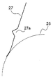
図5は、本発明の現像装置に用いられる規制部材の斜視図であり、図6は、規制部材が現像ローラに接触する様子を側面から見た拡大図である。図5に示すように、規制部材27には長手方向全域に亘って連続する断面V字状の溝部27aが形成されている。溝部27aの形成方法としては、板金製の規制部材27を折り曲げ加工する方法や、金型を用いてプレス加工する方法等が挙げられる。
FIG. 5 is a perspective view of a regulating member used in the developing device of the present invention, and FIG. 6 is an enlarged view of the manner in which the regulating member contacts the developing roller as viewed from the side. As shown in FIG. 5, the regulating
この構成とすることにより、溝部27aがリブの役割を果たすために規制部材27が長手方向へ撓みにくくなって規制部材27の平面度が高くなる。その結果、図6のように現像ローラ25表面へ微小圧力で接触させたとき均一な荷重が得られ、現像ローラ25上の長手方向において均一な厚みのトナー薄層を形成可能となる。特に、現像ローラ25への突き出し代(規制部材27の幅方向寸法)に余裕のない場合においても安定したトナー薄層が得られるため、図1に示したようなロータリープリンタに用いられる現像装置4a〜4d等の小型の現像装置に有効である。
By adopting this configuration, since the
また、規制部材27の先端に曲げ加工を施さないため、現像ローラ25の両端部においてトナー漏れを防止するシール部材30を、規制部材27の端部に密着させて配置することができる。従って、本発明の現像装置4aでは、現像ローラ25の長手方向における均一なトナー薄層の形成と、現像ローラ25の両端部におけるトナーシール性との両立が可能となり、本発明の現像装置が搭載された図1に示す画像形成装置100では、トナー薄層厚のばらつきに起因する画像濃度むらや現像ローラ25の軸受け部付近からのトナー漏れを効果的に抑制することができる。
In addition, since the tip of the regulating
なお、ここでは規制部材27を現像容器20に取り付けたとき現像ローラ25側が凹となるように溝部27aを形成しているが、現像ローラ25側が凸となるように溝部27aを形成することもできる。しかし、現像ローラ25側を凸とした場合は溝部27a内にトナーが滞留し易くなり、溝部27aを形成する位置によっては溝部27aと現像ローラ25とが干渉するおそれもある。従って、本実施形態のように現像ローラ25側が凹となるように溝部27aを形成することが好ましい。
Here, the
また、溝部27aを現像ローラ25との接触部分近傍に形成した場合は規制部材27の端部における平面性が損なわれ、トナー薄層の層厚にむらが生じるおそれがある。一方、溝部27aを規制部材取り付けステー33(図4参照)近傍に形成した場合は規制部材27の撓み防止効果が小さくなる。従って、規制部材の撓み防止効果とトナー薄層の均一化効果とをバランス良く得るためには、図5に示すように、規制部材27の側面の略中央部に溝部27aを形成することが好ましい。
Further, when the
また、溝部27aは必ずしも規制部材27の長手方向の全域に形成する必要はなく、溝部27aが長手方向の略全域に亘って形成されていれば、規制部材の撓み防止効果が期待できる。従って、例えば規制部材27の一端或いは両端にフラットな部分を残して溝部27aを形成しても良い。
In addition, the
その他本発明は、上記実施形態に限定されず、本発明の趣旨を逸脱しない範囲で種々の変更が可能である。例えば、溝部27aの断面形状はV字状に限らず、断面U字状、断面コ字状としても良い。また、本発明は図1に示したようなロータリー式のカラープリンタに限らず、デジタル或いはアナログ方式のモノクロ及びカラー複写機、ファクシミリ等、一成分現像方式の現像装置を備えた画像形成装置に適用可能である。
In addition, this invention is not limited to the said embodiment, A various change is possible in the range which does not deviate from the meaning of this invention. For example, the cross-sectional shape of the
本発明は、トナーを貯留する筐体と、該筐体内のトナーを担持するトナー担持体と、該トナー担持体に一端が圧接されトナー担持体上のトナー層厚を規制する規制部材と、を備えた一成分現像剤を用いる現像装置において、規制部材に、長手方向と略平行且つ長手方向の略全域に亘って連続する溝部を形成したものである。 The present invention includes a housing that stores toner, a toner carrier that carries the toner in the housing, and a regulating member that regulates the thickness of the toner layer on the toner carrier with one end pressed against the toner carrier. In the developing device using a single-component developer provided, a groove portion that is substantially parallel to the longitudinal direction and continuous over substantially the entire longitudinal direction is formed in the regulating member.
これにより、トナー担持体の長手方向におけるトナー薄層の均一性と、トナー担持体の両端部におけるトナーシール性とを両立可能な現像装置を簡便且つ低コストで提供することができる。 As a result, it is possible to provide a developing device that can achieve both the uniformity of the toner thin layer in the longitudinal direction of the toner carrier and the toner sealability at both ends of the toner carrier at a low cost.
また、規制部材の平面性に優れた本発明の現像装置を搭載することにより、長期間に亘って画像濃度むら等の画像不良やトナー漏れを生じない画像形成装置を提供することができる。 Further, by mounting the developing device of the present invention having excellent flatness of the regulating member, it is possible to provide an image forming apparatus that does not cause image defects such as image density unevenness or toner leakage over a long period of time.
1 感光体ドラム
4 現像ユニット
4a〜4d 現像装置
20 ハウジング(筐体)
21 トナー攪拌部
22 トナー供給部
24 攪拌パドル
25 現像ローラ(トナー担持体)
26 トナー供給ローラ
27 規制部材
27a 溝部
28 第1開口部
29 第2開口部
30 シール部材
31 開閉部材
33 規制部材取り付けステー
100 画像形成装置
DESCRIPTION OF
21
26
Claims (4)
該筐体内のトナーを担持するトナー担持体と、
該トナー担持体に一端が圧接され前記トナー担持体上のトナー層厚を規制する規制部材と、を備えた一成分現像剤を用いる現像装置において、
前記規制部材に、長手方向と略平行且つ長手方向の略全域に亘って連続する溝部と、該溝部の両側に折り線を介して連続する互いに略平行な一対の平坦部とが形成されており、前記溝部は、前記トナー担持体に対向する側が凹となるように形成されていることを特徴とする現像装置。 A housing for storing toner;
A toner carrier for carrying toner in the housing;
In a developing device using a one-component developer, comprising a regulating member having one end pressed against the toner carrier and regulating a toner layer thickness on the toner carrier,
The restriction member is formed with a groove portion that is substantially parallel to the longitudinal direction and continuous over substantially the entire length direction, and a pair of flat portions that are substantially parallel to each other via folding lines on both sides of the groove portion. The developing device is characterized in that the groove is formed so as to be concave on the side facing the toner carrier .
Priority Applications (3)
| Application Number | Priority Date | Filing Date | Title |
|---|---|---|---|
| JP2007277715A JP5210595B2 (en) | 2007-10-25 | 2007-10-25 | Developing device and image forming apparatus including the same |
| CN200810148877XA CN101419416B (en) | 2007-10-25 | 2008-10-07 | Developing device and image forming device with the same |
| US12/285,630 US8135317B2 (en) | 2007-10-25 | 2008-10-09 | Development device and image forming apparatus having same |
Applications Claiming Priority (1)
| Application Number | Priority Date | Filing Date | Title |
|---|---|---|---|
| JP2007277715A JP5210595B2 (en) | 2007-10-25 | 2007-10-25 | Developing device and image forming apparatus including the same |
Publications (2)
| Publication Number | Publication Date |
|---|---|
| JP2009104057A JP2009104057A (en) | 2009-05-14 |
| JP5210595B2 true JP5210595B2 (en) | 2013-06-12 |
Family
ID=40583018
Family Applications (1)
| Application Number | Title | Priority Date | Filing Date |
|---|---|---|---|
| JP2007277715A Expired - Fee Related JP5210595B2 (en) | 2007-10-25 | 2007-10-25 | Developing device and image forming apparatus including the same |
Country Status (3)
| Country | Link |
|---|---|
| US (1) | US8135317B2 (en) |
| JP (1) | JP5210595B2 (en) |
| CN (1) | CN101419416B (en) |
Families Citing this family (3)
| Publication number | Priority date | Publication date | Assignee | Title |
|---|---|---|---|---|
| KR20090104263A (en) * | 2008-03-31 | 2009-10-06 | 삼성전자주식회사 | Image forming apparatus and developer thereof |
| JP6261280B2 (en) * | 2013-08-09 | 2018-01-17 | キヤノン株式会社 | Development device |
| CN104516237B (en) * | 2013-09-27 | 2019-06-28 | 京瓷办公信息系统株式会社 | Toner container and image forming apparatus |
Family Cites Families (8)
| Publication number | Priority date | Publication date | Assignee | Title |
|---|---|---|---|---|
| JPH07134485A (en) | 1993-11-12 | 1995-05-23 | Nec Corp | Developing device |
| JPH08129301A (en) * | 1994-10-31 | 1996-05-21 | Sanyo Electric Co Ltd | Developing device |
| JPH08179624A (en) | 1994-12-27 | 1996-07-12 | Nec Corp | Developing device |
| JPH1010862A (en) * | 1996-06-21 | 1998-01-16 | Seiko Epson Corp | Developing device |
| JP4310091B2 (en) | 2002-09-30 | 2009-08-05 | キヤノン株式会社 | Developing cartridge and process cartridge |
| JP4372108B2 (en) | 2006-02-02 | 2009-11-25 | シャープ株式会社 | Developing device and image forming apparatus |
| KR20080023601A (en) * | 2006-09-11 | 2008-03-14 | 삼성전자주식회사 | A developer regulation device and a developing unit having the same |
| KR100863709B1 (en) * | 2006-11-22 | 2008-10-16 | 삼성전자주식회사 | Developing unit and image forming apparatus using the same |
-
2007
- 2007-10-25 JP JP2007277715A patent/JP5210595B2/en not_active Expired - Fee Related
-
2008
- 2008-10-07 CN CN200810148877XA patent/CN101419416B/en not_active Expired - Fee Related
- 2008-10-09 US US12/285,630 patent/US8135317B2/en not_active Expired - Fee Related
Also Published As
| Publication number | Publication date |
|---|---|
| US8135317B2 (en) | 2012-03-13 |
| JP2009104057A (en) | 2009-05-14 |
| US20090110446A1 (en) | 2009-04-30 |
| CN101419416B (en) | 2011-07-27 |
| CN101419416A (en) | 2009-04-29 |
Similar Documents
| Publication | Publication Date | Title |
|---|---|---|
| JP2014112140A (en) | Sealing mechanism, developing device, process unit, and image forming apparatus | |
| US6185392B1 (en) | Developing apparatus | |
| JP5210595B2 (en) | Developing device and image forming apparatus including the same | |
| JP5476695B2 (en) | Developing device, process cartridge, and image forming apparatus | |
| US20120045254A1 (en) | Developer regulator, development device, and image forming apparatus incorporating same | |
| JP2008111998A (en) | Developing device and image forming apparatus having the same | |
| EP2942671B1 (en) | Developing unit, image forming unit, and image forming apparatus | |
| US11556078B2 (en) | Developing device and image forming apparatus including same | |
| JP5244376B2 (en) | Developing device and image forming apparatus including the same | |
| US11550238B2 (en) | Developing device and image forming apparatus including same | |
| US11487220B1 (en) | Developing device and image forming apparatus including ihe same | |
| JP6019923B2 (en) | Powder conveying device, developing device, process cartridge, and image forming apparatus | |
| JP6112298B2 (en) | Developing device, process unit, and image forming apparatus | |
| JP7353885B2 (en) | Developing device, cartridge, image forming device | |
| JP2006154001A (en) | Developing device, and process cartridge and image forming apparatus equipped with this developing device | |
| JP6183528B2 (en) | Powder conveying device, developing device, process cartridge, and image forming apparatus | |
| JP2022168976A (en) | Developing device and image forming apparatus including the same | |
| US9500988B2 (en) | Developing apparatus | |
| JP2022168973A (en) | Developing device and image forming apparatus including the same | |
| JP2008216636A (en) | Developing device and image forming apparatus equipped therewith | |
| JP5332385B2 (en) | Developing device, process cartridge, and image forming apparatus | |
| JP4926693B2 (en) | Developing device, developing unit, image forming apparatus | |
| JP4870009B2 (en) | Developing device, process cartridge, and image forming apparatus | |
| JP2009210670A (en) | Developing device and image forming device | |
| JP2007079322A (en) | Developing device, process cartridge and image forming apparatus having the same |
Legal Events
| Date | Code | Title | Description |
|---|---|---|---|
| A621 | Written request for application examination |
Free format text: JAPANESE INTERMEDIATE CODE: A621 Effective date: 20100927 |
|
| A977 | Report on retrieval |
Free format text: JAPANESE INTERMEDIATE CODE: A971007 Effective date: 20120523 |
|
| A131 | Notification of reasons for refusal |
Free format text: JAPANESE INTERMEDIATE CODE: A131 Effective date: 20120529 |
|
| A521 | Request for written amendment filed |
Free format text: JAPANESE INTERMEDIATE CODE: A523 Effective date: 20120704 |
|
| TRDD | Decision of grant or rejection written | ||
| A01 | Written decision to grant a patent or to grant a registration (utility model) |
Free format text: JAPANESE INTERMEDIATE CODE: A01 Effective date: 20130129 |
|
| A61 | First payment of annual fees (during grant procedure) |
Free format text: JAPANESE INTERMEDIATE CODE: A61 Effective date: 20130225 |
|
| FPAY | Renewal fee payment (event date is renewal date of database) |
Free format text: PAYMENT UNTIL: 20160301 Year of fee payment: 3 |
|
| R150 | Certificate of patent or registration of utility model |
Ref document number: 5210595 Country of ref document: JP Free format text: JAPANESE INTERMEDIATE CODE: R150 Free format text: JAPANESE INTERMEDIATE CODE: R150 |
|
| RD03 | Notification of appointment of power of attorney |
Free format text: JAPANESE INTERMEDIATE CODE: R3D03 |
|
| LAPS | Cancellation because of no payment of annual fees |