EP4553548A2 - Verfahren und vorrichtung zur bildgebung mit multimodalen glasfasern - Google Patents
Verfahren und vorrichtung zur bildgebung mit multimodalen glasfasern Download PDFInfo
- Publication number
- EP4553548A2 EP4553548A2 EP25167464.4A EP25167464A EP4553548A2 EP 4553548 A2 EP4553548 A2 EP 4553548A2 EP 25167464 A EP25167464 A EP 25167464A EP 4553548 A2 EP4553548 A2 EP 4553548A2
- Authority
- EP
- European Patent Office
- Prior art keywords
- light
- fiber
- multimode waveguide
- multimode
- waveguide
- Prior art date
- Legal status (The legal status is an assumption and is not a legal conclusion. Google has not performed a legal analysis and makes no representation as to the accuracy of the status listed.)
- Pending
Links
Images


Classifications
-
- H—ELECTRICITY
- H04—ELECTRIC COMMUNICATION TECHNIQUE
- H04N—PICTORIAL COMMUNICATION, e.g. TELEVISION
- H04N1/00—Scanning, transmission or reproduction of documents or the like, e.g. facsimile transmission; Details thereof
- H04N1/40—Picture signal circuits
-
- G—PHYSICS
- G01—MEASURING; TESTING
- G01J—MEASUREMENT OF INTENSITY, VELOCITY, SPECTRAL CONTENT, POLARISATION, PHASE OR PULSE CHARACTERISTICS OF INFRARED, VISIBLE OR ULTRAVIOLET LIGHT; COLORIMETRY; RADIATION PYROMETRY
- G01J3/00—Spectrometry; Spectrophotometry; Monochromators; Measuring colours
- G01J3/02—Details
- G01J3/0205—Optical elements not provided otherwise, e.g. optical manifolds, diffusers, windows
- G01J3/0218—Optical elements not provided otherwise, e.g. optical manifolds, diffusers, windows using optical fibers
-
- G—PHYSICS
- G01—MEASURING; TESTING
- G01J—MEASUREMENT OF INTENSITY, VELOCITY, SPECTRAL CONTENT, POLARISATION, PHASE OR PULSE CHARACTERISTICS OF INFRARED, VISIBLE OR ULTRAVIOLET LIGHT; COLORIMETRY; RADIATION PYROMETRY
- G01J3/00—Spectrometry; Spectrophotometry; Monochromators; Measuring colours
- G01J3/28—Investigating the spectrum
- G01J3/44—Raman spectrometry; Scattering spectrometry ; Fluorescence spectrometry
-
- G—PHYSICS
- G02—OPTICS
- G02B—OPTICAL ELEMENTS, SYSTEMS OR APPARATUS
- G02B23/00—Telescopes, e.g. binoculars; Periscopes; Instruments for viewing the inside of hollow bodies; Viewfinders; Optical aiming or sighting devices
- G02B23/24—Instruments or systems for viewing the inside of hollow bodies, e.g. fibrescopes
- G02B23/26—Instruments or systems for viewing the inside of hollow bodies, e.g. fibrescopes using light guides
-
- G—PHYSICS
- G02—OPTICS
- G02B—OPTICAL ELEMENTS, SYSTEMS OR APPARATUS
- G02B26/00—Optical devices or arrangements for the control of light using movable or deformable optical elements
- G02B26/06—Optical devices or arrangements for the control of light using movable or deformable optical elements for controlling the phase of light
-
- G—PHYSICS
- G02—OPTICS
- G02B—OPTICAL ELEMENTS, SYSTEMS OR APPARATUS
- G02B27/00—Optical systems or apparatus not provided for by any of the groups G02B1/00 - G02B26/00, G02B30/00
- G02B27/58—Optics for apodization or superresolution; Optical synthetic aperture systems
-
- G—PHYSICS
- G02—OPTICS
- G02B—OPTICAL ELEMENTS, SYSTEMS OR APPARATUS
- G02B6/00—Light guides; Structural details of arrangements comprising light guides and other optical elements, e.g. couplings
- G02B6/02—Optical fibres with cladding with or without a coating
- G02B6/028—Optical fibres with cladding with or without a coating with core or cladding having graded refractive index
- G02B6/0288—Multimode fibre, e.g. graded index core for compensating modal dispersion
-
- G—PHYSICS
- G02—OPTICS
- G02F—OPTICAL DEVICES OR ARRANGEMENTS FOR THE CONTROL OF LIGHT BY MODIFICATION OF THE OPTICAL PROPERTIES OF THE MEDIA OF THE ELEMENTS INVOLVED THEREIN; NON-LINEAR OPTICS; FREQUENCY-CHANGING OF LIGHT; OPTICAL LOGIC ELEMENTS; OPTICAL ANALOGUE/DIGITAL CONVERTERS
- G02F1/00—Devices or arrangements for the control of the intensity, colour, phase, polarisation or direction of light arriving from an independent light source, e.g. switching, gating or modulating; Non-linear optics
- G02F1/01—Devices or arrangements for the control of the intensity, colour, phase, polarisation or direction of light arriving from an independent light source, e.g. switching, gating or modulating; Non-linear optics for the control of the intensity, phase, polarisation or colour
- G02F1/011—Devices or arrangements for the control of the intensity, colour, phase, polarisation or direction of light arriving from an independent light source, e.g. switching, gating or modulating; Non-linear optics for the control of the intensity, phase, polarisation or colour in optical waveguides, not otherwise provided for in this subclass
-
- G—PHYSICS
- G02—OPTICS
- G02F—OPTICAL DEVICES OR ARRANGEMENTS FOR THE CONTROL OF LIGHT BY MODIFICATION OF THE OPTICAL PROPERTIES OF THE MEDIA OF THE ELEMENTS INVOLVED THEREIN; NON-LINEAR OPTICS; FREQUENCY-CHANGING OF LIGHT; OPTICAL LOGIC ELEMENTS; OPTICAL ANALOGUE/DIGITAL CONVERTERS
- G02F1/00—Devices or arrangements for the control of the intensity, colour, phase, polarisation or direction of light arriving from an independent light source, e.g. switching, gating or modulating; Non-linear optics
- G02F1/01—Devices or arrangements for the control of the intensity, colour, phase, polarisation or direction of light arriving from an independent light source, e.g. switching, gating or modulating; Non-linear optics for the control of the intensity, phase, polarisation or colour
- G02F1/0136—Devices or arrangements for the control of the intensity, colour, phase, polarisation or direction of light arriving from an independent light source, e.g. switching, gating or modulating; Non-linear optics for the control of the intensity, phase, polarisation or colour for the control of polarisation, e.g. state of polarisation [SOP] control, polarisation scrambling, TE-TM mode conversion or separation
-
- G—PHYSICS
- G02—OPTICS
- G02F—OPTICAL DEVICES OR ARRANGEMENTS FOR THE CONTROL OF LIGHT BY MODIFICATION OF THE OPTICAL PROPERTIES OF THE MEDIA OF THE ELEMENTS INVOLVED THEREIN; NON-LINEAR OPTICS; FREQUENCY-CHANGING OF LIGHT; OPTICAL LOGIC ELEMENTS; OPTICAL ANALOGUE/DIGITAL CONVERTERS
- G02F1/00—Devices or arrangements for the control of the intensity, colour, phase, polarisation or direction of light arriving from an independent light source, e.g. switching, gating or modulating; Non-linear optics
- G02F1/29—Devices or arrangements for the control of the intensity, colour, phase, polarisation or direction of light arriving from an independent light source, e.g. switching, gating or modulating; Non-linear optics for the control of the position or the direction of light beams, i.e. deflection
- G02F1/31—Digital deflection, i.e. optical switching
- G02F1/313—Digital deflection, i.e. optical switching in an optical waveguide structure
-
- G—PHYSICS
- G03—PHOTOGRAPHY; CINEMATOGRAPHY; ANALOGOUS TECHNIQUES USING WAVES OTHER THAN OPTICAL WAVES; ELECTROGRAPHY; HOLOGRAPHY
- G03H—HOLOGRAPHIC PROCESSES OR APPARATUS
- G03H1/00—Holographic processes or apparatus using light, infrared or ultraviolet waves for obtaining holograms or for obtaining an image from them; Details peculiar thereto
- G03H1/0005—Adaptation of holography to specific applications
-
- G—PHYSICS
- G03—PHOTOGRAPHY; CINEMATOGRAPHY; ANALOGOUS TECHNIQUES USING WAVES OTHER THAN OPTICAL WAVES; ELECTROGRAPHY; HOLOGRAPHY
- G03H—HOLOGRAPHIC PROCESSES OR APPARATUS
- G03H1/00—Holographic processes or apparatus using light, infrared or ultraviolet waves for obtaining holograms or for obtaining an image from them; Details peculiar thereto
- G03H1/22—Processes or apparatus for obtaining an optical image from holograms
- G03H1/2286—Particular reconstruction light ; Beam properties
-
- G—PHYSICS
- G03—PHOTOGRAPHY; CINEMATOGRAPHY; ANALOGOUS TECHNIQUES USING WAVES OTHER THAN OPTICAL WAVES; ELECTROGRAPHY; HOLOGRAPHY
- G03H—HOLOGRAPHIC PROCESSES OR APPARATUS
- G03H1/00—Holographic processes or apparatus using light, infrared or ultraviolet waves for obtaining holograms or for obtaining an image from them; Details peculiar thereto
- G03H1/22—Processes or apparatus for obtaining an optical image from holograms
- G03H1/2294—Addressing the hologram to an active spatial light modulator
-
- H—ELECTRICITY
- H04—ELECTRIC COMMUNICATION TECHNIQUE
- H04B—TRANSMISSION
- H04B10/00—Transmission systems employing electromagnetic waves other than radio-waves, e.g. infrared, visible or ultraviolet light, or employing corpuscular radiation, e.g. quantum communication
- H04B10/25—Arrangements specific to fibre transmission
- H04B10/2581—Multimode transmission
-
- A—HUMAN NECESSITIES
- A61—MEDICAL OR VETERINARY SCIENCE; HYGIENE
- A61B—DIAGNOSIS; SURGERY; IDENTIFICATION
- A61B1/00—Instruments for performing medical examinations of the interior of cavities or tubes of the body by visual or photographical inspection, e.g. endoscopes; Illuminating arrangements therefor
- A61B1/06—Instruments for performing medical examinations of the interior of cavities or tubes of the body by visual or photographical inspection, e.g. endoscopes; Illuminating arrangements therefor with illuminating arrangements
- A61B1/07—Instruments for performing medical examinations of the interior of cavities or tubes of the body by visual or photographical inspection, e.g. endoscopes; Illuminating arrangements therefor with illuminating arrangements using light-conductive means, e.g. optical fibres
-
- G—PHYSICS
- G03—PHOTOGRAPHY; CINEMATOGRAPHY; ANALOGOUS TECHNIQUES USING WAVES OTHER THAN OPTICAL WAVES; ELECTROGRAPHY; HOLOGRAPHY
- G03H—HOLOGRAPHIC PROCESSES OR APPARATUS
- G03H1/00—Holographic processes or apparatus using light, infrared or ultraviolet waves for obtaining holograms or for obtaining an image from them; Details peculiar thereto
- G03H1/04—Processes or apparatus for producing holograms
- G03H1/0402—Recording geometries or arrangements
- G03H2001/0434—In situ recording when the hologram is recorded within the device used for reconstruction
-
- G—PHYSICS
- G03—PHOTOGRAPHY; CINEMATOGRAPHY; ANALOGOUS TECHNIQUES USING WAVES OTHER THAN OPTICAL WAVES; ELECTROGRAPHY; HOLOGRAPHY
- G03H—HOLOGRAPHIC PROCESSES OR APPARATUS
- G03H1/00—Holographic processes or apparatus using light, infrared or ultraviolet waves for obtaining holograms or for obtaining an image from them; Details peculiar thereto
- G03H1/04—Processes or apparatus for producing holograms
- G03H1/0443—Digital holography, i.e. recording holograms with digital recording means
- G03H2001/0447—In-line recording arrangement
Definitions
- the present invention relates to producing high-resolution images through a multimode fiber such as but not limited to endoscopic imaging.
- Embodiments of the present invention relate generally to imaging through multimode fibers, and in particular, to methods and apparatus for imaging through a multimode fiber.
- the illumination is delivered via a multimode fiber core and the optical information backscattered by a sample is collected and carried optically through the same said multimode fiber core prior to conversion to a digital image.
- the digital image is formed by first converting the optical signal to an electronic signal by a single or multi-element photodetector and then by processing the said electronic signal.
- the multimode fiber imaging system may be passive, i.e., contain no active elements at the distal end of the multimode fiber or alternatively it may contain actuators/sensors at the distal end for certain uses.
- the formation of a digital image is achieved by:
- the backscattered optical signal can be, but is not limited to, single or two photon fluorescence signal and/or Raman signal and/or linear backscattering intensity generated from a sample.
- Super-resolution i.e., resolution below the diffraction limit, is achieved for example but not limited to, using the STimulated Emission Depletion microscopy (STED) technique or the Structured Illumination Microscopy (SIM) technique in combination with the MM fiber imaging method.
- Optical endoscopes are shown to be devices of increasing interest for the investigation of the human body.
- State of the art endoscopes can be classified into two categories: widefield endoscopes based on fiber bundles or GRIN lenses and scanning based systems using single mode optical fibers. In both cases, these systems are limited either by their size, flexibility, imaging resolution or their weak light collection.
- Most endoscopic systems are adapted from commonly used free space microscopy techniques where the image contrast can be generated in different ways.
- An image can be, for example, obtained by collecting light scattered by a sample where the changes in the optical refraction index gives structural information.
- This linear scattering imaging can be improved by applying a specific illumination (as in bright-field or dark-field imaging).
- Biological structures can also naturally emit light by fluorescence when they absorb a probe light.
- auto-fluorescence signal an image can be constructed.
- Artificial fluorescent markers can also be added to the sample for targeting a specific structure and obtain functional information about that structure. The fluorescence signal, emitted by these markers after excitation, can be collected to form what is called an optical fluorescence image.
- Optical fluorescence imaging relies on a sample (dyed or not) emitting a fluorescence signal after light excitation. An image is obtained by collecting the fluorescence emission, which is usually at a longer wavelength than the excitation, either through a wide field microscope or a scanning optical microscope.
- the fluorescence image is directly collected and formed through the optical system.
- the endoscopic equivalent relies on the use of either a short (mm scale) small diameter GRIN lens as a microscope objective or fiber bundles, which consists of fibers arranged in an array. In the latter, the resolution is limited by the inter-core spacing.
- Scanning optical microscopes are based on producing an image point by point by scanning a diffraction limited focus spot.
- the optical information which can be either a linear signal (scattering, single fluorescence) or a non-linear signal, is collected to form an image.
- the detected light resulting from one illuminated volume element represents one pixel in the resulting image.
- the beam is scanned across the sample in two dimensions or in three dimensions (axially).
- a pinhole can be added to form a confocal arrangement.
- the illumination/excitation beam first passes through an aperture and then is focused on the sample.
- the detection apparatus has a pinhole that obstructs the light that is not coming from the focal point.
- the out-of-focus light is rejected leading to a sharper image and giving the possibility to perform optical sectioning by acquiring images at various depths.
- a confocal arrangement can be made with GRIN-lens endoscopes but not with a fiber bundle.
- two-photon imaging or multi-photon imaging
- Raman imaging excitation is based on the effect that two photons of comparably lower energy than needed for one photon excitation, can also excite a fluorophore in one quantum event. Each photon carries approximately half the energy necessary to excite the molecule. An excitation results in the subsequent emission of a fluorescence photon. Since the probability of simultaneous absorption of two photons is extremely low, a concentrated flux of photons is necessary, a condition experimentally realized at the focus of a high numerical objective and using femtosecond pulsed laser sources.
- Two-photon imaging systems typically require fluorophores tagged to a specimen of interest in order to obtain strong two-photon efficiency.
- GRIN-lens endoscopes and fiber bundles have been demonstrated to provide dispersion compensation to maintain a short pulse duration at the sample.
- Raman imaging uses the Raman effect which is an inelastic scattering effect in which a probe photon (from a probe beam) interacts with the vibrational levels of the probed molecules.
- the resulting scattered photon is energy-shifted by an amount equal to the energy of the vibrational level involved.
- Raman scattering is weak (typ. 1 ppm) and thus a high number of photons per volume is needed to produce a Raman shifted photon. This condition is experimentally realized at the focal spot of a lens. Continuous wave laser beams are typically used.
- An enhancement of the Raman signal is realized by a nano-patterned surface (metal) on which the probed molecules reside. The electric field at specific spots on the nano-patterned surface is enhanced by a plasmonic effect (electron resonance effect with the light frequency).
- SERS surface enhanced Raman scattering
- a better resolution can be achieved if one uses a so-called "super-resolution" imaging microscopy technique.
- Two major techniques are used that both rely on a patterned illumination: STimulated Emission Depletion microscopy (STED) which is a scanning based method and Structured Illumination Microscopy (SIM), which is a wide-field method.
- STED (stimulated emission depletion) microscopy makes use of non-linear de-excitation of fluorophores to overcome the Abbe diffraction limit and was proposed by Hell and co-workers ( US 5,731,588 , 7,064,824 , 7,430,045 ).
- a structure is tagged with a substance such as a fluorophore that can be in either of two states having each a specific optical property.
- the state of the substance can be toggled between the first and second state and vice-versa by means of a switch-over optical signal.
- the light induced toggling between the two states is non-linear with light intensity.
- a first excitation beam is focused by a high numerical aperture objective lens on the sample tagged with the fluorophores to bring the latter to an excited state.
- a second beam, red-shifted to the first optical beam is focused by the same objective to form a doughnut beam at its focus.
- the red-shifted beam toggles the fluorophores to a second state by a stimulated depletion effect.
- the doughnut beam has zero intensity only at the center and thus fluorophores, located within an area smaller than the diffraction limit around the center, remain in the first state.
- Fluorophores in the first state emit a fluorescence radiation that is collected by the same high numerical objective and separated by color filters from the first and second excitation/de-excitation beams respectively.
- the Gaussian and doughnut spot size are scanned together, e.g., by a system of rotating mirrors placed before the high numerical objective.
- SIM microscopy is, unlike STED microscopy, a wide-field technique that can improve the resolution of a fluorescence light microscope by at least a factor of two ( US 6,239,909 ; US 2012/0026311 ).
- SIM uses a grid to create several interference patterns on the sample.
- the illumination pattern interacts with the fluorescent probes in the sample to generate interference patterns known as moiré fringes that include high-resolution information that is normally inaccessible.
- moiré patterns are superimposed upon each other to form a single image. This can be done by using widefield microscopy and placing a fine mesh grating in the light path before excitation.
- the resolution limit is defined by the optical transfer function, which is the normalized Fourier transform of the point-spread function. When two frequencies are mixed (the multiplication of two signal), moiré fringes are created. When moiré patterns are combined, information outside of the conventionally observable space becomes observable.
- microscopy techniques mentioned above rely on free-space optical components such as high numerical aperture microscope objectives and can be adapted, in a more or less straightforward way, to an endoscopic device.
- Scanning-based endoscopic devices usually rely on the use of a single-mode fiber for the focused excitation and a second fiber, usually multimode, for light collection.
- GRIN rigid lenses are used or bundles of large number of single-mode fibers are used, even if they have an inherent resolution limitation coming from the inter core spacing.
- a narrow bandpass filter is placed in the path of the collimated beam to block the Raman signal and to transmit only the probe beam.
- a high pass filter then reflects the probe beam.
- a second lens focuses the probe beam onto the sample.
- a notch filter is placed behind the high pass filter to block the Rayleigh scattered probe beam while transmitting the frequency shifted Raman signal.
- the Raman signal is then focused in a multimode fiber for collection.
- the diameter of the fiber probe is thus of the order of 10 mm to accommodate the free-space collimating lenses and filters.
- ⁇ is the wavelength of the light
- NA is the numerical aperture of the multimode fiber
- ⁇ is the fiber core diameter
- dispersion effects are also very important in multimode fibers resulting in a temporal spreading of an input light pulse. These two aspects have always limited their use for light transmission, and particularly for fiber-based imaging.
- Light scrambling occurring in multimode fibers produce speckle patterns that are similar to light patterns created as a result of propagation in a diffuse medium.
- a digital phase conjugation technique has been applied to a bundle of near single mode fibers to coherently combine the output of 3 fibers: C. Bellanger, A. Brignon, J. Colineau, and J. P. Huignard, "Coherent fiber combining by digital holography," Opt. Lett., OL 33, 2937, 2008 .
- the invention provides a method for deterministic light transmission through a multimode waveguide comprising the steps of: providing the multimode waveguide; a distal tip having a distal end facet and a proximal tip at an opposed end of the multimode waveguide; calibrating the multimode waveguide, whereby the calibrating comprises: coupling in light at an input side of the multimode waveguide for at least one polarization state; analyzing light coupled in at an input side of the multimode waveguide at an output side of the multimode waveguide.
- the method for deterministic light transmission further comprises conditioning the input of the multimode waveguide by controlling a spatial light modulator for at least one polarization state to choose an appropri-ate light field at the output of the multimode waveguide.
- the step of calibrating is realized through transmission matrix measurement.
- the method further comprises adjusting a focal spot at the output side of the multimode waveguide by digitally controlling the spatial light modulator in the conditioning step, directing the focal spot exiting the output side of the multimode waveguide to a sample, and illuminating the sample by scanning the focal spot on the sample.
- the method further comprises steps of: directing light to a sample; analyzing scrambled light collected through the multimode waveguide from the sample to recover an image; analyzing light collected from the sample; and constructing an image of the sample in three dimensions, corresponding to different depths in the sample.
- the method further comprises steps of providing light pulses, at the step of coupling in light; and providing short light pulses at the output side of the multimode waveguide by applying an appropriate light field at the step of conditioning the wave-guide when controlling the spatial light modulator.
- the method further comprises steps of determining a wavelength required for excitation of the sample; and choosing a wavelength equal to twice the said wavelength required for excita-tion of the sample for the light at the step of providing light pulses.
- the method further comprises collecting through the multimode fiber nonlinear signals emanating from the sample such as Raman, two photon, and second harmonic of the input light.
- the method further comprises steps of placing a scattering medium at the output side of the multimode waveguide to decrease the size of the focal spot on the sample.
- the multimode waveguide is a flexible waveguide, the method further comprising inserting part of the multimode wave-guide in a sample and moving the multimode waveguide while adapting the conditioning pattern in the step of conditioning the input.
- the method further comprises achieving super-resolution by projecting determined spatial patterns at the step of conditioning the waveguide, and by exciting the sample with a first wavelength and depleting with a second wavelength with a determined ring pattern.
- the method further comprises achieving super-resolution by stochastically illuminating the sample when directing light from the output side of the waveguide.
- the method further comprises controlling the polarization of light at the output side of the multimode wave-guide; analyzing light coupled in at the input side of the waveguide, at an output side for at least one polarizations state; and conditioning the output of the multimode waveguide for at least one polarization state.
- the multimode waveguide is an optical waveguide that presents modal scrambling and high dispersion, wherein the multimode waveguide is at least one of the items in the following list:
- the invention provides a system for deterministic light transmission through a multimode waveguide.
- the system comprises the multimode waveguide, calibrating means configured for calibrating the multimode waveguide, the calibrating means comprising light coupling means for coupling light at an input side of the multi-mode waveguide for at least one polarization state, analyzing means arranged for analyzing light at an output side of the multimode waveguide, the analyzing means comprising a digital analyzing system that digitally analyzes a complex light field in its phase or amplitude properties, and the system for deterministic light transmission further comprising conditioning means configured to condition the output of the multi-mode waveguide, the conditioning means comprising a spatial light modulator configured to choose the appropriate light field for at least one polarization state 1 at the input tip of the multimode waveguide.
- the multimode waveguide is an optical waveguide, wherein the multimode waveguide is one of items in the following list:
- the spatial light modulator is one of items of the following list:
- the conditioning means are further config-ured to adjust a focal spot at the output side of the multimode waveguide by digital control of the spatial light modulator.
- the system further comprises directing means configured to direct the focal spot exiting the output side of the multimode waveguide to a sample, and scanning means configured to illuminate the sample by scanning the focal spot on the sample.
- system further comprises a spectrometer, and directing means configured to direct Raman light arriving from the sample to the spectrometer.
- system further comprises collecting through the multimode fiber nonlinear signals emanating from the sample such as Raman, two photon, and second harmonics.
- the system further comprises beacon means configured to calibrate the multimode waveguide from the same side as the input side in real-time, the beacon means comprising a beacon light source arranged such that light from the beacon light source is coupled by light coupling means, and analyzing means at the input side of the multimode waveguide for recording the light pattern generated by the beacon light source after propagating through the multimode waveguide.
- system further comprises means configured to compare the analyzed light pattern with a database of light patterns corresponding to different configurations of the multimode waveguide.
- the multimode waveguide is a flexible waveguide, the system further adapting the conditioning pattern in the step of conditioning the input in response to changes in the flexible waveguide.
- the excitation means are provided by one of a co-propagating single mode fiber, a plurality of co-propagating single mode fibers, and a co-propagating single mode core in a double-clad multimode waveguide.
- multimode fibers comprises any multimode wave-guide element.
- the lensless multimode fiber based imaging system and apparatus allows for several embodiments including 1) a system for delivering a sequence of complex illumination patterns such as, but not limited to a diffraction limited spot at the distal end of a MM fiber and/or 2) a system for collecting scattered light and constructing an image through a multimode fiber and/or 3) a system for performing non-linear imaging through a multimode fiber such as but not limited to, Raman and two photon and/or 4) a system to achieve super-resolution imaging through a multimode fiber based on a specific illumination pattern and/or 5) a system that allows for the control of the field of view, working distance and resolution.
- the present invention relates to a system and method for deterministic light transmission through a multimode fiber.
- the system first contains a multimode fiber including, but not limited to, step-index fiber, graded index fiber, double-clad fiber, large mode area fiber, fiber bundles, any optical waveguide that presents modal scrambling and high dispersion and no-core fibers such as but not limited to rods.
- the multimode fiber is calibrated, i.e. that light coupled in at one side of the fiber is analyzed at the output of the fiber, which can be the opposite end of the fiber or it can be the same side that light was coupled in.
- This calibration is based on a system that digitally analyzes the complex light field (phase and amplitude) including, but not limited to, a coherent holographic system and/or an incoherent system for which phase and amplitude is recovered via a method such as, but not limited to Transport of Intensity (TIE) for wavefront analysis.
- Calibration methods include, but are not limited to, digital phase conjugation, transmission matrix measurement and iterative wavefront control.
- the modulation of the input field is performed with a spatial light modulator (SLM) such as, but not limited to, phase liquid crystal SLMs, deformable mirrors, binary or analog amplitude modulators.
- SLM spatial light modulator
- the system conditions the output of the multimode fiber by choosing the appropriate light field at the proximal tip of the multimode fiber by way of a spatial light modulator.
- the output pattern includes, but is not limited to, a diffraction limited focus spot. Aberrations, modal scrambling and dispersion are compensated for, so that the spatial properties of the light at the distal end of the fiber are controlled.
- the system allows for scanning a diffraction-limited spot at the distal end of the fiber by sending the appropriate light fields at the proximal end. Focusing at the fiber tip does not require a lens and scanning the focal spot does not require mechanical actuators, rather this is obtained purely by digital control of the spatial light modulator.
- the portion of the endoscope from the proximal end to the distal end is passive i.e. does not contain active elements such as electrical or magnetic actuator. In this embodiment the endoscope is digitally controlled to provide a scanning lensless endoscope.
- the system allows for light collection with the same multimode fiber.
- multimode fibers present large light gathering capabilities due to their large core and numerical aperture.
- the multimode fiber is used for signal collection whereby, for each scanned position of a sample the signal is collected.
- the beam is scanned point by point at the distal end of the multimode fiber.
- Light collected for one scanning position represents one pixel in the resulting image.
- the image is constructed pixel by pixel.
- the number of scanning points gives the number of pixels in the image and the lateral image resolution is given by the maximum of the distance between two neighboring scanning points and the focal spot size.
- light collected from the fiber is generated by, but not limited to, linear scattering, single fluorescence of the sample or of a dye attached to a specific structure of the sample or a non-linear signal generated by coherent or non coherent processes such as but not limited to second harmonic generation and multi-photon excitation respectively.
- the system comprises then a dichroic beam splitter allowing for the separation of the excitation light injected at the proximal end of the fiber and the fluorescence light collected through the fiber, which is at longer wavelength.
- a specific filter should be used in front of the detector in order to reject the background signal generated at the excitation wavelength.
- light collected from the fiber is directed, via an appropriate beam splitter to a Raman spectrometer.
- the Raman spectrum is then measured with, but not limited to, a dispersive monochromator or a Fourier based interferometer. Since spontaneous Raman scattering is weak ( ⁇ 1 ppm), high selectivity filters need to be used in order to separate the inelastically scattered light from the intense Rayleigh scattered laser light.
- the Raman signal collection combined with the scanning capability of the system allow for the construction of Raman images with chemical specificity. Because the probe beam is delivered by a large core multimode fiber, the non-linear signal, such as but not limited to Raman, generated by the fiber itself can be neglected compared to the non-linear signal produced by the sample under test at the focal point.
- Sapphire fibers have low fluorescence and Raman scattering compared with silica fibers and are preferred as such.
- One or more multimode fibers, surrounding the multimode fiber bringing the probe beam are also disclosed to collect the Raman signal.
- the multimode fiber bringing the probe beam is also the collecting fiber for the non-linear signal such as but not limited to Raman.
- the invention allows for axial depth sectioning in an image.
- a database of speckle patterns is recorded corresponding to an ensemble of scattered point sources distributed in the field of view of the multimode fiber.
- a 3-dimensional sample is illuminated through the output of the multimode fiber, which can be for example, but not limited to, a plane wave.
- the resulting scattered speckle image is captured and correlated with the speckle patterns of the database.
- a 3-dimensional image is then constructed by assigning the value of the correlation for each spatial location of the known reference patterns.
- temporal pulse shaping in order to deliver short light pulses through the fiber.
- This temporal pulse shaping can be a separate apparatus combined with the above-mentioned wavefront shaping system or only one system allowing for both temporally and spatially shaping the beam.
- the ability to control light propagation through a multimode fiber both in space and time enables illuminating the sample with a short pulse in the desired spatial pattern, including but not limited to a single focus spot or a doughnut beam.
- a temporally short light pulse spatially focused will generate a non-linear signal in the sample, such as but not limited to a two photon signal.
- the excitation wavelength is twice the wavelength of the two photon signal, and by choosing the excitation to lie in the so-called therapeutic window (approximately 600-800 nm), the penetration depth is increased in the sample and enables a better out-of-plane light rejection.
- the resolution of the endoscope system is increased by placing a scattering medium at the distal end of the multimode fiber, which has for effect to increase the effective numerical aperture of the fiber. Propagation of light through this scattering medium is controlled in the same way as in the fiber: the ensemble multi-mode fiber and scattering medium constituting the new complex medium through which light is spatially and temporally controlled.
- a potential difficulty arising from the suggested geometry is the fact that the scattering phenomena both during focusing and also during light collection for imaging are going to decrease the expected photon budget. This can be overcome by just increasing the power of the excitation laser source or by using a less scattering medium.
- a different approach could be to use a notch filter with an annular scattering ring in a dark-field configuration. This approach will exploit the annular ring for the generation of the focused spot and on the collection part; most of the fluorescent light will propagate backwards unaffected into the fiber.
- the wavefront shaping system allows for a controlled patterned illumination of a sample.
- the system By choosing the right phase pattern to project at the proximal end of the multimode fiber, the system generates a specific light pattern at the distal end, including but not limited to, a doughnut shaped beam, or a sinusoidal light illumination, or Hadamard matrix based illumination.
- the calibration method allows also for image recovery from the scrambled light collected at the proximal end of the multimode fiber. This capability allows for wide field imaging through the multimode fiber where the image is reconstructed from the speckle.
- a calibration of the fiber can be provided from one side of the fiber by partially reflecting the speckle field at the distal end of the multimode fiber and by changing the incidence angle of the reference beam.
- SIM structured illumination microscopy
- super solution imaging is achieved by illuminating the sample with different light patterns that incorporate higher spatial frequencies.
- the sample is illuminated with different patterns from the multimode waveguide. The signal reflected by the sample is transmitted back through the multimode waveguide and unscrambled thanks to the image recovery embodiment described above.
- Another embodiment discloses a super-resolution imaging capability based on stochastic illumination as in PALM (Photo Activated Localization Microscopy) or STORM (Stochastic Optical Reconstruction Microscopy). Based on the image recovery ability described above, advantage can be taken from a stochastic illumination to extract, from the image transmitted through the multimode waveguide, the position of each single emitter in a sample. The iteration of the process allows constructing a super-resolution image.
- PALM Photo Activated Localization Microscopy
- STORM Stochastic Optical Reconstruction Microscopy
- beacon beam providing a reference virtual focal point source at the distal end of the MM fiber.
- the conformation of the fiber modifies the distribution of the modes inside the MM fiber, but does not modify the reference virtual point source.
- this virtual point source provides a reference that is used to continuously calibrate the system i.e the distribution of modes.
- this beacon beam serves as a sensing beam because the scrambled light pattern generated by this beam at the proximal end gives information about the fiber conformation, for example but not limited to a bending configuration.
- the beacon source is a real optical source such as a point source of light, or a specified light pattern that can be excited in transmission or reflection. This includes, but is not limited to, a generated focus spot, a generated optical pattern, multiple foci spots, coherent emitters, a reflection or scattering from a surface, an image.
- one or many single mode fibers co-propagates with the multimode fiber to illuminate an optical element near the tip of the multimode fiber to produce one or more virtual beacon beams, Gaussian or/and doughnut shaped but not limited to them.
- the optical element includes but is not limited to a lens, a hologram or a prism.
- the said phase pattern is then fed to the beam shaping apparatus that provides the appropriate pattern at the proximal end of the multimode fiber so as to generate after propagation, the desired illumination, for example, but not limited to, a focused beam.
- a set of interference patterns obtained as described above for different fiber bending configurations is stored into a database.
- the bending configuration can be inferred by matching the interference pattern generated by the beacon with the patterns stored in a database.
- the system can achieve a real-time wavefront compensation of modal scrambling in the multimode fiber.
- an array of beacons, as described above, each corresponding to a fiber in a fiber bundle is disclosed.
- the size of the focus spot, the distance from the fiber tip and also the number of focus spots can be controlled allowing for a lensless fiber endoscope with a flexible resolution, field of view and working distance. All these parameters are limited by the optical properties of the fiber or the complex medium (if the multimode fiber is combined to a scattering medium for higher resolution).
- a scattering element is created on the surface of the multimode fiber core to couple light out to the side of the fiber. This allows for creating patterns along and around the side of the fiber thus expanding the field of view of the endoscope.
- a scattering rod is fused to the core of the multi-mode fiber.
- structures inside the multimode fiber such as but not limited to slanted gratings, deflect light to the side of the fiber.
- the present invention discloses means and methods to transmit high speed digital information in a multimode fiber.
- the input output relationship is known and thus an array of two dimensional optical sources (data) can be mapped onto a 2-dimensional array of detectors at the distal end of the fiber.
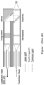
- Fig. 1 (State of the Art) is a drawing of a Raman probe.
- a small lens collimates the beam and a transmission narrowband filter blocks the Raman signal and transmits the probe beam.
- a high pass filter reflects the probe beam, which is then focused on the sample under test by a second lens.
- a notch filter placed behind the high pass filter blocks the Rayleigh scattered probe beam.
- the filtered Raman signal is then focused in a multimode fiber for collection.
- the diameter of the fiber probe is thus of the order of 10 mm to accommodate the free space collimating lenses and filters.
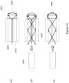
- Fig. 2 describes the principle of STED (Stimulated Emission Depletion) microscopy.
- a first excitation beam is focused by a high numerical aperture objective lens on the sample tagged with the fluorophores to bring the latter to an excited state.
- a second beam, red-shifted, is focused by the same objective to form a doughnut beam.
- the red-shifted beam toggles the fluorophores to a second state by a stimulated depletion effect.
- the doughnut beam has zero intensity only at the center and thus fluorophores, located within an area smaller than the diffraction limit around the center, remain in the first state.
- Fluorophores in the first state emit a fluorescence radiation that is collected by the same high numerical objective and separated by color filters from the first and second excitation/de-excitation beams respectively.
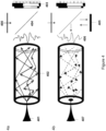
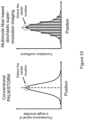
- Fig. 3 describes the principle of resolution enhancement by structured illumination.
- Fig. 3a is an example of two superimposed sinusoidal illumination patterns creating a Moiré pattern.
- Fig. 3b shows the region in frequency space that is observable by conventional microscopy.
- Fig. 3c shows that each sinusoidal illumination pattern has three frequency components: one at the origin representing the average intensity, and two at ⁇ k1, representing the modulation.
- Fig. 3d shows the observable region for conventional microscopy in the center and the extended region due to structured illumination. Centered on ⁇ k1, a new set of information becomes visible.
- Fig. 3e shows the corresponding observable regions if the procedure is repeated with other pattern orientations. The much larger region of observable spatial frequencies (e) compared with that shown in (b) makes it possible to reconstruct the sample with correspondingly increased spatial resolution.
- Fig. 4 shows the principles of focusing through a multimode fiber by digital phase conjugation.
- a first calibration step fig. 4a
- a focused calibration beam 401 is injected at one end of the multimode fiber 402.
- the beam coming out the other end of the multimode fiber 402 is combined, via beam-splitter 404, with a coherent reference beam 400 with a small angle.
- the resulting off-axis interferogram is recorded on a two dimensional detector 403.
- the phase extracted form the said off-axis interferogram is displayed onto spatial light modulator 405.
- Reference beam 400 is incident and diffracted by said spatial light modulator 405.
- the diffracted beam 406 is reflected by beam-splitter 404 and backward propagated through the fiber 402. A tightly focused spot 407 is then observed at the distal end of the fiber.
- the beam-splitter 404 can be a thick volume reflection holographic filter that transmits the reference beam 400 and reflects the diffracted beam 406 because the angle of the diffracted beam is Bragg matched.
- a thick reflection holographic filter (millimeters) is known to be highly angularly selective, although efficient at the Bragg matching angle (see J. Goodman "introduction to Fourier Optics", Wiley ).
- Beam-splitter 404 can also be a narrow band thin film interference filter or any filter with a high angular selectivity.
- the experimental set-up for the implementation of digital phase conjugation through a multimode fiber is shown in fig. 5 .
- the calibration point source is obtained by focusing beam 500 with a high numerical aperture microscope objective 501.
- the calibration point source displayed as a dot on the lower right in image 502, is injected in the multimode fiber 503 at its distal end.
- the facet at the other end of the fiber is imaged via objective 504 and lens 505 on image sensor 506.
- a reference beam 507 is combined with the output beam of the fiber by beams-splitter 508.
- An off-axis interferogram of the two beams, also called hologram is recorded by the image sensor 506.
- the recorded hologram is then treated numerically and the phase of the optical field on the output facet of the fiber is retrieved.
- phase conjugated beam The calculated phase pattern 509 is then displayed onto spatial light modulator 510.
- the conjugate optical field that is generated in this way is reflected back into the imaging line by beam-splitter 508 and projected onto the multi-mode fiber facet.
- the conjugated field propagates backward through the multimode optical fiber 503 and is focused at the distal end of the fiber, recreating point source 502.
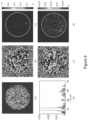
- Fig. 6 (a) to (f) shows experimental images illustrating focusing through a multimode fiber using digital phase conjugation.
- Fig. 6 (a) is a speckle pattern at the output of the fiber as a result of a point source excitation launched at the multimode fiber input.
- Fig. 6 (b) is the calculated phase from the interferogram (not shown).
- Fig. 6 (c) is the phase conjugated focus point at the input of the fiber. The focus is created at exactly the same position as the excitation.
- Fig. 3 (e) , (f) show the result when a random phase pattern is assigned to the SLM and its corresponding image at the output of the fiber. Clearly no focusing effect can be observed.
- Fig. 6 (a) is a speckle pattern at the output of the fiber as a result of a point source excitation launched at the multimode fiber input.
- Fig. 6 (b) is the calculated phase from the interferogram (not shown).
- Fig. 6 (c) is the phase
- FIG. 3 (d) shows the profile of the phase-conjugated spot along the red dashed line drawn in Fig. 3 (c) and Fig. 3 (f). Without the phase conjugation the field appears as random speckles.
- the white circle in Fig. 3 (c) and Fig. 3 (f) defines the multimode fiber core.
- Fig. 7 illustrates digital scanning of a focal spot at the distal end of the multi-mode fiber 704.
- the phase patterns corresponding to each point source 700 and 701 at the distal end of the fiber are digitally stored and sequentially displayed onto the spatial light modulator 702 which is readout by reference beam 703 to produce the required phase conjugated beam.
- This system generates optical scanning of a focus spot at the distal end of the multimode fiber 704 without any mechanical actuation.
- Fig. 8 shows overlaid images of ⁇ 1000 focused spots generated 200 ⁇ m away from the multimode fiber tip.
- the scanning region has a diameter of 60 ⁇ m, the spots have a waist of 1.4 ⁇ m and the pitch of the regular grid is 1.5 ⁇ m.
- Each spot is generated alone at the field of view and has a constrast > 2000 with respect to the background.
- the scanning speed of the system is limited by the SLM refresh rate of 60Hz. Scale bar equal to 10 ⁇ m.
- the refresh speed can reach up to 23 kHz (Texas Instrument DLP), hence decreasing the scan time from 16 seconds to 43 milliseconds for 33 x 33 pixels image or from 2 minutes 40 seconds to 0.43 seconds for 100 x 100 pixels image.
- Fig. 9 describes the collection capabilities of a multimode fiber.
- a fluorescent sample 900 is excited by a focus spot (excitation spot) generated via the multimode fiber by the endoscopic system described above, the fluorescence signal 901 is collected back through the same fiber and collected on the detector 903.
- a dichroic filter 902 blocks the linearly scattered light by the said excitation spot and transmits the red-shifted fluorescent light.
- An image is formed by sequentially scanning the excitation spot in the field of view of the multimode fiber and detecting the fluorescent light.
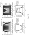
- Fig. 10 shows the resolution and fluorescence collection efficiency of the fiber endoscope as a function of working distance z and the distance from the optical axis of the system x as calculated using a geometrical optics analysis. The calculations are done, by way of example but not limited to, using a 220 ⁇ m fiber core diameter, 0.53 NA and visible light.
- the resolving power of the imaging system becomes worse as the imaging plane is set away from the fiber tip while at the same time, the useful field of view increases.
- the figures indicate a clear trade off between resolution and field of view.
- Fig 10 (b), (d) present the fluorescence collection efficiency of the imaging system as a function of position. The efficiency is worse as the fluorophore is placed away from the fiber facet and towards the edges of the field of view.
- the simulations can help us predict the behavior of the system and correct any differences in the fluorescent levels of the final image.
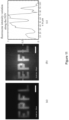
- Fig. 11 shows the large field of view accessible with the multimode fiber scanning fluorescence imaging apparatus described above.
- the wide-field fluorescence image of a fluorescent pattern "EPFL" on a glass slide prepared with photolithography is shown in figure 11 (a).
- Fig. 11 (b) is the scanning fluorescent image obtained with the fiber endoscope described above at a working distance of 200 ⁇ m.
- the difference in the fluorescence level between the center and the edges is attributed to the different collections efficiencies away from the optical axis of the fiber and the quasi linear dependence observed coincides with the predicted behavior for the specific working distance.
- the endoscope is capable of providing high information capacity, large field of view images. Scale bar equal to 20 ⁇ m.
- Fig. 12 demonstrates the high-resolution capability of the multimode fiber endoscope by providing a comparison with a conventional wide-field optical system of the same numerical aperture and estimated resolution.
- Fig. 12 (a) shows a wide field image obtained with a 0.5 NA microscope objective and fig. 12 (d) shows the same sample obtained with the multimode fiber.
- the information conveyed by the lensless multi-mode fiber endoscope is directly comparable to that given by the 0.5 NA microscope objective.
- the comparison of the cross sectional plots (b),(e) and (c),(f) verifies the conclusion.
- Fig. 12 (g) and (h) are used to estimate the resolution of the system. In Fig.
- the bead sample is imaged with a 0.65 NA objective to obtain a more detailed view.
- the multimode scanning fiber system (with a pixel pitch of 0.5um) gives an image in which the two beads, almost fused into each other, can be still be resolved. Therefore, the resolution limit of the system is in the submicron range. Scale bars in all images are 10 ⁇ m.
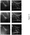
- Fig. 13 shows images of the cellular and subcellular structure of neurons obtained with the multimode fiber endoscope described above. Images of fluorescently stained neuronal cells acquired with the multimode fiber endoscope are compared with conventional wide-field images acquired with a microscope objective.
- the first column in fig. 13 (a) shows a wide-field fluorescent image of a single neuron soma and fig. 13 (d) shows details of dendrites.
- the middle row in fig. 13 (b) and (e) shows the raw fluorescent image acquired with the fiber endoscope and fig. 13 (c) and (f) show resampled and filtered images 13 (b) and (e), so that the pixelation induced by the scanning acquisition is smoothed.
- Highly detailed images of the neuronal soma and the dendritic network can be resolved by the multimode fiber imaging system.
- the high quality of the images can make this endoscope useful for diagnostic purposes based on cellular phenotype.
- the working distance is 200 ⁇ m to compensate for the coverslip that separates the cells from the fiber facet.
- Field of view is 60 ⁇ m by 60 ⁇ m and scale bars in all images are 10 ⁇ m.
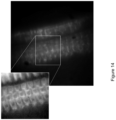
- Fig. 14 shows images of a fluorescently stained pig's cochlear hair cell obtained through the round window with the multimode fiber endoscope described above. The three rows of hair cells can be clearly seen. This demonstrates the capability of the multimode endoscope to image features of the cochlea. The small size of multimode endoscope makes it suitable to image the cochlear in-vivo in humans for diagnostic purposes.
- Fig. 15 shows a concept to obtain axial depth sectioning in an image.
- a two-dimensional sensor 1506 captures the speckle patterns 1504 and 1505. Patterns 1504 and 1506 correspond to linearly scattered light from point sources 1501 and 1502 respectively after propagation in the multimode waveguide element 1503.
- a database 1507 of speckle patterns is recorded corresponding to an ensemble of scattered point sources distributed in the field of view of the multimode fiber.
- a 3-dimensional sample is illuminated through the output of the multimode fiber 1503 which can be for example, but not limited to, a plane wave.
- the resulting scattered speckle image is captured by the 2-D sensor 1506. This image is then correlated with the speckle patterns of the database.
- a 3-dimensional image is then constructed by assigning the value of the correlation for each spatial location of the known reference patterns.
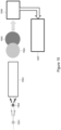
- Fig. 16 shows a concept to achieve both spatial focusing and temporal focusing at the output of a multimode fiber.
- a transform limited ultra-fast pulse 1600 is temporally stretched with a suitable pulse stretcher 1610 which can be static or dynamic (SLM) to generate pulse 1620 which is then spatially modulated by a spatial light modulator 1630.
- the modulated wavefront is then incident on a diffuse medium 1640.
- the scattered light is focused onto a multimode waveguide element 1635, such as a fiber, but not limited to.
- the temporal and spatial properties are entangled and by a suitable input wavefront distribution, a temporally and spatially focused spot 1660 is generated.
- Fig. 17 shows a system using a multimode fiber-based Raman probe.
- the system consists of a Raman laser source 1700 incident on a beam splitter 1710.
- the beam-splitter 1710 can be a free-space beam-splitter or a fiber-based beam-splitter.
- the Raman laser light is split into a beacon single mode fiber reference 1715 and the beam 1720 is used for Raman excitation.
- the beacon fiber 1715 is either located on the side of the multimode fiber 1725 ( fig.17 (a), (b) ) or inside the multimode fiber 1725, such as for example a double clad fiber ( fig. 17 (c) ).
- Fig. 17 (a) shows optical element 1722 reflecting the reference beam 1715 into the multimode fiber 1725.
- Optical element 1722 can be a holographic element producing a virtual point source or a reflective surface producing the same.
- Fig. 17 (b) shows optical element 1726 on which facet a reflective point source is deposited to reflect the beacon beam 1715 into the multi-mode fiber 1725.
- Fig. 17 (c) shows optical element 1728 that reflects the beacon beam into multimode fiber 1725.
- Element 1728 can be either a holographic element, a reflective curved surface or a scattered point source deposited on the facet of element 1728.
- the reference beacon 1715 propagates from the distal end of the multimode fiber 1725 to it proximal end.
- a microscope objective 1765 and lens 1750 images the output facet of the multimode fiber 1725 onto a 2-D camera 1740.
- the beamsplitter 1735 combines the speckled beacon beam coming out of the proximal end of the multimode fiber 1725 with the Raman excitation beam 1720 to form an off-axis interferogram. As is described in the invention above, the amplitude and phase of the said speckle beacon beam is calculated.
- the phase pattern is then displayed on the spatial light modulator 1730 to produce a phase-conjugated beam that propagates backward to the distal end of the multimode fiber 1725 to form a tight focus spot.
- the Raman signal generated a the said tight focal spot is collected by the same multimode fiber 1725.
- a dichroic filter 1736 directs the Raman signal towards a spectrometer 1745, which generates a Raman spectrum on the camera 1746. Notch filters or edge filters for excitation light rejection and are placed in the path of the Raman beam after the dichroic filter 1736 and before the spectrometer 1745.
- a 2-dimensional Raman image can be constructed by digitally scanning the focal point as is described in the patent above.
- the choice for the multimode fiber 1725 should be selected from fibers that exhibit a small Raman signal.
- a Sapphire fiber is preferred.
- standard silica based fiber can also be used because the intensity in the core of a multi-mode fiber of 100 micrometers diameter is approximately 10,000 smaller than the intensity at the focal spot at the distal end of the multimode fiber. Hence the Raman signal from the fiber itself is negligible compared to the Raman signal from the sample located at the focus.
- Fig. 18 shows another system using a multimode fiber-based Raman probe.
- the difference with the system in fig. 17 is the collection multimode fibers 1880 surrounding the multimode fiber 1860 bringing the Raman excitation light.
- the reference beacon single mode fiber 1870 is used for providing a reference speckle interferogram identical to the system in fig. 18 . Since the collection fibers 1880 are separate from the excitation fiber 1860, the former are directly connected to a set of notch filters or edge filters 1885 to remove the excitation light prior to entering spectrometer 1890 and camera 1895.
- Fig. 19 shows the concept for increasing the lateral resolution of the multimode fiber endoscope.
- the concept is also applicable to any multimode waveguide element.
- a scattering medium 1905 is placed at a distance to the distal end of the multimode fiber 1910. The larger the said distance is the higher is the lateral resolution.
- a point source 1900 is first sent through the scattering medium before being coupled in the multimode fiber 1910.
- a phase conjugation system 1920 described above in the present patent generates a phase-conjugated beam 1925 that reproduces the point source 1900. Because the scattering effectively increase the numerical aperture of the fiber, the spot size is smaller hence the resolution is higher.
- Fig. 20 (a)-(d) describes a system for providing super-resolution STED through a multimode waveguide element.
- a first excitation beam 2000 and a second depletion beam 2005 are both split in two by beam-splitter 2010. Beam 2000 and 2005 are independently controlled.
- a fraction of beam 2000 and 2005 are coupled into single mode fiber 2015 for use as a beacon reference.
- the other fraction of beam 2000 and 2005 are directed towards beamsplitter 2020, which splits the beams into two parts.
- One part is directed to digital camera 2035 and the other part is incident on spatial light modulator 2040.
- the single mode fiber 2015 containing beams 2000 and 2005, which are of different wavelength is coupled to multimode fiber 2070 (via a coupler not shown).
- the single mode fiber 2015 becomes the single mode fiber of a double clad multimode fiber 2070 as shown in fig. 20 (b)-(c) .
- an element 2071 is attached to the distal end of the multimode fiber 2070.
- Element 2071 has a reflective lens or a holographic reflective film on its facet to produce a virtual point source 2072 (e.g. Gaussian) for the beam 2000 and a virtual doughnut beam 2073 for the beam 2005.
- the details of element 2071 are described in figs. 21-24 .
- a rigid multi-mode waveguide element 2070 is used. In this instance, the reference beacons 2015 may not be necessary, which simplifies the system.
- the focused Gaussian beam 2072 is generated by focusing a collimated Gaussian beam with a high numerical aperture microscope objective (not shown, including immersion objectives).
- the doughnut beam 2073 is generated by introducing a phase plate (not shown) in the path of a collimated Gaussian beam and focusing it with a high numerical aperture microscope objective (not shown).
- phase-conjugated beams corresponding to the point source 2072 and doughnut beam 2073 are generated at the distal end of the fiber ( fig. 20 (c) ).
- the super-resolved fluorescence spot 2074 is the result of the illumination of the excitation Gaussian spot size followed by the depletion doughnut-shaped beam. This said fluorescence is then collected by the same multimode fiber 2070 and directed to a detector 2050 by a dichroic filter 2030.
- An experimental image of the doughnut-shaped beam is shown in fig. 20 (d) .
- Fig. 21 shows the concept for axially translating a focal spot at the distal tip of a multimode waveguide endoscope. It is well known that the azimuthal angle of a cone of light 2100 is preserved after propagation through a multimode circularly symmetric waveguide 2110 (U. Levy, A. Friesem Appl. Phys. Lett. 32, 29 (1978)). The output cone 2120 retains the same angle as the input cone 2100. This equality means that the propagation vector k in the direction of propagation z remains unchanged. In the digital phase conjugation system applied to multimode waveguides described in this patent, one can use this effect to change the axial location of the focal point generated at the distal end of a multimode waveguide. Fig.
- a spatial light modulator 2130 provides a phase-conjugated beam 2150 to focus light 2170 at the distal end of multimode waveguide 2110.
- a spatial light modulator 2130 provides a quadratic phase profile to the phase pattern using the same spatial light modulator 2130 or equivalently by using an additional electronically adjustable focal length lens 2140, the location of the focal spot 2170 is moved axially to focal spot location 2180.
- Fig. 22 is a description of a virtual holographic beacon guided digital phase conjugation process through a double-clad fiber.
- the light in the single mode fiber 2200 of the multimode double clad fiber 2210 interferes coherently, in reflection, with light originating from a point source 2230.
- the interference occurs on a holographic material 2220.
- the holographic material can be, but not limited to, a polymer, a photorefractive crystal, a photorefractive glass.
- the point source 2230 can be generated by a high a NA object or a multi-spot light pattern (not shown).
- the point source is located in such a way that it is coupled in the double cladding on the dual clad multimode fiber 2210.
- Fig. 22b shows the recorded holographic element 2220 illuminated by the output light from the single mode fiber 2200.
- Element 2220 produces diffracted light 2240, which recreates the wavefront originating from the virtual point source 2230.
- the diffraction efficiency of the holographic element is such that it allows an appropriate detection signal on the camera in system 2250. Diffraction efficiency values of a few percent to few ten percent are suggested.
- the diffracted light 2240 propagates to the proximal end of multimode fiber 2210 and whose phase and amplitude is recovered by system 2250 (described above in the patent).
- the phase-conjugated beam is then generated by system 2250.
- a real focus point 2260 is then generated ( fig 22c ).
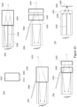
- Fig. 23 describes other implementations of beacon generation.
- a partially reflective micro-lens is described.
- a reflective layer 2320 is on the surface of a concave (or convex) element 2300.
- Element 2310 protects said reflective layer 2320 and whose index of refraction should be chosen close to that the refractive index of element 2300.
- the reflective micro-lens may not need protective element 2310 to be functional.
- the reflective layer 2320 is partially reflective. It may comprise metallic coatings, dielectric coatings or any other type of reflective coating with any spectral bandpass, broad or narrow.
- Fig. 23b shows said reflective micro-lens array 2340 attached to a multimode flexible double clad fiber 2360.
- the output light from single mode core 2350 illuminates the micro-lens 2340 to produce reflected light that is coupled in the double cladding od multimode fiber 2360.
- the reflective surface of micro-lens 2340 is designed in such a way that the reflected light originates from a virtual focus 2330.
- Fig. 23c is a variation of fig. 23b where the single mode fiber 2365 is not inside the multimode fiber 2360 but is located outside. Similarly to fig. 23b , the output light from the single mode fiber 2365 generates a virtual focus 2370 by reflection off the partially reflective layer of the micro-lens.
- the reflective element 2385 is a holographic element (as described in fig.
- Fig. 23e shows a variation of fig. 23d where the illumination side is from the top facet of element 2387.
- Fig. 23f shows a lens element 2390 attached to a double clad multimode fiber 2360 so as to form an image of the output of the single mode fiber 2350 onto a reference surface 2393 (for example, but not limited to, the surface of a microscope slide).
- the reflected light is then coupled in the multimode fiber 2360.
- the reference speckle pattern at the proximal end of the multimode fiber serves as a reference.
- the reference is used to sense the conformation of the flexible multimode fiber so as to use the appropriate set of phase pattern to the spatial light modulator as described in the patent.
- Fig. 24 shows an image of a fabricated reflected micro-lens described in fig. 23 .
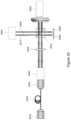
- Fig. 25 describes a polarization preserving wavefront shaping system that improves the signal to noise ratio of the generated pattern at the output of a multimode waveguide element. This system treats both polarizations separately.
- a light beam produces two orthogonal polarization beams 2505 (s-polarization) and 2510 (p-polarization) using a polarizing beam-splitter 2500.
- a non-polarizing beam-splitter 2515 splits the beams in two directions. One direction is directed towards a 2D camera 2520 and records one interferogram for each polarization, with the light output from a multimode fiber 2530.
- the phase pattern corresponding to the s-polarization component is displayed on one side of the spatial light modulator 2550 and the p-polarization component is displayed on the other side 2560.
- the single spatial light modulator can be replaced by two spatial light modulators, one for each polarization.
- a wave-plate can be added on one of the reference beams or on one side of the spatial light modulator.
- Fig. 26 shows a schematic of a flexible multimode fiber endoscope system with the distal end of the multimode fiber 2600 embedded into a rigid needle 2640.
- the rigid needle 2640 shown has an opening at its end.
- the rigid needle 2640 may have an opening on the side (not shown) in which case the distal end of the multimode fiber has an element (not shown) such as, but not limited to, a right angle prism to direct light to the said opening for side looking.
- the system of fig. 26 is composed of a digital phase conjugation sub-system (such as described above in this patent), which is controlled by a computer 2620.
- the digital phase conjugation device has an optical fiber input to deliver one or more wavelength of light to the multimode fiber endoscope.
- the multimode fiber 2600 can be embedded in a larger tube (not shown), which may contain a camera for guidance (not shown) and other illumination means.
- the multimode fiber endoscope is then pointed to a specific location by the user to obtain high-resolution images.
- the digital imaging capability of the multimode fiber is used both as a guiding mean by using the digital focusing capability described for example in figs. 4 , 5 , 7 , 10 and 21 (low resolution, large depth) and as a high resolution instrument.
- the various imaging modalities such as, but not limited to, super-resolution, side viewing, total internal reflection, two photon, Raman described in this patent are all applicable to this system.
- the outer diameter of the endoscope is limited only by the needle and can be as small as 460um for a 250um cladding fiber for example.
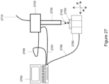
- Fig. 27 shows a digital microscope system using a rigid multimode waveguide as the imaging component.
- a computer 2700 controls, via cables 2705, 2706, 2707, a digital phase conjugation sub-system (such as described above in this patent) 2720, up to three or more linear translation stages, rotation stages 2760 and one or more optical sources 2715.
- the imaging capability of the digital phase conjugation system 2720 described in this patent is used in conjunction with the set of stages 2760 to provide various magnification and resolution of the object under test 2750.
- the field of view and magnification are determined by the distance between the distal end of the multimode rigid waveguide element 2730 and the sample under test 2750.
- a coarse distance value maybe determined with sensors placed appropriately on the stages 2760 and waveguide element 2730.
- the digital 3-dimensional focusing ability of the sub-system allows a user to view a sample with a large field of view and resolution (large distance) and then select an area to zoom-in. By appropriately moving the stages 2760 and digitally refocusing at the appropriate axial distance, a finer resolution image is generated.
- the described system uses only one optical element (2730).
- a thin and long (needle like) multimode waveguide element 2730 can reach areas that are not accessible with standard microscope objectives or grin lens micro-objective, which are short.
- a suggested size for the multimode waveguide element is, but not limited to, 0.1-0.5 mm diameter by 5-20 cm long.
- a deployable "umbrella-like" mechanism in front of the multimode fiber can be used as an inserting and protecting device. It will open up to the final form after the fiber endoscope is inserted inside the area that is to be imaged and prevent the deposition of tissue debris while the endoscopic head is inserted in the body.
- imaging modalities such as, but not limited to, super-resolution, side viewing, total internal reflection, two photon, Raman described in this patent are all applicable to this system.
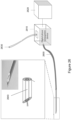
- Fig. 28 is shown to form a total internal reflection microendoscope.
- Figure 28a shows the calibration of the system.
- a plane wave 2800 is incident on a wedge prism 2805 whose index of refraction is approximately the same as the index of refraction of the core of the waveguide element 2810.
- the plane wave 2800 is coupled to the core of the waveguide element 2810.
- the output facet of 2810 is angled so as to allow the waveguided light to out-couple with low loss to form the output light field 2815.
- the amplitude and phase of light field 2815 is extracted by the coherent interferometric system 2820 described above.
- the phase-conjugated light field 2825 corresponding to the output light field 2815 is generated by a spatial light modulator (part of 2820 but not shown).
- the phase-conjugated field at the distal facet end 2835 of the waveguide element 2810 is a plane wave 2830.
- the wedge prism element 2805 has been removed.
- the angle of the plane wave 2830 and the normal to the facet 2835 is such that it satisfies the total internal reflection condition.
- the reflected beam 2840 propagates back in the waveguide element 2810.
- the evanescent wave at the interface (not shown) has a short penetration depth (several nanometers) and thus able to probe the interface of a sample located at the fiber tip.
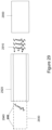
- Fig. 29 shows a side viewing high-resolution multimode waveguide endoscope.
- An element 2930 which has a diffuser on its surface, is attached to the distal end of a multimode waveguide element 2920.
- a point source 2940 is coupled to the core of the multimode waveguide element 2920 via the diffuser.
- the digital phase conjugation system 2900 generates a phase-conjugated wave 2910 that recreates the point source 2940. Because the lateral side of the diffuser element 2930 is large, hence the numerical aperture in this direction is larger than in the orthogonal direction (limited by the diameter of element 2930). Therefore the spot size has a high resolution in the direction of the length of element 2930. By mapping spots around element 2930 at least a two pi steradian field of view is obtained.
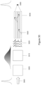
- Fig. 30 shows a system schematic to achieve short pulse delivery and high resolution at the distal end of a coherent fiber bundle.
- a short pulse 3000 (tens of femtoseconds to hundreds of femtoseconds) is incident on a pulse shaper 3005 that impart an amount of dispersion on the pulse.
- a spatial light modulator or a digital phase conjugation sub-system 3015 provides a phase-conjugated beam 3020 as described in the patent.
- the waveguide element 3030 is a fiber bundle of single mode fibers or multimode with a low number of modes ( ⁇ 10).
- a typical fiber bundle can have several thousands to tens of thousand fibers. Typical distance between fibers is 3 micrometers, however the distance can be several tens of micrometers.
- the waveform 3020 has a chromatic dispersion that is equal but with opposite sign to the dispersion of the single mode fibers 3030.
- the spatial phase modulation of beam 3020 is such that each fiber of the fiber bundle 3030 at the distal end acts as a phased array antenna that tightly focuses the beam at an axial distance 3040.
- the pulse is recompressed in time due to the opposite sign of dispersion of the single mode fibers.
- Fig. 31 shows a schematic for calibrating a multimode waveguide element from one side.
- a plane wave 3100 is incident on a spatial light modulator 3110 which can also be any device that deflects a beam such as, but not limited to, a rotatable mirror, an acousto-optic deflector, an electro-optic deflector.
- a plane wave 3120 is diffracted or deflected by element 3110 towards a beam-splitter 3130 that redirects the plane wave in the core of a multimode waveguide element 3140.
- the distal end facet 3150 of the multimode waveguide 3140 has a partially reflective layer or simply reflective by Fresnel reflection. The reflected wavefront gets scrambled twice through the multimode wave-guide 3140.
- the speckled output waveform 3160 is interfered with reference 3100. Phase and amplitude are recovered from the interferogram. The process is repeated with multiple angles imparted on the beam 3100. The transmission matrix of twice the propagation is then recovered. Because the return path follows the same waveguide element, the transmission matrix for single path is recovered.
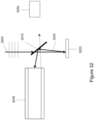
- Fig. 32 shows a system to efficiently couple a phase conjugated light beam in a multimode waveguide element.
- a plane wave beam 3200 is incident on a beam-splitter 3120 at an angle such that the beam-splitter transmits efficiently (>90%) beam 3200.
- the phase-conjugated beam 3230 is diffracted at a small angle, typically a few degrees only and is directed back to beam-splitter 3210.
- the angular selectivity of beam-splitter 3210 is such that it reflects efficiently (>80%) beam 3230 and directs it to the multi-mode waveguide element 3240.
- beam splitter 3210 is a thick reflection Bragg grating made from polymer or glass or crystal material. Thick reflection Bragg gratings are well known to be highly angularly selective. In another instance a reflective thin film filter, narrowband or edge is used with the appropriate angular selectivity.
- Fig. 33 shows the principle of super-resolution imaging based on a stochastic illumination.
Landscapes
- Physics & Mathematics (AREA)
- General Physics & Mathematics (AREA)
- Optics & Photonics (AREA)
- Nonlinear Science (AREA)
- Spectroscopy & Molecular Physics (AREA)
- Engineering & Computer Science (AREA)
- Signal Processing (AREA)
- Dispersion Chemistry (AREA)
- Chemical & Material Sciences (AREA)
- Astronomy & Astrophysics (AREA)
- Electromagnetism (AREA)
- Computer Networks & Wireless Communication (AREA)
- Multimedia (AREA)
- Investigating, Analyzing Materials By Fluorescence Or Luminescence (AREA)
- Optical Couplings Of Light Guides (AREA)
Applications Claiming Priority (3)
| Application Number | Priority Date | Filing Date | Title |
|---|---|---|---|
| IB2012051509 | 2012-03-29 | ||
| EP13722100.8A EP2831497B1 (de) | 2012-03-29 | 2013-03-28 | Verfahren und vorrichtung für bildgebung mit multimodalen glasfasern |
| PCT/IB2013/052493 WO2013144898A2 (en) | 2012-03-29 | 2013-03-28 | Methods and apparatus for imaging with multimode optical fibers |
Related Parent Applications (2)
| Application Number | Title | Priority Date | Filing Date |
|---|---|---|---|
| EP13722100.8A Division EP2831497B1 (de) | 2012-03-29 | 2013-03-28 | Verfahren und vorrichtung für bildgebung mit multimodalen glasfasern |
| EP13722100.8A Division-Into EP2831497B1 (de) | 2012-03-29 | 2013-03-28 | Verfahren und vorrichtung für bildgebung mit multimodalen glasfasern |
Publications (2)
| Publication Number | Publication Date |
|---|---|
| EP4553548A2 true EP4553548A2 (de) | 2025-05-14 |
| EP4553548A3 EP4553548A3 (de) | 2025-08-06 |
Family
ID=48428554
Family Applications (2)
| Application Number | Title | Priority Date | Filing Date |
|---|---|---|---|
| EP25167464.4A Pending EP4553548A3 (de) | 2012-03-29 | 2013-03-28 | Verfahren und vorrichtung zur bildgebung mit multimodalen glasfasern |
| EP13722100.8A Active EP2831497B1 (de) | 2012-03-29 | 2013-03-28 | Verfahren und vorrichtung für bildgebung mit multimodalen glasfasern |
Family Applications After (1)
| Application Number | Title | Priority Date | Filing Date |
|---|---|---|---|
| EP13722100.8A Active EP2831497B1 (de) | 2012-03-29 | 2013-03-28 | Verfahren und vorrichtung für bildgebung mit multimodalen glasfasern |
Country Status (3)
| Country | Link |
|---|---|
| US (1) | US9871948B2 (de) |
| EP (2) | EP4553548A3 (de) |
| WO (1) | WO2013144898A2 (de) |
Families Citing this family (106)
| Publication number | Priority date | Publication date | Assignee | Title |
|---|---|---|---|---|
| IL224301A0 (en) * | 2013-01-17 | 2013-06-27 | Rafael Advanced Defense Sys | New mode division multiplexing for an optical communication system |
| US20140235948A1 (en) * | 2013-02-19 | 2014-08-21 | The Board Of Trustees Of The Leland Stanford Junior University | Method for single-fiber microscopy using intensity-pattern sampling and optimization-based reconstruction |
| DE102013019347A1 (de) * | 2013-08-15 | 2015-02-19 | Carl Zeiss Microscopy Gmbh | Hochauflösende Scanning-Mikroskopie |
| GB201318598D0 (en) * | 2013-10-21 | 2013-12-04 | Univ Leicester | Improvements in or relating to super-resolution microscopy |
| WO2015112770A1 (en) | 2014-01-22 | 2015-07-30 | The Regents Of The University Of Colorado, A Body Corporate | Optical imaging devices and variable-focus lens elements, and methods for using them |
| EP3119264B1 (de) * | 2014-03-18 | 2020-04-22 | Steris Instrument Management Services, Inc. | Optisch adaptives endoskop |
| US10398294B2 (en) * | 2014-07-24 | 2019-09-03 | Z Square Ltd. | Illumination sources for multicore fiber endoscopes |
| DE102014113716B4 (de) * | 2014-09-23 | 2021-11-11 | Abberior Instruments Gmbh | Vorrichtung zum getrennten Modulieren der Wellenfronten von zwei Komponenten eines Lichtstrahls und Rasterfluoreszenzlichtmikroskop |
| JP6863896B2 (ja) * | 2014-09-29 | 2021-04-21 | マジック リープ,インコーポレイティド | 導波路から異なる波長の光を出力する構造および方法 |
| JP6484719B2 (ja) * | 2014-10-17 | 2019-03-13 | シー アーチン テクノロジーズ エルエルシー | レンズレス内視鏡および他の撮像デバイス |
| FR3030956B1 (fr) * | 2014-12-18 | 2018-03-23 | Centre National De La Recherche Scientifique - Cnrs | Dispositif de transport et de controle d'impulsions lumineuses pour l'imagerie endo-microscopique sans lentille |
| US10018817B2 (en) | 2015-03-04 | 2018-07-10 | Aramco Services Company | Adaptive optics for imaging through highly scattering media in oil reservoir applications |
| WO2016149416A1 (en) | 2015-03-16 | 2016-09-22 | Magic Leap, Inc. | Methods and systems for diagnosing and treating health ailments |
| KR101766328B1 (ko) * | 2015-05-28 | 2017-08-08 | 광주과학기술원 | 현미경 |
| KR101638016B1 (ko) * | 2015-05-28 | 2016-07-08 | 광주과학기술원 | 내시경 |
| IL295566B2 (en) | 2015-06-15 | 2024-01-01 | Magic Leap Inc | Display system with optical elements for in-coupling multiplexed light streams |
| WO2016207881A1 (en) * | 2015-06-23 | 2016-12-29 | Yeda Research And Development Co. Ltd. | Controlled optical focusing through flexible graded-index multimode fibers without distal end access |
| US10551019B2 (en) | 2015-08-24 | 2020-02-04 | Lumileds Holding B.V. | Illumination device for a vehicle headlight |
| US9696255B2 (en) * | 2015-10-16 | 2017-07-04 | National Central University | Image processing method of two-photon structured illumination point scanning microscopy |
| CN105352926B (zh) * | 2015-11-10 | 2018-11-16 | 深圳大学 | 一种随机扫描的系统 |
| US10254534B2 (en) * | 2015-11-30 | 2019-04-09 | The Regents Of The University Of Colorado, A Body Corporate | Single multimode fiber endoscope |
| DE102015121920A1 (de) * | 2015-12-16 | 2017-06-22 | Carl Zeiss Microscopy Gmbh | Hochauflösendes Kurzzeit-Mikroskopieverfahren und hochauflösendes Kurzzeit-Mikroskop |
| WO2017103643A1 (en) | 2015-12-17 | 2017-06-22 | Université D'aix-Marseille (Amu) | Systems and methods for high resolution imaging using a bundle of optical fibers |
| JP6670943B2 (ja) * | 2016-02-12 | 2020-03-25 | キヤノン ユーエスエイ, インコーポレイテッドCanon U.S.A., Inc | 前方ビューのスペクトル符号化内視鏡検査のための簡単なモノリシック光学素子 |
| FR3049135B1 (fr) * | 2016-03-15 | 2020-02-14 | Cailabs | Dispositf de communications par fibre optique multimode avec composant de compensation de dispersion modale |
| WO2017176898A1 (en) | 2016-04-08 | 2017-10-12 | Magic Leap, Inc. | Augmented reality systems and methods with variable focus lens elements |
| CN107317954A (zh) * | 2016-04-26 | 2017-11-03 | 深圳英伦科技股份有限公司 | 3d内窥胶囊镜检测方法和系统 |
| US9894254B2 (en) * | 2016-05-10 | 2018-02-13 | Massachusetts Institute Of Technology | Methods and apparatus for optical fiber imaging |
| WO2017197020A1 (en) | 2016-05-12 | 2017-11-16 | Magic Leap, Inc. | Distributed light manipulation over imaging waveguide |
| EP4300457A3 (de) | 2016-11-11 | 2024-03-13 | Carrier Corporation | Hochempfindliche glasfaserbasierte detektion |
| EP3539103A1 (de) | 2016-11-11 | 2019-09-18 | Carrier Corporation | Auf hochempfindlicher faseroptik basierende detektion |
| US11151853B2 (en) * | 2016-11-11 | 2021-10-19 | Carrier Corporation | High sensitivity fiber optic based detection |
| US11132883B2 (en) | 2016-11-11 | 2021-09-28 | Carrier Corporation | High sensitivity fiber optic based detection |
| WO2018089654A1 (en) | 2016-11-11 | 2018-05-17 | Carrier Corporation | High sensitivity fiber optic based detection |
| EP3542215B1 (de) | 2016-11-18 | 2022-11-02 | Magic Leap, Inc. | Räumlich variable flüssigkristallbeugungsgitter |
| US11067860B2 (en) | 2016-11-18 | 2021-07-20 | Magic Leap, Inc. | Liquid crystal diffractive devices with nano-scale pattern and methods of manufacturing the same |
| IL266677B2 (en) | 2016-11-18 | 2023-11-01 | Magic Leap Inc | A waveguide light multiplexer using crossed gratings |
| KR102639600B1 (ko) | 2016-11-18 | 2024-02-21 | 매직 립, 인코포레이티드 | 넓은 입사 각도 범위들의 광을 방향전환시키기 위한 다중층 액정 회절 격자들 |
| US10605984B2 (en) * | 2016-12-01 | 2020-03-31 | Waymo Llc | Array of waveguide diffusers for light detection using an aperture |
| EP3552057B1 (de) | 2016-12-08 | 2022-01-05 | Magic Leap, Inc. | Diffraktive vorrichtungen auf basis von cholesterischem flüssigkristall |
| CA3046328A1 (en) | 2016-12-14 | 2018-06-21 | Magic Leap, Inc. | Patterning of liquid crystals using soft-imprint replication of surface alignment patterns |
| US10371896B2 (en) | 2016-12-22 | 2019-08-06 | Magic Leap, Inc. | Color separation in planar waveguides using dichroic filters |
| CN106707523A (zh) * | 2017-01-19 | 2017-05-24 | 宁波纳美致生物科技有限公司 | 一种无机械应力多模光纤光束斑均匀化系统 |
| CN106842529B (zh) * | 2017-01-23 | 2019-03-01 | 清华大学 | 快速三维显微成像系统 |
| AU2018210527B2 (en) | 2017-01-23 | 2022-12-01 | Magic Leap, Inc. | Eyepiece for virtual, augmented, or mixed reality systems |
| US20190384006A1 (en) * | 2017-01-27 | 2019-12-19 | Vanderbilt University | Systems and methods for reduced end-face reflection back-coupling in fiber-optics |
| IL268630B2 (en) | 2017-02-23 | 2023-09-01 | Magic Leap Inc | Display system with variable power reflector |
| CN117075345A (zh) * | 2017-03-21 | 2023-11-17 | 奇跃公司 | 用于照射空间光调制器的方法、设备和系统 |
| KR102576133B1 (ko) | 2017-03-21 | 2023-09-07 | 매직 립, 인코포레이티드 | 회절 광학 엘리먼트들을 이용한 눈-이미징 장치 |
| EP3607382B1 (de) * | 2017-04-06 | 2025-07-30 | Konstantin Roggatz | Augmented-reality(ar)-brille und verfahren zur einmischung virtueller bilder in ein durch mindestens ein brillenglas für einen träger der brille sichtbares bild |
| CN106932916B (zh) * | 2017-05-04 | 2019-10-01 | 鲁东大学 | 一种利用超材料透镜的双光束超分辨聚焦方法 |
| IL273397B2 (en) | 2017-09-21 | 2024-09-01 | Magic Leap Inc | An augmented reality display with a waveguide configured to capture images of an eye and/or environment |
| KR102716968B1 (ko) | 2017-12-15 | 2024-10-11 | 매직 립, 인코포레이티드 | 증강 현실 디스플레이 시스템을 위한 접안렌즈들 |
| US10401883B2 (en) | 2018-01-11 | 2019-09-03 | Eric Swanson | Optical probe using multimode optical waveguide and proximal processing |
| EP3518017B1 (de) | 2018-01-24 | 2020-06-17 | Technische Universität Dresden | Verfahren und faseroptisches system zur beleuchtung und detektion eines objekts mit licht |
| WO2019147936A1 (en) | 2018-01-26 | 2019-08-01 | Vanderbilt University | Systems and methods for non-destructive evaluation of optical material properties and surfaces |
| US11965831B2 (en) | 2018-03-01 | 2024-04-23 | The Regents Of The University Of Colorado, A Body Corporate | Methods and systems for stimulated emission depletion microscopy |
| US10776985B2 (en) | 2018-03-17 | 2020-09-15 | Nvidia Corporation | Reflection denoising in ray-tracing applications |
| US20210018745A1 (en) * | 2018-03-20 | 2021-01-21 | Nec Corporation | Imaging apparatus and imaging method |
| US10778912B2 (en) | 2018-03-31 | 2020-09-15 | Open Water Internet Inc. | System and device for optical transformation |
| US10991079B2 (en) | 2018-08-14 | 2021-04-27 | Nvidia Corporation | Using previously rendered scene frames to reduce pixel noise |
| WO2020065841A1 (ja) * | 2018-09-27 | 2020-04-02 | オリンパス株式会社 | 光走査装置、撮像装置、光走査装置の調整装置及び光走査装置の調整方法 |
| NL2021837B1 (en) | 2018-10-19 | 2020-05-13 | Stichting Vu | Multimode waveguide imaging |
| GB201818290D0 (en) * | 2018-11-09 | 2018-12-26 | Cancer Research Tech Ltd | Methods of characterising and imaging with an optical system |
| EP3884337A4 (de) | 2018-11-20 | 2022-08-17 | Magic Leap, Inc. | Okulare für erweiterte realitätsanzeigesysteme |
| US12035998B2 (en) | 2018-11-30 | 2024-07-16 | Verily Life Sciences Llc | Endoscopic systems including a multimode optical fiber and a machine learning classifier for interrogating a portion of a body |
| CN109620102A (zh) * | 2018-12-17 | 2019-04-16 | 中国科学院西安光学精密机械研究所 | 基于单根多模光纤的内窥成像系统及方法 |
| CN109445089B (zh) * | 2018-12-25 | 2020-01-31 | 浙江大学 | 一种基于高速波前调制的多模光纤三维成像装置及方法 |
| US11269174B2 (en) * | 2019-01-08 | 2022-03-08 | Honeywell International Inc. | Endoscopic imaging |
| US11493751B2 (en) | 2019-01-23 | 2022-11-08 | Vanderbilt University | Systems and methods for compact optical relay |
| DE102019110157B4 (de) | 2019-04-17 | 2021-06-17 | Leica Microsystems Cms Gmbh | Fluoreszenz-Rastermikroskop und Verfahren zur Abbildung einer Probe |
| EP3980750B1 (de) * | 2019-06-07 | 2023-12-27 | QinetiQ Limited | Verfahren und vorrichtung zur abbildung einer biologischen probe durch totale interne reflexion von licht im ghz-bereich |
| WO2020257469A1 (en) | 2019-06-20 | 2020-12-24 | Magic Leap, Inc. | Eyepieces for augmented reality display system |
| US11154188B2 (en) | 2019-06-20 | 2021-10-26 | Cilag Gmbh International | Laser mapping imaging and videostroboscopy of vocal cords |
| US12044557B2 (en) | 2019-07-02 | 2024-07-23 | Ramot At Tel Aviv University Ltd. | Interrogation of arrays of equally spaced weak reflectors in optical fibers |
| EP4024117B1 (de) * | 2019-08-27 | 2025-07-09 | FUJIFILM Corporation | Optisches beleuchtungssystem für endoskop |
| CN119355867A (zh) * | 2019-10-02 | 2025-01-24 | 科格尼菲博有限公司 | 光学神经元单元及其网络 |
| WO2021086869A1 (en) * | 2019-10-28 | 2021-05-06 | Children's Medical Center Corporation | Resonance raman spectroscopy for evaluating mitochondrial function |
| US11762305B2 (en) | 2019-12-05 | 2023-09-19 | Asml Netherlands B.V. | Alignment method |
| GB2591138A (en) * | 2020-01-17 | 2021-07-21 | King S College London | Apparatus and method for transmitting and receiving an image |
| CA3169220A1 (en) * | 2020-01-27 | 2021-08-05 | Caroline Boudoux | Multimode interferometric device and method |
| EP3885646A1 (de) | 2020-03-26 | 2021-09-29 | Microsoft Technology Licensing, LLC | Wellenleiternetzwerk |
| EP3886093A1 (de) | 2020-03-26 | 2021-09-29 | Microsoft Technology Licensing, LLC | Optische datenübertragung |
| EP3886092A1 (de) | 2020-03-26 | 2021-09-29 | Microsoft Technology Licensing, LLC | Holographische speicherung |
| EP3886091A1 (de) | 2020-03-26 | 2021-09-29 | Microsoft Technology Licensing, LLC | Holografischer speicher |
| US11525955B1 (en) | 2020-06-05 | 2022-12-13 | Apple Inc. | Electronic devices with drawn sheet-packed coherent fiber bundles |
| DE102020128173B3 (de) | 2020-10-27 | 2022-01-13 | Technische Universität Dresden, Körperschaft des öffentlichen Rechts | Verfahren und Anordnung zur adaptierten Beleuchtung eines Objekts mit Licht |
| CN112434749A (zh) * | 2020-12-02 | 2021-03-02 | 电子科技大学中山学院 | 一种基于U-Net的多模光纤散斑图重建与识别方法 |
| GB202020197D0 (en) * | 2020-12-18 | 2021-02-03 | Univ Oxford Innovation Ltd | Optical transorm characterisation |
| CN112798564B (zh) * | 2020-12-22 | 2022-10-11 | 中国科学院苏州生物医学工程技术研究所 | 随机光学重建与结构光照明复合超分辨成像系统 |
| US11870491B2 (en) * | 2021-01-20 | 2024-01-09 | Fluke Corporation | Method and apparatus for measurement of mode delay in optical fibers |
| CN112858345B (zh) * | 2021-01-22 | 2022-03-11 | 中国工程物理研究院激光聚变研究中心 | 一种随机移相的光学元件缺陷快速超分辨检测装置及检测方法 |
| WO2022178328A1 (en) * | 2021-02-18 | 2022-08-25 | The Regents Of The University Of Colorado, A Body Corporate | Methods and systems for high-resolution and high signal-to-noise ratio imaging through generalized media |
| WO2022249115A2 (en) * | 2021-05-28 | 2022-12-01 | Rjs Mediagnostix | Systems and methods for an imaging device |
| US20220381984A1 (en) * | 2021-05-31 | 2022-12-01 | Jinan University | Fiber optic sensing apparatus and system |
| FR3124878B1 (fr) | 2021-07-01 | 2025-05-23 | Univ Grenoble Alpes | Procédé d’imagerie, endoscope et produit programme d’ordinateur |
| FR3128081B1 (fr) * | 2021-10-07 | 2024-06-28 | Centre Nat Rech Scient | Dispositif et méthode de transport et de contrôle en direct de faisceaux lumineux |
| IT202200003587A1 (it) * | 2022-02-25 | 2023-08-25 | Fondazione St Italiano Tecnologia | Metodo e apparecchiatura per controllare dinamicamente lo stato di accoppiamento fra modi guidati e risonanze plasmoniche in una fibra ottica multimodale plasmonica |
| GB202205826D0 (en) * | 2022-04-21 | 2022-06-08 | Univ Heriot Watt | End cap for coherent fibre bundle for enabling selective plane illumination microscopy |
| CN115061275B (zh) * | 2022-07-07 | 2024-10-22 | 中国科学院长春光学精密机械与物理研究所 | 一种基于波导阵列的激光出射与调制系统及调节方法 |
| DE102023109837A1 (de) * | 2023-04-19 | 2024-05-02 | Carl Zeiss Meditec Ag | Beleuchtungsvorrichtung, Faserendoskop und Verfahren zum Ermitteln einer Übertragungseigenschaft einer Beleuchtungsfaser |
| DE102023109883A1 (de) | 2023-04-19 | 2024-04-11 | Carl Zeiss Meditec Ag | Holographisch-endoskopische bildgebung und minimalinvasive medizinische operationen |
| DE102023109838B4 (de) * | 2023-04-19 | 2025-07-10 | Carl Zeiss Meditec Ag | System und Verfahren zum Ermitteln einer Übertragungseigenschaft einer Multimodefaser |
| DE102023109877A1 (de) | 2023-04-19 | 2024-04-11 | Carl Zeiss Meditec Ag | Mehrere bildgebungsmodalitäten für ein holographisch-endoskopisches bildgebungssystem |
| DE102023136560B4 (de) * | 2023-12-22 | 2025-07-03 | Technische Universität Dresden, Körperschaft des öffentlichen Rechts | Verfahren und Vorrichtung zur Kompensation der Phasenstörung mehrerer Wellenlängen von Bildwellenleitern |
| CN120377996B (zh) * | 2025-05-20 | 2025-11-18 | 赢海通信技术(山东)有限公司 | 一种基于多模光纤接收的空间光耦合效率快速装校方法 |
Citations (8)
| Publication number | Priority date | Publication date | Assignee | Title |
|---|---|---|---|---|
| US5112127A (en) | 1989-11-28 | 1992-05-12 | Eic Laboratories, Inc. | Apparatus for measuring Raman spectra over optical fibers |
| US5378888A (en) | 1993-08-16 | 1995-01-03 | Northrop Grumman Corporation | Holographic system for interactive target acquisition and tracking |
| US5731588A (en) | 1994-02-01 | 1998-03-24 | Hell; Stefan | Process and device for optically measuring a point on a sample with high local resolution |
| US6239909B1 (en) | 1997-12-25 | 2001-05-29 | Olympus Optical Co. Ltd. | Image-forming method and image-forming apparatus |
| US7064824B2 (en) | 2003-04-13 | 2006-06-20 | Max-Planck-Gesellschaft Zur Forderung Der Wissenschaften E.V. | High spatial resoulution imaging and modification of structures |
| US7430045B2 (en) | 2003-04-13 | 2008-09-30 | Max-Planck-Gesellschaft Zur Forderung Der Wissenschaften E.V. | High spatial resolution imaging |
| US20110122416A1 (en) | 2009-11-10 | 2011-05-26 | California Institute Of Technology | Turbidity suppression by optical phase conjugation using a spatial light modulator |
| US20120026311A1 (en) | 2010-04-26 | 2012-02-02 | The Regents Of The University Of California | Structured illumination microscope apparatus and an image forming apparatus |
Family Cites Families (13)
| Publication number | Priority date | Publication date | Assignee | Title |
|---|---|---|---|---|
| US5956447A (en) | 1996-05-07 | 1999-09-21 | Univ Central Florida | Device and method for image acquisition through multi-mode fiber |
| US6078392A (en) * | 1997-06-11 | 2000-06-20 | Lockheed Martin Energy Research Corp. | Direct-to-digital holography and holovision |
| US6744033B2 (en) * | 2000-08-01 | 2004-06-01 | Nippon Sheet Glass Co., Ltd. | Bar-shaped light guide, line-illuminating device incorporated with the bar-shaped light guide and contact-type image sensor incorporated with the line-illuminating device |
| US6618138B2 (en) * | 2000-10-12 | 2003-09-09 | Jed Khoury | Scanning fluorescent systems for various diagnostic |
| US7027161B2 (en) * | 2002-12-26 | 2006-04-11 | Hrl Laboratories, Llc | Adaptive optical system with self-referencing contrast control |
| US7194155B1 (en) | 2004-08-10 | 2007-03-20 | The Board Of Trustees Of The Leland Stanford Junior University | Adaptive control for mitigating interference in a multimode transmission medium |
| CN102087197B (zh) * | 2009-12-08 | 2014-06-18 | 龚维燕 | 全功能血液分析仪器中库尔特微孔的共轴照明方法及其分析仪器 |
| US8742368B2 (en) * | 2008-02-01 | 2014-06-03 | Cambridge Consultants Limited | Device and method for measuring scattering of radiation |
| GB0812712D0 (en) * | 2008-07-10 | 2008-08-20 | Imp Innovations Ltd | Improved endoscope |
| US20100079753A1 (en) * | 2008-09-30 | 2010-04-01 | The Regents Of The University Of California | Raman spectrometer having wavelength-selective optical amplification |
| US20100220315A1 (en) * | 2009-02-27 | 2010-09-02 | Beckman Coulter, Inc. | Stabilized Optical System for Flow Cytometry |
| AU2011214699A1 (en) * | 2010-02-10 | 2012-10-04 | Gunther Kunz | Reflector, receiver arrangement, and sensor for thermal solar collectors |
| US9509956B2 (en) * | 2011-11-07 | 2016-11-29 | The Regents Of The University Of Colorado, A Body Corporate | High-speed wavefront optimization |
-
2013
- 2013-03-28 EP EP25167464.4A patent/EP4553548A3/de active Pending
- 2013-03-28 EP EP13722100.8A patent/EP2831497B1/de active Active
- 2013-03-28 WO PCT/IB2013/052493 patent/WO2013144898A2/en not_active Ceased
- 2013-03-28 US US14/389,275 patent/US9871948B2/en active Active
Patent Citations (8)
| Publication number | Priority date | Publication date | Assignee | Title |
|---|---|---|---|---|
| US5112127A (en) | 1989-11-28 | 1992-05-12 | Eic Laboratories, Inc. | Apparatus for measuring Raman spectra over optical fibers |
| US5378888A (en) | 1993-08-16 | 1995-01-03 | Northrop Grumman Corporation | Holographic system for interactive target acquisition and tracking |
| US5731588A (en) | 1994-02-01 | 1998-03-24 | Hell; Stefan | Process and device for optically measuring a point on a sample with high local resolution |
| US6239909B1 (en) | 1997-12-25 | 2001-05-29 | Olympus Optical Co. Ltd. | Image-forming method and image-forming apparatus |
| US7064824B2 (en) | 2003-04-13 | 2006-06-20 | Max-Planck-Gesellschaft Zur Forderung Der Wissenschaften E.V. | High spatial resoulution imaging and modification of structures |
| US7430045B2 (en) | 2003-04-13 | 2008-09-30 | Max-Planck-Gesellschaft Zur Forderung Der Wissenschaften E.V. | High spatial resolution imaging |
| US20110122416A1 (en) | 2009-11-10 | 2011-05-26 | California Institute Of Technology | Turbidity suppression by optical phase conjugation using a spatial light modulator |
| US20120026311A1 (en) | 2010-04-26 | 2012-02-02 | The Regents Of The University Of California | Structured illumination microscope apparatus and an image forming apparatus |
Non-Patent Citations (6)
| Title |
|---|
| C. BELLANGERA. BRIGNONJ. COLINEAUJ. P. HUIGNARD: "Coherent fiber combining by digital holography", OPT. LETT., vol. 33, 2008, pages 2937 |
| C.-L. HSIEHY. PUR. GRANGED. PSALTIS: "Digital phase conjugation of second harmonic radiation emitted by nanoparticles in turbid media", OPT. EXPRESS, vol. 18, 2010, pages 12283 - 12290, XP055960599, DOI: 10.1364/OE.18.012283 |
| M. PAURISSEM. HANNAF. DRUONP. GEORGESC. BELLANGERA. BRIGNONJ. P. HUIGNARD: "Phase and amplitude control of a multimode LMA fiber beam by use of digital holography", OPT. EXPRESS, vol. 17, 2009, pages 13000 - 13008 |
| R. DI LEONARDOS. BIANCHI: "Hologram transmission through multi-mode optical fibers", OPT. EXPRESS, vol. 19, 2011, pages 247 - 254, XP002705794, DOI: 10.1364/OE.19.000247 |
| S.M POPOFFG. LEROSEYR. CARMINATIM. FINKA.C BOCCARAS. GIGAN ET AL.: "Measuring the Transmission Matrix in Optics: An Approach to the Study and Control of Light Propagation in Disordered Media", PRL, 2010, pages 104 |
| U. LEVYA. FRIESEM, APPL. PHYS. LETT., vol. 32, 1978, pages 29 |
Also Published As
| Publication number | Publication date |
|---|---|
| US9871948B2 (en) | 2018-01-16 |
| EP4553548A3 (de) | 2025-08-06 |
| WO2013144898A2 (en) | 2013-10-03 |
| US20150015879A1 (en) | 2015-01-15 |
| WO2013144898A3 (en) | 2014-01-23 |
| EP2831497B1 (de) | 2025-05-07 |
| EP2831497C0 (de) | 2025-05-07 |
| EP2831497A2 (de) | 2015-02-04 |
Similar Documents
| Publication | Publication Date | Title |
|---|---|---|
| EP2831497B1 (de) | Verfahren und vorrichtung für bildgebung mit multimodalen glasfasern | |
| Loterie et al. | Digital confocal microscopy through a multimode fiber | |
| Pshenay-Severin et al. | Multimodal nonlinear endomicroscopic imaging probe using a double-core double-clad fiber and focus-combining micro-optical concept | |
| US8585587B2 (en) | Determining phase variation of light in an endoscope | |
| Sivankutty et al. | Ultra-thin rigid endoscope: two-photon imaging through a graded-index multi-mode fiber | |
| US8792757B2 (en) | Double clad fiber coupler and device | |
| KR102588057B1 (ko) | 광학 시스템 및 방법 | |
| JP6720183B2 (ja) | レンズなし内視鏡イメージング向けの、光パルスの搬送・制御用装置、および内視鏡イメージングシステム | |
| EP3654824B1 (de) | Verbesserung der bildgebung durch mehrkernfaser-endoskope | |
| US11428924B2 (en) | Devices and methods for conveying and controlling light beams for lensless endo-microscopic imagery | |
| Conkey et al. | Lensless two-photon imaging through a multicore fiber with coherence-gated digital phase conjugation | |
| JP2019503516A (ja) | 光ファイバーのバンドルを使用した高分解能撮像のためのシステム及び方法 | |
| Collard et al. | Wavefront engineering for controlled structuring of far-field intensity and phase patterns from multimodal optical fibers | |
| US9280003B2 (en) | Multimode fiber for spatial scanning | |
| Silveira et al. | Side-view holographic endomicroscopy via a custom-terminated multimode fibre | |
| US7470903B2 (en) | Digital imaging assembly & methods thereof | |
| Oh et al. | Review of endomicroscopic imaging with coherent manipulation of light through an ultrathin probe | |
| Bechtel et al. | Large field of view MEMS-based confocal laser scanning microscope for fluorescence imaging | |
| JP7016361B2 (ja) | 眼底の蛍光分析のための空間的超解像装置 | |
| Herman et al. | Time multiplexed super resolution of multicore fiber endoscope using multimode fiber illumination patterns | |
| Gomes et al. | Funnelling super-resolution STED microscopy through multimode fibres | |
| Stasio | Multimode fiber optical imaging using wavefront control | |
| Papadopoulos et al. | Focused light delivery and all optical scanning from a multimode optical fiber using digital phase conjugation | |
| Wagner et al. | Wavelengths encoded illumination for resolution enhancement and imaging beyond scattering medium | |
| CN114018873B (zh) | 一种快速大视场高分辨的光学内窥显微系统及方法 |
Legal Events
| Date | Code | Title | Description |
|---|---|---|---|
| PUAI | Public reference made under article 153(3) epc to a published international application that has entered the european phase |
Free format text: ORIGINAL CODE: 0009012 |
|
| STAA | Information on the status of an ep patent application or granted ep patent |
Free format text: STATUS: THE APPLICATION HAS BEEN PUBLISHED |
|
| AC | Divisional application: reference to earlier application |
Ref document number: 2831497 Country of ref document: EP Kind code of ref document: P |
|
| AK | Designated contracting states |
Kind code of ref document: A2 Designated state(s): AL AT BE BG CH CY CZ DE DK EE ES FI FR GB GR HR HU IE IS IT LI LT LU LV MC MK MT NL NO PL PT RO RS SE SI SK SM TR |
|
| PUAL | Search report despatched |
Free format text: ORIGINAL CODE: 0009013 |
|
| AK | Designated contracting states |
Kind code of ref document: A3 Designated state(s): AL AT BE BG CH CY CZ DE DK EE ES FI FR GB GR HR HU IE IS IT LI LT LU LV MC MK MT NL NO PL PT RO RS SE SI SK SM TR |
|
| RIC1 | Information provided on ipc code assigned before grant |
Ipc: G02B 6/028 20060101AFI20250701BHEP |