EP4553423A1 - Refrigeration cycle device - Google Patents
Refrigeration cycle device Download PDFInfo
- Publication number
- EP4553423A1 EP4553423A1 EP24805090.8A EP24805090A EP4553423A1 EP 4553423 A1 EP4553423 A1 EP 4553423A1 EP 24805090 A EP24805090 A EP 24805090A EP 4553423 A1 EP4553423 A1 EP 4553423A1
- Authority
- EP
- European Patent Office
- Prior art keywords
- refrigerant
- utilization
- unit
- heat source
- leakage
- Prior art date
- Legal status (The legal status is an assumption and is not a legal conclusion. Google has not performed a legal analysis and makes no representation as to the accuracy of the status listed.)
- Pending
Links
Images



Classifications
-
- F—MECHANICAL ENGINEERING; LIGHTING; HEATING; WEAPONS; BLASTING
- F25—REFRIGERATION OR COOLING; COMBINED HEATING AND REFRIGERATION SYSTEMS; HEAT PUMP SYSTEMS; MANUFACTURE OR STORAGE OF ICE; LIQUEFACTION SOLIDIFICATION OF GASES
- F25B—REFRIGERATION MACHINES, PLANTS OR SYSTEMS; COMBINED HEATING AND REFRIGERATION SYSTEMS; HEAT PUMP SYSTEMS
- F25B13/00—Compression machines, plants or systems, with reversible cycle
-
- F—MECHANICAL ENGINEERING; LIGHTING; HEATING; WEAPONS; BLASTING
- F24—HEATING; RANGES; VENTILATING
- F24F—AIR-CONDITIONING; AIR-HUMIDIFICATION; VENTILATION; USE OF AIR CURRENTS FOR SCREENING
- F24F11/00—Control or safety arrangements
- F24F11/30—Control or safety arrangements for purposes related to the operation of the system, e.g. for safety or monitoring
- F24F11/32—Responding to malfunctions or emergencies
- F24F11/36—Responding to malfunctions or emergencies to leakage of heat-exchange fluid
-
- F—MECHANICAL ENGINEERING; LIGHTING; HEATING; WEAPONS; BLASTING
- F24—HEATING; RANGES; VENTILATING
- F24F—AIR-CONDITIONING; AIR-HUMIDIFICATION; VENTILATION; USE OF AIR CURRENTS FOR SCREENING
- F24F11/00—Control or safety arrangements
- F24F11/30—Control or safety arrangements for purposes related to the operation of the system, e.g. for safety or monitoring
- F24F11/41—Defrosting; Preventing freezing
- F24F11/42—Defrosting; Preventing freezing of outdoor units
-
- F—MECHANICAL ENGINEERING; LIGHTING; HEATING; WEAPONS; BLASTING
- F25—REFRIGERATION OR COOLING; COMBINED HEATING AND REFRIGERATION SYSTEMS; HEAT PUMP SYSTEMS; MANUFACTURE OR STORAGE OF ICE; LIQUEFACTION SOLIDIFICATION OF GASES
- F25B—REFRIGERATION MACHINES, PLANTS OR SYSTEMS; COMBINED HEATING AND REFRIGERATION SYSTEMS; HEAT PUMP SYSTEMS
- F25B41/00—Fluid-circulation arrangements
- F25B41/20—Disposition of valves, e.g. of on-off valves or flow control valves
-
- F—MECHANICAL ENGINEERING; LIGHTING; HEATING; WEAPONS; BLASTING
- F25—REFRIGERATION OR COOLING; COMBINED HEATING AND REFRIGERATION SYSTEMS; HEAT PUMP SYSTEMS; MANUFACTURE OR STORAGE OF ICE; LIQUEFACTION SOLIDIFICATION OF GASES
- F25B—REFRIGERATION MACHINES, PLANTS OR SYSTEMS; COMBINED HEATING AND REFRIGERATION SYSTEMS; HEAT PUMP SYSTEMS
- F25B41/00—Fluid-circulation arrangements
- F25B41/20—Disposition of valves, e.g. of on-off valves or flow control valves
- F25B41/24—Arrangement of shut-off valves for disconnecting a part of the refrigerant cycle, e.g. an outdoor part
-
- F—MECHANICAL ENGINEERING; LIGHTING; HEATING; WEAPONS; BLASTING
- F25—REFRIGERATION OR COOLING; COMBINED HEATING AND REFRIGERATION SYSTEMS; HEAT PUMP SYSTEMS; MANUFACTURE OR STORAGE OF ICE; LIQUEFACTION SOLIDIFICATION OF GASES
- F25B—REFRIGERATION MACHINES, PLANTS OR SYSTEMS; COMBINED HEATING AND REFRIGERATION SYSTEMS; HEAT PUMP SYSTEMS
- F25B47/00—Arrangements for preventing or removing deposits or corrosion, not provided for in another subclass
- F25B47/02—Defrosting cycles
-
- F—MECHANICAL ENGINEERING; LIGHTING; HEATING; WEAPONS; BLASTING
- F25—REFRIGERATION OR COOLING; COMBINED HEATING AND REFRIGERATION SYSTEMS; HEAT PUMP SYSTEMS; MANUFACTURE OR STORAGE OF ICE; LIQUEFACTION SOLIDIFICATION OF GASES
- F25B—REFRIGERATION MACHINES, PLANTS OR SYSTEMS; COMBINED HEATING AND REFRIGERATION SYSTEMS; HEAT PUMP SYSTEMS
- F25B47/00—Arrangements for preventing or removing deposits or corrosion, not provided for in another subclass
- F25B47/02—Defrosting cycles
- F25B47/022—Defrosting cycles hot gas defrosting
- F25B47/025—Defrosting cycles hot gas defrosting by reversing the cycle
-
- F—MECHANICAL ENGINEERING; LIGHTING; HEATING; WEAPONS; BLASTING
- F25—REFRIGERATION OR COOLING; COMBINED HEATING AND REFRIGERATION SYSTEMS; HEAT PUMP SYSTEMS; MANUFACTURE OR STORAGE OF ICE; LIQUEFACTION SOLIDIFICATION OF GASES
- F25B—REFRIGERATION MACHINES, PLANTS OR SYSTEMS; COMBINED HEATING AND REFRIGERATION SYSTEMS; HEAT PUMP SYSTEMS
- F25B49/00—Arrangement or mounting of control or safety devices
- F25B49/02—Arrangement or mounting of control or safety devices for compression type machines, plants or systems
-
- F—MECHANICAL ENGINEERING; LIGHTING; HEATING; WEAPONS; BLASTING
- F25—REFRIGERATION OR COOLING; COMBINED HEATING AND REFRIGERATION SYSTEMS; HEAT PUMP SYSTEMS; MANUFACTURE OR STORAGE OF ICE; LIQUEFACTION SOLIDIFICATION OF GASES
- F25B—REFRIGERATION MACHINES, PLANTS OR SYSTEMS; COMBINED HEATING AND REFRIGERATION SYSTEMS; HEAT PUMP SYSTEMS
- F25B2313/00—Compression machines, plants or systems with reversible cycle not otherwise provided for
- F25B2313/023—Compression machines, plants or systems with reversible cycle not otherwise provided for using multiple indoor units
- F25B2313/0233—Compression machines, plants or systems with reversible cycle not otherwise provided for using multiple indoor units in parallel arrangements
-
- F—MECHANICAL ENGINEERING; LIGHTING; HEATING; WEAPONS; BLASTING
- F25—REFRIGERATION OR COOLING; COMBINED HEATING AND REFRIGERATION SYSTEMS; HEAT PUMP SYSTEMS; MANUFACTURE OR STORAGE OF ICE; LIQUEFACTION SOLIDIFICATION OF GASES
- F25B—REFRIGERATION MACHINES, PLANTS OR SYSTEMS; COMBINED HEATING AND REFRIGERATION SYSTEMS; HEAT PUMP SYSTEMS
- F25B2313/00—Compression machines, plants or systems with reversible cycle not otherwise provided for
- F25B2313/031—Sensor arrangements
- F25B2313/0314—Temperature sensors near the indoor heat exchanger
-
- F—MECHANICAL ENGINEERING; LIGHTING; HEATING; WEAPONS; BLASTING
- F25—REFRIGERATION OR COOLING; COMBINED HEATING AND REFRIGERATION SYSTEMS; HEAT PUMP SYSTEMS; MANUFACTURE OR STORAGE OF ICE; LIQUEFACTION SOLIDIFICATION OF GASES
- F25B—REFRIGERATION MACHINES, PLANTS OR SYSTEMS; COMBINED HEATING AND REFRIGERATION SYSTEMS; HEAT PUMP SYSTEMS
- F25B2500/00—Problems to be solved
- F25B2500/22—Preventing, detecting or repairing leaks of refrigeration fluids
- F25B2500/222—Detecting refrigerant leaks
Definitions
- the present disclosure relates to a refrigeration cycle apparatus.
- Patent Literature 1 ( WO 2016/129027 A ) discloses an air conditioner including a plurality of shutoff devices that is each installed between a plurality of heat source devices and an indoor unit and shuts off a flow of a refrigerant flowing through a refrigerant pipe, a plurality of leakage detectors that each detects a refrigerant leakage from each of the heat source devices, and a control device that controls operations of the plurality of heat source devices, the indoor unit, and the shutoff devices.
- the control device of the air conditioner activates the shutoff device connected to the heat source device from which the refrigerant leaks.
- the control device obtains a limited heat exchange capability of the indoor unit when the operation is performed by the heat source device connected to the shutoff device in the non-activated state, and controls the operation of the heat source device or the indoor unit with the limited heat exchange capability as an upper limit.
- the air conditioner of Patent Literature 1 can minimize degradation of comfort of an air conditioning target space even when the leakage of the refrigerant is shut off.
- An object of the present disclosure is to provide a refrigeration cycle apparatus capable of minimizing degradation of comfort in an air conditioning target space even when a leakage of a refrigerant in a utilization unit is detected and an inflow of a refrigerant into the utilization unit is shut off.
- a refrigeration cycle apparatus performs an air conditioning operation.
- the refrigeration cycle apparatus includes a first heat source unit, a plurality of utilization units, a flow path switching unit, and a control unit.
- the flow path switching unit is provided between the first heat source unit and the utilization units, and switches a flow of a refrigerant flowing between the first heat source unit and the utilization units.
- the control unit controls the first heat source unit, the utilization units, and the flow path switching unit.
- the control unit When a leakage of the refrigerant is detected in any of the plurality of utilization units during the air conditioning operation and a sum of capacities of the utilization units excluding the utilization unit in which the leakage of the refrigerant has been detected is equal to or greater than a predetermined ratio of a capacity of the first heat source unit, the control unit performs first control of causing the flow path switching unit to shut off an inflow of the refrigerant into the utilization unit in which the leakage of the refrigerant has been detected and continuing an operation of the utilization units excluding the utilization unit in which the leakage of the refrigerant has been detected.
- the refrigeration cycle apparatus even when the inflow of the refrigerant into the utilization unit in which the leakage of the refrigerant has occurred is shut off, operation of the remaining utilization units can be continued. Therefore, the refrigeration cycle apparatus can minimize degradation of comfort in an air conditioning target space even when a leakage of the refrigerant in the utilization unit is detected and the inflow of the refrigerant into the utilization unit is shut off.
- a refrigeration cycle apparatus is the refrigeration cycle apparatus according to the first aspect, in which when a leakage of the refrigerant is detected in any of the plurality of utilization units during the air conditioning operation and the sum of the capacities of the utilization units excluding the utilization unit in which the leakage of the refrigerant has been detected is less than the predetermined ratio of the capacity of the first heat source unit, the control unit performs second control of causing the flow path switching unit to shut off the inflow of the refrigerant into the utilization unit in which the leakage of the refrigerant has been detected and stopping the operation of all the utilization units including the utilization unit in which the leakage of the refrigerant has been detected.
- the refrigeration cycle apparatus suppresses a decrease in comfort due to an inability to maintain operation with desired performance.
- a refrigeration cycle apparatus is the refrigeration cycle apparatus according to the first or second aspect, in which the air conditioning operation includes a defrost operation.
- the predetermined ratio is a ratio of capacities of the utilization units to the capacity of the first heat source unit, the ratio allowing the first heat source unit to secure an amount of heat necessary for the refrigeration cycle apparatus to execute the defrost operation.
- the refrigeration cycle apparatus can execute the defrost operation while suppressing the degradation of the comfort of the air conditioning target space when the inflow of the refrigerant into the utilization unit is shut off.
- a refrigeration cycle apparatus is the refrigeration cycle apparatus according to the third aspect, in which upon determining that the defrost operation is not scheduled to be performed, the control unit performs the first control even when a leakage of the refrigerant is detected in any of the plurality of utilization units during the air conditioning operation, and the sum of the capacities of the utilization units excluding the utilization unit in which the leakage of the refrigerant has been detected is less than the predetermined ratio of the capacity of the first heat source unit.
- the refrigeration cycle apparatus continues operation of the remaining utilization units. Therefore, the refrigeration cycle apparatus can minimize degradation of comfort in the air conditioning target space even when a leakage of the refrigerant in the utilization unit is detected and the inflow of the refrigerant into the utilization unit is shut off.
- a refrigeration cycle apparatus is the refrigeration cycle apparatus according to any of the first to fourth aspects, in which the utilization units each include a utilization heat exchanger.
- the control unit adjusts a target evaporation temperature or a target condensation temperature in the utilization heat exchanger of the utilization unit continuing the operation on the basis of the capacity of the utilization unit in which the inflow of the refrigerant has been shut off.
- the refrigeration cycle apparatus can minimize the degradation in comfort in the air conditioning target space.
- a refrigeration cycle apparatus is the refrigeration cycle apparatus according to any of the first to fifth aspects, in which, in the first control, the control unit performs protection control on the basis of the capacity of the utilization unit in which the inflow of the refrigerant has been shut off.
- the refrigeration cycle apparatus can suppress damage to devices caused by execution of the first control.
- a refrigeration cycle apparatus is the refrigeration cycle apparatus according to any of the first to sixth aspects and further includes a second heat source unit.
- the flow path switching unit is provided between the second heat source unit and the plurality of utilization units, and further switches the flow of the refrigerant flowing between the second heat source unit and the plurality of utilization units.
- control unit When performing the first control, the control unit causes the second heat source unit to perform an operation of compensating for the capacity of the utilization unit in which the inflow of the refrigerant has been shut off.
- the refrigeration cycle apparatus can minimize the degradation in comfort in the air conditioning target space.
- a refrigeration cycle apparatus 100 performs an air conditioning operation (specifically, a cooling only operation, a heating only operation, a defrost operation, and a simultaneous cooling and heating operation) in an air conditioning target space by performing a vapor compression refrigeration cycle.
- the air conditioning target space include spaces in buildings such as office buildings, commercial facilities, and residences.
- the refrigeration cycle apparatus merely exemplifies a refrigerant cycle apparatus.
- a heat exchanger of the present disclosure may be used for a different refrigerant cycle apparatus such as a refrigerator, a freezer, a hot water supplier, or a floor heater.
- the refrigeration cycle apparatus 100 mainly includes three utilization units 1, one heat source unit 2, three flow path switching units 3, one liquid-refrigerant connection pipe 5, one low-pressure gas-refrigerant connection pipe 6, one high-pressure gas-refrigerant connection pipe 7, and one control unit 8.
- the number of the utilization units 1 and the number of the flow path switching units 3 are not limited to three, and may be two, or four or more.
- the liquid-refrigerant connection pipe 5, the low-pressure gas-refrigerant connection pipe 6, and the high-pressure gas-refrigerant connection pipe 7 are refrigerant connection pipes that connect the utilization unit 1 and the heat source unit 2.
- the utilization units 1 and the heat source unit 2 are connected via the liquid-refrigerant connection pipe 5, the low-pressure gas-refrigerant connection pipe 6, and the high-pressure gas-refrigerant connection pipe 7 to constitute a refrigerant circuit 9.
- the refrigeration cycle apparatus 100 In addition to the air conditioning operation, the refrigeration cycle apparatus 100 also performs refrigerant leakage control for the purpose of suppressing further leakage of the refrigerant while minimizing deterioration in comfort in the air conditioning target space when a leakage of the refrigerant is detected in any of the plurality of utilization units 1.
- Each of the utilization units 1 mainly includes a utilization heat exchanger 11, a utilization fan 12, a utilization expansion mechanism 13, a liquid refrigerant pipe 14, a gas refrigerant pipe 15, and a refrigerant sensor 16.
- any of subscripts a, b, or c will be added at the end of the reference signs of the utilization units 1 and the devices included in the utilization units 1 as illustrated in FIG. 1 .
- the utilization heat exchanger 11 causes heat exchange between the refrigerant and air carried by an airflow generated by the utilization fan 12.
- the utilization heat exchanger 11 has a liquid side connected to the liquid-refrigerant connection pipe 5 via the liquid refrigerant pipe 14, and a gas side connected to the flow path switching unit 3 via the gas refrigerant pipe 15.
- the utilization fan 12 supplies air to the utilization heat exchanger 11.
- the utilization expansion mechanism 13 adjusts pressure and a flow rate of the refrigerant flowing through the liquid refrigerant pipe 14.
- the utilization expansion mechanism 13 is provided on the liquid refrigerant pipe 14.
- the refrigerant sensor 16 is provided at an installation site of the utilization unit 1 and detects a refrigerant. In other words, the refrigerant sensor 16 detects a leakage of the refrigerant in the air conditioning target space.
- the heat source unit 2 mainly includes a compressor 21, a first three-way valve 22, a second three-way valve 23, a heat source heat exchanger 24, a heat source expansion mechanism 25, and a heat source fan 26.
- the compressor 21 sucks a low-pressure refrigerant in the refrigeration cycle from the refrigerant circuit 9 via a suction portion 21a, compresses the refrigerant by a compression mechanism (not illustrated), and discharges the refrigerant to the refrigerant circuit 9 via a discharge portion 21b.
- the suction portion 21a of the compressor 21 is connected to the low-pressure gas-refrigerant connection pipe 6, and the discharge portion 21b is connected to a first port 22a of the first three-way valve 22 and a first port 23a of the second three-way valve 23 (which will be both described later).
- the first three-way valve 22 has three ports of the first port 22a, a second port 22b, and a third port 22c.
- the first port 22a of the first three-way valve 22 is connected to the discharge portion 21b of the compressor 21, the second port 22b is connected to a gas side of the heat source heat exchanger 24, and the third port 22c is connected to the suction portion 21a of the compressor 21.
- the second three-way valve 23 has three ports of the first port 23a, a second port 23b, and a third port 23c.
- the first port 23a of the second three-way valve 23 is connected to the discharge portion 21b of the compressor 21, the second port 23b is connected to the high-pressure gas-refrigerant connection pipe 7, and the third port 23c is connected to the low-pressure gas-refrigerant connection pipe 6 and the suction portion 21a of the compressor 21.
- the first three-way valve 22 and the second three-way valve 23 can change between a state in which the first ports 22a and 23a communicate with the second ports 22b and 23b and the third ports 22c and 23c are closed and a state in which the second ports 22b and 23b communicate with the third ports 22c and 23c and the first ports 22a and 23a are closed.
- the heat source heat exchanger 24 causes heat exchange between a refrigerant flowing inside and a heat source (for example, air at an installation site of the heat source unit 2).
- the heat source heat exchanger 24 has a gas side connected to the second port 22b of the first three-way valve 22, and a liquid side connected to the liquid-refrigerant connection pipe 5 via the heat source expansion mechanism 25.
- the heat source expansion mechanism 25 adjusts pressure and a flow rate of the refrigerant flowing inside.
- the heat source expansion mechanism 25 is provided in a pipe connecting the liquid side of the heat source heat exchanger 24 and the liquid-refrigerant connection pipe 5.
- the heat source fan 26 supplies external air as a heat source to the heat source heat exchanger 24.
- the flow path switching unit 3 is provided between the heat source unit 2 and each of the utilization units 1, and switches the flow of the refrigerant flowing between the first heat source unit and the utilization unit 1.
- the flow path switching unit 3 includes a first branch pipe 31, a second branch pipe 32, a first shutoff valve 33, and a second shutoff valve 34.
- any of subscripts a, b, or c added to the corresponding utilization unit 1 will be added to the end of the devices included in the flow path switching unit 3 and the flow path switching unit 3.
- the first branch pipe 31 is a pipe that connects the gas refrigerant pipe 15 of the utilization unit 1 and the low-pressure gas-refrigerant connection pipe 6.
- the second branch pipe 32 is a pipe that connects the gas refrigerant pipe 15 of the utilization unit 1 and the high-pressure gas-refrigerant connection pipe 7.
- the first shutoff valve 33 is an openable and closable electromagnetic valve provided in the first branch pipe 31.
- the second shutoff valve 34 is an openable and closable electromagnetic valve provided in the second branch pipe 32.
- first shutoff valve 33 When the first shutoff valve 33 is closed, the flow of the refrigerant through the first branch pipe 31 is shut off.
- second shutoff valve 34 When the second shutoff valve 34 is closed, the flow of the refrigerant through the second branch pipe 32 is shut off.
- the control unit 8 controls operations of various devices constituting the refrigeration cycle apparatus 100.
- control unit 8 is electrically connected to the utilization fan 12, the utilization expansion mechanism 13, the refrigerant sensor 16, the compressor 21, the first three-way valve 22, the second three-way valve 23, the heat source expansion mechanism 25, the heat source fan 26, the first shutoff valve 33, and the second shutoff valve 34 so as to transmit and receive signals.
- the control unit 8 may be electrically connected to various sensors (not illustrated) provided in the utilization unit 1 and the heat source unit 2.
- the control unit 8 may be communicable with a remote controller (not illustrated) operated by a user of the refrigeration cycle apparatus 100.
- the control unit 8 is implemented by a computer.
- the control unit 8 includes a control arithmetic device and a storage device (which are both not illustrated).
- the control arithmetic device includes a processor such as a CPU or a GPU.
- the control arithmetic device reads a program stored in the storage device and executes predetermined image processing or arithmetic processing in accordance with the program. Furthermore, the control arithmetic device writes an arithmetic result to the storage device and reads information stored in the storage device in accordance with the program.
- a rated capacity of each utilization unit 1, a rated capacity of the first heat source unit 2, and a predetermined ratio R (described later) are recorded in the storage device.
- control unit 8 of the refrigeration cycle apparatus 100 controls various devices constituting the refrigeration cycle apparatus 100 as described below. Although detailed description is omitted, the control unit 8 appropriately controls the numbers of rotations of the utilization fan 12 and the heat source fan 26 during any operation.
- the cooling only operation is an operation in which all the utilization units 1 perform the cooling operation.
- the first port 22a and the second port 22b of the first three-way valve 22 communicate with each other.
- the first shutoff valve 33 is opened, and the second shutoff valve 34 is closed.
- the state of the second three-way valve 23 is not limited.
- the refrigerant discharged from the compressor 21 passes through the first three-way valve 22 and then flows through the heat source heat exchanger 24.
- the heat source heat exchanger 24 the refrigerant radiates heat to outdoor air and condenses.
- the refrigerant having condensed in the heat source heat exchanger 24 passes through the heat source expansion mechanism 25 set in a fully open state, flows through the liquid-refrigerant connection pipe 5, and is divided into the utilization units 1.
- the refrigerant passes through the utilization expansion mechanism 13
- the refrigerant is decompressed to a low pressure and flows through the utilization heat exchanger 11.
- the refrigerant absorbs heat from air in the air conditioning target space and evaporates.
- the air conditioning target space corresponding to the utilization unit 1 is cooled.
- An opening degree of the utilization expansion mechanism 13 is adjusted in accordance with a degree of superheating of the refrigerant obtained by a temperature sensor (not illustrated) or the like.
- the refrigerant having flowed out of each of the utilization units 1 flows through the first branch pipe 31 of each of the flow path switching units 3, and joins at the low-pressure gas-refrigerant connection pipe 6.
- the refrigerant having joined at the low-pressure gas-refrigerant connection pipe 6 is sucked into the compressor 21 and compressed again.
- the heating only operation is an operation in which all the utilization units 1 perform the heating operation.
- the first three-way valve 22 In the heating only operation, in the first three-way valve 22, the second port 22b and the third port 22c communicate with each other, and in the second three-way valve 23, the first port 23a and the second port 23b communicate with each other.
- the first shutoff valve 33 In each flow path switching unit 3, the first shutoff valve 33 is closed, and the second shutoff valve 34 is opened.
- the refrigerant discharged from the compressor 21 passes through the second three-way valve 23, then flows through the high-pressure gas-refrigerant connection pipe 7, and is divided to the second branch pipes 32 of the respective flow path switching units 3.
- the refrigerant having passed through the flow path switching units 3 flows to the corresponding utilization units 1.
- the refrigerant radiates heat to the air in the air conditioning target space and condenses in the utilization heat exchanger 11. As a result, the air conditioning target space corresponding to the utilization unit 1 is heated.
- the refrigerant having condensed in the utilization heat exchanger 11 passes through the utilization expansion mechanism 13.
- An opening degree of the utilization expansion mechanism 13 is adjusted in accordance with a degree of subcooling of the refrigerant obtained by the temperature sensor (not illustrated) or the like.
- the refrigerant having flowed out of the utilization units 1 joins at the liquid-refrigerant connection pipe 5.
- the refrigerant having joined at the liquid-refrigerant connection pipe 5 is decompressed to a low pressure and flows through the heat source heat exchanger 24.
- the heat source heat exchanger 24 the refrigerant absorbs heat from the outdoor air and evaporates.
- the refrigerant having evaporated in the heat source heat exchanger 24 passes through the first three-way valve 22, is then sucked into the compressor 21, and is compressed again.
- An object of the defrost operation is to remove frost generated on an outer surface of the heat source heat exchanger 24 when the heating only operation is performed in an environment with a low outside air temperature in winter and the like.
- the control unit 8 performs a refrigeration cycle similar to the refrigeration cycle in the cooling only operation while stopping the heat source fan 26.
- frost generated on the outer surface of the heat source heat exchanger 24 is removed by heat radiation from the refrigerant having condensed in the heat source heat exchanger 24.
- the operations of the various devices constituting the refrigeration cycle apparatus 100 in the defrost operation are similar to the operations in the cooling only operation except for the operation of the heat source fan 26, and thus detailed description of the operations is omitted.
- the simultaneous cooling and heating operation is an operation in which some of the utilization units 1 perform the heating operation of the air conditioning target space, while the remaining utilization units 1 perform the cooling operation of the air conditioning target space.
- the simultaneous cooling and heating operation includes a first simultaneous cooling and heating operation and a second simultaneous cooling and heating operation.
- the first simultaneous cooling and heating operation is a heating based operation in which the number of the utilization units 1 that perform the heating operation is larger than the number of the utilization units 1 that perform the cooling operation.
- utilization units 1a and 1b perform the heating operation
- a utilization unit 1c performs the cooling operation will be described as an example.
- the first port 22a and the second port 22b communicate with each other, and in the second three-way valve 23, the first port 23a and the second port 23b communicate with each other.
- the first shutoff valve 33 is closed, and the second shutoff valve 34 is opened.
- a flow path switching unit 3c corresponding to the utilization unit 1c, the first shutoff valve 33 is opened, and the second shutoff valve 34 is closed.
- the refrigerant discharged from the compressor 21 is divided into the first three-way valve 22 and the second three-way valve 23.
- the refrigerant having passed through the first three-way valve 22 condenses in the heat source heat exchanger 24, passes through the heat source expansion mechanism 25 adjusted to a predetermined opening degree, and flows through the liquid-refrigerant connection pipe 5.
- the refrigerant having passed through the second three-way valve 23 flows through the high-pressure gas-refrigerant connection pipe 7 and flows into the second branch pipe 32 of the flow path switching units 3a and 3b corresponding to the utilization units 1a and 1b.
- the refrigerant having flowed out of the second branch pipe 32 flows into the corresponding utilization unit 1.
- the refrigerant radiates heat to the air in the air conditioning target space and condenses in the utilization heat exchanger 11. As a result, the air conditioning target space corresponding to the utilization units 1a and 1b is heated.
- the refrigerant having condensed in the utilization heat exchanger 11 passes through the utilization expansion mechanism 13.
- the opening degree of the utilization expansion mechanism 13 is adjusted in accordance with the degree of subcooling of the refrigerant obtained by the temperature sensor (not illustrated) or the like.
- the refrigerant having flowed out of each of the utilization units 1a and 1b joins at the liquid-refrigerant connection pipe 5.
- the refrigerant having joined at the liquid-refrigerant connection pipe 5 flows into the utilization unit 1c.
- the refrigerant having flowed into the utilization unit 1c is decompressed to a low pressure when passing through the utilization expansion mechanism 13, and then flows through the utilization heat exchanger 11.
- the utilization heat exchanger 11 the refrigerant absorbs heat from air in the air conditioning target space and evaporates. As a result, the air conditioning target space corresponding to the utilization unit 1c is cooled.
- the refrigerant used for cooling the air conditioning target space in the utilization unit 1c passes through the first branch pipe 31 of the flow path switching unit 3c corresponding to the utilization unit 1c, then flows through the low-pressure gas-refrigerant connection pipe 6, is sucked into the compressor 21, and is compressed again.
- the second simultaneous cooling and heating operation is a cooling based operation in which the number of the utilization units 1 that perform the heating operation is smaller than the number of the utilization units 1 that perform the cooling operation.
- the utilization unit 1a performs the heating operation
- the utilization units 1b and 1c perform the cooling operation will be described as an example.
- the first port 22a and the second port 22b communicate with each other, and in the second three-way valve 23, the first port 23a and the second port 23b communicate with each other.
- the first shutoff valve 33 is closed, and the second shutoff valve 34 is opened.
- the first shutoff valve 33 is opened, and the second shutoff valve 34 is closed.
- the refrigerant discharged from the compressor 21 is divided into the first three-way valve 22 and the second three-way valve 23.
- the refrigerant having passed through the first three-way valve 22 condenses in the heat source heat exchanger 24, passes through the heat source expansion mechanism 25 adjusted to a predetermined opening degree, and flows through the liquid-refrigerant connection pipe 5.
- the refrigerant having passed through the second three-way valve 23 flows through the high-pressure gas-refrigerant connection pipe 7 and flows into the second branch pipe 32 of the flow path switching unit 3a corresponding to the utilization unit 1a.
- the refrigerant having flowed out of the second branch pipe 32 flows into the corresponding utilization unit 1.
- the refrigerant radiates heat to the air in the air conditioning target space and condenses in the utilization heat exchanger 11. As a result, the air conditioning target space corresponding to the utilization unit 1a is heated.
- the refrigerant having condensed in the utilization heat exchanger 11 passes through the utilization expansion mechanism 13.
- the opening degree of the utilization expansion mechanism 13 is adjusted in accordance with the degree of subcooling of the refrigerant obtained by the temperature sensor (not illustrated) or the like.
- the refrigerant having flowed out of the utilization unit 1a flows to the liquid-refrigerant connection pipe 5.
- the refrigerant having flowed into the liquid-refrigerant connection pipe 5 is divided into the utilization units 1b and 1c.
- This refrigerant is decompressed to a low pressure when passing through the utilization expansion mechanism 13, and then flows through the utilization heat exchanger 11.
- the utilization heat exchanger 11 the refrigerant absorbs heat from air in the air conditioning target space and evaporates.
- the air conditioning target space corresponding to the utilization units 1b and 1c is cooled.
- the refrigerant used for cooling the air conditioning target space in the utilization units 1b and 1c passes through the first branch pipe 31 of the flow path switching units 3b and 3c, then joins at the low-pressure gas-refrigerant connection pipe 6, is sucked into the compressor 21, and is compressed again.
- control unit 8 controls various devices constituting the refrigeration cycle apparatus 100 as described below.
- the control unit 8 performs first control when a leakage of the refrigerant is detected in any of the plurality of utilization units 1 (in other words, the refrigerant sensor 16 detects the refrigerant) during the air conditioning operation, and the sum of the capacities (rated capacities) of the utilization units 1 excluding the utilization unit 1 in which the leakage of the refrigerant has been detected is equal to or greater than a predetermined ratio R of the capacity (rated capacity) of the first heat source unit 2.
- control unit 8 causes the flow path switching unit 3 to shut off the inflow of the refrigerant into the utilization unit 1 in which the leakage of the refrigerant has been detected, and continues the operation of the utilization units 1 excluding the utilization unit 1 in which the leakage of the refrigerant has been detected.
- the control unit 8 performs second control when a leakage of the refrigerant is detected in any of the plurality of utilization units 1 (in other words, the refrigerant sensor 16 detects the refrigerant) during the air conditioning operation, and the sum of the capacities of the utilization units 1 excluding the utilization unit 1 in which the leakage of the refrigerant has been detected is less than a predetermined ratio R of the capacity of the first heat source unit 2.
- control unit 8 causes the flow path switching unit 3 to shut off the inflow of the refrigerant into the utilization unit 1 in which the leakage of the refrigerant has been detected, and stops the operation of all the utilization units 1 including the utilization unit 1 in which the leakage of the refrigerant has been detected.
- the predetermined ratio R is a ratio of a capacity of the utilization unit 1 (a total value of the capacities when the plurality of utilization units 1 are used) to a capacity of the first heat source unit 2, the ratio allowing the first heat source unit 2 to secure an amount of heat necessary for the refrigeration cycle apparatus 100 to execute the defrost operation.
- the amount of heat required for the refrigeration cycle apparatus 100 to execute the defrost operation is an amount of heat required for the heat source heat exchanger 24 to remove frost generated on the outer surface.
- the predetermined ratio R is 50%.
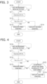
- the refrigerant leakage control will be specifically described with reference to the flowchart in FIG. 3 .
- the refrigerant leakage control is started when the refrigeration cycle apparatus 100 is activated.
- step S10 the control unit 8 determines whether a leakage of the refrigerant has been detected in any of the plurality of utilization units 1, specifically, whether a refrigerant has been detected by the refrigerant sensor 16. When determining that the refrigerant has been detected (Yes), the control unit 8 advances the process to step S11. When not determining that the refrigerant has been detected (No), the control unit 8 advances the process to step S10.
- step S11 the control unit 8 calculates a total value Pa of the capacities of the utilization units 1 excluding the utilization unit 1 in which the refrigerant has been detected, and advances the process to step S12.
- the total value Pa is a value calculated by summing the rated capacities (unit of which is horsepower or the like) of the utilization units 1 excluding the utilization unit 1 in which the refrigerant has been detected.
- the control unit 8 calculates the total value Pa by summing the rated capacities of the utilization units 1 excluding the utilization unit 1 in which the refrigerant has been detected.
- step S12 the control unit 8 determines whether the total value Pa is equal to or greater than a predetermined ratio R (50%) of a rated capacity Ps (unit of which is horsepower or the like) of the first heat source unit 2.
- a predetermined ratio R 50%) of a rated capacity Ps (unit of which is horsepower or the like) of the first heat source unit 2.
- the control unit 8 advances the process to step S13.
- the control unit 8 advances the process to step S14.
- step S13 the control unit 8 performs the first control and executes the refrigerant leakage control.
- the control unit 8 causes the flow path switching unit 3 to shut off the inflow of the refrigerant into the utilization unit 1 in which the leakage of the refrigerant has been detected.
- the control unit 8 closes the first shutoff valve 33 and the second shutoff valve 34 of the flow path switching unit 3 corresponding to the utilization unit 1 in which the leakage of the refrigerant has been detected.
- the control unit 8 continues the operation of the utilization units 1 except for the utilization unit 1 in which the refrigerant leakage has been detected.
- the control unit 8 closes the first shutoff valve 33a and the second shutoff valve 34a of the flow path switching unit 3a. At this time, the control unit 8 stops the operation of the utilization unit 1a. Along with this operation, the control unit 8 continues the operations of the utilization units 1b and 1c.
- step S14 the control unit 8 performs the second control and ends the refrigerant leakage control.
- the control unit 8 causes the flow path switching unit 3 to shut off the inflow of the refrigerant into the utilization unit 1 in which the leakage of the refrigerant has been detected.
- the control unit 8 stops the operation of all the utilization units 1 including the utilization unit 1 in which the leakage of the refrigerant has been detected.
- the control unit 8 closes the first shutoff valve 33a and the second shutoff valve 34a of the flow path switching unit 3a. Along with this operation, the control unit 8 stops the operations of the utilization units 1a to 1c.
- the refrigeration cycle apparatus 100 includes the first heat source unit 2, the plurality of utilization units 1, the flow path switching unit 3, and the control unit 8.
- the flow path switching unit 3 is provided between the first heat source unit 2 and the utilization units 1, and switches the flow of the refrigerant flowing between the first heat source unit 2 and the utilization units 1.
- the control unit 8 controls the first heat source unit 2, the utilization units 1, and the flow path switching unit 3.
- the control unit 8 When a leakage of the refrigerant is detected in any of the plurality of utilization units 1 during the air conditioning operation and the sum of the capacities of the utilization units 1 excluding the utilization unit 1 in which the leakage of the refrigerant has been detected is equal to or greater than the predetermined ratio R of the capacity of the first heat source unit 2, the control unit 8 performs first control of causing the flow path switching unit 3 to shut off the inflow of the refrigerant into the utilization unit 1 in which the leakage of the refrigerant has been detected and continuing the operation of the utilization units 1 excluding the utilization unit 1 in which the leakage of the refrigerant has been detected.
- the refrigeration cycle apparatus 100 even when the inflow of the refrigerant into the utilization unit 1 in which the leakage of the refrigerant has occurred is shut off, the operation of the remaining utilization units 1 can be continued. Therefore, the refrigeration cycle apparatus 100 can minimize degradation of comfort in the air conditioning target space even when a leakage of the refrigerant in the utilization unit 1 is detected and the inflow of the refrigerant into the utilization unit is shut off.
- control unit 8 When a leakage of the refrigerant is detected in any of the plurality of utilization units 1 during the air conditioning operation and the total capacity of the utilization units 1 excluding the utilization unit 1 in which the leakage of the refrigerant has been detected is less than the predetermined ratio R, the control unit 8 performs the second control to cause the flow path switching unit 3 to shut off the inflow of the refrigerant into the utilization unit 1 in which the leakage of the refrigerant has been detected and to stop the operation of the utilization units excluding the utilization unit 1 in which the leakage of the refrigerant has been detected.
- the refrigeration cycle apparatus 100 suppresses a decrease in comfort due to an inability to maintain operation with desired performance.
- the air conditioning operation includes the defrost operation.
- the predetermined ratio R is a ratio of a capacity of the utilization units 1 to the capacity of the first heat source unit 2, the ratio allowing the first heat source unit 2 to secure the amount of heat necessary for the refrigeration cycle apparatus 100 to execute the defrost operation.
- the total value of the heat absorption amounts in the utilization unit 1 decreases as compared with the case where the refrigerant flows into all the utilization units 1.
- frost cannot be sufficiently removed (in other words, the refrigeration cycle apparatus 100 cannot execute the defrost operation) due to an insufficient heat radiation amount in the heat source heat exchanger 24 during the defrost operation.
- control unit 8 determines whether to continue the operation of the utilization units 1 excluding the utilization unit 1 in which the leakage of the refrigerant has been detected on the basis of the predetermined ratio R when the inflow of the refrigerant into the utilization unit 1 in which the leakage of the refrigerant has been detected is shut off.
- the refrigeration cycle apparatus 100 executes the defrost operation as long as the first heat source unit 2 can secure a required amount of heat even when the inflow of the refrigerant into the utilization unit 1 is shut off.
- the refrigeration cycle apparatus 100 can execute the defrost operation while suppressing the degradation of the comfort of the air conditioning target space when the inflow of the refrigerant into the utilization unit 1 is shut off.
- control unit 8 may control various devices constituting the refrigeration cycle apparatus 100 in a cooling leakage control as described below.
- the control unit 8 Upon determining that the defrost operation is not scheduled to be performed, the control unit 8 performs the first control even when a leakage of the refrigerant is detected in any of the plurality of utilization units 1 during the air conditioning operation, and the sum of the capacities of the utilization units 1 excluding the utilization unit 1 in which the leakage of the refrigerant has been detected is less than the predetermined ratio R of the capacity of the heat source unit 2.
- a main difference between the flowchart illustrated in FIG. 3 and the flowchart illustrated in FIG. 4 is that the flowchart illustrated in FIG. 4 has step S15.
- step S12 the control unit 8 determines whether the total value Pa is equal to or greater than the predetermined ratio R (50%) of the rated capacity Ps of the first heat source unit 2.
- the control unit 8 advances the process to step S13.
- the control unit 8 advances the process to step S15.
- step S15 the control unit 8 determines whether the refrigeration cycle apparatus 100 is scheduled to perform the defrost operation. When determining that the refrigeration cycle apparatus 100 is scheduled to perform the defrost operation (Yes), the control unit 8 proceeds the process to step S14. When not determining that the refrigeration cycle apparatus 100 is scheduled to perform the defrost operation (No), the control unit 8 proceeds the process to step S13.
- Whether the refrigeration cycle apparatus 100 is scheduled to perform the defrost operation is determined on the basis of, for example, a setting as to whether the defrost operation needs to be executed.
- the setting as to whether the defrost operation needs to be executed is set by the user, for example. In a season with a relatively high temperature such as summer, there is almost no possibility of occurrence of frost, and thus the user may set the defrost operation to be unnecessary. In such a case, the control unit 8 determines that the defrost operation is not scheduled to be performed.
- the setting as to whether the defrost operation needs to be executed may be performed by the control unit 8 on the basis of a detection result of a temperature sensor and/or a humidity sensor (not illustrated).
- the refrigeration cycle apparatus 100 according to Modification A continues the operation of the remaining utilization units 1.
- the refrigeration cycle apparatus 100 according to Modification A can minimize degradation of comfort in the air conditioning target space even when a leakage of the refrigerant in the utilization unit 1 is detected and the inflow of the refrigerant into the utilization unit is shut off.
- control unit 8 may adjust a target evaporation temperature Te or a target condensation temperature Tc in the utilization heat exchanger 11 of the utilization unit 1 continuing the operation on the basis of the capacity of the utilization unit 1 in which the inflow of the refrigerant has been shut off.
- control unit 8 can reduce the target evaporation temperature Te in the utilization heat exchanger 11 of the utilization unit 1 continuing the operation on the basis of the rated capacity of the utilization unit 1 stopped in the first control.
- the control unit 8 can increase the target condensation temperature Tc in the utilization heat exchanger 11 of the utilization unit 1 continuing the operation on the basis of the rated capacity of the utilization unit 1 stopped in the first control.
- the refrigeration cycle apparatus 100 can minimize the degradation in comfort in the air conditioning target space.
- the control unit 8 may perform protection control on the basis of the capacity of the utilization unit 1 in which the inflow of the refrigerant has been shut off in the first control.
- the protection control is a control for protecting devices constituting the refrigeration cycle apparatus 100 from a temporary increase in refrigerant pressure in the refrigerant circuit 9 due to shutoff of inflow of the refrigerant in some of the utilization units 1.
- control unit 8 can lower a maximum number of rotations of the compressor 21 than usual as the protection control.
- the refrigeration cycle apparatus 100 according to Modification C can suppress damage to the devices caused by execution of the first control.
- the refrigeration cycle apparatus 100 may further include a second heat source unit 2a, and when the first control is performed, the second heat source unit 2a may perform an operation of compensating for the capacity of the utilization unit 1 in which the leakage of the refrigerant has been detected.
- the refrigeration cycle apparatus 100 further includes the second heat source unit 2a.
- the flow path switching unit 3 is provided between the second heat source unit 2a and the plurality of utilization units 1, and further switches the flow of the refrigerant flowing between the second heat source unit 2a and the plurality of utilization units 1.
- the control unit 8 causes the second heat source unit 2a to perform an operation of compensating for the capacity of the utilization unit 1 in which the inflow of the refrigerant has been shut off.
- control unit 8 refers to the rated capacity of each of the utilization units 1 recorded in the storage device, and causes the second heat source unit 2a to perform an operation of compensating for the rated capacity of the utilization unit 1 in which the inflow of the refrigerant has been shut off.
- the refrigeration cycle apparatus 100 can minimize the degradation in comfort in the air conditioning target space.
- the mode of the flow path switching unit 3 is not limited to an individual type in which the corresponding utilization units 1 are installed at different positions.
- the flow path switching unit 3 may be a collective type in which the first branch pipe 31, the second branch pipe 32, the first shutoff valve 33, and the second shutoff valve 34 included in the plurality of flow path switching units 3 are accommodated in one casing.
- the predetermined ratio R may be other than 50%.
- the predetermined ratio R may be calculated on the basis of a value other than the ratio of the total value of the capacities of the utilization units 1 required for the refrigeration cycle apparatus 100 to execute the defrost operation to the capacity of the first heat source unit 2.
- Patent Literature 1 WO 2016/129027 A
Landscapes
- Engineering & Computer Science (AREA)
- Mechanical Engineering (AREA)
- General Engineering & Computer Science (AREA)
- Physics & Mathematics (AREA)
- Thermal Sciences (AREA)
- Chemical & Material Sciences (AREA)
- Combustion & Propulsion (AREA)
- Air Conditioning Control Device (AREA)
Abstract
Description
- The present disclosure relates to a refrigeration cycle apparatus.
- Patent Literature 1 (
WO 2016/129027 A ) discloses an air conditioner including a plurality of shutoff devices that is each installed between a plurality of heat source devices and an indoor unit and shuts off a flow of a refrigerant flowing through a refrigerant pipe, a plurality of leakage detectors that each detects a refrigerant leakage from each of the heat source devices, and a control device that controls operations of the plurality of heat source devices, the indoor unit, and the shutoff devices. - When a leakage of the refrigerant is detected by the leakage detector, the control device of the air conditioner activates the shutoff device connected to the heat source device from which the refrigerant leaks. In the plurality of shutoff devices, when the shutoff device in an activated state and the shutoff device in a non-activated state exist, the control device obtains a limited heat exchange capability of the indoor unit when the operation is performed by the heat source device connected to the shutoff device in the non-activated state, and controls the operation of the heat source device or the indoor unit with the limited heat exchange capability as an upper limit. As a result, the air conditioner of Patent Literature 1 can minimize degradation of comfort of an air conditioning target space even when the leakage of the refrigerant is shut off.
- When a leakage of the refrigerant is detected in a utilization unit (indoor unit) and an inflow of the refrigerant into the utilization unit in which the refrigerant leaks is shut off, there has been room for study as to how to determine whether to continue the operation of the other utilization units.
- An object of the present disclosure is to provide a refrigeration cycle apparatus capable of minimizing degradation of comfort in an air conditioning target space even when a leakage of a refrigerant in a utilization unit is detected and an inflow of a refrigerant into the utilization unit is shut off.
- A refrigeration cycle apparatus according to a first aspect performs an air conditioning operation. The refrigeration cycle apparatus includes a first heat source unit, a plurality of utilization units, a flow path switching unit, and a control unit.
- The flow path switching unit is provided between the first heat source unit and the utilization units, and switches a flow of a refrigerant flowing between the first heat source unit and the utilization units. The control unit controls the first heat source unit, the utilization units, and the flow path switching unit.
- When a leakage of the refrigerant is detected in any of the plurality of utilization units during the air conditioning operation and a sum of capacities of the utilization units excluding the utilization unit in which the leakage of the refrigerant has been detected is equal to or greater than a predetermined ratio of a capacity of the first heat source unit, the control unit performs first control of causing the flow path switching unit to shut off an inflow of the refrigerant into the utilization unit in which the leakage of the refrigerant has been detected and continuing an operation of the utilization units excluding the utilization unit in which the leakage of the refrigerant has been detected.
- In the refrigeration cycle apparatus, even when the inflow of the refrigerant into the utilization unit in which the leakage of the refrigerant has occurred is shut off, operation of the remaining utilization units can be continued. Therefore, the refrigeration cycle apparatus can minimize degradation of comfort in an air conditioning target space even when a leakage of the refrigerant in the utilization unit is detected and the inflow of the refrigerant into the utilization unit is shut off.
- A refrigeration cycle apparatus according to a second aspect is the refrigeration cycle apparatus according to the first aspect, in which when a leakage of the refrigerant is detected in any of the plurality of utilization units during the air conditioning operation and the sum of the capacities of the utilization units excluding the utilization unit in which the leakage of the refrigerant has been detected is less than the predetermined ratio of the capacity of the first heat source unit, the control unit performs second control of causing the flow path switching unit to shut off the inflow of the refrigerant into the utilization unit in which the leakage of the refrigerant has been detected and stopping the operation of all the utilization units including the utilization unit in which the leakage of the refrigerant has been detected.
- Therefore, the refrigeration cycle apparatus suppresses a decrease in comfort due to an inability to maintain operation with desired performance.
- A refrigeration cycle apparatus according to a third aspect is the refrigeration cycle apparatus according to the first or second aspect, in which the air conditioning operation includes a defrost operation. The predetermined ratio is a ratio of capacities of the utilization units to the capacity of the first heat source unit, the ratio allowing the first heat source unit to secure an amount of heat necessary for the refrigeration cycle apparatus to execute the defrost operation.
- The refrigeration cycle apparatus can execute the defrost operation while suppressing the degradation of the comfort of the air conditioning target space when the inflow of the refrigerant into the utilization unit is shut off.
- A refrigeration cycle apparatus according to a fourth aspect is the refrigeration cycle apparatus according to the third aspect, in which upon determining that the defrost operation is not scheduled to be performed, the control unit performs the first control even when a leakage of the refrigerant is detected in any of the plurality of utilization units during the air conditioning operation, and the sum of the capacities of the utilization units excluding the utilization unit in which the leakage of the refrigerant has been detected is less than the predetermined ratio of the capacity of the first heat source unit.
- The refrigeration cycle apparatus continues operation of the remaining utilization units. Therefore, the refrigeration cycle apparatus can minimize degradation of comfort in the air conditioning target space even when a leakage of the refrigerant in the utilization unit is detected and the inflow of the refrigerant into the utilization unit is shut off.
- A refrigeration cycle apparatus according to a fifth aspect is the refrigeration cycle apparatus according to any of the first to fourth aspects, in which the utilization units each include a utilization heat exchanger. In the first control, the control unit adjusts a target evaporation temperature or a target condensation temperature in the utilization heat exchanger of the utilization unit continuing the operation on the basis of the capacity of the utilization unit in which the inflow of the refrigerant has been shut off.
- Since the utilization unit continuing operation compensates for a decrease in output of the utilization unit in which the inflow of the refrigerant has been shut off and the operation is stopped, the refrigeration cycle apparatus can minimize the degradation in comfort in the air conditioning target space.
- A refrigeration cycle apparatus according to a sixth aspect is the refrigeration cycle apparatus according to any of the first to fifth aspects, in which, in the first control, the control unit performs protection control on the basis of the capacity of the utilization unit in which the inflow of the refrigerant has been shut off.
- The refrigeration cycle apparatus can suppress damage to devices caused by execution of the first control.
- A refrigeration cycle apparatus according to a seventh aspect is the refrigeration cycle apparatus according to any of the first to sixth aspects and further includes a second heat source unit. The flow path switching unit is provided between the second heat source unit and the plurality of utilization units, and further switches the flow of the refrigerant flowing between the second heat source unit and the plurality of utilization units.
- When performing the first control, the control unit causes the second heat source unit to perform an operation of compensating for the capacity of the utilization unit in which the inflow of the refrigerant has been shut off.
- Since the second heat source unit compensates for a decrease in output of the utilization unit in which the inflow of the refrigerant has been shut off and the operation is stopped in the first control, the refrigeration cycle apparatus can minimize the degradation in comfort in the air conditioning target space.
-
-
FIG. 1 is a schematic configuration diagram of arefrigeration cycle apparatus 100. -
FIG. 2 is a block diagram of acontrol unit 8. -
FIG. 3 is a flowchart illustrating a control flow of refrigerant leakage control. -
FIG. 4 is a flowchart illustrating a control flow of refrigerant leakage control performed by arefrigeration cycle apparatus 100 according to Modification A. -
FIG. 5 is a schematic configuration diagram of arefrigeration cycle apparatus 100 according to Modification D. - A
refrigeration cycle apparatus 100 performs an air conditioning operation (specifically, a cooling only operation, a heating only operation, a defrost operation, and a simultaneous cooling and heating operation) in an air conditioning target space by performing a vapor compression refrigeration cycle. Examples of the air conditioning target space include spaces in buildings such as office buildings, commercial facilities, and residences. The refrigeration cycle apparatus merely exemplifies a refrigerant cycle apparatus. A heat exchanger of the present disclosure may be used for a different refrigerant cycle apparatus such as a refrigerator, a freezer, a hot water supplier, or a floor heater. - As illustrated in
FIG. 1 , therefrigeration cycle apparatus 100 mainly includes three utilization units 1, oneheat source unit 2, three flow path switching units 3, one liquid-refrigerant connection pipe 5, one low-pressure gas-refrigerant connection pipe 6, one high-pressure gas-refrigerant connection pipe 7, and onecontrol unit 8. The number of the utilization units 1 and the number of the flow path switching units 3 are not limited to three, and may be two, or four or more. - The liquid-
refrigerant connection pipe 5, the low-pressure gas-refrigerant connection pipe 6, and the high-pressure gas-refrigerant connection pipe 7 are refrigerant connection pipes that connect the utilization unit 1 and theheat source unit 2. In therefrigeration cycle apparatus 100, the utilization units 1 and theheat source unit 2 are connected via the liquid-refrigerant connection pipe 5, the low-pressure gas-refrigerant connection pipe 6, and the high-pressure gas-refrigerant connection pipe 7 to constitute arefrigerant circuit 9. - In addition to the air conditioning operation, the
refrigeration cycle apparatus 100 also performs refrigerant leakage control for the purpose of suppressing further leakage of the refrigerant while minimizing deterioration in comfort in the air conditioning target space when a leakage of the refrigerant is detected in any of the plurality of utilization units 1. - Each of the utilization units 1 mainly includes a utilization heat exchanger 11, a utilization fan 12, a utilization expansion mechanism 13, a liquid refrigerant pipe 14, a
gas refrigerant pipe 15, and a refrigerant sensor 16. - Hereinafter, when it is necessary to distinguish the three utilization units 1 and devices included in the utilization units 1, any of subscripts a, b, or c will be added at the end of the reference signs of the utilization units 1 and the devices included in the utilization units 1 as illustrated in
FIG. 1 . - The utilization heat exchanger 11 causes heat exchange between the refrigerant and air carried by an airflow generated by the utilization fan 12. The utilization heat exchanger 11 has a liquid side connected to the liquid-
refrigerant connection pipe 5 via the liquid refrigerant pipe 14, and a gas side connected to the flow path switching unit 3 via thegas refrigerant pipe 15. - The utilization fan 12 supplies air to the utilization heat exchanger 11.
- The utilization expansion mechanism 13 adjusts pressure and a flow rate of the refrigerant flowing through the liquid refrigerant pipe 14. The utilization expansion mechanism 13 is provided on the liquid refrigerant pipe 14.
- The refrigerant sensor 16 is provided at an installation site of the utilization unit 1 and detects a refrigerant. In other words, the refrigerant sensor 16 detects a leakage of the refrigerant in the air conditioning target space.
- The
heat source unit 2 mainly includes acompressor 21, a first three-way valve 22, a second three-way valve 23, a heatsource heat exchanger 24, a heatsource expansion mechanism 25, and aheat source fan 26. - The
compressor 21 sucks a low-pressure refrigerant in the refrigeration cycle from therefrigerant circuit 9 via asuction portion 21a, compresses the refrigerant by a compression mechanism (not illustrated), and discharges the refrigerant to therefrigerant circuit 9 via adischarge portion 21b. - The
suction portion 21a of thecompressor 21 is connected to the low-pressure gas-refrigerant connection pipe 6, and thedischarge portion 21b is connected to afirst port 22a of the first three-way valve 22 and afirst port 23a of the second three-way valve 23 (which will be both described later). - The first three-
way valve 22 has three ports of thefirst port 22a, asecond port 22b, and athird port 22c. Thefirst port 22a of the first three-way valve 22 is connected to thedischarge portion 21b of thecompressor 21, thesecond port 22b is connected to a gas side of the heatsource heat exchanger 24, and thethird port 22c is connected to thesuction portion 21a of thecompressor 21. - The second three-
way valve 23 has three ports of thefirst port 23a, asecond port 23b, and athird port 23c. Thefirst port 23a of the second three-way valve 23 is connected to thedischarge portion 21b of thecompressor 21, thesecond port 23b is connected to the high-pressure gas-refrigerant connection pipe 7, and thethird port 23c is connected to the low-pressure gas-refrigerant connection pipe 6 and thesuction portion 21a of thecompressor 21. - The first three-
way valve 22 and the second three-way valve 23 can change between a state in which thefirst ports second ports third ports second ports third ports first ports - The heat
source heat exchanger 24 causes heat exchange between a refrigerant flowing inside and a heat source (for example, air at an installation site of the heat source unit 2). - The heat
source heat exchanger 24 has a gas side connected to thesecond port 22b of the first three-way valve 22, and a liquid side connected to the liquid-refrigerant connection pipe 5 via the heatsource expansion mechanism 25. - The heat
source expansion mechanism 25 adjusts pressure and a flow rate of the refrigerant flowing inside. The heatsource expansion mechanism 25 is provided in a pipe connecting the liquid side of the heatsource heat exchanger 24 and the liquid-refrigerant connection pipe 5. - The
heat source fan 26 supplies external air as a heat source to the heatsource heat exchanger 24. - The flow path switching unit 3 is provided between the
heat source unit 2 and each of the utilization units 1, and switches the flow of the refrigerant flowing between the first heat source unit and the utilization unit 1. The flow path switching unit 3 includes a first branch pipe 31, a second branch pipe 32, a first shutoff valve 33, and a second shutoff valve 34. - Hereinafter, when it is necessary to distinguish the three flow path switching units 3, as illustrated in
FIG. 1 , any of subscripts a, b, or c added to the corresponding utilization unit 1 will be added to the end of the devices included in the flow path switching unit 3 and the flow path switching unit 3. - The first branch pipe 31 is a pipe that connects the
gas refrigerant pipe 15 of the utilization unit 1 and the low-pressure gas-refrigerant connection pipe 6. The second branch pipe 32 is a pipe that connects thegas refrigerant pipe 15 of the utilization unit 1 and the high-pressure gas-refrigerant connection pipe 7. - The first shutoff valve 33 is an openable and closable electromagnetic valve provided in the first branch pipe 31. The second shutoff valve 34 is an openable and closable electromagnetic valve provided in the second branch pipe 32.
- When the first shutoff valve 33 is closed, the flow of the refrigerant through the first branch pipe 31 is shut off. When the second shutoff valve 34 is closed, the flow of the refrigerant through the second branch pipe 32 is shut off.
- The
control unit 8 controls operations of various devices constituting therefrigeration cycle apparatus 100. - As illustrated in
FIG. 2 , thecontrol unit 8 is electrically connected to the utilization fan 12, the utilization expansion mechanism 13, the refrigerant sensor 16, thecompressor 21, the first three-way valve 22, the second three-way valve 23, the heatsource expansion mechanism 25, theheat source fan 26, the first shutoff valve 33, and the second shutoff valve 34 so as to transmit and receive signals. Thecontrol unit 8 may be electrically connected to various sensors (not illustrated) provided in the utilization unit 1 and theheat source unit 2. Thecontrol unit 8 may be communicable with a remote controller (not illustrated) operated by a user of therefrigeration cycle apparatus 100. - The
control unit 8 is implemented by a computer. Thecontrol unit 8 includes a control arithmetic device and a storage device (which are both not illustrated). The control arithmetic device includes a processor such as a CPU or a GPU. The control arithmetic device reads a program stored in the storage device and executes predetermined image processing or arithmetic processing in accordance with the program. Furthermore, the control arithmetic device writes an arithmetic result to the storage device and reads information stored in the storage device in accordance with the program. - A rated capacity of each utilization unit 1, a rated capacity of the first
heat source unit 2, and a predetermined ratio R (described later) are recorded in the storage device. - During the air conditioning operation, the
control unit 8 of therefrigeration cycle apparatus 100 controls various devices constituting therefrigeration cycle apparatus 100 as described below. Although detailed description is omitted, thecontrol unit 8 appropriately controls the numbers of rotations of the utilization fan 12 and theheat source fan 26 during any operation. - The cooling only operation is an operation in which all the utilization units 1 perform the cooling operation.
- In the cooling only operation, the
first port 22a and thesecond port 22b of the first three-way valve 22 communicate with each other. In each flow path switching unit 3, the first shutoff valve 33 is opened, and the second shutoff valve 34 is closed. - Since all the second shutoff valves 34 are closed, the refrigerant hardly passes through the second three-
way valve 23. Therefore, the state of the second three-way valve 23 is not limited. - When the
compressor 21 is activated, the refrigerant discharged from thecompressor 21 passes through the first three-way valve 22 and then flows through the heatsource heat exchanger 24. In the heatsource heat exchanger 24, the refrigerant radiates heat to outdoor air and condenses. The refrigerant having condensed in the heatsource heat exchanger 24 passes through the heatsource expansion mechanism 25 set in a fully open state, flows through the liquid-refrigerant connection pipe 5, and is divided into the utilization units 1. - In all the utilization units 1, when the refrigerant passes through the utilization expansion mechanism 13, the refrigerant is decompressed to a low pressure and flows through the utilization heat exchanger 11. In the utilization heat exchanger 11, the refrigerant absorbs heat from air in the air conditioning target space and evaporates. As a result, the air conditioning target space corresponding to the utilization unit 1 is cooled. An opening degree of the utilization expansion mechanism 13 is adjusted in accordance with a degree of superheating of the refrigerant obtained by a temperature sensor (not illustrated) or the like.
- The refrigerant having flowed out of each of the utilization units 1 flows through the first branch pipe 31 of each of the flow path switching units 3, and joins at the low-pressure gas-
refrigerant connection pipe 6. The refrigerant having joined at the low-pressure gas-refrigerant connection pipe 6 is sucked into thecompressor 21 and compressed again. - The heating only operation is an operation in which all the utilization units 1 perform the heating operation.
- In the heating only operation, in the first three-
way valve 22, thesecond port 22b and thethird port 22c communicate with each other, and in the second three-way valve 23, thefirst port 23a and thesecond port 23b communicate with each other. In each flow path switching unit 3, the first shutoff valve 33 is closed, and the second shutoff valve 34 is opened. - When the
compressor 21 is activated, the refrigerant discharged from thecompressor 21 passes through the second three-way valve 23, then flows through the high-pressure gas-refrigerant connection pipe 7, and is divided to the second branch pipes 32 of the respective flow path switching units 3. The refrigerant having passed through the flow path switching units 3 flows to the corresponding utilization units 1. - In all the utilization units 1, the refrigerant radiates heat to the air in the air conditioning target space and condenses in the utilization heat exchanger 11. As a result, the air conditioning target space corresponding to the utilization unit 1 is heated. The refrigerant having condensed in the utilization heat exchanger 11 passes through the utilization expansion mechanism 13. An opening degree of the utilization expansion mechanism 13 is adjusted in accordance with a degree of subcooling of the refrigerant obtained by the temperature sensor (not illustrated) or the like.
- The refrigerant having flowed out of the utilization units 1 joins at the liquid-
refrigerant connection pipe 5. When passing through the heatsource expansion mechanism 25, the refrigerant having joined at the liquid-refrigerant connection pipe 5 is decompressed to a low pressure and flows through the heatsource heat exchanger 24. In the heatsource heat exchanger 24, the refrigerant absorbs heat from the outdoor air and evaporates. The refrigerant having evaporated in the heatsource heat exchanger 24 passes through the first three-way valve 22, is then sucked into thecompressor 21, and is compressed again. - An object of the defrost operation is to remove frost generated on an outer surface of the heat
source heat exchanger 24 when the heating only operation is performed in an environment with a low outside air temperature in winter and the like. In the defrost operation, thecontrol unit 8 performs a refrigeration cycle similar to the refrigeration cycle in the cooling only operation while stopping theheat source fan 26. As a result, frost generated on the outer surface of the heatsource heat exchanger 24 is removed by heat radiation from the refrigerant having condensed in the heatsource heat exchanger 24. The operations of the various devices constituting therefrigeration cycle apparatus 100 in the defrost operation are similar to the operations in the cooling only operation except for the operation of theheat source fan 26, and thus detailed description of the operations is omitted. - The simultaneous cooling and heating operation is an operation in which some of the utilization units 1 perform the heating operation of the air conditioning target space, while the remaining utilization units 1 perform the cooling operation of the air conditioning target space. The simultaneous cooling and heating operation includes a first simultaneous cooling and heating operation and a second simultaneous cooling and heating operation.
- The first simultaneous cooling and heating operation is a heating based operation in which the number of the utilization units 1 that perform the heating operation is larger than the number of the utilization units 1 that perform the cooling operation. Hereinafter, a case where
utilization units utilization unit 1c performs the cooling operation will be described as an example. - In the first simultaneous cooling and heating operation, in the first three-
way valve 22, thefirst port 22a and thesecond port 22b communicate with each other, and in the second three-way valve 23, thefirst port 23a and thesecond port 23b communicate with each other. In flowpath switching units utilization units path switching unit 3c corresponding to theutilization unit 1c, the first shutoff valve 33 is opened, and the second shutoff valve 34 is closed. - When the
compressor 21 is activated, the refrigerant discharged from thecompressor 21 is divided into the first three-way valve 22 and the second three-way valve 23. The refrigerant having passed through the first three-way valve 22 condenses in the heatsource heat exchanger 24, passes through the heatsource expansion mechanism 25 adjusted to a predetermined opening degree, and flows through the liquid-refrigerant connection pipe 5. On the other hand, the refrigerant having passed through the second three-way valve 23 flows through the high-pressure gas-refrigerant connection pipe 7 and flows into the second branch pipe 32 of the flowpath switching units utilization units - In the
utilization units utilization units utilization units refrigerant connection pipe 5. - The refrigerant having joined at the liquid-
refrigerant connection pipe 5 flows into theutilization unit 1c. The refrigerant having flowed into theutilization unit 1c is decompressed to a low pressure when passing through the utilization expansion mechanism 13, and then flows through the utilization heat exchanger 11. In the utilization heat exchanger 11, the refrigerant absorbs heat from air in the air conditioning target space and evaporates. As a result, the air conditioning target space corresponding to theutilization unit 1c is cooled. The refrigerant used for cooling the air conditioning target space in theutilization unit 1c passes through the first branch pipe 31 of the flowpath switching unit 3c corresponding to theutilization unit 1c, then flows through the low-pressure gas-refrigerant connection pipe 6, is sucked into thecompressor 21, and is compressed again. - The second simultaneous cooling and heating operation is a cooling based operation in which the number of the utilization units 1 that perform the heating operation is smaller than the number of the utilization units 1 that perform the cooling operation. Hereinafter, a case where the
utilization unit 1a performs the heating operation and theutilization units - In the second simultaneous cooling and heating operation, in the first three-
way valve 22, thefirst port 22a and thesecond port 22b communicate with each other, and in the second three-way valve 23, thefirst port 23a and thesecond port 23b communicate with each other. In the flowpath switching unit 3a corresponding to theutilization unit 1a performing the heating operation, the first shutoff valve 33 is closed, and the second shutoff valve 34 is opened. Furthermore, in a flowpath switching units utilization units - When the
compressor 21 is activated, the refrigerant discharged from thecompressor 21 is divided into the first three-way valve 22 and the second three-way valve 23. The refrigerant having passed through the first three-way valve 22 condenses in the heatsource heat exchanger 24, passes through the heatsource expansion mechanism 25 adjusted to a predetermined opening degree, and flows through the liquid-refrigerant connection pipe 5. On the other hand, the refrigerant having passed through the second three-way valve 23 flows through the high-pressure gas-refrigerant connection pipe 7 and flows into the second branch pipe 32 of the flowpath switching unit 3a corresponding to theutilization unit 1a. The refrigerant having flowed out of the second branch pipe 32 flows into the corresponding utilization unit 1. - In the
utilization unit 1a, the refrigerant radiates heat to the air in the air conditioning target space and condenses in the utilization heat exchanger 11. As a result, the air conditioning target space corresponding to theutilization unit 1a is heated. The refrigerant having condensed in the utilization heat exchanger 11 passes through the utilization expansion mechanism 13. The opening degree of the utilization expansion mechanism 13 is adjusted in accordance with the degree of subcooling of the refrigerant obtained by the temperature sensor (not illustrated) or the like. The refrigerant having flowed out of theutilization unit 1a flows to the liquid-refrigerant connection pipe 5. - The refrigerant having flowed into the liquid-
refrigerant connection pipe 5 is divided into theutilization units utilization units utilization units path switching units refrigerant connection pipe 6, is sucked into thecompressor 21, and is compressed again. - In the refrigerant leakage control, the
control unit 8 controls various devices constituting therefrigeration cycle apparatus 100 as described below. - The
control unit 8 performs first control when a leakage of the refrigerant is detected in any of the plurality of utilization units 1 (in other words, the refrigerant sensor 16 detects the refrigerant) during the air conditioning operation, and the sum of the capacities (rated capacities) of the utilization units 1 excluding the utilization unit 1 in which the leakage of the refrigerant has been detected is equal to or greater than a predetermined ratio R of the capacity (rated capacity) of the firstheat source unit 2. - In the first control, the
control unit 8 causes the flow path switching unit 3 to shut off the inflow of the refrigerant into the utilization unit 1 in which the leakage of the refrigerant has been detected, and continues the operation of the utilization units 1 excluding the utilization unit 1 in which the leakage of the refrigerant has been detected. - The
control unit 8 performs second control when a leakage of the refrigerant is detected in any of the plurality of utilization units 1 (in other words, the refrigerant sensor 16 detects the refrigerant) during the air conditioning operation, and the sum of the capacities of the utilization units 1 excluding the utilization unit 1 in which the leakage of the refrigerant has been detected is less than a predetermined ratio R of the capacity of the firstheat source unit 2. - In the second control, the
control unit 8 causes the flow path switching unit 3 to shut off the inflow of the refrigerant into the utilization unit 1 in which the leakage of the refrigerant has been detected, and stops the operation of all the utilization units 1 including the utilization unit 1 in which the leakage of the refrigerant has been detected. - The predetermined ratio R is a ratio of a capacity of the utilization unit 1 (a total value of the capacities when the plurality of utilization units 1 are used) to a capacity of the first
heat source unit 2, the ratio allowing the firstheat source unit 2 to secure an amount of heat necessary for therefrigeration cycle apparatus 100 to execute the defrost operation. The amount of heat required for therefrigeration cycle apparatus 100 to execute the defrost operation is an amount of heat required for the heatsource heat exchanger 24 to remove frost generated on the outer surface. In the present embodiment, the predetermined ratio R is 50%. - The refrigerant leakage control will be specifically described with reference to the flowchart in
FIG. 3 . The refrigerant leakage control is started when therefrigeration cycle apparatus 100 is activated. - In step S10, the
control unit 8 determines whether a leakage of the refrigerant has been detected in any of the plurality of utilization units 1, specifically, whether a refrigerant has been detected by the refrigerant sensor 16. When determining that the refrigerant has been detected (Yes), thecontrol unit 8 advances the process to step S11. When not determining that the refrigerant has been detected (No), thecontrol unit 8 advances the process to step S10. - In step S11, the
control unit 8 calculates a total value Pa of the capacities of the utilization units 1 excluding the utilization unit 1 in which the refrigerant has been detected, and advances the process to step S12. Here, the total value Pa is a value calculated by summing the rated capacities (unit of which is horsepower or the like) of the utilization units 1 excluding the utilization unit 1 in which the refrigerant has been detected. - The
control unit 8 calculates the total value Pa by summing the rated capacities of the utilization units 1 excluding the utilization unit 1 in which the refrigerant has been detected. - In step S12, the
control unit 8 determines whether the total value Pa is equal to or greater than a predetermined ratio R (50%) of a rated capacity Ps (unit of which is horsepower or the like) of the firstheat source unit 2. When the total value Pa is equal to or greater than the predetermined ratio R of the rated capacity Ps of the first heat source unit 2 (Yes), thecontrol unit 8 advances the process to step S13. When the total value Pa is not equal to or greater than the predetermined ratio R (50%) of the rated capacity Ps of the first heat source unit 2 (the total value Pa is less than the predetermined ratio R) (No), thecontrol unit 8 advances the process to step S14. - In step S13, the
control unit 8 performs the first control and executes the refrigerant leakage control. In the first control, thecontrol unit 8 causes the flow path switching unit 3 to shut off the inflow of the refrigerant into the utilization unit 1 in which the leakage of the refrigerant has been detected. Specifically, thecontrol unit 8 closes the first shutoff valve 33 and the second shutoff valve 34 of the flow path switching unit 3 corresponding to the utilization unit 1 in which the leakage of the refrigerant has been detected. Along with this operation, thecontrol unit 8 continues the operation of the utilization units 1 except for the utilization unit 1 in which the refrigerant leakage has been detected. - For example, when the first control is performed in response to a refrigerant detected by the refrigerant sensor 16 of the
utilization unit 1a, thecontrol unit 8 closes thefirst shutoff valve 33a and thesecond shutoff valve 34a of the flowpath switching unit 3a. At this time, thecontrol unit 8 stops the operation of theutilization unit 1a. Along with this operation, thecontrol unit 8 continues the operations of theutilization units - In step S14, the
control unit 8 performs the second control and ends the refrigerant leakage control. In the second control, thecontrol unit 8 causes the flow path switching unit 3 to shut off the inflow of the refrigerant into the utilization unit 1 in which the leakage of the refrigerant has been detected. Along with this operation, thecontrol unit 8 stops the operation of all the utilization units 1 including the utilization unit 1 in which the leakage of the refrigerant has been detected. - For example, when the second control is performed in response to a refrigerant detected by the refrigerant sensor 16 of the
utilization unit 1a, thecontrol unit 8 closes thefirst shutoff valve 33a and thesecond shutoff valve 34a of the flowpath switching unit 3a. Along with this operation, thecontrol unit 8 stops the operations of theutilization units 1a to 1c. - (4-1)
Therefrigeration cycle apparatus 100 includes the firstheat source unit 2, the plurality of utilization units 1, the flow path switching unit 3, and thecontrol unit 8. - The flow path switching unit 3 is provided between the first
heat source unit 2 and the utilization units 1, and switches the flow of the refrigerant flowing between the firstheat source unit 2 and the utilization units 1. Thecontrol unit 8 controls the firstheat source unit 2, the utilization units 1, and the flow path switching unit 3. - When a leakage of the refrigerant is detected in any of the plurality of utilization units 1 during the air conditioning operation and the sum of the capacities of the utilization units 1 excluding the utilization unit 1 in which the leakage of the refrigerant has been detected is equal to or greater than the predetermined ratio R of the capacity of the first
heat source unit 2, thecontrol unit 8 performs first control of causing the flow path switching unit 3 to shut off the inflow of the refrigerant into the utilization unit 1 in which the leakage of the refrigerant has been detected and continuing the operation of the utilization units 1 excluding the utilization unit 1 in which the leakage of the refrigerant has been detected. - In the
refrigeration cycle apparatus 100, even when the inflow of the refrigerant into the utilization unit 1 in which the leakage of the refrigerant has occurred is shut off, the operation of the remaining utilization units 1 can be continued. Therefore, therefrigeration cycle apparatus 100 can minimize degradation of comfort in the air conditioning target space even when a leakage of the refrigerant in the utilization unit 1 is detected and the inflow of the refrigerant into the utilization unit is shut off. - (4-2)
When a leakage of the refrigerant is detected in any of the plurality of utilization units 1 during the air conditioning operation and the total capacity of the utilization units 1 excluding the utilization unit 1 in which the leakage of the refrigerant has been detected is less than the predetermined ratio R, thecontrol unit 8 performs the second control to cause the flow path switching unit 3 to shut off the inflow of the refrigerant into the utilization unit 1 in which the leakage of the refrigerant has been detected and to stop the operation of the utilization units excluding the utilization unit 1 in which the leakage of the refrigerant has been detected. - The
refrigeration cycle apparatus 100 suppresses a decrease in comfort due to an inability to maintain operation with desired performance. - (4-3)
The air conditioning operation includes the defrost operation. The predetermined ratio R is a ratio of a capacity of the utilization units 1 to the capacity of the firstheat source unit 2, the ratio allowing the firstheat source unit 2 to secure the amount of heat necessary for therefrigeration cycle apparatus 100 to execute the defrost operation. - By shutting off the flow of the refrigerant into the utilization unit 1 in which the leakage of the refrigerant has been detected, the total value of the heat absorption amounts in the utilization unit 1 (specifically, the utilization heat exchanger 11) decreases as compared with the case where the refrigerant flows into all the utilization units 1. As a result, there is a possibility that frost cannot be sufficiently removed (in other words, the
refrigeration cycle apparatus 100 cannot execute the defrost operation) due to an insufficient heat radiation amount in the heatsource heat exchanger 24 during the defrost operation. - In the present embodiment, the
control unit 8 determines whether to continue the operation of the utilization units 1 excluding the utilization unit 1 in which the leakage of the refrigerant has been detected on the basis of the predetermined ratio R when the inflow of the refrigerant into the utilization unit 1 in which the leakage of the refrigerant has been detected is shut off. Therefrigeration cycle apparatus 100 executes the defrost operation as long as the firstheat source unit 2 can secure a required amount of heat even when the inflow of the refrigerant into the utilization unit 1 is shut off. - Therefore, the
refrigeration cycle apparatus 100 can execute the defrost operation while suppressing the degradation of the comfort of the air conditioning target space when the inflow of the refrigerant into the utilization unit 1 is shut off. - When the air conditioning operation includes the defrost operation, the
control unit 8 may control various devices constituting therefrigeration cycle apparatus 100 in a cooling leakage control as described below. - Upon determining that the defrost operation is not scheduled to be performed, the
control unit 8 performs the first control even when a leakage of the refrigerant is detected in any of the plurality of utilization units 1 during the air conditioning operation, and the sum of the capacities of the utilization units 1 excluding the utilization unit 1 in which the leakage of the refrigerant has been detected is less than the predetermined ratio R of the capacity of theheat source unit 2. - With reference to the flowchart in
FIG. 4 , the refrigerant leakage control performed by therefrigeration cycle apparatus 100 according to Modification A will be specifically described focusing on a difference from the flowchart illustrated inFIG. 3 . Hereinafter, description of the steps already described is omitted. - A main difference between the flowchart illustrated in
FIG. 3 and the flowchart illustrated inFIG. 4 is that the flowchart illustrated inFIG. 4 has step S15. - In step S12, the
control unit 8 determines whether the total value Pa is equal to or greater than the predetermined ratio R (50%) of the rated capacity Ps of the firstheat source unit 2. When the total value Pa is equal to or greater than the predetermined ratio R of the rated capacity Ps of the first heat source unit 2 (Yes), thecontrol unit 8 advances the process to step S13. When the total value Pa is not equal to or greater than the predetermined ratio R (50%) of the rated capacity Ps of the first heat source unit 2 (the total value Pa is less than the predetermined ratio R) (No), thecontrol unit 8 advances the process to step S15. - In step S15, the
control unit 8 determines whether therefrigeration cycle apparatus 100 is scheduled to perform the defrost operation. When determining that therefrigeration cycle apparatus 100 is scheduled to perform the defrost operation (Yes), thecontrol unit 8 proceeds the process to step S14. When not determining that therefrigeration cycle apparatus 100 is scheduled to perform the defrost operation (No), thecontrol unit 8 proceeds the process to step S13. - Whether the
refrigeration cycle apparatus 100 is scheduled to perform the defrost operation is determined on the basis of, for example, a setting as to whether the defrost operation needs to be executed. The setting as to whether the defrost operation needs to be executed is set by the user, for example. In a season with a relatively high temperature such as summer, there is almost no possibility of occurrence of frost, and thus the user may set the defrost operation to be unnecessary. In such a case, thecontrol unit 8 determines that the defrost operation is not scheduled to be performed. The setting as to whether the defrost operation needs to be executed may be performed by thecontrol unit 8 on the basis of a detection result of a temperature sensor and/or a humidity sensor (not illustrated). - When the defrost operation is not scheduled, it is unnecessary to consider securing the amount of heat necessary for executing the defrost operation even when the inflow of the refrigerant into the utilization unit 1 in which the leakage of the refrigerant has occurred is shut off. Therefore, when the defrost operation is not scheduled, the
refrigeration cycle apparatus 100 according to Modification A continues the operation of the remaining utilization units 1. Therefrigeration cycle apparatus 100 according to Modification A can minimize degradation of comfort in the air conditioning target space even when a leakage of the refrigerant in the utilization unit 1 is detected and the inflow of the refrigerant into the utilization unit is shut off. - In the first control, the
control unit 8 may adjust a target evaporation temperature Te or a target condensation temperature Tc in the utilization heat exchanger 11 of the utilization unit 1 continuing the operation on the basis of the capacity of the utilization unit 1 in which the inflow of the refrigerant has been shut off. - For example, the
control unit 8 can reduce the target evaporation temperature Te in the utilization heat exchanger 11 of the utilization unit 1 continuing the operation on the basis of the rated capacity of the utilization unit 1 stopped in the first control. Thecontrol unit 8 can increase the target condensation temperature Tc in the utilization heat exchanger 11 of the utilization unit 1 continuing the operation on the basis of the rated capacity of the utilization unit 1 stopped in the first control. - Since the utilization unit 1 continuing the operation compensates for a decrease in output of the utilization unit 1 in which the inflow of the refrigerant has been shut off and the operation is stopped, the
refrigeration cycle apparatus 100 according to Modification B can minimize the degradation in comfort in the air conditioning target space. - The
control unit 8 may perform protection control on the basis of the capacity of the utilization unit 1 in which the inflow of the refrigerant has been shut off in the first control. The protection control is a control for protecting devices constituting therefrigeration cycle apparatus 100 from a temporary increase in refrigerant pressure in therefrigerant circuit 9 due to shutoff of inflow of the refrigerant in some of the utilization units 1. - For example, during the first control, the
control unit 8 can lower a maximum number of rotations of thecompressor 21 than usual as the protection control. - The
refrigeration cycle apparatus 100 according to Modification C can suppress damage to the devices caused by execution of the first control. - The
refrigeration cycle apparatus 100 may further include a secondheat source unit 2a, and when the first control is performed, the secondheat source unit 2a may perform an operation of compensating for the capacity of the utilization unit 1 in which the leakage of the refrigerant has been detected. - As illustrated in
FIG. 5 , therefrigeration cycle apparatus 100 according to Modification D further includes the secondheat source unit 2a. The flow path switching unit 3 is provided between the secondheat source unit 2a and the plurality of utilization units 1, and further switches the flow of the refrigerant flowing between the secondheat source unit 2a and the plurality of utilization units 1. When performing the first control, thecontrol unit 8 causes the secondheat source unit 2a to perform an operation of compensating for the capacity of the utilization unit 1 in which the inflow of the refrigerant has been shut off. - Specifically, during the first control, the
control unit 8 refers to the rated capacity of each of the utilization units 1 recorded in the storage device, and causes the secondheat source unit 2a to perform an operation of compensating for the rated capacity of the utilization unit 1 in which the inflow of the refrigerant has been shut off. - Since the second
heat source unit 2a compensates for a decrease in output of the utilization unit in which the inflow of the refrigerant has been shut off and the operation is stopped in the first control, therefrigeration cycle apparatus 100 according to Modification D can minimize the degradation in comfort in the air conditioning target space. - The mode of the flow path switching unit 3 is not limited to an individual type in which the corresponding utilization units 1 are installed at different positions. The flow path switching unit 3 may be a collective type in which the first branch pipe 31, the second branch pipe 32, the first shutoff valve 33, and the second shutoff valve 34 included in the plurality of flow path switching units 3 are accommodated in one casing.
- The predetermined ratio R may be other than 50%. The predetermined ratio R may be calculated on the basis of a value other than the ratio of the total value of the capacities of the utilization units 1 required for the
refrigeration cycle apparatus 100 to execute the defrost operation to the capacity of the firstheat source unit 2. - Although the embodiments of the present disclosure have been described above, it will be understood that various changes in form and details can be made without departing from the spirit and scope of the present disclosure described in claims.
-
- 1, 1a, 1b, 1c: Utilization unit
- 2: First heat source unit
- 2a: Second heat source unit
- 3, 3a, 3b, 3c: Flow path switching unit
- 8: Control unit
- 11, 11a, 11b, 11c: Utilization heat exchanger
- 100: Refrigeration cycle apparatus
- Tc: Target condensation temperature
- Te: Target evaporation temperature
- R: Predetermined ratio
- Patent Literature 1:
WO 2016/129027 A
Claims (7)
- A refrigeration cycle apparatus (100) that performs an air conditioning operation, the refrigeration cycle apparatus comprising:a first heat source unit (2);a plurality of utilization units (1, 1a, 1b, 1c);a flow path switching unit (3) that is provided between the first heat source unit and the utilization units and switches a flow of a refrigerant flowing between the first heat source unit and the utilization units; anda control unit (8) that controls the first heat source unit, the utilization units, and the flow path switching unit,wherein when a leakage of the refrigerant is detected in any of the plurality of utilization units during the air conditioning operation, and a sum of capacities of the utilization units excluding the utilization unit in which the leakage of the refrigerant has been detected is equal to or greater than a predetermined ratio (R) of a capacity of the first heat source unit,the control unit performs first control of causing the flow path switching unit to shut off an inflow of the refrigerant into the utilization unit in which the leakage of the refrigerant has been detected and continuing an operation of the utilization units excluding the utilization unit in which the leakage of the refrigerant has been detected.
- The refrigeration cycle apparatus according to claim 1, whereinwhen a leakage of the refrigerant is detected in any of the plurality of utilization units during the air conditioning operation and the sum of the capacities of the utilization units excluding the utilization unit in which the leakage of the refrigerant has been detected is less than the predetermined ratio of the capacity of the first heat source unit,the control unit performs second control of causing the flow path switching unit to shut off the inflow of the refrigerant into the utilization unit in which the leakage of the refrigerant has been detected and stopping the operation of the utilization units excluding the utilization unit in which the leakage of the refrigerant has been detected.
- The refrigeration cycle apparatus according to claim 1 or 2, whereinthe air conditioning operation includes a defrost operation, andthe predetermined ratio is a ratio of the capacities of the utilization units to the capacity of the first heat source unit, the ratio allowing the first heat source unit to secure an amount of heat necessary for executing the defrost operation.
- The refrigeration cycle apparatus according to claim 3, whereinupon determining that the defrost operation is not scheduled to be performed,the control unit performs the first control even when a leakage of the refrigerant is detected in any of the plurality of utilization units during the air conditioning operation, and the sum of the capacities of the utilization units excluding the utilization unit in which the leakage of the refrigerant has been detected is less than the predetermined ratio of the capacity of the first heat source unit.
- The refrigeration cycle apparatus according to any one of claims 1 to 4, whereinthe utilization units each include a utilization heat exchanger (11, 11a, 11b, 11c), andin the first control, the control unit adjusts a target evaporation temperature (Te) or a target condensation temperature (Tc) in the utilization heat exchanger of the utilization unit that continues the operation on a basis of a capacity of the utilization unit in which the inflow of the refrigerant has been shut off.
- The refrigeration cycle apparatus according to any one of claims 1 to 5, wherein in the first control, the control unit performs protection control on a basis of the capacity of the utilization unit in which the inflow of the refrigerant has been shut off.
- The refrigeration cycle apparatus according to any one of claims 1 to 6, further comprising a second heat source unit (2a), whereinthe flow path switching unit is provided between the second heat source unit and the plurality of utilization units and further switches the flow of the refrigerant flowing between the second heat source unit and the plurality of utilization units, andwhen performing the first control, the control unit causes the second heat source unit to perform an operation of compensating for the capacity of the utilization unit in which the inflow of the refrigerant has been shut off.
Applications Claiming Priority (2)
| Application Number | Priority Date | Filing Date | Title |
|---|---|---|---|
| JP2023170458A JP7626954B1 (en) | 2023-09-29 | 2023-09-29 | Refrigeration Cycle Equipment |
| PCT/JP2024/026062 WO2025069669A1 (en) | 2023-09-29 | 2024-07-22 | Refrigeration cycle device |
Publications (2)
| Publication Number | Publication Date |
|---|---|
| EP4553423A1 true EP4553423A1 (en) | 2025-05-14 |
| EP4553423A4 EP4553423A4 (en) | 2025-06-11 |
Family
ID=93799625
Family Applications (1)
| Application Number | Title | Priority Date | Filing Date |
|---|---|---|---|
| EP24805090.8A Pending EP4553423A4 (en) | 2023-09-29 | 2024-07-22 | Refrigeration cycle device |
Country Status (5)
| Country | Link |
|---|---|
| US (1) | US20260185761A1 (en) |
| EP (1) | EP4553423A4 (en) |
| JP (1) | JP7626954B1 (en) |
| CN (1) | CN121925533A (en) |
| WO (1) | WO2025069669A1 (en) |
Family Cites Families (9)
| Publication number | Priority date | Publication date | Assignee | Title |
|---|---|---|---|---|
| JPH03291467A (en) * | 1990-04-05 | 1991-12-20 | Matsushita Seiko Co Ltd | Control device for separate type air-conditioner |
| JPH05346258A (en) * | 1992-03-16 | 1993-12-27 | Toshiba Corp | Air conditioner |
| JP4411758B2 (en) | 2000-08-28 | 2010-02-10 | ダイキン工業株式会社 | Air conditioner |
| JP4389927B2 (en) | 2006-12-04 | 2009-12-24 | ダイキン工業株式会社 | Air conditioner |
| JP5517789B2 (en) | 2010-07-02 | 2014-06-11 | 日立アプライアンス株式会社 | Air conditioner |
| JP6257812B2 (en) | 2015-02-09 | 2018-01-10 | 三菱電機株式会社 | Air conditioner |
| US11346570B2 (en) * | 2018-11-29 | 2022-05-31 | Daikin Industries, Ltd. | Refrigerant leakage determination system and refrigeration cycle apparatus |
| WO2020261360A1 (en) | 2019-06-25 | 2020-12-30 | 日立ジョンソンコントロールズ空調株式会社 | Air conditioning device, operation control method, and program |
| JP2021173441A (en) | 2020-04-21 | 2021-11-01 | 株式会社アイシン | Air conditioner |
-
2023
- 2023-09-29 JP JP2023170458A patent/JP7626954B1/en active Active
-
2024
- 2024-07-22 WO PCT/JP2024/026062 patent/WO2025069669A1/en not_active Ceased
- 2024-07-22 CN CN202480062026.0A patent/CN121925533A/en active Pending
- 2024-07-22 EP EP24805090.8A patent/EP4553423A4/en active Pending
-
2026
- 2026-02-25 US US19/549,032 patent/US20260185761A1/en active Pending
Also Published As
| Publication number | Publication date |
|---|---|
| US20260185761A1 (en) | 2026-07-02 |
| CN121925533A (en) | 2026-04-24 |
| JP7626954B1 (en) | 2025-02-05 |
| EP4553423A4 (en) | 2025-06-11 |
| WO2025069669A1 (en) | 2025-04-03 |
| JP2025059999A (en) | 2025-04-10 |
Similar Documents
| Publication | Publication Date | Title |
|---|---|---|
| US9958175B2 (en) | Air-conditioning apparatus | |
| EP2806233B1 (en) | Refrigeration device | |
| JP5306449B2 (en) | Air conditioner | |
| JP5774128B2 (en) | Air conditioner | |
| US20060218948A1 (en) | Cooling and heating system | |
| JP5689079B2 (en) | Refrigeration cycle equipment | |
| US20100206000A1 (en) | Air conditioner and method of controlling the same | |
| US20110138839A1 (en) | Water circulation apparatus associated with refrigerant system | |
| US20240337401A1 (en) | Ventilation apparatus, air conditioning system, and ventilation system | |
| US10465935B2 (en) | Air-conditioning apparatus | |
| CN101240933B (en) | Multi-system air conditioner and method for controlling the multi-system air conditioner | |
| WO2013008365A1 (en) | Air-conditioning device | |
| JP2005291553A (en) | Multi-type air conditioner | |
| JP4074422B2 (en) | Air conditioner and its control method | |
| US20230137885A1 (en) | Refrigeration cycle apparatus | |
| CN220287825U (en) | Refrigerant system and air conditioner | |
| JP7626954B1 (en) | Refrigeration Cycle Equipment | |
| JP5956839B2 (en) | Air conditioner | |
| EP4553417A1 (en) | Refrigeration cycle device | |
| JP7709065B2 (en) | Refrigeration Cycle Equipment | |
| KR20200073471A (en) | Control method for air conditioner | |
| JP2024176586A (en) | Air conditioner and air conditioning system | |
| WO2026042353A1 (en) | Refrigeration device | |
| CN117387193A (en) | A heat pump system and its low-frequency exhaust control method | |
| JP2000205697A (en) | Air conditioner |
Legal Events
| Date | Code | Title | Description |
|---|---|---|---|
| STAA | Information on the status of an ep patent application or granted ep patent |
Free format text: STATUS: UNKNOWN |
|
| STAA | Information on the status of an ep patent application or granted ep patent |
Free format text: STATUS: THE INTERNATIONAL PUBLICATION HAS BEEN MADE |
|
| PUAI | Public reference made under article 153(3) epc to a published international application that has entered the european phase |
Free format text: ORIGINAL CODE: 0009012 |
|
| STAA | Information on the status of an ep patent application or granted ep patent |
Free format text: STATUS: REQUEST FOR EXAMINATION WAS MADE |
|
| 17P | Request for examination filed |
Effective date: 20241120 |
|
| AK | Designated contracting states |
Kind code of ref document: A1 Designated state(s): AL AT BE BG CH CY CZ DE DK EE ES FI FR GB GR HR HU IE IS IT LI LT LU LV MC ME MK MT NL NO PL PT RO RS SE SI SK SM TR |
|
| A4 | Supplementary search report drawn up and despatched |
Effective date: 20250512 |
|
| RIC1 | Information provided on ipc code assigned before grant |
Ipc: F25B 47/02 20060101ALI20250506BHEP Ipc: F25B 41/24 20210101ALI20250506BHEP Ipc: F25B 41/20 20210101ALI20250506BHEP Ipc: F25B 13/00 20060101ALI20250506BHEP Ipc: F24F 11/42 20180101ALI20250506BHEP Ipc: F24F 11/36 20180101ALI20250506BHEP Ipc: F25B 49/02 20060101AFI20250506BHEP |
|
| P01 | Opt-out of the competence of the unified patent court (upc) registered |
Free format text: CASE NUMBER: UPC_APP_3793_4553423/2025 Effective date: 20250820 |
|
| STAA | Information on the status of an ep patent application or granted ep patent |
Free format text: STATUS: EXAMINATION IS IN PROGRESS |
|
| 17Q | First examination report despatched |
Effective date: 20260211 |