EP4553251A2 - Verbindungselement für die bauindustrie, verfahren zum konsolidieren eines strukturellen und nichtstrukturellen elements und zugehöriges installationskit - Google Patents
Verbindungselement für die bauindustrie, verfahren zum konsolidieren eines strukturellen und nichtstrukturellen elements und zugehöriges installationskit Download PDFInfo
- Publication number
- EP4553251A2 EP4553251A2 EP25166711.9A EP25166711A EP4553251A2 EP 4553251 A2 EP4553251 A2 EP 4553251A2 EP 25166711 A EP25166711 A EP 25166711A EP 4553251 A2 EP4553251 A2 EP 4553251A2
- Authority
- EP
- European Patent Office
- Prior art keywords
- fibres
- connection element
- structural
- fixing portion
- insertion portion
- Prior art date
- Legal status (The legal status is an assumption and is not a legal conclusion. Google has not performed a legal analysis and makes no representation as to the accuracy of the status listed.)
- Pending
Links
Images


Classifications
-
- E—FIXED CONSTRUCTIONS
- E04—BUILDING
- E04C—STRUCTURAL ELEMENTS; BUILDING MATERIALS
- E04C5/00—Reinforcing elements, e.g. for concrete; Auxiliary elements therefor
- E04C5/07—Reinforcing elements of material other than metal, e.g. of glass, of plastics, or not exclusively made of metal
-
- E—FIXED CONSTRUCTIONS
- E04—BUILDING
- E04G—SCAFFOLDING; FORMS; SHUTTERING; BUILDING IMPLEMENTS OR AIDS, OR THEIR USE; HANDLING BUILDING MATERIALS ON THE SITE; REPAIRING, BREAKING-UP OR OTHER WORK ON EXISTING BUILDINGS
- E04G23/00—Working measures on existing buildings
- E04G23/02—Repairing, e.g. filling cracks; Restoring; Altering; Enlarging
- E04G23/0218—Increasing or restoring the load-bearing capacity of building construction elements
- E04G2023/0251—Increasing or restoring the load-bearing capacity of building construction elements by using fiber reinforced plastic elements
- E04G2023/0262—Devices specifically adapted for anchoring the fiber reinforced plastic elements, e.g. to avoid peeling off
Definitions
- the present invention relates to a connection element for the building industry, a method for consolidating a structural and non-structural element, and a related installation kit.
- the present invention relates to a method for consolidating a structural and non-structural element such as, for example, structures made of masonry, concrete, wood, steel, etc. with a connection element for the building industry and a related installation kit.
- matrix and the term binding agent will be used indifferently to indicate the same material.
- the meshes are embedded inside a mortar with binding agents, which may be of different types, and are used for consolidating existing structures (masonry, concrete, etc.) creating a reinforced plaster to be applied on the surfaces, or as slabs for manufacturing load bearing floor slabs.
- the mesh may be blocked in position by means of the use of junction elements inserted in holes made in the masonry.
- the preformed junction elements or connectors are generally made of metal and have an L-shape, in which the two sides are substantially perpendicular to each other.
- an anchoring resin has been distributed inside the hole, one side is inserted into the hole obtained in the masonry, while the other side is arranged parallel to the surface of the masonry.
- Mesh and junction elements are therefore embedded inside a plaster with binding agents which may be of different types.
- the mesh is positioned on both surfaces of a masonry, it is possible to block each mesh in position, making a through hole so that the two meshes may be connected to each other with two junction elements: a first junction element inserted at one surface, and a second junction element inserted at the opposite surface.
- connection elements made with preformed bars of composite material comprising fibres and hardened resin are known.
- the bar is obtained by means of a method called pultrusion, in which the fibres are picked up and passed through a resin impregnation bath. At the exit of the impregnation area, the impregnated fibres pass through a die so as to give the manufactured item a specific cross section, compacting the fibres together. The impregnated fibres are then passed inside a curing furnace which provides heat so that the resin may polymerize and therefore harden.
- a so-called pulling device Downstream of the plant, a so-called pulling device is there, which provides the impregnated fibres with the traction necessary to move through the stations mentioned above.
- the method is therefore free from downtime, since the pulling device allows the manufactured item being processed to move between the various stations of the apparatus.
- an area Downstream of the pulling device, an area may be arranged for the automated cutting of the pultruded bars.
- Bars made of composite material offer many advantages. For example, with respect to bars made of metal, they are lighter and are not subject to oxidation.
- the main limitation of the pultruded bars is that they may not be bent on site, for example in the case in which an anchorage is to be made through the masonry between two reinforcement plates.
- the prior art has attempted to solve this issue by proposing pultruded bars subjected to a processing by means of which the fibres at one end of the bar are freed from the already hardened resin.
- the end of the bar after the pultrusion process, is subjected to a solvent bath and/or a pyrolysis at a high temperature to eliminate the resinous matrix and keep the fibre dry.
- the bars thus obtained may be inserted inside a hole obtained in the masonry, while the end composed of free fibres is widened radially and embedded in the mortar with which the surface of the masonry is coated. Thereby, the unravelled end ensures the grip between the bar and the mortar.
- the radial distribution is not sufficient to ensure an effective gripping of the fibres inside the binding agent used to coat the surface of the masonry.
- the fibres which are freed from the hardened resin have different, in particular worse, properties with respect to the intact bar, but also with respect to the fibres before the impregnation step.
- connection element for the building industry which allows for a sufficient grip to be provided, even in extreme conditions.
- connection element for the building industry, which may be adapted to different conditions of use.
- connection element for the building industry which may be easily used for joining, through a through hole in the masonry, two reinforcement plates arranged on the walls of the masonry.
- connection element for the building industry according to claim 1 by a method for consolidating a masonry with a connection element for the building industry according to claim 9, and by a related installation kit according to claim 11.
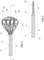
- Figure 1 shows a connection element 12 according to the present invention.
- connection element 12 is made of composite material comprising a bundle of fibres 14 and a binding agent.
- connection element 12 comprises an insertion portion 16 having two ends 18, 20.
- the insertion portion 16 comprises a section of the bundle of fibres embedded in the binding agent to form a monolithic structure.
- a fixing portion 22, 24 is provided at at least one of the ends 18, 20.
- the fixing portion 22, 24 comprises fibres 14 overhanging from the insertion portion 16 and therefore partially embedded in the monolithic structure.
- the fibres 14 of the fixing portion 22, 24 are predisposed with anchorage means 26, 28 adapted to realize an anchorage between the fibres 14 of the fixing portion 22, 24 and a plaster and/or a reinforcement element and/or a binding agent-based matrix.
- the fibres 14 in the fixing portion 22, 24 have been embedded in the binding agent and then released.
- the fibres 14 in said fixing portion 22, 24 may be virgin or at least partially virgin.
- virgin fibres means fibres and/or portions thereof which have not been embedded in the resin.
- virgin fibres may also be defined as dry fibres.
- virgin fibres are fibres and/or portions thereof which have not been resin-embedded to form a monolithic structure.
- the bundle of fibres may comprise synthetic organic fibres, natural organic fibres, inorganic fibres, and/or metallic fibres.
- these may comprise, for example, aramid fibres, poly-para-phenyl benzobisoxazole (PBO), and/or polyester.
- Natural organic fibres may comprise, for example: cotton, hemp, flax, sisal, etc.
- the inorganic fibres may comprise, for example: glass, carbon, basalt, etc.
- the metallic fibres may comprise, for example: stainless steel, carbon steel, copper, brass.
- the bundle of fibres may comprise fibres of different types in the same bundle.
- the binding agent may be, for example, an organic or inorganic resin.
- thermosetting resin this may be of the thermosetting or thermoplastic type.
- thermosetting resin it may be chosen, for example, from the group comprising vinyl-ester resins, poly-ester resins, bisphenol resins, epoxy resins, etc.
- the fibres may be treated with surface additives to improve the durability thereof and the adhesion thereof with the resin and/or the matrix, which may be organic, inorganic or of another type.
- the insertion portion 16 which in use is inserted inside a hole in the masonry, may have an outer surface with quartz sand and resin fillings, or an outer surface subjected to roughening by means of a mechanical processing or application of material.
- the length of the insertion portion 16 may range from 10 mm to 20000 mm.
- the length of the insertion portion 16 may be decided based on the thickness of the structural or non-structural element in which it must be inserted.
- the insertion portion 16 may have a substantially circular, rectangular, or square cross-section or a cross-section according to design specifications.
- the insertion portion 16 may be hollow for geotechnical or structural applications in general, in order to facilitate any filling through the inner volume of the connector (injection of grout or structural materials which are primordially fluid or semi-fluid).
- the diameter of the insertion portion 16 may range from 1 mm to 150 mm.
- the fixing portion 22, 24 may be arranged at one or both ends 18, 20 of the insertion portion.
- the length of the fixing portion 22, 24 may range from 10 mm to 20000 mm.
- such fibres 14 of the fixing portion 22, 24 may be, for example, preliminarily primed or soaked in an organic or inorganic matrix and/or a matrix of another type in order to improve the mechanical behaviour thereof.
- the anchorage means 26, 28 may be arranged in a position distal with respect to the insertion portion (16).
- the anchorage means 26, 28 may comprise, for example, spherical, circular, cylindrical, drop-like, polyhedral shapes.
- anchorage means 26, 28 may also have generic shapes.
- the surface of the anchorage means 26, 28 may be smooth or rough, to allow an adequate chemical and/or mechanical collaboration with the structural or non-structural element on which it is connected/inserted.
- the anchorage means 26, 28 may be made of different materials depending on the purposes.
- they may be made of polymeric, binding, metallic material, etc.
- the anchorage means may also be made of wood.
- the fixing portion 22, 24 comprises fibres 14 which may be folded so that the end thereof may also be spliced with at least one fibre 14 close to the insertion portion 16.
- the junction may be made both in a continuous production line as well as, in a second step, for example, by crimping with plastic and/or metal rings, manual and/or automatic gluing.
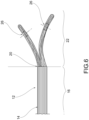
- the fixing portion 22, 24 may be substantially flat, as in the previous case, but it may comprise two superimposed branches 221, 222.
- the two branches 221, 222 may be spread apart from each other according to two different directions, as shown in the example of Figure 6 .
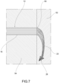
- the insertion portion 16 is inserted inside a hole made in the structural and/or non-structural element, and the fixing portion 22, 24 is bent towards the masonry and embedded in the plaster so that the anchorage means 26, 28 exert an additional anchoring action with respect to that exerted only by the fibres of the prior art, when immersed in a matrix.
- connection element 12 out of composite material comprising fibres 14 and a resin-based binding agent according to the present invention.
- the method comprises the steps of:
- the cutting may occur at a section of the bundle of fibres impregnated with resin, or at a section of the bundle of fibres 14 in which the fibres 14 comprise or consist of virgin fibres.
- connection element 12 may comprise the steps of:
- the step of impregnating with the binding agent may involve only some sections of the fibres, i.e., those which will constitute the insertion portion 16 of the connection element 12.
- the portions of the fibres which will form the fixing portions will be of the virgin type.
- the method for consolidating a masonry 54 with a connection element 12 of the present invention essentially comprises the steps of:
- the method may comprise a step in which a reinforcement mesh is provided on the surface of the masonry.
- the present invention also relates to an installation kit comprising an insertion funnel 40 adapted to facilitate the insertion of the connection element 12 inside a hole in a masonry.
- the insertion funnel 40 may also be used to guide the virgin fibres of the fixing portion at the curving area on the surface of the structural and/or non-structural element.
- the insertion funnel 40 may comprise a tubular portion 44, adapted to be inserted inside a hole, and a diverging portion.
- the insertion funnel 40 may be useful for positioning the fixing portions 22, 24 in order to improve the mechanical behaviour of the connection element, for example, by improving and increasing the extraction force.
- connection element according to the present invention with the related installation method and with the installation kit are therefore now evident.
- connection element which may be used to connect two plate-like resistant elements through a hole in a structural and/or non-structural element.
- the ends of the connector are both provided with a fixing portion.
- an anchorage is obtained, effectively ensuring a better performance of the tensile connector.
- connection element according to the present invention may be used, for example, as a connection system between reinforcement elements for the wall/resistant element which is required to increase the performance by means of a symmetrical or partially symmetrical reinforcement layout.
- the connector also acts as a tie rod, bracing and/or nail for geotechnics or slope stabilization (geotechnical works in general), the dry terminals/free ends thereof being possibly made on site with any geometric shape, by means of pre-moulding in the factory or direct pre-application on site, with or without the application of a mat to facilitate the creation of a junction plate or finally by providing a light primer already in the production step to improve the application steps, with the bracing and/or tie rod elements.
- bracket or reinforcement in general, continuous or discontinuous, for structural or non-structural elements in reinforced concrete, completing the construction steps in the factory (co-moulding or similar techniques) or on site.
- the particular production method allows to manufacture a product which maintains the mechanical resistance and stiffness properties of the connection in the anchorage area of the elements to be connected unaltered.
Landscapes
- Engineering & Computer Science (AREA)
- Architecture (AREA)
- Civil Engineering (AREA)
- Structural Engineering (AREA)
- Chemical & Material Sciences (AREA)
- Chemical Kinetics & Catalysis (AREA)
- Electrochemistry (AREA)
- Mechanical Engineering (AREA)
- Joining Of Building Structures In Genera (AREA)
- Reinforcement Elements For Buildings (AREA)
Applications Claiming Priority (3)
| Application Number | Priority Date | Filing Date | Title |
|---|---|---|---|
| IT102019000024499A IT201900024499A1 (it) | 2019-12-18 | 2019-12-18 | Elemento di connessione per l’edilizia, procedimento per il consolidamento di un elemento strutturale e non strutturale, e relativo kit di installazione |
| PCT/IB2020/062098 WO2021124190A1 (en) | 2019-12-18 | 2020-12-17 | Connection element for the building industry, method for consolidating a structural and non-structural element, and related installation kit |
| EP20839392.6A EP4077830B1 (de) | 2020-12-17 | Verbindungselement für die bauindustrie, verfahren zur konsolidierung eines struktur- und nichtstrukturelements und dazugehöriges installationskit |
Related Parent Applications (2)
| Application Number | Title | Priority Date | Filing Date |
|---|---|---|---|
| EP20839392.6A Division EP4077830B1 (de) | 2019-12-18 | 2020-12-17 | Verbindungselement für die bauindustrie, verfahren zur konsolidierung eines struktur- und nichtstrukturelements und dazugehöriges installationskit |
| EP20839392.6A Division-Into EP4077830B1 (de) | 2019-12-18 | 2020-12-17 | Verbindungselement für die bauindustrie, verfahren zur konsolidierung eines struktur- und nichtstrukturelements und dazugehöriges installationskit |
Publications (2)
| Publication Number | Publication Date |
|---|---|
| EP4553251A2 true EP4553251A2 (de) | 2025-05-14 |
| EP4553251A3 EP4553251A3 (de) | 2025-05-21 |
Family
ID=70155122
Family Applications (1)
| Application Number | Title | Priority Date | Filing Date |
|---|---|---|---|
| EP25166711.9A Pending EP4553251A3 (de) | 2019-12-18 | 2020-12-17 | Verbindungselement für die bauindustrie, verfahren zum konsolidieren eines strukturellen und nichtstrukturellen elements und zugehöriges installationskit |
Country Status (5)
| Country | Link |
|---|---|
| US (1) | US20230015704A1 (de) |
| EP (1) | EP4553251A3 (de) |
| CA (1) | CA3165268A1 (de) |
| IT (1) | IT201900024499A1 (de) |
| WO (1) | WO2021124190A1 (de) |
Family Cites Families (20)
| Publication number | Priority date | Publication date | Assignee | Title |
|---|---|---|---|---|
| US3422586A (en) * | 1966-05-12 | 1969-01-21 | Domenico Parma | System for post-stressing concrete slabs,beams or other structures |
| US5567374A (en) * | 1991-11-01 | 1996-10-22 | Applied Research Of Australia, Pty. Ltd. | Polymeric moldings reinforced with tows of fibers |
| US6324940B1 (en) * | 1997-08-13 | 2001-12-04 | Maclean-Fogg Company | Composite link |
| US7207149B2 (en) * | 2002-07-24 | 2007-04-24 | Fyfe Edward R | Anchor and method for reinforcing a structure |
| US7980033B1 (en) * | 2002-07-24 | 2011-07-19 | Fyfe Co. Llc | System and method for increasing the shear strength of a structure |
| US7574840B1 (en) * | 2002-07-24 | 2009-08-18 | Fyfe Co., Llc | Connector for reinforcing the attachment among structural components |
| KR100438664B1 (ko) * | 2003-09-09 | 2004-07-02 | (유)한국기계 | 강화섬유앵커를 이용하여 강화섬유시트로 구조물을보강하는 공법 |
| ITRM20050066A1 (it) * | 2005-02-17 | 2006-08-18 | Tec Inn S R L | Metodo per rinforzare strutture edili e rivestimento ottenuto da tale metodo. |
| DE102006058377B4 (de) * | 2006-12-08 | 2010-09-16 | Airbus Deutschland Gmbh | Stange zur strukturellen Verstärkung einer Rumpfstruktur eines Flugzeugs |
| US7946088B1 (en) * | 2009-01-22 | 2011-05-24 | Fyfe Edward R | System for reinforcing structure using site-customized materials |
| FR2948712B1 (fr) * | 2009-08-03 | 2015-03-06 | Soletanche Freyssinet | Procede de renforcement d'une structure de construction, et ouvrage ainsi renforce |
| US8496404B1 (en) * | 2010-08-24 | 2013-07-30 | Fyfe Co., Llc | Reinforcement system for increased lateral stability of flood wall |
| EP2439359A1 (de) * | 2010-10-06 | 2012-04-11 | F.J. Aschwanden AG | Verfahren zum Verstärken von betonierten Platten im Bereich von Stützelementen |
| US9194140B2 (en) * | 2010-11-04 | 2015-11-24 | Garland Industries, Inc. | Method and apparatus for repairing concrete |
| US8584431B2 (en) * | 2011-01-13 | 2013-11-19 | Robert Luke Secrest | Carbon fiber wall reinforcement system and a method for its use |
| US9784004B2 (en) * | 2014-08-19 | 2017-10-10 | Kulstoff Composite Products, LLC | Fiber reinforced anchors and connectors, methods of making anchors and connectors, and processes for reinforcing a structure |
| DE102015203511A1 (de) * | 2015-02-27 | 2016-09-01 | C-Con GmbH & Co. KG | Befestigungsstange zum Befestigen von Anbauteilen an einem Mauerwerk oder einem Betonkörper |
| ITVI20150072A1 (it) * | 2015-03-16 | 2016-09-16 | Carbonveneta Tecnologia Nei Compositi S R L | Procedimento per la realizzazione di un connettore del tipo cosiddetto a "fiocco" |
| US11242690B2 (en) * | 2018-01-19 | 2022-02-08 | Titcomb Brothers Manufacturing, Inc. | Loop tie for concrete forming panel systems |
| IT201900024511A1 (it) * | 2019-12-18 | 2021-06-18 | Fibre Net Holding S R L | Elemento di connessione, procedimento per la fabbricazione di un elemento di connessione e relativo kit di installazione |
-
2019
- 2019-12-18 IT IT102019000024499A patent/IT201900024499A1/it unknown
-
2020
- 2020-12-17 EP EP25166711.9A patent/EP4553251A3/de active Pending
- 2020-12-17 US US17/787,170 patent/US20230015704A1/en not_active Abandoned
- 2020-12-17 CA CA3165268A patent/CA3165268A1/en active Pending
- 2020-12-17 WO PCT/IB2020/062098 patent/WO2021124190A1/en not_active Ceased
Also Published As
| Publication number | Publication date |
|---|---|
| IT201900024499A1 (it) | 2021-06-18 |
| WO2021124190A1 (en) | 2021-06-24 |
| EP4077830A1 (de) | 2022-10-26 |
| CA3165268A1 (en) | 2021-06-24 |
| EP4553251A3 (de) | 2025-05-21 |
| US20230015704A1 (en) | 2023-01-19 |
Similar Documents
| Publication | Publication Date | Title |
|---|---|---|
| US7056463B2 (en) | Method of manufacturing prestressed concrete | |
| US5613334A (en) | Laminated composite reinforcing bar and method of manufacture | |
| US11268280B2 (en) | Anchorage of continuous fiber-reinforced polymer strands | |
| US11555310B2 (en) | Composite rebar | |
| EP4553250A2 (de) | Verbindungselement, verfahren zur herstellung eines verbindungselements und zugehöriges installationskit | |
| DE102008040919A1 (de) | Verfahren zur Herstellung eines Betonbauteiles mit einer polymergetränkten textilen Bewehrung sowie Betonbauteil mit einer polymergetränkten textilen Bewehrung | |
| EP4077830B1 (de) | Verbindungselement für die bauindustrie, verfahren zur konsolidierung eines struktur- und nichtstrukturelements und dazugehöriges installationskit | |
| EP4553251A2 (de) | Verbindungselement für die bauindustrie, verfahren zum konsolidieren eines strukturellen und nichtstrukturellen elements und zugehöriges installationskit | |
| CN104929320A (zh) | 一种钢筋连接结构及其施工方法 | |
| KR102004420B1 (ko) | V형 띠철근을 이용한 기둥 보강 방법 | |
| JP2000054561A (ja) | 強化繊維シートによるコンクリート構造物の補強方法 | |
| US20080313907A1 (en) | Method For Reinforcing a Metal Tubular Structure | |
| EP0386387B1 (de) | Flächenhafte Grenzschichtverbindung und Verfahren zu deren Herstellung | |
| JP4020005B2 (ja) | 繊維強化樹脂製補強材を用いた補強構造及び補強方法 | |
| Young-Jun et al. | Tensile Strength of GFRP reinforcing Bars with Hollow section | |
| JPH0555676B2 (de) | ||
| JP2007514077A (ja) | 構成要素 | |
| AU2021104691A4 (en) | FRP reinforcement bar with improved recycled glass coating | |
| HU186805B (en) | Load-bearing casing surface for supporting structures | |
| RU2644370C1 (ru) | Способ соединения композитных стержней | |
| DE102013009338A1 (de) | Verfahren zum Herstellen eines schüttfähigen und verfestigbaren Baustoffes und ein solcher Baustoff | |
| JPH09105207A (ja) | 緊張材の定着具 | |
| JPH0751820B2 (ja) | 繊維強化樹脂複合体製緊張材 | |
| WO2005085545A1 (de) | Bewehrungsstab für mineralische baustoffe |
Legal Events
| Date | Code | Title | Description |
|---|---|---|---|
| PUAI | Public reference made under article 153(3) epc to a published international application that has entered the european phase |
Free format text: ORIGINAL CODE: 0009012 |
|
| REG | Reference to a national code |
Ref country code: DE Ref legal event code: R079 Free format text: PREVIOUS MAIN CLASS: E04G0023020000 Ipc: E04C0005070000 |
|
| STAA | Information on the status of an ep patent application or granted ep patent |
Free format text: STATUS: THE APPLICATION HAS BEEN PUBLISHED |
|
| PUAL | Search report despatched |
Free format text: ORIGINAL CODE: 0009013 |
|
| AC | Divisional application: reference to earlier application |
Ref document number: 4077830 Country of ref document: EP Kind code of ref document: P |
|
| AK | Designated contracting states |
Kind code of ref document: A2 Designated state(s): AL AT BE BG CH CY CZ DE DK EE ES FI FR GB GR HR HU IE IS IT LI LT LU LV MC MK MT NL NO PL PT RO RS SE SI SK SM TR |
|
| AK | Designated contracting states |
Kind code of ref document: A3 Designated state(s): AL AT BE BG CH CY CZ DE DK EE ES FI FR GB GR HR HU IE IS IT LI LT LU LV MC MK MT NL NO PL PT RO RS SE SI SK SM TR |
|
| RIC1 | Information provided on ipc code assigned before grant |
Ipc: E04G 23/02 20060101ALI20250411BHEP Ipc: E04C 5/07 20060101AFI20250411BHEP |
|
| STAA | Information on the status of an ep patent application or granted ep patent |
Free format text: STATUS: REQUEST FOR EXAMINATION WAS MADE |