EP4553236A1 - Construction machine - Google Patents
Construction machine Download PDFInfo
- Publication number
- EP4553236A1 EP4553236A1 EP23930552.7A EP23930552A EP4553236A1 EP 4553236 A1 EP4553236 A1 EP 4553236A1 EP 23930552 A EP23930552 A EP 23930552A EP 4553236 A1 EP4553236 A1 EP 4553236A1
- Authority
- EP
- European Patent Office
- Prior art keywords
- cooling
- fuel cell
- hydrogen
- hydrogen tank
- heat exchanger
- Prior art date
- Legal status (The legal status is an assumption and is not a legal conclusion. Google has not performed a legal analysis and makes no representation as to the accuracy of the status listed.)
- Pending
Links
Images





Classifications
-
- E—FIXED CONSTRUCTIONS
- E02—HYDRAULIC ENGINEERING; FOUNDATIONS; SOIL SHIFTING
- E02F—DREDGING; SOIL-SHIFTING
- E02F9/00—Component parts of dredgers or soil-shifting machines, not restricted to one of the kinds covered by groups E02F3/00 - E02F7/00
- E02F9/08—Superstructures; Supports for superstructures
- E02F9/0858—Arrangement of component parts installed on superstructures not otherwise provided for, e.g. electric components, fenders, air-conditioning units
- E02F9/0866—Engine compartment, e.g. heat exchangers, exhaust filters, cooling devices, silencers, mufflers, position of hydraulic pumps in the engine compartment
-
- E—FIXED CONSTRUCTIONS
- E02—HYDRAULIC ENGINEERING; FOUNDATIONS; SOIL SHIFTING
- E02F—DREDGING; SOIL-SHIFTING
- E02F3/00—Dredgers; Soil-shifting machines
- E02F3/04—Dredgers; Soil-shifting machines mechanically-driven
- E02F3/28—Dredgers; Soil-shifting machines mechanically-driven with digging tools mounted on a dipper- or bucket-arm, i.e. there is either one arm or a pair of arms, e.g. dippers, buckets
- E02F3/30—Dredgers; Soil-shifting machines mechanically-driven with digging tools mounted on a dipper- or bucket-arm, i.e. there is either one arm or a pair of arms, e.g. dippers, buckets with a dipper-arm pivoted on a cantilever beam, i.e. boom
- E02F3/32—Dredgers; Soil-shifting machines mechanically-driven with digging tools mounted on a dipper- or bucket-arm, i.e. there is either one arm or a pair of arms, e.g. dippers, buckets with a dipper-arm pivoted on a cantilever beam, i.e. boom working downwardly and towards the machine, e.g. with backhoes
-
- E—FIXED CONSTRUCTIONS
- E02—HYDRAULIC ENGINEERING; FOUNDATIONS; SOIL SHIFTING
- E02F—DREDGING; SOIL-SHIFTING
- E02F9/00—Component parts of dredgers or soil-shifting machines, not restricted to one of the kinds covered by groups E02F3/00 - E02F7/00
- E02F9/08—Superstructures; Supports for superstructures
- E02F9/0858—Arrangement of component parts installed on superstructures not otherwise provided for, e.g. electric components, fenders, air-conditioning units
- E02F9/0883—Tanks, e.g. oil tank, urea tank, fuel tank
-
- E—FIXED CONSTRUCTIONS
- E02—HYDRAULIC ENGINEERING; FOUNDATIONS; SOIL SHIFTING
- E02F—DREDGING; SOIL-SHIFTING
- E02F9/00—Component parts of dredgers or soil-shifting machines, not restricted to one of the kinds covered by groups E02F3/00 - E02F7/00
- E02F9/16—Cabins, platforms, or the like, for drivers
-
- E—FIXED CONSTRUCTIONS
- E02—HYDRAULIC ENGINEERING; FOUNDATIONS; SOIL SHIFTING
- E02F—DREDGING; SOIL-SHIFTING
- E02F9/00—Component parts of dredgers or soil-shifting machines, not restricted to one of the kinds covered by groups E02F3/00 - E02F7/00
- E02F9/20—Drives; Control devices
- E02F9/2058—Electric or electro-mechanical or mechanical control devices of vehicle sub-units
- E02F9/2062—Control of propulsion units
-
- E—FIXED CONSTRUCTIONS
- E02—HYDRAULIC ENGINEERING; FOUNDATIONS; SOIL SHIFTING
- E02F—DREDGING; SOIL-SHIFTING
- E02F9/00—Component parts of dredgers or soil-shifting machines, not restricted to one of the kinds covered by groups E02F3/00 - E02F7/00
- E02F9/24—Safety devices, e.g. for preventing overload
-
- E—FIXED CONSTRUCTIONS
- E02—HYDRAULIC ENGINEERING; FOUNDATIONS; SOIL SHIFTING
- E02F—DREDGING; SOIL-SHIFTING
- E02F9/00—Component parts of dredgers or soil-shifting machines, not restricted to one of the kinds covered by groups E02F3/00 - E02F7/00
- E02F9/26—Indicating devices
-
- G—PHYSICS
- G05—CONTROLLING; REGULATING
- G05D—SYSTEMS FOR CONTROLLING OR REGULATING NON-ELECTRIC VARIABLES
- G05D23/00—Control of temperature
- G05D23/19—Control of temperature characterised by the use of electric means
- G05D23/1927—Control of temperature characterised by the use of electric means using a plurality of sensors
-
- H—ELECTRICITY
- H01—ELECTRIC ELEMENTS
- H01M—PROCESSES OR MEANS, e.g. BATTERIES, FOR THE DIRECT CONVERSION OF CHEMICAL ENERGY INTO ELECTRICAL ENERGY
- H01M8/00—Fuel cells; Manufacture thereof
- H01M8/04—Auxiliary arrangements, e.g. for control of pressure or for circulation of fluids
- H01M8/04007—Auxiliary arrangements, e.g. for control of pressure or for circulation of fluids related to heat exchange
-
- H—ELECTRICITY
- H01—ELECTRIC ELEMENTS
- H01M—PROCESSES OR MEANS, e.g. BATTERIES, FOR THE DIRECT CONVERSION OF CHEMICAL ENERGY INTO ELECTRICAL ENERGY
- H01M8/00—Fuel cells; Manufacture thereof
- H01M8/04—Auxiliary arrangements, e.g. for control of pressure or for circulation of fluids
- H01M8/04082—Arrangements for control of reactant parameters, e.g. pressure or concentration
- H01M8/04201—Reactant storage and supply, e.g. means for feeding, pipes
- H01M8/04208—Cartridges, cryogenic media or cryogenic reservoirs
-
- H—ELECTRICITY
- H01—ELECTRIC ELEMENTS
- H01M—PROCESSES OR MEANS, e.g. BATTERIES, FOR THE DIRECT CONVERSION OF CHEMICAL ENERGY INTO ELECTRICAL ENERGY
- H01M8/00—Fuel cells; Manufacture thereof
- H01M8/04—Auxiliary arrangements, e.g. for control of pressure or for circulation of fluids
- H01M8/04298—Processes for controlling fuel cells or fuel cell systems
- H01M8/04313—Processes for controlling fuel cells or fuel cell systems characterised by the detection or assessment of variables; characterised by the detection or assessment of failure or abnormal function
- H01M8/0444—Concentration; Density
- H01M8/04447—Concentration; Density of anode reactants at the inlet or inside the fuel cell
-
- B—PERFORMING OPERATIONS; TRANSPORTING
- B60—VEHICLES IN GENERAL
- B60Y—INDEXING SCHEME RELATING TO ASPECTS CROSS-CUTTING VEHICLE TECHNOLOGY
- B60Y2200/00—Type of vehicle
- B60Y2200/40—Special vehicles
- B60Y2200/41—Construction vehicles, e.g. graders, excavators
- B60Y2200/412—Excavators
-
- H—ELECTRICITY
- H01—ELECTRIC ELEMENTS
- H01M—PROCESSES OR MEANS, e.g. BATTERIES, FOR THE DIRECT CONVERSION OF CHEMICAL ENERGY INTO ELECTRICAL ENERGY
- H01M2250/00—Fuel cells for particular applications; Specific features of fuel cell system
- H01M2250/20—Fuel cells in motive systems, e.g. vehicle, ship, plane
-
- Y—GENERAL TAGGING OF NEW TECHNOLOGICAL DEVELOPMENTS; GENERAL TAGGING OF CROSS-SECTIONAL TECHNOLOGIES SPANNING OVER SEVERAL SECTIONS OF THE IPC; TECHNICAL SUBJECTS COVERED BY FORMER USPC CROSS-REFERENCE ART COLLECTIONS [XRACs] AND DIGESTS
- Y02—TECHNOLOGIES OR APPLICATIONS FOR MITIGATION OR ADAPTATION AGAINST CLIMATE CHANGE
- Y02E—REDUCTION OF GREENHOUSE GAS [GHG] EMISSIONS, RELATED TO ENERGY GENERATION, TRANSMISSION OR DISTRIBUTION
- Y02E60/00—Enabling technologies; Technologies with a potential or indirect contribution to GHG emissions mitigation
- Y02E60/30—Hydrogen technology
- Y02E60/50—Fuel cells
Definitions
- the present disclosure relates to a construction machine such as a hydraulic excavator including a fuel cell system.
- a fuel cell system is configured to include a fuel cell generating power supplied to an electric motor serving as a power source of a construction machine and a hydrogen tank storing hydrogen supplied to the fuel cell (see Patent Document 1).
- a hydrogen gas needs to be filled into the hydrogen tank, using a vehicle with hydrogen supply equipment (mobile hydrogen supply equipment), for example.
- vehicle with hydrogen supply equipment mobile hydrogen supply equipment
- the vehicle with the hydrogen supply equipment is moved to be close to the construction machine and a new hydrogen gas is filled into the hydrogen tank, with a filling nozzle of the hydrogen supply equipment connected to the hydrogen tank.
- hydrogen gas can be stably supplied to a fuel cell of a construction machine that is operated at a working site.
- Patent Document 1 Japanese Patent Laid-Open No. 2022-180565 A
- leakage of hydrogen gas can occur due to abnormal operations in the hydrogen supply equipment or defective filling work of hydrogen, thereby allowing the hydrogen gas to be stagnant around the hydrogen tank.
- the hydrogen gas stagnant around the hydrogen tank is preferably discharged so as to be swiftly swept away from an operator's seat.
- a construction machine has a self-propelled vehicle body, wherein the vehicle body includes: an operator' s seat; a fuel cell generating power supplied to an electric motor; a hydrogen tank storing hydrogen supplied to the fuel cell; a heat exchanger cooling the fuel cell; and a cooling fan supplying a cooling air to the heat exchanger, characterized in that the operator's seat is disposed on the upstream side of the hydrogen tank with respect to a flow direction of the cooling air generated by the cooling fan.
- the hydrogen gas that is present around the hydrogen tank can be discharged so as to be swiftly swept away from the operator's seat, using the cooling air flowing from the operator's seat to the hydrogen tank.
- a construction machine by taking the case of a hydraulic excavator, will be explained in detail with reference to Figs. 1 to 10 .
- the running direction of a hydraulic excavator is defined as front-and-rear direction
- the direction perpendicular to the running direction of the hydraulic excavator is defined as right-and-left direction.
- FIGs. 1 to 6 illustrates a construction machine according to a first embodiment of the present invention.
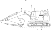
- a hydraulic excavator 1 as a typical construction machine, includes a self-propelled crawler type lower traveling structure 2 and an upper revolving structure 3 mounted rotatably on the lower traveling structure 2.
- a vehicle body of the hydraulic excavator 1 is configured by the lower traveling structure 2 and the upper revolving structure 3.
- the hydraulic excavator 1 includes an electric motor 14 as a power source, a fuel cell 11 generating power supplied to the electric motor 14, and a hydrogen tank 20 storing hydrogen supplied to the fuel cell 11.
- the upper revolving structure 3 is mounted rotatably on the lower traveling structure 2 with a revolving device 4 in between.
- the upper revolving structure 3 has a revolving frame 5 that constitutes a base.
- the revolving frame 5 is configured to include a center frame 5A located at a center portion in the right-and-left direction, a left side frame 5B and a right side frame 5C disposed on the left and right sides across the center frame 5A.
- a working mechanism 6 excavating earth and sand, etc. is mounted on the front end side of the revolving frame 5.
- a counterweight 7 taking a weight balance with the working device 6 is provided on the rear end side of the revolving frame 5.
- An exhaust port 7A is formed on a rear surface of the counterweight 7.
- a cab 8 forming an operator's room is provided on the front left side of the revolving frame 5.
- An operator's seat 9 for an on-board operator to be seated, a traveling lever device, an operating lever device or the like operated by the operator (each not shown) are provided in the cab 8.
- An exterior cover 10 is provided on the revolving frame 5 to be located forward of the counterweight 7.
- the later-described fuel cell 11, the electric motor 14, a hydraulic pump 16, the hydrogen tank 20, a heat exchanger 24 and the like are accommodated within the exterior cover 10.
- the exterior cover 10 has a left surface 10A, a right surface 10B and an upper surface 10C.
- An air flow opening 10D communicating the inside and the outside of the exterior cover 10 is formed on the left surface 10A and the right surface 10B.
- An upper cover 10E is provided on the upper surface 10C, covering a hydrogen tank 20, a heat exchanger 24 and the like protruding upward from the upper surface 10C.
- the fuel cell 11 is located rearward of the cab 8 and mounted on the revolving frame 5.
- the fuel cell 11 constitutes a fuel cell system together with a PCU (Power Control Unit) and an auxiliary machine such as a supercharger (each not shown), for example.
- the fuel cell 11 generates power supplied to the electric motor 14, using hydrogen supplied from the hydrogen tank 20.
- a battery (secondary battery) 12 is mounted on the revolving frame 5 to be adjacent to the left side of the fuel cell 11.
- the battery 12 stores power in excess of the power supplied to the electric motor 14 of the power generated by the fuel cell 11, for example.
- the fuel cell 11 and the battery 12 are connected via a high-voltage cable 13.
- the electric motor 14 is adjacent to the right side of the fuel cell 11 and mounted at a central portion of the revolving frame 5 in the right-and-left direction.
- An inverter 15 is connected to the electric motor 14 via the high-voltage cable 13.
- the inverter 15 is connected to the fuel cell 11 via the high-voltage cable 13.
- the inverter 15 converts the direct current power supplied from the fuel cell 11 or the battery 12 into the alternating current power to be supplied to the electric motor 14 to control the rotation of the electric motor 14.
- the hydraulic pump 16 is adjacent to the right side of the electric motor 14 and mounted on the revolving frame 5.
- the hydraulic pump 16 is driven by the electric motor 14 to pressurize and discharge the hydraulic oil reserved in a hydraulic oil tank (not shown).
- a control valve 17 is mounted on the right front side of the revolving frame 5.
- the control valve 17 is connected to each type of hydraulic actuator mounted on the hydraulic excavator 1 and the hydraulic pump 16 via hydraulic lines (not shown) to selectively supply the hydraulic oil (pressurized oil) discharged from the hydraulic pump 16 to each of the hydraulic actuators.
- a DC/DC converter 18 is connected to the fuel cell 11 via the high-voltage cable 13 and connected to later-described cooling fans 25C, 25D, 26A, 27A via a cable 19.
- the DC/DC converter 18 converts the direct current power supplied from the fuel cell 11 or the battery 12 into the voltage corresponding to the cooling fans 25C, 25D, 26A, 27A in response to a control signal from a later-described controller 36.
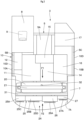
- the plurality of hydrogen tanks (hydrogen storage vessel) 20 is located to be surrounded by the fuel cell 11, the electric motor 14 and the counterweight 7 and disposed on the rear side of the revolving frame 5.
- the hydrogen tank 20 is composed of a cylindrical container excellent in pressure resistance and disposed to extend in the right-and-left direction of the revolving frame 5. Compressed, high-pressure hydrogen gas is stored within the hydrogen tank 20.
- a rack 21 is fixed on the rear side of the revolving frame 5, and the plurality of hydrogen tanks 20 is held to be aligned in the vertical direction by the rack 21.
- the hydrogen tank 20 and the fuel cell 11 are connected via a hydrogen gas line 22, and a hydrogen valve 23 is provided in the course of the hydrogen gas line 22.
- the hydrogen valve 23 opens and closes the hydrogen gas line 22 in response to a control signal from the controller 36, and controls the supply of hydrogen gas from the hydrogen tank 20 to the fuel cell 11.
- a vehicle including hydrogen supply equipment, for example, is moved to be close to the hydraulic excavator 1 and a filling nozzle of the hydrogen supply equipment is connected to the hydrogen tank 20.
- This configuration allows for filling of compressed hydrogen gas into the hydrogen tank 20 to stably supply hydrogen gas to the fuel cell 11 mounted on the hydraulic excavator 1.
- the heat exchanger 24 is located between the counterweight 7 and the hydrogen tank 20 and mounted rearward of the revolving frame 5.
- the heat exchanger 24 is configured to include a radiator for fuel cell 25, a radiator for motor and inverter 26 and an oil cooler 27.
- the radiator for fuel cell 25, the radiator for motor and inverter 26 and the oil cooler 27 are disposed to be aligned in the right-and-left direction of the revolving frame 5 and face outward of the upper revolving structure 3 through the exhaust port 7A of the counterweight 7.
- the mounting of the heat exchanger 24 rearward of the revolving frame 5 allows devices required for regular maintenance such as the battery 12 or an oil filter (not shown) to be disposed near the left surface 10A and the right surface 10B of the exterior cover 10. This configuration can improve the maintainability of these devices.
- the radiator for fuel cell 25 is disposed rearward of the fuel cell 11.
- the radiator for fuel cell 25 is connected to the fuel cell 11 and a cooling water circulation path (not shown) provided in an auxiliary machine (e.g., PCU, supercharger) incorporated in the fuel cell 11 via a cooling water passage 28.
- the radiator for fuel cell 25 is configured by the connection of 2 cooling units 25A, 25B.
- Two cooling fans 25C, 25D are mounted on the rear side of the radiator for fuel cell 25. The cooling fans 25C, 25D are rotated to allow an outdoor air to flow into the exterior cover 10 through the air flow opening 10D formed on the left surface 10A and the right surface 10B of the exterior cover 10.
- the outdoor air is collected within the exterior cover 10 and then turns into a cooling air F1 represented by a solid arrow moving from the front side (the operator's seat 9 side) to the rear side (the hydrogen tank 20 side) of the revolving frame 5.
- the cooling air F1 is discharged outward of the upper revolving structure 3 (the exterior cover 10) through the exhaust port 7A of the counterweight 7.
- the heat released from the radiator for fuel cell 25 is transferred into the cooling air F1 to cool the fuel cell 11 and the auxiliary machine.
- the cooling fans 25C, 25D each composed of an electrically driven fan, the rotating direction and the rotational speed are controlled in response to a control signal from the controller 36.
- the radiator for motor and inverter 26 is disposed rearward of the electric motor 14.
- the radiator for motor and inverter 26 is connected to a cooling water circulation path (not shown) provided in the electric motor 14 and the inverter 15 via a cooling water passage 29.
- a cooling fan 26A composed of an electrically driven fan is mounted on the rear side of the radiator for motor and inverter 26. The heat released from the radiator for motor and inverter 26 and transferred into the cooling air F1 generated by the rotation of the cooling fan 26A cools the electric motor 14 and the inverter 15.
- the oil cooler 27 is disposed rearward of the hydraulic pump 16.
- the oil cooler 27 is connected to a hydraulic circuit to which the hydraulic pump 16 and the control valve 17 are connected via a hydraulic passage 30.
- the cooling fan 27A composed of an electrically driven fan is mounted on the rear side of the oil cooler 27. The heat released from hydraulic oil (return oil) returning from the hydraulic actuator to a hydraulic oil tank (not shown) and transferred into the cooling air F1 generated by the rotation of the cooling fan 27A cools the hydraulic oil.
- a shroud 31 is provided between the hydrogen tank 20 and the heat exchanger 24.
- the shroud 31 is formed of a cylindrical body having a width dimension equivalent to the hydrogen tank 20 in the right-and-left direction of the revolving frame 5.
- the shroud 31 forms a passage for the cooling air F1 between the hydrogen tank 20 and the heat exchanger 24 and introduces the cooling air F1 generated by the rotation of the cooling fans 25C, 25D, 26A, 27A to the heat exchanger 24 (the radiator for fuel cell 25, the radiator for motor and inverter 26, the oil cooler 27).
- the cooling fans 25C, 25D, 26A, 27A and the shroud 31 are disposed on the downstream side of the hydrogen tank 20 with respect to a flow direction of the cooling air F1. This configuration can reduce turbulent flow from the cooling air F1 hitting the hydrogen tank 20, rectify the flow of the cooling air F1 with the shroud 31 and efficiently supply a large amount of cooling air F1 to the heat exchanger 24.
- a hydrogen sensor 32 is located within the exterior cover 10 mounted on the revolving frame 5 and provided near the hydrogen tank 20.
- the hydrogen sensor 32 e.g., in a case where hydrogen gas leakage occurs when hydrogen gas is filled into the hydrogen tank 20, detects the concentration of the hydrogen gas stagnant around the hydrogen tank 20 and outputs a detection signal to the controller 36, depending on the concentration of the hydrogen gas.
- a temperature sensor 33 is provided in the cooling water passage 28 connected to the radiator for fuel cell 25.
- the temperature sensor 33 detects the temperature of the cooling water flowing in and out of the radiator for fuel cell 25 and outputs a detection signal to the controller 36, depending on the temperature.
- a temperature sensor 34 is provided in the cooling water passage 29 connected to the radiator for motor and inverter 26. The temperature sensor 34 detects the temperature of the cooling water flowing in and out of the radiator for motor and inverter 26 and outputs a detection signal to the controller 36, depending on the temperature.
- a temperature sensor 35 is provided in the hydraulic passage 30 connected to the oil cooler 27. The temperature sensor 35 detects the temperature of the hydraulic oil flowing in and out of the oil cooler 27 and outputs a detection signal to the controller 36, depending on the temperature of the hydraulic oil.
- the controller 36 controls the operation of the fuel cell 11, the battery 12, the inverter 15, the DC/DC converter 18, the hydrogen valve 23, and the cooling fans 25C, 25D, 26A, 27A.
- the hydrogen sensor 32, the temperature sensors 33, 34, 35 and a start key 37 are connected to the input side of the controller 36.
- the fuel cell 11, the battery 12, the inverter 15, the DC/DC converter 18, the hydrogen valve 23 and the cooling fans 25C, 25D, 26A, 27A are connected to the output side of the controller 36.
- the start key 37 is disposed in the cab 8 and operated by an operator to start the controller 36.
- the controller 36 starts the battery 12, the inverter 15, the DC/DC converter 18, the hydrogen valve 23 and the fuel cell 11.
- the controller 36 supplies control signals to the cooling fans 25C, 25D, 26A, 27A to control the operation thereof, based upon detection signals inputted from the hydrogen sensor 32 and the temperature sensors 33, 34, 35.
- the hydraulic excavator 1 of this embodiment which is configured as described above, will be operated by an operator with the start key 37 in the cab 8 to activate the controller 36. Then, the controller 36 powers the inverter 15, the battery 12, the DC/DC converter 18 and the hydrogen valve 23. Once the activation of the inverter 15, the battery 12, the DC/DC converter 18 and the hydrogen valve 23 is completed, the controller 36 starts the fuel cell 11 and thereafter a monitor (not shown) disposed in the cab 8 displays the activation completion of the fuel cell 11.
- the operator confirms the activation completion of the fuel cell 11 with the monitor, and operates keys (not shown) disposed in the cab 8.
- This operation allows for power generation in the fuel cell 11, discharge or charge in the battery 12 and driving of the electric motor 14.
- the electric motor 14 drives the hydraulic pump 16
- the hydraulic oil (pressurized oil) discharged from the hydraulic pump 16 is supplied to the control valve 17.
- the control valve 17 selectively supplies hydraulic oil to each type of hydraulic actuator, depending on the operation of a traveling lever device and an operating lever device (each not shown) provided in the cab 8.
- This mechanism allows the hydraulic excavator 1 to propel itself at a working site and revolve the upper revolving structure 3 to perform excavating work of sand and earth, using the working mechanism 6.
- the controller 36 controls the rotation of the cooling fans 25C, 25D, 26A, 27A in response to detection signals from the temperature sensors 33, 34, 35. That is, the controller 36 determines the rotational speed of the cooling fans 25C, 25D, depending on the temperature of cooling water shown by a detection signal outputted from the temperature sensor 33, determines the rotational speed of the cooling fan 26A, depending on the temperature of cooling water shown by a detection signal outputted from the temperature sensor 34 to supply control signals to the cooling fans 25C, 25D, 26A. Likewise, the controller 36 determines the rotational speed of the cooling fan 27A, depending on the temperature of hydraulic oil shown by a detection signal outputted from the temperature sensor 35 to supply a control signal to the cooling fan 27A.
- This mechanism allows the cooling fans 25C, 25D, 26A, 27A to individually rotate and the outdoor air to flow into the exterior cover 10 through the air flow opening 10D formed on the left surface 10A and the right surface 10B of the exterior cover 10.
- the outdoor air is collected within the exterior cover 10 and then turns into a cooling air F1 represented by a solid arrow moving from the front side (the operator's seat 9 side) to the rear side (the hydrogen tank 20 side) of the revolving frame 5.
- the cooling air F1 passes through the radiator for fuel cell 25, the radiator for motor and inverter 26 and the oil cooler 27 for cooling, and then will be discharged outward of the upper revolving structure 3 from the exhaust port 7A of the counterweight 7.
- This mechanism during the operation of the hydraulic excavator 1, individually controls the cooling fans 25C, 25D supplying a cooling air to the radiator for fuel cell 25, the cooling fan 26A supplying a cooling air to the radiator for motor and inverter 26 and the cooling fan 27A supplying a cooling air to the oil cooler 27.
- the hydraulic oil discharged from the fuel cell 11, the electric motor 14, the inverter 15 and the hydraulic pump 16 can be suitably cooled, depending on the respective temperatures.
- the flow direction of the cooling air F1 can be changed from the rear side to the front side of the revolving frame 5 by rotating the cooling fans 25C, 25D, 26A, 27A in reverse direction.
- a cooling air F2 represented by a dotted arrow passes through the exhaust port 7A of the counterweight 7 to flow into the exterior cover 10, and passes through the radiator for fuel cell 25, the radiator for motor and inverter 26 and the oil cooler 27, and then will be discharged outward of the upper revolving structure 3 through the air flow opening 10D formed on the left surface 10A and the right surface 10B of the exterior cover 10.
- a hydrogen gas is filled into the hydrogen tank 20 by moving a vehicle with hydrogen supply equipment (mobile hydrogen supply equipment) to be close to the hydraulic excavator 1, for example.
- compressed hydrogen gas is filled into the hydrogen tank 20, with a filling nozzle of the hydrogen supply equipment connected to the hydrogen tank 20 accommodated in the exterior cover 10.
- hydrogen gas is fully filled in the exterior cover 10 and the hydrogen gas can be stagnant around the hydrogen tank 20 until another operation of the hydraulic excavator 1 starts.
- the hydraulic excavator 1 is configured to discharge hydrogen gas outward of the upper revolving structure 3, using the cooling air F1 generated by the cooling fans 25C, 25D, 26A, 27A when the hydraulic excavator 1 in operation detects the presence of hydrogen gas around the hydrogen tank 20.
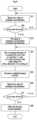
- Control processing performed by the controller 36 for detection and discharge of hydrogen gas during the operation of the hydraulic excavator 1 will be described with reference to Fig. 6 .
- the control processing is started with the start key 37 by activating the controller 36.
- the controller 36 reads out a value of hydrogen concentration around the hydrogen tank 20 (in the exterior cover 10), based upon a detection signal outputted from the hydrogen sensor 32.
- the controller 36 determines whether the value of hydrogen concentration is abnormal or not by comparison with a predetermined normal value. While the controller determines "NO” in step S2, the value judgment is repeated until the controller determines "YES” in step S2, and then in step S3, the value of hydrogen concentration is found to be abnormal.
- step S3 If the value of hydrogen concentration is found to be abnormal in step S3, any hydrogen gas is considered to be present (stagnant) around the hydrogen tank 20.
- the controller 36 supplies control signals to the cooling fans 25C, 25D, 26A, 27A in step S4, and sets rotating directions of the cooling fans 25C, 25D, 26A, 27A such that the operator's seat 9 is on the upstream side of the hydrogen tank 20 with respect to the flow direction of the cooling air.
- the rotating directions of the cooling fans 25C, 25D, 26A, 27A are set so as to generate the cooling air F1 represented by a solid arrow.
- This configuration allows the outdoor air flowing from the air flow opening 10D into the exterior cover 10 to turn into the cooling air F1 and discharged outward of the upper revolving structure 3 through the exhaust port 7A of the counterweight 7. Consequently, the hydrogen gas present around the hydrogen tank 20 can be discharged outward of the upper revolving structure 3 together with the cooling air F1.
- the operator's seat 9 provided in the cab 8 is disposed on the upstream side of the hydrogen tank 20 with respect to the flow direction of the cooling air F1. Accordingly, the hydrogen gas can be fed away from the operator's seat 9 and discharged outward of the upper revolving structure 3 not through the operator's seat 9.
- the cooling air F2 flowing through the exhaust port 7A of the counterweight 7 into the exterior cover 10 and discharged outward of the upper revolving structure 3 through the air flow opening 10D can cool the radiator for fuel cell 25, the radiator for motor and inverter 26 and the oil cooler 27.
- step S4 the controller 36 changes the rotating directions of the cooling fans 25C, 25D, 26A, 27A so as to generate the cooling air F1 in the direction opposite the cooling air F2.
- the controller 36 can set the rotating directions of the cooling fans 25C, 25D, 26A, 27A appropriately to discharge the hydrogen gas outward of the upper revolving structure 3 without allowing the gas to pass through the operator's seat 9.
- the controller 36 supplies control signals to the cooling fans 25C, 25D, 26A, 27A to increase the rotational speed of these fans.
- This mechanism allows the cooling fans 25C, 25D, 26A, 27A to be driven in constant high-speed rotation, for example, irrespective of the temperature of the cooling water and the temperature of the hydraulic oil.
- the hydrogen gas present around the hydrogen tank 20 can be discharged outward of the upper revolving structure 3 (the exterior cover 10) so as to be swiftly swept away from the operator's seat 9.
- step S6 the controller 36 reads out the value of hydrogen concentration around the hydrogen tank 20, based upon a detection signal from the hydrogen sensor 32, and in the subsequent step S7, the controller determines whether the value of hydrogen concentration is abnormal or not. If the controller determines "YES” in step S7, meaning that the hydrogen gas is present around the hydrogen tank 20, the process will return to step S4 to repeat the same steps. Meanwhile, if the controller determines "NO" in step S7, the value of hydrogen concentration around the hydrogen tank 20 is found to return to a normal value. Therefore, in step S8, the controller 36 completes the control processing after switching the operation of the cooling fans 25C, 25D, 26A, 27A to the normal operation.
- the rotations of the cooling fans 25C, 25D, 26A, 27A are individually controlled, depending on the temperature of the cooling water flowing in the cooling water passage 28, the temperature of the cooling water flowing in the cooling water passage 29 and the temperature of the hydraulic oil flowing in the hydraulic passage 30.
- the hydrogen gas can be fed away from the operator's seat 9 using the cooling air F1 generated by the cooling fans 25C, 25D, 26A, 27A, and can be discharged outward of the upper revolving structure 3 (the exterior cover 10) through the exhaust port 7A of the counterweight 7, without passing through the operator's seat 9.
- the hydraulic excavator 1 has a self-propelled vehicle body (the lower traveling structure 2 and the upper revolving structure 3), the upper revolving structure 3 includes the operator's seat 9, the fuel cell 11 generating power supplied to the electric motor 14, the hydrogen tank 20 storing hydrogen supplied to the fuel cell 11, the heat exchanger 24 cooling the fuel cell 11, and the cooling fans 25C, 25D, 26A, 27A supplying a cooling air to the heat exchanger 24, and the operator's seat 9 is disposed on the upstream side of the hydrogen tank 20 with respect to the flow direction of the cooling air F1 generated by the cooling fans 25C, 25D, 26A, 27A.
- the cooling air F1 flowing from the operator's seat 9 side to the hydrogen tank 20 side can discharge the hydrogen gas present around the hydrogen tank 20 outward of the upper revolving structure 3 so as to be swiftly swept away from the operator's seat 9.
- the construction machine in the embodiment includes the shroud 31 introducing the cooling air F1 to the heat exchanger 24, and the cooling fans 25C, 25D, 26A, 27A and the shroud 31 are disposed on the downstream side of the hydrogen tank 20 with respect to the flow direction of the cooling air F1.
- This configuration can reduce turbulent flow from the cooling air F1 hitting the hydrogen tank 20 and rectify the flow of the cooling air F1 with the shroud 31. Consequently, a large amount of cooling air F1 can be efficiently supplied to the heat exchanger 24 to facilitate the cooling of the fuel cell 11.
- the heat exchanger 24 is disposed on the downstream side of the hydrogen tank 20 with respect to the flow direction of the cooling air F1. According to this configuration, the cooling air F1 is discharged outward of the upper revolving structure 3 without hitting the hydrogen tank 20 after passing through the heat exchanger 24 to be heated. Consequently, the configuration can inhibit high-temperature exposure of the hydrogen tank 20 and prolong the life of the hydrogen tank 20.
- the counterweight 7 constituting the upper revolving structure 3 is provided with the exhaust port 7A located on the downstream of the cooling fans 25C, 25D, 26A, 27A and the shroud 31 with respect to the flow direction of the cooling air F1 and discharging the cooling air F1 outward of the upper revolving structure 3.
- the cooling air F1 passing through the heat exchanger 24 is collected by the shroud 31 and can be efficiently discharged outward of the upper revolving structure 3 through the exhaust port 7A.
- the operator's seat 9 is disposed on the front side of the upper revolving structure 3 in the front-rear direction
- the hydrogen tank 20 is disposed between the operator's seat 9 and the heat exchanger 24 with respect to the upper revolving structure 3 in the front-rear direction
- the exhaust port 7A discharges the cooling air F1 supplied to the heat exchanger 24 through the hydrogen tank 20 rearward of the upper revolving structure 3.
- the construction machine in the embodiment includes the controller 36 controlling the rotating directions of the cooling fans 25C, 25D, 26A, 27A and the hydrogen sensor 32 detecting hydrogen gas, and the controller 36 switches the rotating directions of the cooling fans 25C, 25D, 26A, 27A such that the operator's seat 9 is on the upstream side of the hydrogen tank 20 with respect to the flow direction of the cooling air F1 when the controller 36 allows the hydrogen sensor 32 to detect the hydrogen gas around the hydrogen tank 20.
- the controller 36 appropriately sets the rotating directions of the cooling fans 25E, 25F.
- the flow direction of the cooling air F1 can be changed so as to allow the operator's seat 9 to be on the upstream side of the hydrogen tank 20. Consequently, the hydrogen gas present around the hydrogen tank 20 can be fed away from the operator's seat 9 and swiftly discharged outward of the upper revolving structure 3.
- the heat exchanger 24 is configured to include the radiator for fuel cell 25 cooling the fuel cell 11 and the radiator for motor and inverter 26 cooling the electric motor 14 and the inverter 15 controlling the electric motor 14, and the cooling fans 25C, 25D, 26A are individually provided at the radiator for fuel cell 25 and the radiator for motor and inverter 26, respectively.
- the rotations of the cooling fans 25C, 25D and the cooling fan 26A can be individually controlled when the quantity of heat generated by the fuel cell 11 and the quantity of heat generated by the electric motor 14 and the inverter 15 are different. Consequently, the fuel cell 11, the electric motor 14 and the inverter 15 can each be cooled in an optimal state.
- FIG. 7 shows a second embodiment of the present invention.
- the characteristic of this embodiment lies in the configuration where the cooling air supplied to a heat exchanger through a hydrogen tank is discharged lateralward of an upper revolving structure.
- the component elements that are identical to those of the first embodiment will be simply denoted by the same reference numerals to avoid repetitions of similar explanations.
- an upper revolving structure 41 is configured to include, similarly to the upper revolving structure 3 in the first embodiment, the revolving frame 5, the counterweight 7, the cab 8 provided with the operator's seat 9 and the like, the exterior cover 10, the fuel cell 11, the electric motor 14, the hydraulic pump 16, the hydrogen tank 20 and the heat exchanger 24.
- the fuel cell 11, the electric motor 14, the hydraulic pump 16, the hydrogen tank 20 and the heat exchanger 24 are disposed in a different manner from those in the first embodiment.
- the counterweight 7 in this embodiment is not provided with the exhaust port 7A of the counterweight 7 shown in the first embodiment.
- an exhaust port 10F is provided on a right surface 10B of the exterior cover 10 according to this embodiment, in place of the air flow opening 10D according to the first embodiment.
- the exhaust port 10F is composed of an opening with a large area formed almost entirely over the right surface 10B.
- the fuel cell 11 is located rearward of the cab 8 and mounted at a central portion of the revolving frame 5 in the right-and-left direction.
- the electric motor 14 and the hydraulic pump 16 are disposed between the fuel cell 11 and the counterweight 7 so as to be adjacent to each other in the right-and-left direction.
- a plurality of hydrogen tank 20 is mounted on the revolving frame 5 so as to be adjacent to the right side of the fuel cell 11 and the electric motor 14 (the right side frame 5C side).
- the plurality of hydrogen tank 20 is disposed to be aligned in the vertical direction by a rack 21 and to extend in the front-rear direction of the revolving frame 5.
- the heat exchanger 24 is located rightward of the hydrogen tank 20 and mounted near a right side frame 5C of the revolving frame 5.
- the heat exchanger 24 is configured to include a radiator for fuel cell 25, a radiator for motor and inverter 26 and an oil cooler 27.
- the radiator for fuel cell 25, the radiator for motor and inverter 26 and the oil cooler 27 are disposed to be aligned in the front-rear direction along the right side frame 5C of the revolving frame 5 and faces outward of the upper revolving structure 3 through the exhaust port 10F formed on the right surface 10B of the exterior cover 10.
- the radiator for fuel cell 25 has 2 cooling units 25A, 25B, disposed adjacent to the front side of the counterweight 7. Cooling fans 25C, 25D are provided on the right side of the 2 cooling units 25A, 25B, respectively, each unit constituting the radiator for fuel cell 25.
- the radiator for motor and inverter 26 is disposed adjacent to the front side of the radiator for fuel cell 25, and a cooling fan 26A is provided on the right side of the radiator for motor and inverter 26.
- the oil cooler 27 is disposed adjacent to the front side of the radiator for motor and inverter 26, and a cooling fan 27A is provided on the right side of the oil cooler 27.
- the cooling fans 25C, 25D, 26A, 27A are rotated to allow an outdoor air to flow into the exterior cover 10 through the air flow opening 10D formed on the left surface 10A of the exterior cover 10.
- the outdoor air turns into a cooling air F3 represented by a solid arrow moving from the left surface 10A to the right surface 10B of the exterior cover 10 and is discharged outward of the upper revolving structure 3 (the exterior cover 10) through the exhaust port 10F of the right surface 10B.
- the heat released from the radiator for fuel cell 25, the radiator for motor and inverter 26 and the oil cooler 27 is transferred into the cooling air F3 to cool the fuel cell 11 and an auxiliary machine, the electric motor 14 and the inverter 15, and the hydraulic oil.
- the outdoor air flows through the exhaust port 10F formed on the right surface 10B of the exterior cover 10 into the exterior cover 10 when the cooling fans 25C, 25D, 26A, 27A are rotated in reverse direction to the above-described direction.
- the outdoor air turns into a cooling air F4 represented by a dotted arrow moving from the right surface 10B onto the left surface 10A of the exterior cover 10 and is discharged outward of the upper revolving structure 3 through the air flow opening 10D of the left surface 10A.
- the heat generated from the radiator for fuel cell 25, the radiator for motor and inverter 26 and the oil cooler 27 is released into the cooling air F4.
- the upper revolving structure 41 is configured as described above, and the cooling air F3 represented by a solid arrow or the cooling air F4 represented by a dotted arrow is generated in the exterior cover 10, depending on rotating directions of the cooling fans 25C, 25D, 26A, 27A.
- the heat generated from the radiator for fuel cell 25, the radiator for motor and inverter 26 and the oil cooler 27 can be released into the cooling air F3 or the cooling air F4 to cool the fuel cell 11 and the auxiliary machine, the electric motor 14 and the inverter 15, and hydraulic oil.
- a controller 36 sets the rotating directions of the cooling fans 25C, 25D, 26A, 27A so as to generate the cooling air F3 in the exterior cover 10. That is, the rotating direction of the cooling air F3 (if generated) remains unchanged, and the rotating direction of the cooling air F4 (if generated) is changed into reverse direction.
- the hydrogen gas stagnant around the hydrogen tank 20 can be discharged outward of the upper revolving structure 41 through the exhaust port 10F of the exterior cover 10 (the right surface 10B), using the cooling air F4. Consequently, the hydrogen gas present around the hydrogen tank 20 can be fed away from the operator's seat 9 and swiftly discharged outward of the upper revolving structure 3.
- Fig. 8 shows a third embodiment of the present invention.
- the characteristic of this embodiment lies in the configuration of a cooling fan disposed to incline upward.
- the component elements that are identical to those of the foregoing first embodiment will be simply denoted by the same reference numerals to avoid repetitions of similar explanations.
- an upper revolving structure 51 is configured to include, similarly to the upper revolving structure 3 in the first embodiment, the revolving frame 5, the counterweight 7, the cab 8 provided with the operator's seat 9 and the like, the exterior cover 10, the fuel cell 11, the electric motor 14, the hydraulic pump 16, the hydrogen tank 20 and the heat exchanger 24.
- cooling fans 25C, 25D, 26A, 27A constituting the heat exchanger 24 are disposed in a different manner from the first embodiment.
- the heat exchanger 24 is configured to include the radiator for fuel cell 25, the radiator for motor and inverter 26 and the oil cooler 27, as in the first embodiment.
- the radiator for fuel cell 25 has the cooling fans 25C, 25D
- the radiator for motor and inverter 26 has the cooling fan 26A
- the oil cooler 27 has the cooling fan 27A.
- a rotational axis of the cooling fan 25C is defined as A-A and a straight line extending in the horizontal direction of the upper revolving structure 4 is defined as B-B
- the rotational axis A-A of the cooling fan 25C inclines upward by an angle ⁇ with respect to the straight line B-B in the horizontal direction.
- a rotational axis of the cooling fan 25D of the radiator for fuel cell 25, the cooling fan 26A of the radiator for motor and inverter 26 and the cooling fan 27A of the oil cooler 27 also inclines upward by an angle ⁇ with respect to the straight line B-B in the horizontal direction.
- the cooling fans 25C, 25D of the radiator for fuel cell 25, the cooling fan 26Aof the radiator for motor and inverter 26 and the cooling fan 27A of the oil cooler 27 are disposed to incline upward with respect to the upper revolving structure 3 in the horizontal direction.
- the upper revolving structure 51 is configured to discharge a cooling air F5 represented by a solid line passing through the radiator for fuel cell 25, the radiator for motor and inverter 26 and the oil cooler 27 upward from the horizontal direction from the upper revolving structure 51 through the exhaust port 7A of the counterweight 7.
- the upper revolving structure 51 is configured as described above, and its basic operational effect is not particularly different from that in the first embodiment.
- the cooling fans 25C, 25D, 26A, 27A constituting the heat exchanger 24 are disposed upward with respect to the upper revolving structure 51 in the horizontal direction.
- This configuration can inhibit discharge of the cooling air heated by passing through the heat exchanger 24 to an operator present rearward of the counterweight 7.
- the hydrogen gas stagnant around the hydrogen tank 20 can be discharged upward from the exhaust port 7A of the counterweight 7 in order to discharge the hydrogen gas outward of the upper revolving structure 51, using the cooling air.
- no air flow opening for discharging hydrogen gas that is lighter than the air needs to be provided on the upper surface 10C of the exterior cover 10 to achieve no intrusion of rain water into the exterior cover 10 through the air flow opening.
- FIGs. 9 and 10 show a fourth embodiment of the present invention.
- the characteristic of this embodiment lies in the configuration of a heat exchanger by the connection of a plurality of cooling units and the arrangement of cooling fans disposed to incline upward.
- the component elements that are identical to those of the foregoing first embodiment will be simply denoted by the same reference numerals to avoid repetitions of similar explanations.
- an upper revolving structure 61 is configured to include, similarly to the upper revolving structure 3 in the first embodiment, the revolving frame 5, the counterweight 7, the cab 8 provided with the operator's seat 9 and the like, the exterior cover 10, the fuel cell 11, the electric motor 14, the hydraulic pump 16, the hydrogen tank 20 and a heat exchanger 62.
- the heat exchanger 62 is configured in a different manner from the heat exchanger 24 according to the first embodiment.
- the heat exchanger 62 similarly to the heat exchanger 24 according to the first embodiment, is located between the counterweight 7 and the hydrogen tank 20 and is mounted rearward of the revolving frame 5.
- the heat exchanger 62 is configured to include a radiator for fuel cell 63, a radiator for motor and inverter 64 and an oil cooler 65.
- the radiator for fuel cell 63, the radiator for motor and inverter 64 and the oil cooler 65 are disposed to be aligned in the right-and-left direction of the revolving frame 5 and face outward of the upper revolving structure 61 through the exhaust port 7A of the counterweight 7.
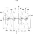
- the radiator for fuel cell 63 is configured by the connection of a plurality of (e.g., 4) cooling units 63A, 63B, 63C, 63D.
- a cooling fan 63E is disposed between the cooling units 63A and 63B, and a cooling fan 63F is disposed between the cooling units 63C and 63D.
- a rotational axis A-A of the cooling fans 63E, 63F inclines upward by an angle ⁇ with respect to a straight line B-B in the horizontal direction.
- the radiator for motor and inverter 64 is configured by the connection of a plurality of (e.g., 2) cooling units 64A, 64B.
- a cooling fan 64C is disposed between the cooling units 64A and 64B.
- the oil cooler 65 is configured by the connection of a plurality of (e.g., 2) cooling units 65A, 65B.
- a cooling fan 65C is disposed between the cooling units 65A and 65B.
- a rotational axis of the cooling fans 64C, 65C inclines upward by an angle ⁇ with respect to the horizontal direction, similarly to the cooling fans 63E, 63F of the radiator for fuel cell 63.
- the upper revolving structure 61 is configured as described above, and its basic operational effect is not particularly different from that in the first embodiment.
- the cooling fans 63E, 63F, 64C, 65C constituting the heat exchanger 62 are disposed upward with respect to the upper revolving structure 61 in the horizontal direction. This configuration can inhibit discharge of the cooling air heated by passing through the heat exchanger 62 to an operator present rearward of the counterweight 7.
- the hydrogen gas stagnant around the hydrogen tank 20 can be discharged upward from the exhaust port 7A of the counterweight 7 in order to discharge the hydrogen gas outward of the upper revolving structure 61, using the cooling air.
- the radiator for fuel cell 63 of the heat exchanger 62 is configured by the connection of a plurality of cooling units 63A, 63B, 63C, 63D.
- the radiator for motor and inverter 64 is configured by the connection of a plurality of cooling units 64A, 64B
- the oil cooler 65 is configured by the connection of a plurality of cooling units 65A, 65B.
- the controller 36 detects the hydrogen gas and the hydrogen gas is discharged outward of the upper revolving structure 3 (the exterior cover 10) when hydrogen gas leakage occurs in the exterior cover 10 and the gas gets stagnant around the hydrogen tank 20 during the filling of hydrogen gas into the hydrogen tank 20 is illustrated.
- the present invention is not limited to that, and as in a first modification shown in Fig. 11 , for example, with the pressure in the hydrogen tank 20 or the pressure in the hydrogen gas line 22 (pressure circuit) decreased, the construction machine may be configured to allow the controller 36 to determine that any hydrogen gas can be present around the hydrogen tank 20 and the air in the exterior cover 10 to be discharge outward.
- Fig. 11 shows control processing performed by the controller 36.
- the controller 36 reads out the pressure in the hydrogen tank 20 or the pressure in the hydrogen gas line 22 to determine whether the pressure is abnormally decreased/lowered or not in step S12.
- step S12 if the controller 36 determines "YES", and in step S13, the pressure in the hydrogen tank 20 or the pressure in the hydrogen gas line 22 is found to be abnormally decreased/lowered, and the process will proceed to step S14.
- step S14 the controller 36 sets rotating directions of the cooling fans 25C, 25D, 26A, 27A such that the operator's seat 9 is on the upstream side of the hydrogen tank 20 with respect to a flow direction of the cooling air, and in step S15, the controller 36 increases the rotational speeds of the cooling fan 25C and the like. Thereafter, in step S16, the controller 36 reads out the pressure in the hydrogen tank 20 or the hydrogen gas line 22 to determine whether the pressure is abnormal or not in step S17.
- step S17 if the controller 36 determines "YES”, the process will return to step S14 to continue the control thereafter, and if the controller determines "NO” in step S17, the cooling fans 25C, 25D, 26A, 27A will be normally operated in step S18 and the control processing will be completed.
- the construction machine may be configured to discharge the air in the exterior cover 10 outward when any hydrogen gas can be present around the hydrogen tank 20.
- whether any hydrogen gas can be present around the hydrogen tank 20 or not may be determined, based upon whether the remaining amount of the hydrogen gas in the hydrogen tank 20 is abnormally decreased/lowered or not. That is, the construction machine may be configured to read out the remaining amount of the hydrogen gas in the hydrogen tank 20 in steps S11 and S16 in Fig. 11 and determine whether the remaining amount of the hydrogen gas is abnormally decreased/lowered or not in steps S12 and S17.
- the radiator for fuel cell 25, the radiator for motor and inverter 26 and the oil cooler 27, each constituting the heat exchanger 24, are disposed from the left side to the right side of the revolving frame 5 is illustrated.
- the present invention is not limited to that, and the radiator for fuel cell 25, the radiator for motor and inverter 26 and the oil cooler 27 are disposed in no particular order with respect to the revolving frame 5 in the right-and-left direction.
- the radiator for fuel cell 25, the radiator for motor and inverter 26 and the oil cooler 27 are disposed in no particular order with respect to the revolving frame 5 in the front-rear direction.
Landscapes
- Engineering & Computer Science (AREA)
- Mining & Mineral Resources (AREA)
- Structural Engineering (AREA)
- General Engineering & Computer Science (AREA)
- Civil Engineering (AREA)
- Chemical & Material Sciences (AREA)
- Manufacturing & Machinery (AREA)
- Electrochemistry (AREA)
- General Chemical & Material Sciences (AREA)
- Chemical Kinetics & Catalysis (AREA)
- Life Sciences & Earth Sciences (AREA)
- Sustainable Energy (AREA)
- Sustainable Development (AREA)
- General Physics & Mathematics (AREA)
- Physics & Mathematics (AREA)
- Automation & Control Theory (AREA)
- Mechanical Engineering (AREA)
- Fuel Cell (AREA)
- Cooling, Air Intake And Gas Exhaust, And Fuel Tank Arrangements In Propulsion Units (AREA)
- Arrangement Or Mounting Of Propulsion Units For Vehicles (AREA)
Abstract
Description
- The present disclosure relates to a construction machine such as a hydraulic excavator including a fuel cell system.
- In recent years, environment-friendly fuel cell systems have been employed in several types of construction machines, such as hydraulic excavators. A fuel cell system is configured to include a fuel cell generating power supplied to an electric motor serving as a power source of a construction machine and a hydrogen tank storing hydrogen supplied to the fuel cell (see Patent Document 1).
- With a decreased amount of hydrogen gas in a hydrogen tank of a construction machine during its operation, a hydrogen gas needs to be filled into the hydrogen tank, using a vehicle with hydrogen supply equipment (mobile hydrogen supply equipment), for example. In this case, the vehicle with the hydrogen supply equipment is moved to be close to the construction machine and a new hydrogen gas is filled into the hydrogen tank, with a filling nozzle of the hydrogen supply equipment connected to the hydrogen tank. In this configuration, hydrogen gas can be stably supplied to a fuel cell of a construction machine that is operated at a working site.
- Patent Document 1:
Japanese Patent Laid-Open No. 2022-180565 A - However, in a case where hydrogen gas is filled from hydrogen supply equipment and supplied to a hydrogen tank included in a construction machine, for example, leakage of hydrogen gas can occur due to abnormal operations in the hydrogen supply equipment or defective filling work of hydrogen, thereby allowing the hydrogen gas to be stagnant around the hydrogen tank. The hydrogen gas stagnant around the hydrogen tank is preferably discharged so as to be swiftly swept away from an operator's seat.
- It is an object of the present invention to provide a construction machine capable of discharging hydrogen gas that is present around a hydrogen tank so as to be swiftly swept away from an operator's seat.
- A construction machine according to the present invention has a self-propelled vehicle body, wherein the vehicle body includes: an operator' s seat; a fuel cell generating power supplied to an electric motor; a hydrogen tank storing hydrogen supplied to the fuel cell; a heat exchanger cooling the fuel cell; and a cooling fan supplying a cooling air to the heat exchanger, characterized in that the operator's seat is disposed on the upstream side of the hydrogen tank with respect to a flow direction of the cooling air generated by the cooling fan.
- According to the present invention, the hydrogen gas that is present around the hydrogen tank can be discharged so as to be swiftly swept away from the operator's seat, using the cooling air flowing from the operator's seat to the hydrogen tank.
-
-
Fig. 1 is a left side view showing a hydraulic excavator according to a first embodiment of the present invention. -
Fig. 2 is a plan view conceptually showing the arrangement of an operator's seat, a fuel cell, a hydrogen tank, a heat exchanger and the like from above. -
Fig. 3 is a left side view conceptually showing the arrangement of the operator's seat, the fuel cell, the hydrogen tank, the heat exchanger and the like from the left side. -
FIG. 4 is a rear view conceptually showing the arrangement of the heat exchanger from the rear. -
Fig. 5 is a block diagram showing the connection of the hydrogen tank, the fuel cell, an electric motor, a controller, the heat exchanger and the like. -
Fig. 6 is a flow chart showing control processing for discharging the hydrogen gas present around the hydrogen tank. -
Fig. 7 is a plan view conceptually showing the arrangement of an operator's seat, a fuel cell, a hydrogen tank, a heat exchanger and the like from above according to a second embodiment. -
Fig. 8 is a left side view conceptually showing the arrangement of a heat exchanger and the like from the left side according to a third embodiment. -
Fig. 9 is a left side view conceptually showing the arrangement of a heat exchanger and the like from the left side according to a fourth embodiment. -
Fig. 10 is a rear view conceptually showing the arrangement of the heat exchanger and the like from the rear according to the fourth embodiment. -
Fig. 11 is a flow chart showing a modification of control processing for discharging hydrogen gas. - A construction machine according to an embodiment of the present invention, by taking the case of a hydraulic excavator, will be explained in detail with reference to
Figs. 1 to 10 . In the embodiment, the running direction of a hydraulic excavator is defined as front-and-rear direction, and the direction perpendicular to the running direction of the hydraulic excavator is defined as right-and-left direction. -
Figs. 1 to 6 illustrates a construction machine according to a first embodiment of the present invention. Ahydraulic excavator 1, as a typical construction machine, includes a self-propelled crawler typelower traveling structure 2 and an upper revolvingstructure 3 mounted rotatably on thelower traveling structure 2. A vehicle body of thehydraulic excavator 1 is configured by thelower traveling structure 2 and the upper revolvingstructure 3. Thehydraulic excavator 1 includes anelectric motor 14 as a power source, afuel cell 11 generating power supplied to theelectric motor 14, and ahydrogen tank 20 storing hydrogen supplied to thefuel cell 11. - The upper revolving
structure 3 is mounted rotatably on thelower traveling structure 2 with a revolvingdevice 4 in between. The upper revolvingstructure 3 has a revolvingframe 5 that constitutes a base. The revolvingframe 5 is configured to include acenter frame 5A located at a center portion in the right-and-left direction, aleft side frame 5B and aright side frame 5C disposed on the left and right sides across thecenter frame 5A. Aworking mechanism 6 excavating earth and sand, etc. is mounted on the front end side of the revolvingframe 5. Acounterweight 7 taking a weight balance with theworking device 6 is provided on the rear end side of the revolvingframe 5. Anexhaust port 7A is formed on a rear surface of thecounterweight 7. - A
cab 8 forming an operator's room is provided on the front left side of the revolvingframe 5. An operator'sseat 9 for an on-board operator to be seated, a traveling lever device, an operating lever device or the like operated by the operator (each not shown) are provided in thecab 8. Anexterior cover 10 is provided on the revolvingframe 5 to be located forward of thecounterweight 7. The later-describedfuel cell 11, theelectric motor 14, ahydraulic pump 16, thehydrogen tank 20, aheat exchanger 24 and the like are accommodated within theexterior cover 10. Theexterior cover 10 has aleft surface 10A, aright surface 10B and an upper surface 10C. An air flow opening 10D communicating the inside and the outside of theexterior cover 10 is formed on theleft surface 10A and theright surface 10B. Anupper cover 10E is provided on the upper surface 10C, covering ahydrogen tank 20, aheat exchanger 24 and the like protruding upward from the upper surface 10C. - The
fuel cell 11 is located rearward of thecab 8 and mounted on the revolvingframe 5. Thefuel cell 11 constitutes a fuel cell system together with a PCU (Power Control Unit) and an auxiliary machine such as a supercharger (each not shown), for example. Thefuel cell 11 generates power supplied to theelectric motor 14, using hydrogen supplied from thehydrogen tank 20. A battery (secondary battery) 12 is mounted on the revolvingframe 5 to be adjacent to the left side of thefuel cell 11. Thebattery 12 stores power in excess of the power supplied to theelectric motor 14 of the power generated by thefuel cell 11, for example. As shown inFig. 5 , thefuel cell 11 and thebattery 12 are connected via a high-voltage cable 13. - The
electric motor 14 is adjacent to the right side of thefuel cell 11 and mounted at a central portion of the revolvingframe 5 in the right-and-left direction. Aninverter 15 is connected to theelectric motor 14 via the high-voltage cable 13. Theinverter 15 is connected to thefuel cell 11 via the high-voltage cable 13. Theinverter 15 converts the direct current power supplied from thefuel cell 11 or thebattery 12 into the alternating current power to be supplied to theelectric motor 14 to control the rotation of theelectric motor 14. - The
hydraulic pump 16 is adjacent to the right side of theelectric motor 14 and mounted on the revolvingframe 5. Thehydraulic pump 16 is driven by theelectric motor 14 to pressurize and discharge the hydraulic oil reserved in a hydraulic oil tank (not shown). Acontrol valve 17 is mounted on the right front side of the revolvingframe 5. Thecontrol valve 17 is connected to each type of hydraulic actuator mounted on thehydraulic excavator 1 and thehydraulic pump 16 via hydraulic lines (not shown) to selectively supply the hydraulic oil (pressurized oil) discharged from thehydraulic pump 16 to each of the hydraulic actuators. - A DC/
DC converter 18 is connected to thefuel cell 11 via the high-voltage cable 13 and connected to later-describedcooling fans cable 19. The DC/DC converter 18 converts the direct current power supplied from thefuel cell 11 or thebattery 12 into the voltage corresponding to thecooling fans controller 36. - The plurality of hydrogen tanks (hydrogen storage vessel) 20 is located to be surrounded by the
fuel cell 11, theelectric motor 14 and thecounterweight 7 and disposed on the rear side of the revolvingframe 5. As shown inFigs. 2 and3 , thehydrogen tank 20 is composed of a cylindrical container excellent in pressure resistance and disposed to extend in the right-and-left direction of the revolvingframe 5. Compressed, high-pressure hydrogen gas is stored within thehydrogen tank 20. Arack 21 is fixed on the rear side of the revolvingframe 5, and the plurality ofhydrogen tanks 20 is held to be aligned in the vertical direction by therack 21. Thehydrogen tank 20 and thefuel cell 11 are connected via ahydrogen gas line 22, and ahydrogen valve 23 is provided in the course of thehydrogen gas line 22. Thehydrogen valve 23 opens and closes thehydrogen gas line 22 in response to a control signal from thecontroller 36, and controls the supply of hydrogen gas from thehydrogen tank 20 to thefuel cell 11. - In order to fill hydrogen gas into the
hydrogen tank 20 mounted on thehydraulic excavator 1 during its operation at a working site, a vehicle (not shown) including hydrogen supply equipment, for example, is moved to be close to thehydraulic excavator 1 and a filling nozzle of the hydrogen supply equipment is connected to thehydrogen tank 20. This configuration allows for filling of compressed hydrogen gas into thehydrogen tank 20 to stably supply hydrogen gas to thefuel cell 11 mounted on thehydraulic excavator 1. - The
heat exchanger 24 is located between thecounterweight 7 and thehydrogen tank 20 and mounted rearward of the revolvingframe 5. Theheat exchanger 24 is configured to include a radiator forfuel cell 25, a radiator for motor andinverter 26 and anoil cooler 27. The radiator forfuel cell 25, the radiator for motor andinverter 26 and theoil cooler 27 are disposed to be aligned in the right-and-left direction of the revolvingframe 5 and face outward of the upper revolvingstructure 3 through theexhaust port 7A of thecounterweight 7. In this way, the mounting of theheat exchanger 24 rearward of the revolvingframe 5 allows devices required for regular maintenance such as thebattery 12 or an oil filter (not shown) to be disposed near theleft surface 10A and theright surface 10B of theexterior cover 10. This configuration can improve the maintainability of these devices. - The radiator for
fuel cell 25 is disposed rearward of thefuel cell 11. The radiator forfuel cell 25 is connected to thefuel cell 11 and a cooling water circulation path (not shown) provided in an auxiliary machine (e.g., PCU, supercharger) incorporated in thefuel cell 11 via acooling water passage 28. As shown inFig. 4 , for example, the radiator forfuel cell 25 is configured by the connection of 2cooling units fans fuel cell 25. The coolingfans exterior cover 10 through theair flow opening 10D formed on theleft surface 10A and theright surface 10B of theexterior cover 10. The outdoor air is collected within theexterior cover 10 and then turns into a cooling air F1 represented by a solid arrow moving from the front side (the operator'sseat 9 side) to the rear side (thehydrogen tank 20 side) of the revolvingframe 5. The cooling air F1 is discharged outward of the upper revolving structure 3 (the exterior cover 10) through theexhaust port 7A of thecounterweight 7. At this time, the heat released from the radiator forfuel cell 25 is transferred into the cooling air F1 to cool thefuel cell 11 and the auxiliary machine. In the coolingfans controller 36. - The radiator for motor and
inverter 26 is disposed rearward of theelectric motor 14. The radiator for motor andinverter 26 is connected to a cooling water circulation path (not shown) provided in theelectric motor 14 and theinverter 15 via acooling water passage 29. A coolingfan 26A composed of an electrically driven fan is mounted on the rear side of the radiator for motor andinverter 26. The heat released from the radiator for motor andinverter 26 and transferred into the cooling air F1 generated by the rotation of the coolingfan 26A cools theelectric motor 14 and theinverter 15. - The
oil cooler 27 is disposed rearward of thehydraulic pump 16. Theoil cooler 27 is connected to a hydraulic circuit to which thehydraulic pump 16 and thecontrol valve 17 are connected via ahydraulic passage 30. The coolingfan 27A composed of an electrically driven fan is mounted on the rear side of theoil cooler 27. The heat released from hydraulic oil (return oil) returning from the hydraulic actuator to a hydraulic oil tank (not shown) and transferred into the cooling air F1 generated by the rotation of the coolingfan 27A cools the hydraulic oil. - A
shroud 31 is provided between thehydrogen tank 20 and theheat exchanger 24. Theshroud 31 is formed of a cylindrical body having a width dimension equivalent to thehydrogen tank 20 in the right-and-left direction of the revolvingframe 5. Theshroud 31 forms a passage for the cooling air F1 between thehydrogen tank 20 and theheat exchanger 24 and introduces the cooling air F1 generated by the rotation of the coolingfans fuel cell 25, the radiator for motor andinverter 26, the oil cooler 27). Herein, the coolingfans shroud 31 are disposed on the downstream side of thehydrogen tank 20 with respect to a flow direction of the cooling air F1. This configuration can reduce turbulent flow from the cooling air F1 hitting thehydrogen tank 20, rectify the flow of the cooling air F1 with theshroud 31 and efficiently supply a large amount of cooling air F1 to theheat exchanger 24. - A
hydrogen sensor 32 is located within theexterior cover 10 mounted on the revolvingframe 5 and provided near thehydrogen tank 20. Thehydrogen sensor 32, e.g., in a case where hydrogen gas leakage occurs when hydrogen gas is filled into thehydrogen tank 20, detects the concentration of the hydrogen gas stagnant around thehydrogen tank 20 and outputs a detection signal to thecontroller 36, depending on the concentration of the hydrogen gas. - A
temperature sensor 33 is provided in the coolingwater passage 28 connected to the radiator forfuel cell 25. Thetemperature sensor 33 detects the temperature of the cooling water flowing in and out of the radiator forfuel cell 25 and outputs a detection signal to thecontroller 36, depending on the temperature. Atemperature sensor 34 is provided in the coolingwater passage 29 connected to the radiator for motor andinverter 26. Thetemperature sensor 34 detects the temperature of the cooling water flowing in and out of the radiator for motor andinverter 26 and outputs a detection signal to thecontroller 36, depending on the temperature. Atemperature sensor 35 is provided in thehydraulic passage 30 connected to theoil cooler 27. Thetemperature sensor 35 detects the temperature of the hydraulic oil flowing in and out of theoil cooler 27 and outputs a detection signal to thecontroller 36, depending on the temperature of the hydraulic oil. - The
controller 36 controls the operation of thefuel cell 11, thebattery 12, theinverter 15, the DC/DC converter 18, thehydrogen valve 23, and the coolingfans hydrogen sensor 32, thetemperature sensors controller 36. Thefuel cell 11, thebattery 12, theinverter 15, the DC/DC converter 18, thehydrogen valve 23 and the coolingfans controller 36. - The
start key 37 is disposed in thecab 8 and operated by an operator to start thecontroller 36. Thecontroller 36 starts thebattery 12, theinverter 15, the DC/DC converter 18, thehydrogen valve 23 and thefuel cell 11. Thecontroller 36 supplies control signals to the coolingfans hydrogen sensor 32 and thetemperature sensors - The
hydraulic excavator 1 of this embodiment, which is configured as described above, will be operated by an operator with the start key 37 in thecab 8 to activate thecontroller 36. Then, thecontroller 36 powers theinverter 15, thebattery 12, the DC/DC converter 18 and thehydrogen valve 23. Once the activation of theinverter 15, thebattery 12, the DC/DC converter 18 and thehydrogen valve 23 is completed, thecontroller 36 starts thefuel cell 11 and thereafter a monitor (not shown) disposed in thecab 8 displays the activation completion of thefuel cell 11. - The operator confirms the activation completion of the
fuel cell 11 with the monitor, and operates keys (not shown) disposed in thecab 8. This operation allows for power generation in thefuel cell 11, discharge or charge in thebattery 12 and driving of theelectric motor 14. As theelectric motor 14 drives thehydraulic pump 16, the hydraulic oil (pressurized oil) discharged from thehydraulic pump 16 is supplied to thecontrol valve 17. Thecontrol valve 17 selectively supplies hydraulic oil to each type of hydraulic actuator, depending on the operation of a traveling lever device and an operating lever device (each not shown) provided in thecab 8. This mechanism allows thehydraulic excavator 1 to propel itself at a working site and revolve the upper revolvingstructure 3 to perform excavating work of sand and earth, using theworking mechanism 6. - After the
fuel cell 11 starts power generation, thecontroller 36 controls the rotation of the coolingfans temperature sensors controller 36 determines the rotational speed of the coolingfans temperature sensor 33, determines the rotational speed of the coolingfan 26A, depending on the temperature of cooling water shown by a detection signal outputted from thetemperature sensor 34 to supply control signals to the coolingfans controller 36 determines the rotational speed of the coolingfan 27A, depending on the temperature of hydraulic oil shown by a detection signal outputted from thetemperature sensor 35 to supply a control signal to the coolingfan 27A. - This mechanism allows the cooling
fans exterior cover 10 through theair flow opening 10D formed on theleft surface 10A and theright surface 10B of theexterior cover 10. The outdoor air is collected within theexterior cover 10 and then turns into a cooling air F1 represented by a solid arrow moving from the front side (the operator'sseat 9 side) to the rear side (thehydrogen tank 20 side) of the revolvingframe 5. The cooling air F1 passes through the radiator forfuel cell 25, the radiator for motor andinverter 26 and theoil cooler 27 for cooling, and then will be discharged outward of the upper revolvingstructure 3 from theexhaust port 7A of thecounterweight 7. - This mechanism, during the operation of the
hydraulic excavator 1, individually controls the coolingfans fuel cell 25, the coolingfan 26A supplying a cooling air to the radiator for motor andinverter 26 and the coolingfan 27A supplying a cooling air to theoil cooler 27. Thus, the hydraulic oil discharged from thefuel cell 11, theelectric motor 14, theinverter 15 and thehydraulic pump 16 can be suitably cooled, depending on the respective temperatures. The flow direction of the cooling air F1 can be changed from the rear side to the front side of the revolvingframe 5 by rotating the coolingfans exhaust port 7A of thecounterweight 7 to flow into theexterior cover 10, and passes through the radiator forfuel cell 25, the radiator for motor andinverter 26 and theoil cooler 27, and then will be discharged outward of the upper revolvingstructure 3 through theair flow opening 10D formed on theleft surface 10A and theright surface 10B of theexterior cover 10. - With a smaller amount of hydrogen gas in the
hydrogen tank 20 of thehydraulic excavator 1 during its operation, a hydrogen gas is filled into thehydrogen tank 20 by moving a vehicle with hydrogen supply equipment (mobile hydrogen supply equipment) to be close to thehydraulic excavator 1, for example. In this case, compressed hydrogen gas is filled into thehydrogen tank 20, with a filling nozzle of the hydrogen supply equipment connected to thehydrogen tank 20 accommodated in theexterior cover 10. For example, as filling hydrogen gas into the vessel, in a case where compressed hydrogen gas leakage occurs due to any malfunction of the hydrogen supply equipment, hydrogen gas is fully filled in theexterior cover 10 and the hydrogen gas can be stagnant around thehydrogen tank 20 until another operation of thehydraulic excavator 1 starts. - On the other hand, in this embodiment, the
hydraulic excavator 1 is configured to discharge hydrogen gas outward of the upper revolvingstructure 3, using the cooling air F1 generated by the coolingfans hydraulic excavator 1 in operation detects the presence of hydrogen gas around thehydrogen tank 20. Control processing performed by thecontroller 36 for detection and discharge of hydrogen gas during the operation of thehydraulic excavator 1 will be described with reference toFig. 6 . - The control processing is started with the start key 37 by activating the
controller 36. In step S1, thecontroller 36 reads out a value of hydrogen concentration around the hydrogen tank 20 (in the exterior cover 10), based upon a detection signal outputted from thehydrogen sensor 32. In the subsequent step S2, thecontroller 36 determines whether the value of hydrogen concentration is abnormal or not by comparison with a predetermined normal value. While the controller determines "NO" in step S2, the value judgment is repeated until the controller determines "YES" in step S2, and then in step S3, the value of hydrogen concentration is found to be abnormal. - If the value of hydrogen concentration is found to be abnormal in step S3, any hydrogen gas is considered to be present (stagnant) around the
hydrogen tank 20. Thus, thecontroller 36 supplies control signals to the coolingfans fans seat 9 is on the upstream side of thehydrogen tank 20 with respect to the flow direction of the cooling air. Specifically, the rotating directions of the coolingfans exterior cover 10 to turn into the cooling air F1 and discharged outward of the upper revolvingstructure 3 through theexhaust port 7A of thecounterweight 7. Consequently, the hydrogen gas present around thehydrogen tank 20 can be discharged outward of the upper revolvingstructure 3 together with the cooling air F1. - Herein, the operator's
seat 9 provided in thecab 8 is disposed on the upstream side of thehydrogen tank 20 with respect to the flow direction of the cooling air F1. Accordingly, the hydrogen gas can be fed away from the operator'sseat 9 and discharged outward of the upper revolvingstructure 3 not through the operator'sseat 9. As shown by a dotted arrow inFig. 2 , the cooling air F2 flowing through theexhaust port 7A of thecounterweight 7 into theexterior cover 10 and discharged outward of the upper revolvingstructure 3 through theair flow opening 10D can cool the radiator forfuel cell 25, the radiator for motor andinverter 26 and theoil cooler 27. In this case, in step S4, thecontroller 36 changes the rotating directions of the coolingfans hydrogen tank 20, thecontroller 36 can set the rotating directions of the coolingfans structure 3 without allowing the gas to pass through the operator'sseat 9. - In the subsequent step S5, the
controller 36 supplies control signals to the coolingfans fans hydrogen tank 20 can be discharged outward of the upper revolving structure 3 (the exterior cover 10) so as to be swiftly swept away from the operator'sseat 9. - Next, in step S6, the
controller 36 reads out the value of hydrogen concentration around thehydrogen tank 20, based upon a detection signal from thehydrogen sensor 32, and in the subsequent step S7, the controller determines whether the value of hydrogen concentration is abnormal or not. If the controller determines "YES" in step S7, meaning that the hydrogen gas is present around thehydrogen tank 20, the process will return to step S4 to repeat the same steps. Meanwhile, if the controller determines "NO" in step S7, the value of hydrogen concentration around thehydrogen tank 20 is found to return to a normal value. Therefore, in step S8, thecontroller 36 completes the control processing after switching the operation of the coolingfans fans water passage 28, the temperature of the cooling water flowing in the coolingwater passage 29 and the temperature of the hydraulic oil flowing in thehydraulic passage 30. - In this way, according to this embodiment, e.g., even in a case where an abnormality of the hydrogen supply equipment causes leakage of hydrogen gas around the
hydrogen tank 20 in order to fill a new hydrogen gas into thehydrogen tank 20 from the hydrogen supply equipment, the hydrogen gas can be fed away from the operator'sseat 9 using the cooling air F1 generated by the coolingfans exhaust port 7A of thecounterweight 7, without passing through the operator'sseat 9. Even in a case where the coolingfans hydrogen tank 20 allows thecontroller 36 to change the rotating directions of the coolingfans structure 3 so as to be swiftly swept away from the operator'sseat 9. - Thus, the
hydraulic excavator 1 according to the embodiment has a self-propelled vehicle body (thelower traveling structure 2 and the upper revolving structure 3), the upper revolvingstructure 3 includes the operator'sseat 9, thefuel cell 11 generating power supplied to theelectric motor 14, thehydrogen tank 20 storing hydrogen supplied to thefuel cell 11, theheat exchanger 24 cooling thefuel cell 11, and the coolingfans heat exchanger 24, and the operator'sseat 9 is disposed on the upstream side of thehydrogen tank 20 with respect to the flow direction of the cooling air F1 generated by the coolingfans - According to this configuration, the cooling air F1 flowing from the operator's
seat 9 side to thehydrogen tank 20 side can discharge the hydrogen gas present around thehydrogen tank 20 outward of the upper revolvingstructure 3 so as to be swiftly swept away from the operator'sseat 9. - The construction machine in the embodiment includes the
shroud 31 introducing the cooling air F1 to theheat exchanger 24, and the coolingfans shroud 31 are disposed on the downstream side of thehydrogen tank 20 with respect to the flow direction of the cooling air F1. This configuration can reduce turbulent flow from the cooling air F1 hitting thehydrogen tank 20 and rectify the flow of the cooling air F1 with theshroud 31. Consequently, a large amount of cooling air F1 can be efficiently supplied to theheat exchanger 24 to facilitate the cooling of thefuel cell 11. - In the construction machine in the embodiment, the
heat exchanger 24 is disposed on the downstream side of thehydrogen tank 20 with respect to the flow direction of the cooling air F1. According to this configuration, the cooling air F1 is discharged outward of the upper revolvingstructure 3 without hitting thehydrogen tank 20 after passing through theheat exchanger 24 to be heated. Consequently, the configuration can inhibit high-temperature exposure of thehydrogen tank 20 and prolong the life of thehydrogen tank 20. - In the embodiment, the
counterweight 7 constituting the upper revolvingstructure 3 is provided with theexhaust port 7A located on the downstream of the coolingfans shroud 31 with respect to the flow direction of the cooling air F1 and discharging the cooling air F1 outward of the upper revolvingstructure 3. According to this configuration, the cooling air F1 passing through theheat exchanger 24 is collected by theshroud 31 and can be efficiently discharged outward of the upper revolvingstructure 3 through theexhaust port 7A. - In the embodiment, the operator's
seat 9 is disposed on the front side of the upper revolvingstructure 3 in the front-rear direction, thehydrogen tank 20 is disposed between the operator'sseat 9 and theheat exchanger 24 with respect to the upper revolvingstructure 3 in the front-rear direction, and theexhaust port 7A discharges the cooling air F1 supplied to theheat exchanger 24 through thehydrogen tank 20 rearward of the upper revolvingstructure 3. According to this configuration, even if any hydrogen gas is stagnant around thehydrogen tank 20, the hydrogen gas can be discharged outward of the upper revolvingstructure 3 through theexhaust port 7A so as to be swiftly swept away from the operator'sseat 9, using the cooling air F1 supplied from theheat exchanger 24. - The construction machine in the embodiment includes the
controller 36 controlling the rotating directions of the coolingfans hydrogen sensor 32 detecting hydrogen gas, and thecontroller 36 switches the rotating directions of the coolingfans seat 9 is on the upstream side of thehydrogen tank 20 with respect to the flow direction of the cooling air F1 when thecontroller 36 allows thehydrogen sensor 32 to detect the hydrogen gas around thehydrogen tank 20. According to this configuration, in a case where hydrogen gas is present around thehydrogen tank 20, thecontroller 36 appropriately sets the rotating directions of the cooling fans 25E, 25F. Thus, the flow direction of the cooling air F1 can be changed so as to allow the operator'sseat 9 to be on the upstream side of thehydrogen tank 20. Consequently, the hydrogen gas present around thehydrogen tank 20 can be fed away from the operator'sseat 9 and swiftly discharged outward of the upper revolvingstructure 3. - In the embodiment, the
heat exchanger 24 is configured to include the radiator forfuel cell 25 cooling thefuel cell 11 and the radiator for motor andinverter 26 cooling theelectric motor 14 and theinverter 15 controlling theelectric motor 14, and the coolingfans fuel cell 25 and the radiator for motor andinverter 26, respectively. According to this configuration, the rotations of the coolingfans fan 26A can be individually controlled when the quantity of heat generated by thefuel cell 11 and the quantity of heat generated by theelectric motor 14 and theinverter 15 are different. Consequently, thefuel cell 11, theelectric motor 14 and theinverter 15 can each be cooled in an optimal state. - Subsequently,
Fig. 7 shows a second embodiment of the present invention. The characteristic of this embodiment lies in the configuration where the cooling air supplied to a heat exchanger through a hydrogen tank is discharged lateralward of an upper revolving structure. In a second embodiment, the component elements that are identical to those of the first embodiment will be simply denoted by the same reference numerals to avoid repetitions of similar explanations. - In the figure, an upper revolving
structure 41 is configured to include, similarly to the upper revolvingstructure 3 in the first embodiment, the revolvingframe 5, thecounterweight 7, thecab 8 provided with the operator'sseat 9 and the like, theexterior cover 10, thefuel cell 11, theelectric motor 14, thehydraulic pump 16, thehydrogen tank 20 and theheat exchanger 24. However, in this embodiment, thefuel cell 11, theelectric motor 14, thehydraulic pump 16, thehydrogen tank 20 and theheat exchanger 24 are disposed in a different manner from those in the first embodiment. - The
counterweight 7 in this embodiment is not provided with theexhaust port 7A of thecounterweight 7 shown in the first embodiment. Further, anexhaust port 10F is provided on aright surface 10B of theexterior cover 10 according to this embodiment, in place of theair flow opening 10D according to the first embodiment. Theexhaust port 10F is composed of an opening with a large area formed almost entirely over theright surface 10B. - The
fuel cell 11 is located rearward of thecab 8 and mounted at a central portion of the revolvingframe 5 in the right-and-left direction. Theelectric motor 14 and thehydraulic pump 16 are disposed between thefuel cell 11 and thecounterweight 7 so as to be adjacent to each other in the right-and-left direction. A plurality ofhydrogen tank 20 is mounted on the revolvingframe 5 so as to be adjacent to the right side of thefuel cell 11 and the electric motor 14 (theright side frame 5C side). The plurality ofhydrogen tank 20 is disposed to be aligned in the vertical direction by arack 21 and to extend in the front-rear direction of the revolvingframe 5. - The
heat exchanger 24 is located rightward of thehydrogen tank 20 and mounted near aright side frame 5C of the revolvingframe 5. Theheat exchanger 24 is configured to include a radiator forfuel cell 25, a radiator for motor andinverter 26 and anoil cooler 27. The radiator forfuel cell 25, the radiator for motor andinverter 26 and theoil cooler 27 are disposed to be aligned in the front-rear direction along theright side frame 5C of the revolvingframe 5 and faces outward of the upper revolvingstructure 3 through theexhaust port 10F formed on theright surface 10B of theexterior cover 10. - The radiator for
fuel cell 25 has 2cooling units counterweight 7. Coolingfans cooling units fuel cell 25. The radiator for motor andinverter 26 is disposed adjacent to the front side of the radiator forfuel cell 25, and a coolingfan 26A is provided on the right side of the radiator for motor andinverter 26. Theoil cooler 27 is disposed adjacent to the front side of the radiator for motor andinverter 26, and a coolingfan 27A is provided on the right side of theoil cooler 27. - The cooling
fans exterior cover 10 through theair flow opening 10D formed on theleft surface 10A of theexterior cover 10. The outdoor air turns into a cooling air F3 represented by a solid arrow moving from theleft surface 10A to theright surface 10B of theexterior cover 10 and is discharged outward of the upper revolving structure 3 (the exterior cover 10) through theexhaust port 10F of theright surface 10B. At this time, the heat released from the radiator forfuel cell 25, the radiator for motor andinverter 26 and theoil cooler 27 is transferred into the cooling air F3 to cool thefuel cell 11 and an auxiliary machine, theelectric motor 14 and theinverter 15, and the hydraulic oil. - Meanwhile, the outdoor air flows through the
exhaust port 10F formed on theright surface 10B of theexterior cover 10 into theexterior cover 10 when the coolingfans right surface 10B onto theleft surface 10A of theexterior cover 10 and is discharged outward of the upper revolvingstructure 3 through the air flow opening 10D of theleft surface 10A. Thus, the heat generated from the radiator forfuel cell 25, the radiator for motor andinverter 26 and theoil cooler 27 is released into the cooling air F4. - The upper revolving
structure 41 according to this embodiment is configured as described above, and the cooling air F3 represented by a solid arrow or the cooling air F4 represented by a dotted arrow is generated in theexterior cover 10, depending on rotating directions of the coolingfans fuel cell 25, the radiator for motor andinverter 26 and theoil cooler 27 can be released into the cooling air F3 or the cooling air F4 to cool thefuel cell 11 and the auxiliary machine, theelectric motor 14 and theinverter 15, and hydraulic oil. - Meanwhile, in a case where for example, an abnormality of hydrogen supply equipment causes hydrogen gas leakage around the
hydrogen tank 20 when a new hydrogen gas is filled into thehydrogen tank 20 from the hydrogen supply equipment, acontroller 36 sets the rotating directions of the coolingfans exterior cover 10. That is, the rotating direction of the cooling air F3 (if generated) remains unchanged, and the rotating direction of the cooling air F4 (if generated) is changed into reverse direction. Thus, the hydrogen gas stagnant around thehydrogen tank 20 can be discharged outward of the upper revolvingstructure 41 through theexhaust port 10F of the exterior cover 10 (theright surface 10B), using the cooling air F4. Consequently, the hydrogen gas present around thehydrogen tank 20 can be fed away from the operator'sseat 9 and swiftly discharged outward of the upper revolvingstructure 3. - Subsequently,
Fig. 8 shows a third embodiment of the present invention. The characteristic of this embodiment lies in the configuration of a cooling fan disposed to incline upward. In the third embodiment, the component elements that are identical to those of the foregoing first embodiment will be simply denoted by the same reference numerals to avoid repetitions of similar explanations. - In the figure, an upper revolving
structure 51 is configured to include, similarly to the upper revolvingstructure 3 in the first embodiment, the revolvingframe 5, thecounterweight 7, thecab 8 provided with the operator'sseat 9 and the like, theexterior cover 10, thefuel cell 11, theelectric motor 14, thehydraulic pump 16, thehydrogen tank 20 and theheat exchanger 24. However, in this embodiment, coolingfans heat exchanger 24 are disposed in a different manner from the first embodiment. - The
heat exchanger 24 is configured to include the radiator forfuel cell 25, the radiator for motor andinverter 26 and theoil cooler 27, as in the first embodiment. The radiator forfuel cell 25 has the coolingfans inverter 26 has the coolingfan 26A, and theoil cooler 27 has the coolingfan 27A. Herein, assuming that a rotational axis of the coolingfan 25C is defined as A-A and a straight line extending in the horizontal direction of the upper revolvingstructure 4 is defined as B-B, the rotational axis A-A of the coolingfan 25C inclines upward by an angle θ with respect to the straight line B-B in the horizontal direction. Similarly, a rotational axis of the coolingfan 25D of the radiator forfuel cell 25, the coolingfan 26A of the radiator for motor andinverter 26 and the coolingfan 27A of theoil cooler 27 also inclines upward by an angle θ with respect to the straight line B-B in the horizontal direction. - In this way, in this embodiment, the cooling
fans fuel cell 25, the cooling fan 26Aof the radiator for motor andinverter 26 and the coolingfan 27A of theoil cooler 27 are disposed to incline upward with respect to the upper revolvingstructure 3 in the horizontal direction. Accordingly, the upper revolvingstructure 51 is configured to discharge a cooling air F5 represented by a solid line passing through the radiator forfuel cell 25, the radiator for motor andinverter 26 and theoil cooler 27 upward from the horizontal direction from the upper revolvingstructure 51 through theexhaust port 7A of thecounterweight 7. - The upper revolving
structure 51 according to this embodiment is configured as described above, and its basic operational effect is not particularly different from that in the first embodiment. However, according to this embodiment, the coolingfans heat exchanger 24 are disposed upward with respect to the upper revolvingstructure 51 in the horizontal direction. This configuration can inhibit discharge of the cooling air heated by passing through theheat exchanger 24 to an operator present rearward of thecounterweight 7. In addition, the hydrogen gas stagnant around thehydrogen tank 20 can be discharged upward from theexhaust port 7A of thecounterweight 7 in order to discharge the hydrogen gas outward of the upper revolvingstructure 51, using the cooling air. Thus, no air flow opening for discharging hydrogen gas that is lighter than the air needs to be provided on the upper surface 10C of theexterior cover 10 to achieve no intrusion of rain water into theexterior cover 10 through the air flow opening. - Subsequently,
Figs. 9 and10 show a fourth embodiment of the present invention. The characteristic of this embodiment lies in the configuration of a heat exchanger by the connection of a plurality of cooling units and the arrangement of cooling fans disposed to incline upward. In the fourth embodiment, the component elements that are identical to those of the foregoing first embodiment will be simply denoted by the same reference numerals to avoid repetitions of similar explanations. - In the figure, an upper revolving
structure 61 is configured to include, similarly to the upper revolvingstructure 3 in the first embodiment, the revolvingframe 5, thecounterweight 7, thecab 8 provided with the operator'sseat 9 and the like, theexterior cover 10, thefuel cell 11, theelectric motor 14, thehydraulic pump 16, thehydrogen tank 20 and aheat exchanger 62. However, in this embodiment, theheat exchanger 62 is configured in a different manner from theheat exchanger 24 according to the first embodiment. - The
heat exchanger 62, similarly to theheat exchanger 24 according to the first embodiment, is located between thecounterweight 7 and thehydrogen tank 20 and is mounted rearward of the revolvingframe 5. Theheat exchanger 62 is configured to include a radiator forfuel cell 63, a radiator for motor andinverter 64 and anoil cooler 65. The radiator forfuel cell 63, the radiator for motor andinverter 64 and theoil cooler 65 are disposed to be aligned in the right-and-left direction of the revolvingframe 5 and face outward of the upper revolvingstructure 61 through theexhaust port 7A of thecounterweight 7. - The radiator for
fuel cell 63 is configured by the connection of a plurality of (e.g., 4) coolingunits fan 63E is disposed between the coolingunits fan 63F is disposed between the coolingunits fans - The radiator for motor and
inverter 64 is configured by the connection of a plurality of (e.g., 2) coolingunits fan 64C is disposed between the coolingunits oil cooler 65 is configured by the connection of a plurality of (e.g., 2) coolingunits fan 65C is disposed between the coolingunits fans fans fuel cell 63. - The upper revolving
structure 61 according to this embodiment is configured as described above, and its basic operational effect is not particularly different from that in the first embodiment. However, according to this embodiment, the coolingfans heat exchanger 62 are disposed upward with respect to the upper revolvingstructure 61 in the horizontal direction. This configuration can inhibit discharge of the cooling air heated by passing through theheat exchanger 62 to an operator present rearward of thecounterweight 7. In addition, the hydrogen gas stagnant around thehydrogen tank 20 can be discharged upward from theexhaust port 7A of thecounterweight 7 in order to discharge the hydrogen gas outward of the upper revolvingstructure 61, using the cooling air. - Moreover, according to this embodiment, the radiator for
fuel cell 63 of theheat exchanger 62 is configured by the connection of a plurality ofcooling units inverter 64 is configured by the connection of a plurality ofcooling units oil cooler 65 is configured by the connection of a plurality ofcooling units structure 61 with a limited space for installing devices, the degree of freedom for installing a plurality ofcooling units fuel cell 63. This advantage also applies to the radiator for motor andinverter 64 and theoil cooler 65. - In the embodiment, the case where the
controller 36 detects the hydrogen gas and the hydrogen gas is discharged outward of the upper revolving structure 3 (the exterior cover 10) when hydrogen gas leakage occurs in theexterior cover 10 and the gas gets stagnant around thehydrogen tank 20 during the filling of hydrogen gas into thehydrogen tank 20 is illustrated. However, the present invention is not limited to that, and as in a first modification shown inFig. 11 , for example, with the pressure in thehydrogen tank 20 or the pressure in the hydrogen gas line 22 (pressure circuit) decreased, the construction machine may be configured to allow thecontroller 36 to determine that any hydrogen gas can be present around thehydrogen tank 20 and the air in theexterior cover 10 to be discharge outward. -
Fig. 11 shows control processing performed by thecontroller 36. In step S11, thecontroller 36 reads out the pressure in thehydrogen tank 20 or the pressure in thehydrogen gas line 22 to determine whether the pressure is abnormally decreased/lowered or not in step S12. In step S12, if thecontroller 36 determines "YES", and in step S13, the pressure in thehydrogen tank 20 or the pressure in thehydrogen gas line 22 is found to be abnormally decreased/lowered, and the process will proceed to step S14. - Thus, in step S14, the
controller 36 sets rotating directions of the coolingfans seat 9 is on the upstream side of thehydrogen tank 20 with respect to a flow direction of the cooling air, and in step S15, thecontroller 36 increases the rotational speeds of the coolingfan 25C and the like. Thereafter, in step S16, thecontroller 36 reads out the pressure in thehydrogen tank 20 or thehydrogen gas line 22 to determine whether the pressure is abnormal or not in step S17. - Then, in step S17, if the
controller 36 determines "YES", the process will return to step S14 to continue the control thereafter, and if the controller determines "NO" in step S17, the coolingfans exterior cover 10 outward when any hydrogen gas can be present around thehydrogen tank 20. - In this case, whether any hydrogen gas can be present around the
hydrogen tank 20 or not may be determined, based upon whether the remaining amount of the hydrogen gas in thehydrogen tank 20 is abnormally decreased/lowered or not. That is, the construction machine may be configured to read out the remaining amount of the hydrogen gas in thehydrogen tank 20 in steps S11 and S16 inFig. 11 and determine whether the remaining amount of the hydrogen gas is abnormally decreased/lowered or not in steps S12 and S17. - In the first embodiment, the case where the radiator for
fuel cell 25, the radiator for motor andinverter 26 and theoil cooler 27, each constituting theheat exchanger 24, are disposed from the left side to the right side of the revolvingframe 5 is illustrated. However, the present invention is not limited to that, and the radiator forfuel cell 25, the radiator for motor andinverter 26 and theoil cooler 27 are disposed in no particular order with respect to the revolvingframe 5 in the right-and-left direction. Likewise, in the second embodiment, the radiator forfuel cell 25, the radiator for motor andinverter 26 and theoil cooler 27 are disposed in no particular order with respect to the revolvingframe 5 in the front-rear direction. -
- 2: Lower traveling structure (Vehicle body)
- 3, 41, 51, 61: Upper revolving structure (Vehicle body)
- 7: Counterweight
- 7A: Exhaust port
- 9: Operator's seat
- 10: Exterior cover
- 10F: Exhaust port
- 11: Fuel cell
- 14: Electric motor
- 20: Hydrogen tank
- 24, 62: Heat exchanger
- 25, 63: Radiator for fuel cell
- 25C, 25D, 26A, 27A, 63E, 63F, 64C, 65C: Cooling fan
- 26, 64: Radiator for motor and inverter
- 27, 65: Oil cooler
- 31: Shroud
- 32: Hydrogen sensor
- 36: Controller
Claims (9)
- A construction machine having a self-propelled vehicle body, whereinthe vehicle body comprises: an operator's seat; a fuel cell generating power supplied to an electric motor; a hydrogen tank storing hydrogen supplied to the fuel cell; a heat exchanger cooling the fuel cell; and a cooling fan supplying a cooling air to the heat exchanger, characterized in thatthe operator's seat is disposed on the upstream side of the hydrogen tank with respect to a flow direction of the cooling air generated by the cooling fan.
- The construction machine according to claim 1, comprising a shroud introducing the cooling air to the heat exchanger, wherein
the cooling fan and the shroud are disposed on the downstream side of the hydrogen tank with respect to the flow direction of the cooling air. - The construction machine according to claim 1, wherein
the heat exchanger is disposed on the downstream side of the hydrogen tank with respect to the flow direction of the cooling air. - The construction machine according to claim 2, comprising an exhaust port located on the downstream of the cooling fan and the shroud with respect to the flow direction of the cooling air and discharging the cooling air outward of the vehicle body.
- The construction machine according to claim 4, whereinthe operator's seat is disposed on the front side of the vehicle body in the front-rear direction,the hydrogen tank is disposed between the operator's seat and the heat exchanger with respect to the vehicle body in the front-rear direction, andthe exhaust port discharges the cooling air supplied to the heat exchanger through the hydrogen tank rearward of the vehicle body.
- The construction machine according to claim 4, whereinthe operator's seat is disposed on one side of the vehicle body in the right-and-left direction,the hydrogen tank is disposed between the operator's seat and the heat exchanger with respect to the vehicle body in the right-and-left direction, andthe exhaust port discharges the cooling air supplied to the heat exchanger through the hydrogen tank lateralward.
- The construction machine according to claim 1, comprising: a controller controlling a rotating direction of the cooling fan; anda hydrogen sensor detecting hydrogen gas, whereinthe controller switches the rotating direction of the cooling fan such that the operator's seat is on the upstream side of the hydrogen tank with respect to the flow direction of the cooling air when the controller allows the hydrogen sensor to detect hydrogen gas around the hydrogen tank.
- The construction machine according to claim 1, wherein
the cooling fan is disposed to incline upward. - The construction machine according to claim 1, whereinthe heat exchanger is configured to include a radiator for fuel cell cooling the fuel cell and a radiator for motor and inverter cooling the electric motor and an inverter controlling the electric motor, whereinthe cooling fan is individually provided for the radiator for fuel cell and the radiator for motor and inverter.
Applications Claiming Priority (1)
| Application Number | Priority Date | Filing Date | Title |
|---|---|---|---|
| PCT/JP2023/013241 WO2024201914A1 (en) | 2023-03-30 | 2023-03-30 | Construction machine |
Publications (2)
| Publication Number | Publication Date |
|---|---|
| EP4553236A1 true EP4553236A1 (en) | 2025-05-14 |
| EP4553236A4 EP4553236A4 (en) | 2026-04-29 |
Family
ID=92904385
Family Applications (1)
| Application Number | Title | Priority Date | Filing Date |
|---|---|---|---|
| EP23930552.7A Pending EP4553236A4 (en) | 2023-03-30 | 2023-03-30 | CONSTRUCTION MACHINE |
Country Status (6)
| Country | Link |
|---|---|
| US (1) | US20260085490A1 (en) |
| EP (1) | EP4553236A4 (en) |
| JP (1) | JPWO2024201914A1 (en) |
| KR (1) | KR20250042789A (en) |
| CN (1) | CN119452140A (en) |
| WO (1) | WO2024201914A1 (en) |
Family Cites Families (13)
| Publication number | Priority date | Publication date | Assignee | Title |
|---|---|---|---|---|
| JPH04368227A (en) * | 1991-06-14 | 1992-12-21 | Mazda Motor Corp | Automobile with hydrogen engine |
| JPH07259129A (en) * | 1994-03-15 | 1995-10-09 | Yutani Heavy Ind Ltd | Removable noise reduction device for construction and work machines |
| JPH11269918A (en) * | 1998-03-20 | 1999-10-05 | Shin Caterpillar Mitsubishi Ltd | Cooling equipment for construction machinery |
| JPH11269919A (en) * | 1998-03-24 | 1999-10-05 | Shin Caterpillar Mitsubishi Ltd | Cooling equipment for construction machinery |
| JP2008296615A (en) * | 2007-05-29 | 2008-12-11 | Hitachi Constr Mach Co Ltd | Construction machine |
| JP5097020B2 (en) * | 2008-06-06 | 2012-12-12 | 本田技研工業株式会社 | Mobile body equipped with fuel cell and control method thereof |
| JP6309187B2 (en) * | 2012-09-25 | 2018-04-11 | 株式会社豊田自動織機 | Industrial vehicle |
| JP7025307B2 (en) * | 2018-08-31 | 2022-02-24 | 日立建機株式会社 | Construction machinery |
| NO20200361A1 (en) * | 2020-03-26 | 2021-09-27 | Elmaco As | DEVICE FOR CONSTRUCTION MACHINE WITH ENERGY SUPPLY FROM HYDROGEN FUEL CELL AND TRANSFER WITH HYDRAULICS AND VOLUME NEUTRAL HYDRAULIC CYLINDERS |
| US11821166B2 (en) * | 2020-07-22 | 2023-11-21 | Caterpillar Underground Mining Pty. Ltd. | Internal support structure for underground battery machines |
| EP4265855A4 (en) * | 2020-12-17 | 2024-12-11 | Kubota Corporation | WORKING MACHINE |
| US20230417016A1 (en) | 2020-12-21 | 2023-12-28 | Jdc Corporation | Construction Machine |
| JP7423560B2 (en) * | 2021-02-03 | 2024-01-29 | ヤンマーホールディングス株式会社 | Work vehicle cooling system and work vehicle |
-
2023
- 2023-03-30 CN CN202380050018.XA patent/CN119452140A/en active Pending
- 2023-03-30 EP EP23930552.7A patent/EP4553236A4/en active Pending
- 2023-03-30 KR KR1020257005714A patent/KR20250042789A/en active Pending
- 2023-03-30 US US19/106,687 patent/US20260085490A1/en active Pending
- 2023-03-30 JP JP2025509510A patent/JPWO2024201914A1/ja active Pending
- 2023-03-30 WO PCT/JP2023/013241 patent/WO2024201914A1/en not_active Ceased
Also Published As
| Publication number | Publication date |
|---|---|
| JPWO2024201914A1 (en) | 2024-10-03 |
| US20260085490A1 (en) | 2026-03-26 |
| WO2024201914A1 (en) | 2024-10-03 |
| EP4553236A4 (en) | 2026-04-29 |
| CN119452140A (en) | 2025-02-14 |
| KR20250042789A (en) | 2025-03-27 |
Similar Documents
| Publication | Publication Date | Title |
|---|---|---|
| CN108138469B (en) | Hybrid construction machine | |
| EP4008840B1 (en) | Excavator | |
| US6678972B2 (en) | Hybrid construction equipment | |
| US10000908B2 (en) | Hybrid-type working machine | |
| US10066358B2 (en) | Hybrid-type working machine | |
| KR20170024611A (en) | Hybrid construction machine | |
| JP7581380B2 (en) | Electric work machine | |
| JP6112667B2 (en) | Hybrid work machine | |
| US20240240433A1 (en) | Electric excavator | |
| JP6291427B2 (en) | Hybrid work machine | |
| EP1199410B1 (en) | Construction machine | |
| JP5155112B2 (en) | Electric hydraulic work machine | |
| JP2004169466A (en) | Equipment arrangement structure of construction machinery | |
| KR20230118814A (en) | construction machinery | |
| KR20170023703A (en) | Hybrid work vehicle | |
| US20260085490A1 (en) | Construction Machine | |
| JP2001012418A (en) | Hybrid work machine | |
| JP7826598B2 (en) | electric shovel | |
| JP7817498B2 (en) | Construction machinery | |
| JP5956386B2 (en) | Hybrid work machine | |
| JP2020153115A (en) | Excavator | |
| KR20160087566A (en) | Construction machinery | |
| EP4421248B1 (en) | Working vehicle | |
| CN121311649A (en) | construction machinery | |
| WO2025234211A1 (en) | Work machine and method for controlling work machine |
Legal Events
| Date | Code | Title | Description |
|---|---|---|---|
| STAA | Information on the status of an ep patent application or granted ep patent |
Free format text: STATUS: THE INTERNATIONAL PUBLICATION HAS BEEN MADE |
|
| PUAI | Public reference made under article 153(3) epc to a published international application that has entered the european phase |
Free format text: ORIGINAL CODE: 0009012 |
|
| STAA | Information on the status of an ep patent application or granted ep patent |
Free format text: STATUS: REQUEST FOR EXAMINATION WAS MADE |
|
| 17P | Request for examination filed |
Effective date: 20250205 |
|
| AK | Designated contracting states |
Kind code of ref document: A1 Designated state(s): AL AT BE BG CH CY CZ DE DK EE ES FI FR GB GR HR HU IE IS IT LI LT LU LV MC ME MK MT NL NO PL PT RO RS SE SI SK SM TR |
|
| A4 | Supplementary search report drawn up and despatched |
Effective date: 20260330 |
|
| RIC1 | Information provided on ipc code assigned before grant |
Ipc: E02F 9/24 20060101AFI20260324BHEP Ipc: E02F 3/32 20060101ALI20260324BHEP Ipc: H01M 8/0444 20160101ALI20260324BHEP Ipc: E02F 9/08 20060101ALI20260324BHEP Ipc: E02F 9/20 20060101ALI20260324BHEP Ipc: H01M 8/04007 20160101ALI20260324BHEP Ipc: H01M 8/04082 20160101ALI20260324BHEP |
|
| DAV | Request for validation of the european patent (deleted) | ||
| DAX | Request for extension of the european patent (deleted) |