JP7581380B2 - Electric work machine - Google Patents
Electric work machine Download PDFInfo
- Publication number
- JP7581380B2 JP7581380B2 JP2022569825A JP2022569825A JP7581380B2 JP 7581380 B2 JP7581380 B2 JP 7581380B2 JP 2022569825 A JP2022569825 A JP 2022569825A JP 2022569825 A JP2022569825 A JP 2022569825A JP 7581380 B2 JP7581380 B2 JP 7581380B2
- Authority
- JP
- Japan
- Prior art keywords
- battery pack
- battery
- charging
- discharge
- control device
- Prior art date
- Legal status (The legal status is an assumption and is not a legal conclusion. Google has not performed a legal analysis and makes no representation as to the accuracy of the status listed.)
- Active
Links
Images


Classifications
-
- E—FIXED CONSTRUCTIONS
- E02—HYDRAULIC ENGINEERING; FOUNDATIONS; SOIL SHIFTING
- E02F—DREDGING; SOIL-SHIFTING
- E02F9/00—Component parts of dredgers or soil-shifting machines, not restricted to one of the kinds covered by groups E02F3/00 - E02F7/00
- E02F9/20—Drives; Control devices
- E02F9/2058—Electric or electro-mechanical or mechanical control devices of vehicle sub-units
- E02F9/2062—Control of propulsion units
- E02F9/207—Control of propulsion units of the type electric propulsion units, e.g. electric motors or generators
-
- B—PERFORMING OPERATIONS; TRANSPORTING
- B60—VEHICLES IN GENERAL
- B60L—PROPULSION OF ELECTRICALLY-PROPELLED VEHICLES; SUPPLYING ELECTRIC POWER FOR AUXILIARY EQUIPMENT OF ELECTRICALLY-PROPELLED VEHICLES; ELECTRODYNAMIC BRAKE SYSTEMS FOR VEHICLES IN GENERAL; MAGNETIC SUSPENSION OR LEVITATION FOR VEHICLES; MONITORING OPERATING VARIABLES OF ELECTRICALLY-PROPELLED VEHICLES; ELECTRIC SAFETY DEVICES FOR ELECTRICALLY-PROPELLED VEHICLES
- B60L1/00—Supplying electric power to auxiliary equipment of vehicles
- B60L1/003—Supplying electric power to auxiliary equipment of vehicles to auxiliary motors, e.g. for pumps, compressors
-
- B—PERFORMING OPERATIONS; TRANSPORTING
- B60—VEHICLES IN GENERAL
- B60L—PROPULSION OF ELECTRICALLY-PROPELLED VEHICLES; SUPPLYING ELECTRIC POWER FOR AUXILIARY EQUIPMENT OF ELECTRICALLY-PROPELLED VEHICLES; ELECTRODYNAMIC BRAKE SYSTEMS FOR VEHICLES IN GENERAL; MAGNETIC SUSPENSION OR LEVITATION FOR VEHICLES; MONITORING OPERATING VARIABLES OF ELECTRICALLY-PROPELLED VEHICLES; ELECTRIC SAFETY DEVICES FOR ELECTRICALLY-PROPELLED VEHICLES
- B60L1/00—Supplying electric power to auxiliary equipment of vehicles
- B60L1/02—Supplying electric power to auxiliary equipment of vehicles to electric heating circuits
- B60L1/04—Supplying electric power to auxiliary equipment of vehicles to electric heating circuits fed by the power supply line
- B60L1/06—Supplying electric power to auxiliary equipment of vehicles to electric heating circuits fed by the power supply line using only one supply
- B60L1/08—Methods and devices for control or regulation
-
- B—PERFORMING OPERATIONS; TRANSPORTING
- B60—VEHICLES IN GENERAL
- B60L—PROPULSION OF ELECTRICALLY-PROPELLED VEHICLES; SUPPLYING ELECTRIC POWER FOR AUXILIARY EQUIPMENT OF ELECTRICALLY-PROPELLED VEHICLES; ELECTRODYNAMIC BRAKE SYSTEMS FOR VEHICLES IN GENERAL; MAGNETIC SUSPENSION OR LEVITATION FOR VEHICLES; MONITORING OPERATING VARIABLES OF ELECTRICALLY-PROPELLED VEHICLES; ELECTRIC SAFETY DEVICES FOR ELECTRICALLY-PROPELLED VEHICLES
- B60L3/00—Electric devices on electrically-propelled vehicles for safety purposes; Monitoring operating variables, e.g. speed, deceleration or energy consumption
- B60L3/0023—Detecting, eliminating, remedying or compensating for drive train abnormalities, e.g. failures within the drive train
- B60L3/0046—Detecting, eliminating, remedying or compensating for drive train abnormalities, e.g. failures within the drive train relating to electric energy storage systems, e.g. batteries or capacitors
-
- B—PERFORMING OPERATIONS; TRANSPORTING
- B60—VEHICLES IN GENERAL
- B60L—PROPULSION OF ELECTRICALLY-PROPELLED VEHICLES; SUPPLYING ELECTRIC POWER FOR AUXILIARY EQUIPMENT OF ELECTRICALLY-PROPELLED VEHICLES; ELECTRODYNAMIC BRAKE SYSTEMS FOR VEHICLES IN GENERAL; MAGNETIC SUSPENSION OR LEVITATION FOR VEHICLES; MONITORING OPERATING VARIABLES OF ELECTRICALLY-PROPELLED VEHICLES; ELECTRIC SAFETY DEVICES FOR ELECTRICALLY-PROPELLED VEHICLES
- B60L58/00—Methods or circuit arrangements for monitoring or controlling batteries or fuel cells, specially adapted for electric vehicles
- B60L58/10—Methods or circuit arrangements for monitoring or controlling batteries or fuel cells, specially adapted for electric vehicles for monitoring or controlling batteries
- B60L58/12—Methods or circuit arrangements for monitoring or controlling batteries or fuel cells, specially adapted for electric vehicles for monitoring or controlling batteries responding to state of charge [SoC]
- B60L58/13—Maintaining the SoC within a determined range
-
- B—PERFORMING OPERATIONS; TRANSPORTING
- B60—VEHICLES IN GENERAL
- B60L—PROPULSION OF ELECTRICALLY-PROPELLED VEHICLES; SUPPLYING ELECTRIC POWER FOR AUXILIARY EQUIPMENT OF ELECTRICALLY-PROPELLED VEHICLES; ELECTRODYNAMIC BRAKE SYSTEMS FOR VEHICLES IN GENERAL; MAGNETIC SUSPENSION OR LEVITATION FOR VEHICLES; MONITORING OPERATING VARIABLES OF ELECTRICALLY-PROPELLED VEHICLES; ELECTRIC SAFETY DEVICES FOR ELECTRICALLY-PROPELLED VEHICLES
- B60L58/00—Methods or circuit arrangements for monitoring or controlling batteries or fuel cells, specially adapted for electric vehicles
- B60L58/10—Methods or circuit arrangements for monitoring or controlling batteries or fuel cells, specially adapted for electric vehicles for monitoring or controlling batteries
- B60L58/18—Methods or circuit arrangements for monitoring or controlling batteries or fuel cells, specially adapted for electric vehicles for monitoring or controlling batteries of two or more battery modules
- B60L58/22—Balancing the charge of battery modules
-
- E—FIXED CONSTRUCTIONS
- E02—HYDRAULIC ENGINEERING; FOUNDATIONS; SOIL SHIFTING
- E02F—DREDGING; SOIL-SHIFTING
- E02F9/00—Component parts of dredgers or soil-shifting machines, not restricted to one of the kinds covered by groups E02F3/00 - E02F7/00
- E02F9/20—Drives; Control devices
- E02F9/2058—Electric or electro-mechanical or mechanical control devices of vehicle sub-units
- E02F9/2091—Control of energy storage means for electrical energy, e.g. battery or capacitors
-
- E—FIXED CONSTRUCTIONS
- E02—HYDRAULIC ENGINEERING; FOUNDATIONS; SOIL SHIFTING
- E02F—DREDGING; SOIL-SHIFTING
- E02F9/00—Component parts of dredgers or soil-shifting machines, not restricted to one of the kinds covered by groups E02F3/00 - E02F7/00
- E02F9/20—Drives; Control devices
- E02F9/22—Hydraulic or pneumatic drives
- E02F9/2278—Hydraulic circuits
- E02F9/2285—Pilot-operated systems
-
- E—FIXED CONSTRUCTIONS
- E02—HYDRAULIC ENGINEERING; FOUNDATIONS; SOIL SHIFTING
- E02F—DREDGING; SOIL-SHIFTING
- E02F9/00—Component parts of dredgers or soil-shifting machines, not restricted to one of the kinds covered by groups E02F3/00 - E02F7/00
- E02F9/26—Indicating devices
- E02F9/267—Diagnosing or detecting failure of vehicles
-
- H—ELECTRICITY
- H02—GENERATION; CONVERSION OR DISTRIBUTION OF ELECTRIC POWER
- H02J—ELECTRIC POWER NETWORKS; CIRCUIT ARRANGEMENTS OR SYSTEMS FOR SUPPLYING OR DISTRIBUTING ELECTRIC POWER; SYSTEMS FOR STORING ELECTRIC ENERGY
- H02J7/00—Circuit arrangements for charging or discharging batteries or for supplying loads from batteries
- H02J7/14—Circuit arrangements for charging or discharging batteries or for supplying loads from batteries for charging batteries from dynamo-electric generators driven at varying speed, e.g. on vehicle
- H02J7/1423—Circuit arrangements for charging or discharging batteries or for supplying loads from batteries for charging batteries from dynamo-electric generators driven at varying speed, e.g. on vehicle with multiple batteries
-
- H—ELECTRICITY
- H02—GENERATION; CONVERSION OR DISTRIBUTION OF ELECTRIC POWER
- H02J—ELECTRIC POWER NETWORKS; CIRCUIT ARRANGEMENTS OR SYSTEMS FOR SUPPLYING OR DISTRIBUTING ELECTRIC POWER; SYSTEMS FOR STORING ELECTRIC ENERGY
- H02J7/00—Circuit arrangements for charging or discharging batteries or for supplying loads from batteries
- H02J7/14—Circuit arrangements for charging or discharging batteries or for supplying loads from batteries for charging batteries from dynamo-electric generators driven at varying speed, e.g. on vehicle
- H02J7/1438—Circuit arrangements for charging or discharging batteries or for supplying loads from batteries for charging batteries from dynamo-electric generators driven at varying speed, e.g. on vehicle in combination with power supplies for loads other than batteries
-
- H—ELECTRICITY
- H02—GENERATION; CONVERSION OR DISTRIBUTION OF ELECTRIC POWER
- H02J—ELECTRIC POWER NETWORKS; CIRCUIT ARRANGEMENTS OR SYSTEMS FOR SUPPLYING OR DISTRIBUTING ELECTRIC POWER; SYSTEMS FOR STORING ELECTRIC ENERGY
- H02J7/00—Circuit arrangements for charging or discharging batteries or for supplying loads from batteries
- H02J7/14—Circuit arrangements for charging or discharging batteries or for supplying loads from batteries for charging batteries from dynamo-electric generators driven at varying speed, e.g. on vehicle
- H02J7/1446—Circuit arrangements for charging or discharging batteries or for supplying loads from batteries for charging batteries from dynamo-electric generators driven at varying speed, e.g. on vehicle in response to parameters of a vehicle
-
- H—ELECTRICITY
- H02—GENERATION; CONVERSION OR DISTRIBUTION OF ELECTRIC POWER
- H02J—ELECTRIC POWER NETWORKS; CIRCUIT ARRANGEMENTS OR SYSTEMS FOR SUPPLYING OR DISTRIBUTING ELECTRIC POWER; SYSTEMS FOR STORING ELECTRIC ENERGY
- H02J7/00—Circuit arrangements for charging or discharging batteries or for supplying loads from batteries
- H02J7/50—Circuit arrangements for charging or discharging batteries or for supplying loads from batteries acting upon multiple batteries simultaneously or sequentially
- H02J7/52—Circuit arrangements for charging or discharging batteries or for supplying loads from batteries acting upon multiple batteries simultaneously or sequentially for charge balancing, e.g. equalisation of charge between batteries
- H02J7/56—Active balancing, e.g. using capacitor-based, inductor-based or DC-DC converters
-
- H—ELECTRICITY
- H02—GENERATION; CONVERSION OR DISTRIBUTION OF ELECTRIC POWER
- H02J—ELECTRIC POWER NETWORKS; CIRCUIT ARRANGEMENTS OR SYSTEMS FOR SUPPLYING OR DISTRIBUTING ELECTRIC POWER; SYSTEMS FOR STORING ELECTRIC ENERGY
- H02J7/00—Circuit arrangements for charging or discharging batteries or for supplying loads from batteries
- H02J7/80—Circuit arrangements for charging or discharging batteries or for supplying loads from batteries including monitoring or indicating arrangements
- H02J7/82—Control of state of charge [SOC]
-
- H—ELECTRICITY
- H02—GENERATION; CONVERSION OR DISTRIBUTION OF ELECTRIC POWER
- H02J—ELECTRIC POWER NETWORKS; CIRCUIT ARRANGEMENTS OR SYSTEMS FOR SUPPLYING OR DISTRIBUTING ELECTRIC POWER; SYSTEMS FOR STORING ELECTRIC ENERGY
- H02J7/00—Circuit arrangements for charging or discharging batteries or for supplying loads from batteries
- H02J7/855—Circuit arrangements for charging or discharging batteries or for supplying loads from batteries with circuits adapted for supplying loads from the battery
-
- B—PERFORMING OPERATIONS; TRANSPORTING
- B60—VEHICLES IN GENERAL
- B60L—PROPULSION OF ELECTRICALLY-PROPELLED VEHICLES; SUPPLYING ELECTRIC POWER FOR AUXILIARY EQUIPMENT OF ELECTRICALLY-PROPELLED VEHICLES; ELECTRODYNAMIC BRAKE SYSTEMS FOR VEHICLES IN GENERAL; MAGNETIC SUSPENSION OR LEVITATION FOR VEHICLES; MONITORING OPERATING VARIABLES OF ELECTRICALLY-PROPELLED VEHICLES; ELECTRIC SAFETY DEVICES FOR ELECTRICALLY-PROPELLED VEHICLES
- B60L2200/00—Type of vehicles
- B60L2200/40—Working vehicles
-
- E—FIXED CONSTRUCTIONS
- E02—HYDRAULIC ENGINEERING; FOUNDATIONS; SOIL SHIFTING
- E02F—DREDGING; SOIL-SHIFTING
- E02F9/00—Component parts of dredgers or soil-shifting machines, not restricted to one of the kinds covered by groups E02F3/00 - E02F7/00
- E02F9/08—Superstructures; Supports for superstructures
- E02F9/0858—Arrangement of component parts installed on superstructures not otherwise provided for, e.g. electric components, fenders, air-conditioning units
- E02F9/0866—Engine compartment, e.g. heat exchangers, exhaust filters, cooling devices, silencers, mufflers, position of hydraulic pumps in the engine compartment
-
- H—ELECTRICITY
- H02—GENERATION; CONVERSION OR DISTRIBUTION OF ELECTRIC POWER
- H02J—ELECTRIC POWER NETWORKS; CIRCUIT ARRANGEMENTS OR SYSTEMS FOR SUPPLYING OR DISTRIBUTING ELECTRIC POWER; SYSTEMS FOR STORING ELECTRIC ENERGY
- H02J2105/00—Networks for supplying or distributing electric power characterised by their spatial reach or by the load
- H02J2105/30—Networks for supplying or distributing electric power characterised by their spatial reach or by the load the load networks being external to vehicles, i.e. exchanging power with vehicles
- H02J2105/33—Networks for supplying or distributing electric power characterised by their spatial reach or by the load the load networks being external to vehicles, i.e. exchanging power with vehicles exchanging power with road vehicles
- H02J2105/37—Networks for supplying or distributing electric power characterised by their spatial reach or by the load the load networks being external to vehicles, i.e. exchanging power with vehicles exchanging power with road vehicles exchanging power with electric vehicles [EV] or with hybrid electric vehicles [HEV]
-
- Y—GENERAL TAGGING OF NEW TECHNOLOGICAL DEVELOPMENTS; GENERAL TAGGING OF CROSS-SECTIONAL TECHNOLOGIES SPANNING OVER SEVERAL SECTIONS OF THE IPC; TECHNICAL SUBJECTS COVERED BY FORMER USPC CROSS-REFERENCE ART COLLECTIONS [XRACs] AND DIGESTS
- Y02—TECHNOLOGIES OR APPLICATIONS FOR MITIGATION OR ADAPTATION AGAINST CLIMATE CHANGE
- Y02E—REDUCTION OF GREENHOUSE GAS [GHG] EMISSIONS, RELATED TO ENERGY GENERATION, TRANSMISSION OR DISTRIBUTION
- Y02E60/00—Enabling technologies; Technologies with a potential or indirect contribution to GHG emissions mitigation
- Y02E60/10—Energy storage using batteries
Landscapes
- Engineering & Computer Science (AREA)
- Power Engineering (AREA)
- Transportation (AREA)
- Mechanical Engineering (AREA)
- Sustainable Development (AREA)
- Sustainable Energy (AREA)
- Life Sciences & Earth Sciences (AREA)
- Mining & Mineral Resources (AREA)
- Civil Engineering (AREA)
- General Engineering & Computer Science (AREA)
- Structural Engineering (AREA)
- Operation Control Of Excavators (AREA)
- Charge And Discharge Circuits For Batteries Or The Like (AREA)
Description
本発明は、バッテリの電力で動作する電動作業機に関する。 The present invention relates to an electric work machine that runs on battery power.
特許文献1には、バッテリパック(バッテリ系統)を複数搭載し、いずれか1つのバッテリパックを選択して放電又は充電する電動式建設機械が開示されている。Patent document 1 discloses an electric construction machine that is equipped with multiple battery packs (battery systems) and selects one of the battery packs to discharge or charge.
しかしながら、特許文献1の技術では、充電又は放電を行うバッテリパックを手動で選択するか、あるいは、予め決められた順番(第1バッテリ系統、第2バッテリ系統の順)で自動的に切り替えるようになっている。このため、複数のバッテリパックを効率的に利用できない場合がある。However, in the technology of Patent Document 1, the battery pack to be charged or discharged is manually selected, or automatically switched in a predetermined order (first battery system, then second battery system). For this reason, there are cases where multiple battery packs cannot be used efficiently.
本発明は、このような従来技術の問題点を解決すべくなされたものであって、複数のバッテリパックを効率良く使用することを目的とする。The present invention has been made to solve these problems with the prior art and aims to make efficient use of multiple battery packs.
本発明の一態様に係る電動作業機は、複数のバッテリパックと、前記バッテリパックから放電される電力により駆動する作業装置と、前記各バッテリパックの状態を監視するバッテリ監視装置と、前記バッテリパックの充電及び放電を制御する制御装置と、を備えた電動作業機であって、前記バッテリ監視装置は、前記各バッテリパックの残容量を監視し、前記制御装置は、前記作業装置を駆動する放電モードでは、前記バッテリ監視装置による前記各バッテリパックの監視結果に基づいて、前記複数のバッテリパックのうち前記残容量が最も多いバッテリパックを前記作業装置に電力を供給するために放電する放電用バッテリパックとして決定して、当該放電用バッテリパックから放電し、前記放電中に、前記放電用バッテリパックとして使用している前記バッテリパックの前記残容量が、当該電動作業機を安全な姿勢に移行させるのに要する電力量以上或いは充電準備が整う場所への当該電動作業機の移動に要する電力量以上に設定された第1閾値以下に低下したときに、他の前記バッテリパックの前記残容量を確認して、前記放電用バッテリパックを他の前記バッテリパックのうち前記残容量が最も多いバッテリパックに切り替え、前記バッテリパックの充電を行う充電モードでは、前記バッテリ監視装置による前記各バッテリパックの監視結果に基づいて、前記複数のバッテリパックのうちいずれか1つを充電する充電用バッテリパックとして決定する。 An electric work machine according to one aspect of the present invention is an electric work machine including a plurality of battery packs, a work device driven by power discharged from the battery packs, a battery monitoring device that monitors the state of each of the battery packs, and a control device that controls charging and discharging of the battery packs, wherein the battery monitoring device monitors the remaining capacity of each of the battery packs, and in a discharge mode for driving the work device, the control device determines, based on a monitoring result of each of the battery packs by the battery monitoring device, a battery pack among the plurality of battery packs that has the largest remaining capacity as a discharge battery pack to be discharged to supply power to the work device, and discharges power from the discharge battery pack. When, during the discharging, the remaining capacity of the battery pack used as the discharge battery pack falls below a first threshold value that is set to be equal to or greater than the amount of power required to move the electric work machine to a safe position or equal to or greater than the amount of power required to move the electric work machine to a location where charging is ready, the remaining capacity of the other battery packs is checked, and the discharge battery pack is switched to the battery pack having the largest remaining capacity among the other battery packs, and in a charge mode in which the battery pack is charged, one of the plurality of battery packs is determined as the charge battery pack to be charged based on the monitoring results of each battery pack by the battery monitoring device.
また、本発明の一態様では、前記制御装置は、前記放電モードにおいて、前記放電用バッテリパックとして使用している前記バッテリパックの前記残容量が前記第1閾値以下に低下したときに、当該バッテリパックの放電を停止して、前記放電用バッテリパックを他の前記バッテリパックのうち前記残容量が最も多いバッテリパックに切り替える。 In addition, in one aspect of the present invention, when the remaining capacity of the battery pack used as the discharge battery pack falls below the first threshold value in the discharge mode, the control device stops discharging the battery pack and switches the discharge battery pack to the battery pack having the largest remaining capacity among the other battery packs.
また、本発明の一態様では、前記制御装置は、前記充電モードでは、前記複数のバッテリパックのうち前記残容量が最も少ないバッテリパックを前記充電用バッテリパックとして決定して、当該充電用バッテリパックを充電する。 In one aspect of the present invention , in the charging mode, the control device determines the battery pack having the smallest remaining capacity among the plurality of battery packs as the charging battery pack , and charges the charging battery pack .
また、本発明の一態様では、前記制御装置は、前記充電モードにおいて、充電を行っている前記充電用バッテリパックの前記残容量が第2閾値以上になったときに、前記充電用バッテリパックを他のバッテリパックのうち前記残容量が最も少ないバッテリパックに切り替える。 In addition, in one aspect of the present invention , when the remaining capacity of the charging battery pack being charged becomes equal to or greater than a second threshold value in the charging mode, the control device switches the charging battery pack to the battery pack having the smallest remaining capacity among the other battery packs.
また、本発明の一態様では、前記バッテリ監視装置は、前記各バッテリパックの異常の有無を監視し、前記制御装置は、前記複数のバッテリパックのうち異常の無いバッテリパックの中から前記放電用バッテリパック又は前記充電用バッテリパックを決定する。 In one aspect of the present invention, the battery monitoring device monitors the presence or absence of abnormalities in each of the battery packs, and the control device determines the discharge battery pack or the charge battery pack from among the plurality of battery packs that are normal.
また、本発明の一態様では、電動作業機は、外部電源に接続される充電口を備え、前記制御装置は、前記充電口に前記外部電源が接続されている場合に、前記充電モードであると判断し、前記充電口に前記外部電源が接続されていない場合に、前記放電モードであると判断する。In one aspect of the present invention, the electric work machine is provided with a charging port that is connected to an external power source, and the control device determines that the machine is in the charging mode when the external power source is connected to the charging port, and determines that the machine is in the discharging mode when the external power source is not connected to the charging port.
また、本発明の一態様では、電動作業機は、前記放電モードと前記充電モードとの切り替え指示を入力するためのモード切替スイッチを備えている。 In one aspect of the present invention, the electric work machine is provided with a mode change switch for inputting an instruction to switch between the discharge mode and the charge mode.
さらに、本発明の一態様では、電動作業機は、当該電動作業機を始動させるためのスタータスイッチを備え、前記制御装置は、前記スタータスイッチに対して始動を指示する所定操作が行われたときに、前記バッテリ監視装置から取得した前記各バッテリパックの状態の監視結果に基づいて、前記放電用バッテリパック又は前記充電用バッテリパックを決定する。 Furthermore, in one aspect of the present invention, the electric work machine is provided with a starter switch for starting the electric work machine, and the control device determines the discharge battery pack or the charge battery pack based on the monitoring results of the status of each battery pack obtained from the battery monitoring device when a specified operation is performed on the starter switch to instruct starting the electric work machine.
上記構成によれば、電動作業機において、複数のバッテリパックを効率良く使用することができる。 According to the above configuration, multiple battery packs can be used efficiently in an electric work machine.
以下、本発明の一実施形態について、図面を参照しながら説明する。 Below, one embodiment of the present invention is described with reference to the drawings.
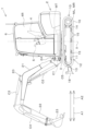
先ず、電動作業機1の全体構成について説明する。
図6は、電動作業機1の全体側面図である。
電動作業機1はバックホーである。電動作業機1は、機体(旋回台)2と走行装置10と作業装置20等を備えている。機体2の上には、作業者が着座する運転席4と、運転席4を前後、左右、及び上から保護する保護機構6が設けられている。
First, the overall configuration of the electric operating machine 1 will be described.
FIG. 6 is an overall side view of the electric operating machine 1. As shown in FIG.
The electric work machine 1 is a backhoe. The electric work machine 1 includes a machine body (swivel base) 2, a
保護機構6は、キャビンとも呼ばれている。保護機構6は、機体2に取り付けられたフレームと、フレームの上部に取り付けられたルーフと、フレームの前部、後部、及び左右側部にそれぞれ取り付けられた複数の側壁とを有している(詳細図示省略)。各側壁には、運転席4から周囲を目視可能な透明部分(いわゆる窓)が設けられている。このような保護機構6は、運転席4の周囲の空間と外部とを仕切っている。即ち、保護機構6により、運転席4を有する運転室4Rが形成されている。The
保護機構6の内部(運転室4R)の運転席4の周囲には、電動作業機1を操作するための操作装置5が設けられている。作業者は、運転席4に着座した状態で、操作装置5を操作可能である。An
なお、本実施形態においては、運転席4に着座した作業者の前側(図6の矢印A1方向)を前方、当該作業者の後側(図6の矢印A2方向)を後方として説明する。また、その前後方向に直交する水平方向を幅方向として説明する。さらに、運転席4に着座した作業者が前方A1に向いた状態で、左側を左方、作業者の右側を右方として説明する。In this embodiment, the front side of the operator seated in the driver's seat 4 (the direction of arrow A1 in FIG. 6) is described as the front, and the rear side of the operator (the direction of arrow A2 in FIG. 6) is described as the rear. The horizontal direction perpendicular to the front-to-rear direction is described as the width direction. Furthermore, when the operator seated in the driver's
走行装置10は、機体2を走行させる装置であって、走行フレーム11と走行機構12とを有する。走行フレーム(トラックフレーム)11は、周囲に走行機構12を取り付け、且つ上部に機体2を支持する構造体である。The
走行機構12は、例えばクローラ式の走行機構である。走行機構12は、走行フレーム11の左側と右側にそれぞれ設けられている。走行機構12は、アイドラ13と、駆動輪14と、複数の転輪15と、無端状のクローラベルト16と、走行モータ(左用走行モータML、右用走行モータMR)とを有している。The
アイドラ13は、走行フレーム11の前部に配置されている。駆動輪14は、走行フレーム11の後部に配置されている。複数の転輪15は、アイドラ13と駆動輪14との間に設けられている。クローラベルト16は、アイドラ13、駆動輪14、及び転輪15に亘って巻掛けられている。The
左用走行モータMLは、走行フレーム11の左側にある走行機構12に含まれている。右用走行モータMRは、走行フレーム11の右側にある走行機構12に含まれている。これら走行モータML、MRは、油圧モータから構成されている。各走行機構12では、走行モータML、MRの動力により、駆動輪14が回転駆動して、クローラベルト16を周方向に循環回走させる。
The left travel motor ML is included in the
走行装置10の前部には、ドーザ装置18が装着されている。ドーザ装置18は、ドーザシリンダC5の伸縮によって上下に揺動する。ドーザシリンダC5は、支持フレーム11に取り付けられている。ドーザシリンダC5は、油圧シリンダから構成されている。
A
機体2は、走行フレーム11上に旋回ベアリング3を介して、旋回軸心X回りに回転可能に支持されている。機体2の内部には、旋回モータMTが設けられている。旋回モータMTは、油圧モータ(油圧機器に含まれる油圧アクチュエータ)から構成されている。機体2は、旋回モータMTの動力により旋回軸心X回りに旋回する。The
作業装置20は、機体2の前部に支持されている。作業装置20は、ブーム21と、アーム22と、バケット(作業具)23と、油圧シリンダC1~C4を有する。ブーム21の基端側は、スイングブラケット24に横軸(機体2の幅方向に延伸する軸心)廻りに回動可能に枢着されている。このため、ブーム21は上下方向(鉛直方向)に揺動可能になっている。アーム22は、ブーム21の先端側に横軸廻りに回動可能に枢着されている。このため、アーム22は、前後方向或いは上下方向に揺動可能になっている。バケット23は、アーム22の先端側にスクイ動作及びダンプ動作が可能に設けられている。The
電動作業機1は、バケット23に代えて、或いは加えて、油圧アクチュエータにより駆動可能な他の作業具(油圧アタッチメント)を装着することが可能である。この他の作業具としては、油圧ブレーカ、油圧圧砕機、アングルブルーム、アースオーガ、パレットフォーク、スイーパー、モア、スノーブロア等が例示できる。The electric work machine 1 can be fitted with other work tools (hydraulic attachments) that can be driven by a hydraulic actuator instead of or in addition to the
スイングブラケット24は、機体2内に備えられたスイングシリンダC1の伸縮によって左右に揺動する。ブーム21は、ブームシリンダC2の伸縮によって上下(前後)に揺動する。アーム22は、アームシリンダC3の伸縮によって上下(前後)に揺動する。バケット23は、バケットシリンダ(作業具シリンダ)C4の伸縮によってスクイ動作及びダンプ動作を行う。スイングシリンダC1、ブームシリンダC2、アームシリンダC3、及びバケットシリンダC4は、油圧シリンダから構成されている。
The
作業機1は、上述した走行モータML、MRや油圧シリンダC1~C5を有する走行装置10や作業装置20や旋回モータMTにより作業を行う。走行モータML、MRや旋回モータMTや油圧シリンダC1~C5といった油圧アクチュエータは、油圧機器に含まれる。走行装置10も作業機1に備わる作業装置である。The work machine 1 performs work using the
次に、電動作業機1の電気的構成について説明する。
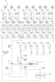
図1は、電動作業機1の電気ブロック図である。
電動作業機1の操作装置5は、操作レバー5aと操作スイッチ5bとを有している。操作レバー5aと操作スイッチ5bは、運転席4に着座した作業者が操作可能になっている。図1では、便宜上、操作レバー5aと操作スイッチ5bをそれぞれ1つのブロックで示しているが、実際には、操作レバー5aと操作スイッチ5bはそれぞれ複数設けられている。操作スイッチ5bには、モード切替スイッチ5cが含まれている。
Next, the electrical configuration of the electric operating machine 1 will be described.
FIG. 1 is an electrical block diagram of an electric operating machine 1.
The operating
制御装置7は、機体2又は保護機構6の内部に設けられていて、CPU7aと記憶部7bとを有している。CPU7aは、図1に示すような、電動作業機1に備わる各部の動作を制御する。記憶部7bはメモリ等から構成されている。CPU7aが各部の動作を制御するための情報、データ、及びプログラムなどは、記憶部7bに読み書き可能に記憶されている。The
スタータスイッチ8は、保護機構6の内部に設けられ、運転席4に着座した作業者が操作可能になっている。スタータスイッチ8は、電動作業機1を始動させたり停止させたりするために操作される。詳しくは、スタータスイッチ8をオン操作することで、制御装置7が電動作業機1に備わる各部を始動させる。また、スタータスイッチ8をオフ操作することで、制御装置7が電動作業機1に備わる各部を停止させる。The
電動モータ9は、電動作業機1の駆動源であって、例えば永久磁石埋込式の三相交流同期モータから構成されている。インバータ38は、電動モータ9を駆動させるモータ駆動装置である。インバータ38は、電動モータ9及びジャンクションボックス39と接続されている。The
ジャンクションボックス39は、インバータ38の他に、バッテリユニット30とDC-DCコンバータ40と充電口41とに接続されている。ジャンクションボックス39は、バッテリユニット30から出力された電力をインバータ38やDC-DCコンバータ40に出力する。In addition to the
インバータ38は、バッテリユニット30からジャンクションボックス39を経由して入力された直流電力を三相交流電力に変換し、当該三相交流電力を電動モータ9に供給する。これにより、電動モータ9が駆動する。また、インバータ38は、電動モータ9に供給する電力の電流や電圧を任意に調整可能である。制御装置7は、インバータ38の動作を制御して、電動モータ9を駆動させたり停止させたりする。The
DC-DCコンバータ40は、バッテリユニット30からジャンクションボックス39を経由して入力された直流電流の電圧を、異なる電圧に変換する電圧変換装置である。本実施形態では、DC-DCコンバータ40は、バッテリユニット30の高電圧を、電動作業機1に備わる電装品に応じた所定の低電圧に変換する降圧コンバータである。DC-DCコンバータ40は、電圧変換後に低圧バッテリ33へ電力を供給する。上記電装品には、例えば制御装置7や、後述するファンモータ35a、37a、42bやその他の装置41a、42、46~49等が含まれている。The DC-
充電口41は、充電ケーブル(図示省略)が嵌合されるコネクタ(図示省略)と、接続検出センサ41aとを有している。充電口41には、充電ケーブルを経由して外部電源(商用電源等)に接続される。接続検出装置41aは、充電口41に充電ケーブルが嵌合されて、外部電源が接続されたことを検出するセンサ等から成る。The charging
ジャンクションボックス39は、外部電源から充電ケーブルを経由して充電口41より入力された電力を、バッテリユニット30に出力する。バッテリユニット30は、その充電口41からジャンクションボックス39を経由して入力された電力で充電される。The
バッテリユニット30は、複数のバッテリパック31、32を有している。各バッテリパック31、32は、少なくとも1つのバッテリから構成されたリチウムイオン電池等の二次電池(蓄電池)である。各バッテリパック31、32を複数のバッテリから構成した場合、当該複数のバッテリは電気的に直列及び/又は並列に接続される。また、各バッテリパック31、32を構成するバッテリは、内部に複数のセルを有しており、当該複数のセルが電気的に直列及び/又は並列に接続されて構成されている。各バッテリパック31、32は、電動作業機1の各部を所定時間稼働可能な電気容量を有している。バッテリパック31、32同士は、並列に接続されている。The
本実施形態では、バッテリユニット30に2つのバッテリパック31、32を設けているが、バッテリユニット30が有するバッテリパックの数は2つに限定されず、3つ以上でもよい。In this embodiment, the
各バッテリパック31、32には、接続切替部31a、32aが設けられている。各接続切替部31a、32aは、例えばリレー又はスイッチ等から構成されていて、接続状態と遮断状態とに切り替わり可能である。Each
制御装置7は、接続切替部31a、32aのうち、一方の接続切替部を接続状態に切り替えて、他方の接続切替部を遮断状態に切り替えることにより、複数のバッテリパック31、32のうち、一方のバッテリパックからジャンクションボックス39に電力を出力し、他方のバッテリパックからの電力の出力を停止する。つまり、制御装置7は、各バッテリパック31、32の電力の出力と出力停止とを制御する。The
また、制御装置7は、ジャンクションボックス39の内部の接続状態を切り替えて、各バッテリパック31、32に対してインバータ38、DC-DCコンバータ40、又は充電口41を接続したり切断したりする。ジャンクションボックス39と接続切替部31a、32aとは、各バッテリパック31、32に対するインバータ38、DC-DCコンバータ40、及び充電口41の接続と切断とを切り替える接続切替装置である。
The
また、各バッテリパック31、32には、BMU(battery management unit;バッテリ監視装置)31b、32bが設けられている。図1では、BMU31b、32bは対応するバッテリパック31、32内に設けられているが、BMU31b、32bは対応するバッテリパック31、32に内蔵されていてもよいし、又はバッテリパック31、32の外側に設置されていてもよい。In addition, each
BMU31bは、対応するバッテリパック31を監視及び制御する。BMU32bは、対応するバッテリパック32を監視及び制御する。具体的には、BMU31b、32bは、バッテリパック31、32の内部に備わるリレーの開閉を制御して、バッテリパック31、32からの電力供給の開始及び停止を制御する。また、BMU31b、32bは、バッテリパック31、32の温度、電圧、電流、又は内部のセルの端子電圧等を検出する。
さらに、BMU31b、32bは、例えばバッテリパック31、32の内部のセルの端子電圧に基づいて、電圧測定方式によりバッテリパック31、32の残容量を検出する。なお、バッテリパック31、32の残容量の検出方法は、電圧測定方式に限定されず、クーロン・カウンタ方式、電池セル・モデリング方式、インピーダンス・トラック方式などのような他の方式であってもよい。また、バッテリパック31、32の残容量を検出する容量検出部を、BMU31b、32bとは別に設けてもよい。
Furthermore, the
低圧バッテリ33は、バッテリユニット30より低電圧の蓄電池である。低圧バッテリ33は、DC-DCコンバータ40から供給される電力により充電される。低圧バッテリ33は、電動作業機1に備わる電装品に電力を供給する。容量検出装置34は、低圧バッテリ33の残容量を検出する電気回路から成る。
The low-
ラジエータ35は、電動モータ9、インバータ38、DC-DCコンバータ40、及びバッテリユニット30等の高発熱型の電気機器を冷却するための冷却水を冷却する。高発熱型の電気機器とは、電力で動作することにより、電動作業機1に備わる他の電気機器より高い熱を発する電気機器のことである。冷却水は、単なる水ではなく、例えば寒冷地でも凍らないような液体から構成されている。
The
ラジエータ35は、ファンモータ35aと、当該ファンモータ35aの動力により回転駆動するラジエータファン35f及び熱交換部35b(後述の図3に図示)を有している。ファンモータ35aは、低圧バッテリ33の電力で駆動する。The
冷却用ポンプ36は、ラジエータ35及び上記の高発熱型の電気機器と共に、機体2内に配設された冷却水路(図示省略)に設けられている。冷却用ポンプ36は、その冷却水路に対して冷却水を吐出及び循環させる。The cooling
オイルクーラ37は、前述した油圧アクチュエータML、MR、MT、C1~C5や、後述する油圧ポンプP1、P2及びコントロールバルブV(図2等に図示)といった油圧機器を通過した作動油を冷却する。オイルクーラ37は、ファンモータ37aと、当該ファンモータ37aの動力により回転駆動するオイルクーラファン37f及び熱交換部37b(後述の図3に図示)を有している。ファンモータ37aは、低圧バッテリ33の電力で駆動する。The
電動暖房装置42は、低圧バッテリ33の電力により駆動して、保護機構6の内部の暖房を行う。電動暖房装置42は、電気ヒータから構成され、電熱線42aとファンモータ42bと暖房ファン(図示省略)を有している。電熱線42aは、通電されることにより高熱を発する。ファンモータ42bは、暖房ファンを回転駆動させる。暖房ファンは、電熱線42aにより暖められた周囲の空気を保護機構6の内部に向かって送風する。ファンモータ42bは、低圧バッテリ33の電力で駆動する。The
電動冷房装置46は、例えばエアコンから構成されている。電動冷房装置46は、低圧バッテリ33の電力により駆動して、保護機構6の内部の冷房を行う。電動暖房装置42と電動冷房装置46とは、保護機構6の内部の空調を行う空調装置である。The
油温検出装置47は、作動油の温度(油温)を検出するセンサから成る。室温検出装置48は、保護機構6の内部の温度(室温)を検出するセンサから成る。水温検出装置49は、冷却水の温度(水温)を検出するセンサから成る。
The oil
次に、電動作業機1に備わる油圧回路について説明する。
図2は、電動作業機1に備わる油圧回路Kを示した図である。
油圧回路Kには、油圧アクチュエータC1~C5、ML、MR、MT、コントロールバルブV、油圧ポンプP1、P2、作動油タンクT、オイルクーラ37、操作弁PV1~PV6、アンロード弁58、及び油路50等の油圧機器が設けられている。
Next, a hydraulic circuit provided in the electric work machine 1 will be described.
FIG. 2 is a diagram showing a hydraulic circuit K provided in the electric working machine 1.
The hydraulic circuit K is provided with hydraulic devices such as hydraulic actuators C1 to C5, ML, MR, MT, a control valve V, hydraulic pumps P1, P2, a hydraulic oil tank T, an
複数設けられた油圧ポンプP1、P2のうち、一方は作動用油圧ポンプP1であり、他方はコントロール用油圧ポンプP2である。これらの油圧ポンプP1、P2は、電動モータ9の動力により駆動する。Of the multiple hydraulic pumps P1 and P2, one is the actuation hydraulic pump P1 and the other is the control hydraulic pump P2. These hydraulic pumps P1 and P2 are driven by the power of an
作動用油圧ポンプP1は、作動油タンクTに貯留された作動油を吸引した後、コントロールバルブVに向かって作動油を吐出する。図2では、便宜上、作動用油圧ポンプP1を1つ図示しているが、これに限らず、各油圧アクチュエータC1~C5、ML、MR、MTに作動油を供給可能に作動用油圧ポンプP1を適宜数設ければよい。The hydraulic pump P1 draws hydraulic oil stored in the hydraulic oil tank T and then discharges the hydraulic oil toward the control valve V. For convenience, one hydraulic pump P1 is shown in FIG. 2, but this is not limiting and an appropriate number of hydraulic pumps P1 may be provided to supply hydraulic oil to each hydraulic actuator C1-C5, ML, MR, and MT.
コントロール用油圧ポンプP2は、作動油タンクTに貯留された作動油を吸引した後吐出することにより、信号用又は制御用等の油圧を出力する。即ち、コントロール用油圧ポンプP2はパイロット油を供給(吐出)する。コントロール用油圧ポンプP2も適宜数設ければよい。The control hydraulic pump P2 outputs hydraulic pressure for signals or controls by drawing in and then discharging hydraulic oil stored in the hydraulic oil tank T. In other words, the control hydraulic pump P2 supplies (discharges) pilot oil. An appropriate number of control hydraulic pumps P2 may be provided.
コントロールバルブVは、複数の制御弁V1~V8を有している。各制御弁V1~V8は、油圧ポンプP1、P2から各油圧アクチュエータC1~C5、ML、MR、MTに出力する作動油の流量を制御(調整)を調整する。 The control valve V has multiple control valves V1 to V8. Each control valve V1 to V8 controls (adjusts) the flow rate of hydraulic oil output from the hydraulic pumps P1 and P2 to each hydraulic actuator C1 to C5, ML, MR, and MT.
具体的には、スイング制御弁V1は、スイングシリンダC1に供給する作動油の流量を制御する。ブーム制御弁V2は、ブームシリンダC2に供給する作動油の流量を制御する。アーム制御弁V3は、アームシリンダC3に供給する作動油の流量を制御する。バケット制御弁V4は、バケットシリンダC4に供給する作動油の流量を制御する。ドーザ制御弁V5は、ドーザシリンダC5に供給する作動油の流量を制御する。左用走行制御弁V6は、左用走行モータMLに供給する作動油の流量を制御する。右用走行制御弁V7は、右用走行モータMRに供給する作動油の流量を制御する。旋回制御弁V8は、旋回モータMTに供給する作動油の流量を制御する。 Specifically, the swing control valve V1 controls the flow rate of hydraulic oil supplied to the swing cylinder C1. The boom control valve V2 controls the flow rate of hydraulic oil supplied to the boom cylinder C2. The arm control valve V3 controls the flow rate of hydraulic oil supplied to the arm cylinder C3. The bucket control valve V4 controls the flow rate of hydraulic oil supplied to the bucket cylinder C4. The dozer control valve V5 controls the flow rate of hydraulic oil supplied to the dozer cylinder C5. The left travel control valve V6 controls the flow rate of hydraulic oil supplied to the left travel motor ML. The right travel control valve V7 controls the flow rate of hydraulic oil supplied to the right travel motor MR. The swing control valve V8 controls the flow rate of hydraulic oil supplied to the swing motor MT.
操作弁PV1~PV6は、操作装置5に備わる各種の操作レバー5a(図1)の操作に応じて作動する。各操作弁PV1~PV6の作動量(操作量)に比例して、パイロット油が各制御弁V1~V8に作用することで、各制御弁V1~V8のスプールが動かされる。そして、各制御弁V1~V8のスプールの動かされた量に比例する量の作動油が、制御対象の油圧アクチュエータC1~C5、ML、MR、MTに供給される。さらに、各油圧アクチュエータC1~C5、ML、MR、MTが、各制御弁V1~V8からの作動油の供給量に応じて駆動する。
The control valves PV1 to PV6 operate in response to the operation of
言い換えれば、操作レバー5aが操作されることで、制御弁V1~V8に作用する作動油(パイロット油)が調整されて、制御弁V1~V8が制御される。そして、制御弁V1~V8から油圧アクチュエータC1~C5、ML、MR、MTに供給される作動油の量が調整されて、油圧アクチュエータC1~C5、ML、MR、MTの駆動と停止とが制御される。In other words, by operating the operating
油路50は、例えばホース又は金属等の材料で形成された管から構成されている。油路50は、油圧回路Kに設けられた各部を接続し、各部に対して作動油又はパイロット油を流す流路である。油路50には、第1油路51、第2油路52、第1吸引油路54、第2吸引油路55、及び制限油路57が含まれている。The
第1吸引油路54は、作動用油圧ポンプP1が作動油タンクTから吸引した作動油を流す流路である。第2吸引油路55は、コントロール用油圧ポンプP2が作動油タンクTから吸引した作動油を流す流路である。The first
第1油路51は、作動用油圧ポンプP1が吐出した作動油をコントロールバルブVの制御弁V1~V8に向かって流す流路である。第1油路51は、コントロールバルブV内で複数に分岐して、各制御弁V1~V8に接続されている。The
第2油路52は、制御弁V1~V8を通過した作動油を作動油タンクTに向かって流す流路である。作動油タンクTは作動油を貯留する。第2油路52には、往復油路52aと排出油路52bとが含まれている。
The
往復油路52aは、各制御弁V1~V8と制御対象の油圧アクチュエータC1~C5、ML、MR、MTとを2本1対で接続するように複数設けられている。往復油路52aは、接続された制御弁V1~V8から油圧アクチュエータC1~C5、ML、MR、MTに作動油を供給したり、油圧アクチュエータC1~C5、ML、MR、MTから制御弁V1~V8に作動油を戻したりする流路である。排出油路52bの一端側は複数に分岐して、各制御弁V1~V8に接続されている。排出油路52bの他端部は、作動油タンクTに接続されている。
Multiple
第1油路51を通っていずれかの制御弁V1~V8に流れた作動油の一部は、当該制御弁V1~V8を通過して往復油路52aの一方を通り、制御対象の油圧アクチュエータC1~C5、ML、MR、MTに供給される。そして、その油圧アクチュエータC1~C5、ML、MR、MTから排出された作動油は、往復油路52aの他方を通って接続された制御弁V1~V8に戻り、当該制御弁V1~V8を通過して、排出油路52b流れる。A portion of the hydraulic oil that flows through the
また、第1油路51を通っていずれかの制御弁V1~V8に流れた作動油の他部は、油圧アクチュエータC1~C5、ML、MR、MTへ供給されることなく、当該制御弁V1~V8を通過して排出油路52bに流れる。排出油路52bには、オイルクーラ37が設けられている。オイルクーラ37は、いずれかの制御弁V1~V8から排出油路52bを通って流れて来た作動油を冷却する。
The other part of the hydraulic oil that flows through the
オイルクーラ37で冷却された作動油は、排出油路52bを通って作動油タンクTに戻る。上述したように、油路54、51、52は、作動油を作動油タンクTと油圧ポンプP1とコントロールバルブVの制御弁V1~V8と(一部の作動油は油圧アクチュエータC1~C5、ML、MR、MTも)に対して循環させるように配設されている。The hydraulic oil cooled by the
制限油路57は、コントロール用油圧ポンプP2が吐出した作動油を操作弁PV1~PV6に流す流路である。制限油路57の一端部は、コントロール用油圧ポンプP2に接続され、他端側は複数に分岐して、各操作弁PV1~PV6の一次側のポート(一次ポート)に接続されている。The
制限油路57には、アンロード弁58が設けられている。アンロード弁58は、作動用油圧ポンプP1から油圧アクチュエータC1~C5、ML、MR、MTに対する作動油の供給を遮断することにより、油圧アクチュエータC1~C5、ML、MR、MTの駆動、即ち作業装置20の駆動を禁止又は制限する。An unloading
詳しくは、アンロード弁58は、操作レバー5aに含まれるアンロードレバー(図示省略)を操作することにより、供給位置と遮断位置とに切り換えられる。アンロード弁58が供給位置に切り替わることで、コントロール用油圧ポンプP2から制限油路57に吐出された作動油が操作弁PV1~PV6に供給されて、制御弁V1~V8の操作が可能になる。またこれにより、油圧アクチュエータC1~C5、ML、MR、MT、作業装置20、及び走行装置10の操作も可能となる。操作弁PV1~PV6から排出された作動油は、別の排出油路(図示省略)を通って作動油タンクTに戻る。
In more detail, the unloading
対して、アンロード弁58が遮断位置に切り替わることで、コントロール用油圧ポンプP2から制限油路57に吐出された作動油が作動油タンクTに排出されて、操作弁PV1~PV6に供給されなくなり(供給停止)、制御弁V1~V8の操作が禁止又は制限される。またこれにより、油圧アクチュエータC1~C5、ML、MR、MT、作業装置20、及び走行装置10の操作も禁止又は制限される。On the other hand, when the unloading
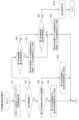
次に、電動作業機1の機体2内の配置を説明する。
図3は、電動作業機1の機体2内の配置例を示した図である。図3では、機体2の内部を上方から見た状態を示している。機体2内において、コントロールバルブVは、旋回ベアリング3の前側(A1方向側)に配置されている。作動油タンクTは、旋回ベアリング3の右側で且つスイングシリンダC1の上方に配置されている。旋回ベアリング3の後方A2には、仕切り板80が機体2の幅方向と平行に設けられている。仕切り板80は、機体2の内部空間を前後に仕切っている。
Next, the layout inside the
Fig. 3 is a diagram showing an example of the layout inside the
仕切り板80の後ろ側(A2方向側)には、後部ルームRが設けられている。後部ルームR内には、バッテリユニット30、インバータ38、ジャンクションボックス39、DC-DCコンバータ40、油圧ポンプP1、P2、電動モータ9、ラジエータ35、オイルクーラ37等が設けられている。A rear room R is provided behind the partition plate 80 (A2 direction side). In the rear room R, a
バッテリユニット30が有するバッテリパック31、32は、機体2の幅方向に並べて配置されている。インバータ38、ジャンクションボックス39、及びDC-DCコンバータ40は、バッテリパック31、32の上方に配置されている。The battery packs 31, 32 of the
油圧ポンプP1、P2、電動モータ9、ラジエータ35、及びオイルクーラ37は、バッテリユニット30の右側に配置されている。電動モータ9は、油圧ポンプP1、P2の後ろ側に配置されている。ラジエータ35は、電動モータ9の上方に配置されている。ラジエータ35の熱交換部35bは、ラジエータファン35fよりバッテリユニット30側に配置されている。オイルクーラ37は、油圧ポンプP1、P2の上方に配置されている。オイルクーラ37の熱交換部37bは、オイルクーラファン37fよりバッテリユニット30側に配置されている。
The hydraulic pumps P1, P2,
仕切り板80には、複数の貫通孔81、82、83が形成されている。貫通孔81、82、83には、例えば、油路50を構成するホース(図示省略)や電気配線等が挿通される。また、貫通孔81、82、83を通気口として使用してもよい。機体2の上方には、保護機構6(運転室4R)が搭載されている。The
次に、電動作業機1の動作を説明する。
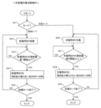
図4A及び図4Bは、電動作業機1の充放電対象決定動作を示したフローチャートである。図4A及び図4B示す一連の処理は、図1の制御装置7の記憶部7bに予め記憶されたソフトウェアプログラムに基づいて、CPU7aにより所定の周期で繰り返し実行される。また、図4A及び図4Bでは、便宜上、バッテリパックを「BP」と示し、一方のバッテリパック31を「第1BP」と示し、他方のバッテリ32を「第2BP」と示している(後述の図5も同様)。
Next, the operation of the electric operating machine 1 will be described.
Figures 4A and 4B are flow charts showing the operation of determining a charge/discharge target of the electric operating machine 1. A series of processes shown in Figures 4A and 4B are repeatedly executed at a predetermined cycle by the
例えば、バッテリユニット30で放電と充電とが行われていないときに(電動モータ9(図1)は停止中)、又はスタータスイッチ8(図1)がオン操作されたときに、制御装置7は、BMU31b、32b(図1)によるバッテリパック31、32の監視結果を比較する(図4AのS1)。そして、その比較結果から、制御装置7は、全てのバッテリパック31、32の異常(エラー)の有無を確認する。For example, when the
なお、バッテリパック31、32の異常の有無は、例えばBMU31b、32bが、バッテリパック31、32の電圧、電流、内部のセルの端子電圧、又は温度等を検出した結果に基づいて判断して、制御装置7に通知する。他の例として、BMU31b、32bから送信されたバッテリパック31、32の電圧、電流、内部のセルの端子電圧、又は温度等のデータに基づいて、制御装置7がバッテリパック31、32の異常の有無を判断してもよい。また、制御装置7が、BMU31b、32bと正常に通信できない場合にも、バッテリパック31、32に異常が有ると判断してよい。The presence or absence of an abnormality in the battery packs 31, 32 is determined, for example, by the
例えば制御装置7は、全てのバッテリパック31、32に異常が無いことを確認する(S2:YES)。この場合、制御装置7は、BMU31b、32bにより監視されたバッテリパック31、32の残容量を比較する。For example, the
そして、第1バッテリパック31の残容量が第2バッテリパック32の残容量以上であれば(S3:YES)、制御装置7は、残容量が多い第1バッテリパック31を放電用バッテリパックとして決定し、残容量が少ない第2バッテリパック32を充電用バッテリパックとして決定する(S4)。この決定内容は、例えばCPU7aの内部メモリ(又は記憶部7b)に記録される。If the remaining capacity of the
また、第1バッテリパック31の残容量が第2バッテリパック32の残容量より少なければ(S3:NO)、制御装置7は、残容量が多い第2バッテリパック32を放電用バッテリパックとして決定し、残容量が少ない第1バッテリパック31を充電用バッテリパックとして決定する(S5)。この決定内容も、CPU7aの内部メモリ等に記録される。If the remaining capacity of the
一方、例えば制御装置7は、いずれかのバッテリパック31、32に異常が有って(S2:NO)、そのうち第1バッテリパック31に異常が無く、第2バッテリパック32に異常が有ることを確認する(S6:YES)。この場合、制御装置7は、第1バッテリパック31を、放電モードでは放電用バッテリパック、充電モードでは充電用バッテリパックとすることを決定する(S7)。この決定内容も、CPU7aの内部メモリ等に記録される。On the other hand, for example, the
また、例えば制御装置7は、いずれかのバッテリパック31、32に異常が有って(S2:NO)、そのうち第1バッテリパック31に異常が有り、第2バッテリパック32に異常が無いことを確認する(S6:NO、S8:YES)。この場合、制御装置7は、第2バッテリパック32を、放電モードでは放電用バッテリパック、充電モードでは充電用バッテリパックとすることを決定する(S9)。この決定内容も、CPU7aの内部メモリ等に記録される。In addition, for example, if there is an abnormality in either of the battery packs 31, 32 (S2: NO), the
また、例えば制御装置7は、全てのバッテリパック31、32に異常が有ることを確認すると(S2:NO、S6:NO、S8:NO)、全てのバッテリパック31、32が使用不可であると判断する(S10)。この判断内容は、CPU7aの内部メモリ等に記録される。この場合、その後に放電モードに移行しても、バッテリパック31、32が放電されることはない。また、その後に充電モードに移行しても、バッテリパック31、32が充電されることはない。
For example, when the
処理S4、S5、S7、又はS9の後、制御装置7は、バッテリパック31、32のいずれかで放電を行う放電モードにあるか、又はバッテリパック31、32のいずれかの充電を行う充電モードにあるかを判断する。After process S4, S5, S7, or S9, the
このとき、例えば制御装置7は、充電口41に充電ケーブルが接続されている場合に、充電モードにあると判断し、充電口41に充電ケーブルが接続されていない場合に、放電モードと判断してもよい。あるいは、制御装置7は、モード切替スイッチ5c(図1)に対して放電モード又は充電モードへの切り替え指示の入力が有るか否かの確認結果に基づいて、放電モードにあるか充電モードにあるかを判断してもよい。この場合、作業者は、モード切替スイッチ5cで所定の操作を行って、放電モード又は充電モードへの切り替えを指示する。At this time, for example, the
また他の例として、例えば制御装置7は、スタータスイッチ8でオン操作(電動作業機1の始動操作)が行われた場合に、放電モードにあると判断し、オン操作が行われていない場合に、充電モードにあると判断してもよい。また、制御装置7は、作業装置20や走行装置10を操作する操作レバー5aや操作スイッチ5b(図1)に対する操作状態に基づいて、放電モードにあるか充電モードにあるかを判断してもよい。As another example, the
制御装置7は、バッテリパック31、32のいずれかで放電を行う放電モードにあると判断した場合(図4BのS11:YES)、接続切替部31a、32aとジャンクションボックス39(図1)を制御して、複数のバッテリパック31、32のうち、既に決定した放電用バッテリパックの電力をインバータ38とDC-DCコンバータ40(図1)に供給(放電)する(S12)。When the
具体的には、例えば処理S4又はS7で第1バッテリパック31が放電用バッテリパックとして決定された場合、処理S12で制御装置7は、接続切替部31aを接続状態にし、接続切替部32aを切断状態にし、さらにジャンクションボックス39の内部の接続状態を切り替えて、第1バッテリパック31の内部のバッテリを放電して、当該バッテリの電力をインバータ38とDC-DCコンバータ40に供給する。
Specifically, for example, if the
また、例えば処理S5又はS9で第2バッテリパック32が放電用バッテリパックとして決定された場合、処理S12で制御装置7は、接続切替部32aを接続状態にし、接続切替部31aを切断状態にし、さらにジャンクションボックス39の内部の接続状態を切り替えて、第2バッテリパック32の内部のバッテリを放電して、当該バッテリの電力をインバータ38とDC-DCコンバータ40に供給する。
Furthermore, for example, if the
そして、制御装置7は、インバータ38を制御して、インバータ38から電動モータ9に電力を供給して、電動モータ9を駆動する(S13)。これにより、油圧ポンプP1、P2、コントロールバルブVの制御弁V1~V8、油圧アクチュエータC1~C5、ML、MR、MT、アンロード弁58、及び操作弁PV1~PV6といった油圧機器が駆動可能になり、さらに作業装置20と走行装置10が作動可能になる。The
また、制御装置7は、DC-DCコンバータ40を制御して、DC-DCコンバータ40から低圧バッテリ33(図1)に電力を供給して、低圧バッテリ33を随時充電する(S14)。これにより、電動作業機1に備わる電装品を駆動するための電力が、低圧バッテリ33に確保される。The
その後、例えば運転者がスタータスイッチ8をオフ操作すると、制御装置7は、電動モータ9の停止が指示されたと判断し、接続切替部31a、32aとジャンクションボックス39を制御して、放電用バッテリパックからインバータ38や電動モータ9やDC-DCコンバータ40への電力供給を停止する。これにより、放電モードが終了して、電動モータ9が停止し、上述した油圧機器P1、P2、V(V1~V8)、C1~C5、ML、MR、MT、58、PV1~PV6が停止し、作業装置20と走行装置10も停止する。このとき、制御装置7は、放電用バッテリパック又は充電用バッテリパックの決定を解除、即ち、CPU7aの内部メモリ等に記録されたバッテリパック31、32の用途の決定内容を消去してもよい。この後、制御装置7は、再び処理S1から以降の処理を実行する。
After that, for example, when the driver turns off the
一方、処理S4、S5、S7、又はS9の後、制御装置7は、バッテリパッ31、32のいずれかで充電を行う充電モードにあると判断した場合(S15:YES)、接続切替部31a、32aとジャンクションボックス39を制御して、外部電源から充電ケーブルを経由して充電口41に入力された電力を、さらに充電用バッテリパックに入力して、充電用バッテリパックを充電する(S16)。On the other hand, after processing S4, S5, S7, or S9, if the
具体的には、例えば処理S5又はS7で第1バッテリパック31が充電用バッテリパックとして決定された場合、処理S16で制御装置7は、接続切替部31aを接続状態にし、接続切替部32aを切断状態にし、さらにジャンクションボックス39の内部の接続状態を切り替えて、外部電源から充電口41に入力された電力を第1バッテリパック31に入力して、第1バッテリパック31の内部のバッテリを充電する。Specifically, for example, if the
また、例えば処理S4又はS9で第2バッテリパック32が充電用バッテリパックとして決定された場合、処理S16制御装置7は、接続切替部32aを接続状態にし、接続切替部31aを切断状態にし、さらにジャンクションボックス39の内部の接続状態を切り替えて、外部電源から充電口41に入力された電力を第2バッテリパック32に入力して、第2バッテリパック32の内部のバッテリを充電する。
Furthermore, for example, if the
その後、例えば充電用バッテリパックが所定容量まで充電されたことがBMU31b、32bから通知されると、制御装置7は、接続切替部31a、32aとジャンクションボックス39を制御して、外部電源から充電口41に入力された電力が充電用バッテリパックに入力されるのを遮断し、充電モードが終了する。このとき、制御装置7は、充電用バッテリパック又は放電用バッテリパックの決定を解除、即ち、CPU7aの内部メモリ等に記録されたバッテリパック31、32の用途の決定内容を消去してもよい。この後、制御装置7は、再び処理S1から以降の処理を実行する。
After that, for example, when the
図4A及び図4Bに示した実施形態では、放電用バッテリパック又は充電用バッテリパックを決定してから、放電モード又は充電モードを判断しているが、逆に、放電モード又は充電モードを判断してから、放電用バッテリパック又は充電用バッテリパックを決定してもよい。また、例えばスタータスイッチ8のオン操作時又はオフ操作時に、放電用バッテリパック又は充電用バッテリパックを決定してもよい。In the embodiment shown in Figures 4A and 4B, the discharge battery pack or the charge battery pack is determined, and then the discharge mode or the charge mode is determined. However, conversely, the discharge battery pack or the charge battery pack may be determined after the discharge mode or the charge mode is determined. Also, for example, the discharge battery pack or the charge battery pack may be determined when the
また、図4Aの処理S4、S5、S7、及びS9では、放電用バッテリパックと充電用バッテリパックとを両方とも決定しているが、これに代えて、放電用と充電用のうち一方の動作用バッテリパックだけ決定してもよい。 In addition, in processes S4, S5, S7, and S9 of FIG. 4A, both a discharge battery pack and a charge battery pack are determined, but instead, only one of the discharge and charge operating battery packs may be determined.
また、図4A及び図4Bに示した実施形態では、バッテリパック31、32の異常の有無や残容量に基づいて、放電用バッテリパック又は充電用バッテリパックを決定している。然るに、これら以外に、例えばBMU31b、32bが監視するバッテリパック31、32の電圧、電流、内部のセルの端子電圧、又は温度等を比較した結果に基づいて、制御装置7が放電用バッテリパック又は充電用バッテリパックを決定してもよい。4A and 4B, the battery pack to be discharged or the battery pack to be charged is determined based on the presence or absence of an abnormality and the remaining capacity of the battery packs 31, 32. However, in addition to these, the
また、例えばBMU31b、32bや制御装置7がバッテリパック31、32の劣化度や使用履歴(主に使用頻度)を監視し、その監視結果を比較した結果に基づいて、制御装置7が放電用バッテリパック又は充電用バッテリパックを決定してもよい。さらに、上述したバッテリパック31、32の監視パラメータ(電圧、電流、内部のセルの端子電圧、温度、エラーの有無、残容量、劣化度、使用履歴)のうち、2つ以上を比較した結果に基づいて、制御装置7が放電用バッテリパック又は充電用バッテリパックを決定してもよい。
For example, the
図5は、電動作業機1の充放電対象切替動作を示したフローチャートである。
前述したように制御装置7は、放電モードにあると判断すると(S21:放電モード)、インバータ38とDC-DCコンバータ40(図1)に電力を供給するため、放電用バッテリパック(バッテリパック31、32のうちいずれか一方)を放電する(S22)。この放電中、制御装置7は、BMU31b、32bにより監視される放電用バッテリパックの残容量を所定の周期で確認する。そして、放電用バッテリパックの残容量が所定の第1閾値以下に低下すると(S23:YES)、制御装置7は、BMU31b、32bにより監視される他のバッテリパックの残容量を確認し、放電用バッテリパックを他のバッテリパックのうち残容量が最も多いバッテリパック(バッテリパック31、32のうちいずれか他方)に切り替える(S24)。
FIG. 5 is a flowchart showing the charging/discharging target switching operation of the electric operating machine 1.
As described above, when the
なお、上記第1閾値は、例えば、電動作業機1を安全な姿勢に移行させるのに要する電力量、放電用バッテリパックを他のバッテリパックへ切り替えるのに要する電力量、充電準備が整う場所への電動作業機1の移動に要する電力量等を考慮して、適宜設定してもよく、又はゼロに設定してもよい。
処理S24の際、例えば制御装置7は、BMU31b、32bにより、放電用バッテリパックとして使用していたバッテリパックの放電を停止してから、接続切替部31a、32aとジャンクションボックス39を制御して、インバータ38とDC-DCコンバータ40への電力の供給元を新たに放電用バッテリパックとなったバッテリパックに切り替える。そして、制御装置7は、インバータ38とDC-DCコンバータ40に電力を供給するため、新たな放電用バッテリパックを放電する(S22)。放電用バッテリパックの放電は、放電モードが終了されない(S25:NO)限り継続される。
The first threshold value may be set appropriately taking into consideration, for example, the amount of power required to move the electric work machine 1 to a safe position, the amount of power required to switch the discharge battery pack to another battery pack, and the amount of power required to move the electric work machine 1 to a location ready for charging, or may be set to zero.
In process S24, for example, the
一方、前述したように制御装置7は、充電モードにあると判断すると(S21:充電モード)、外部電源から充電口41等を介して入力された電力で充電用バッテリパックを充電する(S26)。この充電中、制御装置7は、BMU31b、32bにより監視される放電用バッテリパックの残容量を所定の周期で確認する。そして、放電用バッテリパックの残容量が所定の第2閾値以上になると(S27:YES)、制御装置7は、BMU31b、32bにより監視される他のバッテリパックの残容量を確認し、放電用バッテリパックを他のバッテリパックのうち残容量が最も少ないバッテリパックに切り替える(S28)。On the other hand, as described above, when the
なお、上記第2閾値は、充電するバッテリパック31、32の満充電状態に相当する値に設定してもよく、又はバッテリパック31、32の充放電特性等に応じて適宜設定してもよい。 The second threshold value may be set to a value corresponding to the fully charged state of the battery packs 31, 32 to be charged, or may be set appropriately depending on the charging and discharging characteristics of the battery packs 31, 32, etc.
処理S28の際、例えば制御装置7は、BMU31b、32bにより、充電用バッテリパックとして使用していたバッテリパックの充電を停止してから、接続切替部31a、32aとジャンクションボックス39を制御して、外部電源から電力の入力先を新たに充電用バッテリパックとなったバッテリパックに切り替える。そして、制御装置7は、外部電源から入力された電力で新たな充電用バッテリパックを充電する(S26)。充電用バッテリパックの充電は、充電モードが終了されない(S29:NO)限り継続される。During process S28, for example, the
以上の実施形態では、電動作業機1に2つのバッテリパック31、32を搭載した場合を例に挙げているが、これに代えて、3つの以上のバッテリパックを電動作業機1に搭載してもよい。この場合、例えば、異常の無いバッテリパックのうち、最も残容量が多いバッテリパックを放電用バッテリパックとして決定すればよい。また、それ以外の残りバッテリパックのうち、少なくとも1つの正常なバッテリパックを充電用バッテリパックとして決定したり、又は最も残容量が少ないバッテリパックを充電用バッテリパックとして決定したりすればよい。In the above embodiment, an example is given in which two battery packs 31, 32 are mounted on the electric work machine 1, but instead, three or more battery packs may be mounted on the electric work machine 1. In this case, for example, the battery pack with the greatest remaining capacity among the battery packs without abnormalities may be determined as the battery pack for discharging. Furthermore, at least one normal battery pack among the remaining battery packs may be determined as the battery pack for charging, or the battery pack with the least remaining capacity may be determined as the battery pack for charging.
また、例えば放電モードでは、過電流による故障を防止する等のため、1つの電力供給先の電気機器に複数のバッテリパックの電力を同時に供給しないようにするのが好ましい。また、充電モードでは、外部電源から同一の給電配線を通して複数のバッテリパックに電力を入力しないようにするのが好ましい。In addition, for example, in the discharge mode, it is preferable not to simultaneously supply power from multiple battery packs to one power destination electrical device in order to prevent breakdowns due to overcurrent. In addition, in the charge mode, it is preferable not to input power from an external power source to multiple battery packs through the same power supply wiring.
さらに、以上の実施形態では、バッテリパック31、32からの電力で電動モータ9を駆動させ、電動モータ9の動力で油圧ポンプP1、P2を駆動させ、油圧ポンプP1、P2から吐出される作動油により油圧アクチュエータC1~C5、ML、MR、MTを駆動させ、油圧アクチュエータC1~C5、ML、MR、MTの動力で作業装置20、10を駆動させる構成について説明したが、これに限るものではない。例えば、作業装置20、10に備えるアクチュエータのうち一部又は全部を電動アクチュエータで構成し、当該電動アクチュエータをバッテリパック31、32の電力で駆動させて、当該電動アクチュエータの動力で作業装置20、10を駆動させる構成にしてもよい。
Furthermore, in the above embodiment, the
本実施形態の電動作業機1は、以下の効果を奏する。
本実施形態の電動作業機1は、複数のバッテリパック31、32と、バッテリパック31、32から放電される電力により駆動する作業装置20、10(作業装置20、走行装置10)と、各バッテリパック31、32の状態を監視するバッテリ監視装置(BMU)31b、32bと、バッテリパック31、32の充電および放電を制御する制御装置7と、を備え、制御装置7は、作業装置20、10を駆動する放電モードでは、バッテリ監視装置31b、32bによる各バッテリパック31、32の監視結果に基づいて、複数のバッテリパック31、32のうちいずれか1つを作業装置20、10に電力を供給するために放電する放電用バッテリパックとして決定し、バッテリパック31、32の充電を行う充電モードでは、バッテリ監視装置31b、32bによる各バッテリパック31、32の監視結果に基づいて、複数のバッテリパック31、32のうちいずれか1つを充電する充電用バッテリパックとして決定する。
The electric operating machine 1 of this embodiment provides the following effects.
The electric work machine 1 of this embodiment includes a plurality of battery packs 31, 32,
上記の構成によれば、放電モード及び充電モードのそれぞれにおいて、各バッテリパック31、32の状態に基づいて、放電モードや充電モードに適したバッテリパックを選択することができるので、複数のバッテリパックを効率良く使用することが可能となる。
According to the above configuration, in each of the discharge mode and the charge mode, a battery pack suitable for the discharge mode or the charge mode can be selected based on the state of each
また、バッテリ監視装置31b、32bは、各バッテリパック31、32の残容量を監視し、制御装置7は、放電モードでは、複数のバッテリパック31、32のうち残容量が最も多いバッテリパックを放電用バッテリパックとして決定する。これにより、単一のバッテリパックの電力で作業を行う時間を長く確保することができ、バッテリパックの切り替え等による作業中断時間を削減して、効率良く作業を行うことが可能となる。
The
また、制御装置7は、放電モードにおいて、放電用バッテリパックとして使用しているバッテリパックの残容量が第1閾値以下に低下したときに、放電用バッテリパックを他のバッテリパックのうち残容量が最も多いバッテリパックに切り替える。これにより、放電するバッテリパック31、32の切り替え頻度を低減して、作業効率を向上させることができる。In addition, when the remaining capacity of the battery pack used as the discharge battery pack falls below the first threshold in the discharge mode, the
また、制御装置7は、充電モードでは、複数のバッテリパック31、32のうち残容量が最も少ないバッテリパックを充電用バッテリパックとして決定する。これにより、残容量の少ないバッテリパックを優先的に充電することができる。In addition, in the charging mode, the
また、制御装置7は、充電モードにおいて、充電を行っている充電用バッテリパックの残容量が第2閾値以上になったときに、充電用バッテリパックを他のバッテリパック31、32のうち残容量が最も少ないバッテリパック31、32に切り替える。これにより、複数のバッテリパック31、32に対して、残容量が少ないバッテリパックから順に充電を自動で行うことができる。In addition, in the charging mode, when the remaining capacity of the charging battery pack being charged becomes equal to or greater than the second threshold, the
また、バッテリ監視装置31b、32bは、各バッテリパック31、32の異常の有無を監視し、制御装置7は、各バッテリパック31、32のうち異常の無いバッテリパック31、32の中から放電用バッテリパック又は充電用バッテリパックを決定する。これにより、異常の有るバッテリパックを使用することなく、異常の無いバッテリパックを効率的に使用することができる。In addition, the
また、電動作業機1は、外部電源に接続される充電口41を備え、制御装置7は、充電口41に外部電源が接続されている場合に、充電モードであると判断し、充電口41に電源供給装置が接続されていない場合に、放電モードであると判断する。これにより、充電口41に外部電源が接続されているか否かに応じて、放電モードと充電モードとを自動的に切り替えて、効率の良い放電用バッテリパック又は充電用バッテリパックを決定することができる。The electric work machine 1 also includes a charging
また、電動作業機1は、放電モードと充電モードとの切り替え指示を入力するためのモード切替スイッチを備えていてもよい。これにより、作業者が放電モードと充電モードとを任意に切り替えて、放電用バッテリパックを放電させ、又は充電用バッテリパックを充電することができる。The electric work machine 1 may also be provided with a mode changeover switch for inputting an instruction to switch between the discharge mode and the charge mode. This allows the operator to arbitrarily switch between the discharge mode and the charge mode to discharge the discharge battery pack or charge the charge battery pack.
なお、電動作業機1が各バッテリパック31、32の残容量又は使用中のバッテリパック31、32の残容量を表示する表示装置を、電動作業機1に備えてもよい。これにより、作業者が表示装置の表示を目視して、各バッテリパック31、32の残容量を把握し、モード切替スイッチにより放電モードか充電モードかを適切に選択することができる。The electric work machine 1 may be provided with a display device that displays the remaining capacity of each
また、電動作業機1を始動させるためのスタータスイッチ8を備え、制御装置7は、スタータスイッチ8に対して始動を指示する所定操作が行われたときに、バッテリ監視装置31b、32bから取得した各バッテリパック31、32の状態の監視結果に基づいて、放電用バッテリパック又は充電用バッテリパックを決定する。これにより、電動作業機1の始動時に、各バッテリパック31、32の状態に応じて、放電又は充電に適したバッテリパックを決定することができる。
The electric work machine 1 is also provided with a
上述した実施形態では、本発明をバックホー等の電動作業機1に適用する場合の例について説明したが、本発明の適用対象はこれに限らず、例えば、ホイールローダ、コンパクトトラックローダ、スキッドステアローダ等の他の建設機械に適用してもよく、トラクター、コンバイン、田植機、芝刈機等の農業機械に適用してもよい。 In the above-described embodiment, an example of applying the present invention to an electric work machine 1 such as a backhoe has been described, but the application of the present invention is not limited to this, and it may also be applied to other construction machines such as wheel loaders, compact track loaders, and skid steer loaders, and agricultural machines such as tractors, combines, rice transplanters, and lawn mowers.
以上、本発明について説明したが、今回開示された実施の形態はすべての点で例示であって制限的なものではないと考えられるべきである。本発明の範囲は上記した説明ではなくて請求の範囲によって示され、請求の範囲と均等の意味及び範囲内でのすべての変更が含まれることが意図される。The present invention has been described above, but the embodiments disclosed herein are illustrative in all respects and should not be considered limiting. The scope of the present invention is indicated by the claims, not the above description, and is intended to include all modifications within the meaning and scope of the claims.
1 電動作業機
5c モード切替スイッチ
7 制御装置
8 スタータスイッチ
10 走行装置(作業装置)
20 作業装置
31 バッテリパック、第1バッテリパック
31b BMU(バッテリ監視装置)
32 バッテリパック、第2バッテリパック
32b BMU(バッテリ監視装置)
41 充電口
1
20
32 Battery pack,
41 Charging port
Claims (8)
前記バッテリパックから放電される電力により駆動する作業装置と、
前記各バッテリパックの状態を監視するバッテリ監視装置と、
前記バッテリパックの充電及び放電を制御する制御装置と、を備えた電動作業機であって、
前記バッテリ監視装置は、前記各バッテリパックの残容量を監視し、
前記制御装置は、
前記作業装置を駆動する放電モードでは、前記バッテリ監視装置が監視した前記各バッテリパックの監視結果に基づいて、前記複数のバッテリパックのうち前記残容量が最も多いバッテリパックを前記作業装置に電力を供給するために放電する放電用バッテリパックとして決定して、当該放電用バッテリパックから放電し、
前記放電中に、前記放電用バッテリパックとして使用している前記バッテリパックの前記残容量が、当該電動作業機を安全な姿勢に移行させるのに要する電力量以上或いは充電準備が整う場所への当該電動作業機の移動に要する電力量以上に設定された第1閾値以下に低下したときに、他の前記バッテリパックの前記残容量を確認して、前記放電用バッテリパックを他の前記バッテリパックのうち前記残容量が最も多いバッテリパックに切り替え、
前記バッテリパックの充電を行う充電モードでは、前記バッテリ監視装置による前記各バッテリパックの監視結果に基づいて、前記複数のバッテリパックのうちいずれか1つを充電する充電用バッテリパックとして決定する電動作業機。 A plurality of battery packs;
a working device that is driven by power discharged from the battery pack;
a battery monitoring device for monitoring a state of each of the battery packs;
A control device that controls charging and discharging of the battery pack.
the battery monitoring device monitors the remaining capacity of each of the battery packs;
The control device includes:
In a discharge mode in which the working device is driven, a battery pack having the largest remaining capacity among the plurality of battery packs is determined as a discharge battery pack to be discharged in order to supply power to the working device based on a monitoring result of each of the battery packs monitored by the battery monitoring device, and the battery pack is discharged from the discharge battery pack;
during the discharging, when the remaining capacity of the battery pack used as the discharge battery pack falls below a first threshold value set to be equal to or greater than the amount of power required to move the electric work machine to a safe posture or equal to or greater than the amount of power required to move the electric work machine to a location where charging is ready, checking the remaining capacity of the other battery packs and switching the discharge battery pack to the battery pack having the largest remaining capacity among the other battery packs,
In a charging mode in which the battery packs are charged, the electric work machine determines one of the plurality of battery packs as a charging battery pack to be charged based on the monitoring results of each battery pack by the battery monitoring device.
前記制御装置は、前記複数のバッテリパックのうち異常の無いバッテリパックの中から前記放電用バッテリパック又は前記充電用バッテリパックを決定する請求項1~4のいずれか1項に記載の電動作業機。 the battery monitoring device monitors whether or not there is an abnormality in each of the battery packs;
The electric operating machine according to any one of claims 1 to 4 , wherein the control device determines the discharge battery pack or the charge battery pack from among battery packs that are normal among the plurality of battery packs.
前記制御装置は、前記充電口に前記外部電源が接続されている場合に、前記充電モードであると判断し、前記充電口に前記外部電源が接続されていない場合に、前記放電モードであると判断する請求項1~5のいずれか1項に記載の電動作業機。 Equipped with a charging port that connects to an external power source,
The electric operating machine according to any one of claims 1 to 5, wherein the control device determines that the operating mode is the charging mode when the external power source is connected to the charging port, and determines that the operating mode is the discharging mode when the external power source is not connected to the charging port.
前記制御装置は、前記スタータスイッチに対して始動を指示する所定操作が行われたときに、前記バッテリ監視装置から取得した前記各バッテリパックの状態の監視結果に基づいて、前記放電用バッテリパック又は前記充電用バッテリパックを決定する請求項1~7のいずれか1項に記載の電動作業機。 A starter switch is provided for starting the electric work machine,
The electric working machine according to any one of claims 1 to 7, wherein the control device determines the discharge battery pack or the charge battery pack based on the monitoring results of the status of each battery pack obtained from the battery monitoring device when a predetermined operation is performed on the starter switch to instruct starting.
Applications Claiming Priority (3)
| Application Number | Priority Date | Filing Date | Title |
|---|---|---|---|
| JP2020209240 | 2020-12-17 | ||
| JP2020209240 | 2020-12-17 | ||
| PCT/JP2021/043403 WO2022130936A1 (en) | 2020-12-17 | 2021-11-26 | Electric work machine |
Publications (2)
| Publication Number | Publication Date |
|---|---|
| JPWO2022130936A1 JPWO2022130936A1 (en) | 2022-06-23 |
| JP7581380B2 true JP7581380B2 (en) | 2024-11-12 |
Family
ID=82059045
Family Applications (1)
| Application Number | Title | Priority Date | Filing Date |
|---|---|---|---|
| JP2022569825A Active JP7581380B2 (en) | 2020-12-17 | 2021-11-26 | Electric work machine |
Country Status (4)
| Country | Link |
|---|---|
| US (1) | US20230322124A1 (en) |
| EP (1) | EP4265851A4 (en) |
| JP (1) | JP7581380B2 (en) |
| WO (1) | WO2022130936A1 (en) |
Cited By (1)
| Publication number | Priority date | Publication date | Assignee | Title |
|---|---|---|---|---|
| JP2024094638A (en) * | 2022-12-28 | 2024-07-10 | 株式会社クボタ | Electric working machine and control method for electric working machine |
Families Citing this family (4)
| Publication number | Priority date | Publication date | Assignee | Title |
|---|---|---|---|---|
| JP7830311B2 (en) * | 2022-12-28 | 2026-03-16 | 株式会社クボタ | Electric work machine and control method for electric work machine |
| JP2025002479A (en) * | 2023-06-22 | 2025-01-09 | 株式会社クボタ | Electric working machine and method for starting electric working machine |
| EP4481985B1 (en) * | 2023-06-22 | 2026-04-15 | Kubota Corporation | Electric working machine and method of activating electric working machine |
| US20250128643A1 (en) * | 2023-10-20 | 2025-04-24 | Caterpillar Underground Mining Pty. Ltd. | Self-contained power unit for a work machine |
Citations (8)
| Publication number | Priority date | Publication date | Assignee | Title |
|---|---|---|---|---|
| JP2005287146A (en) | 2004-03-29 | 2005-10-13 | Mazda Motor Corp | Vehicle power supply |
| JP2005282428A (en) | 2004-03-29 | 2005-10-13 | Mazda Motor Corp | Vehicle power supply |
| WO2012114794A1 (en) | 2011-02-21 | 2012-08-30 | 日立建機株式会社 | Electric construction machine |
| JP2013031281A (en) | 2011-07-28 | 2013-02-07 | Mitsubishi Heavy Ind Ltd | Battery system |
| JP2015223053A (en) | 2014-05-23 | 2015-12-10 | 日本車輌製造株式会社 | Vehicle for maintenance |
| JP2019069775A (en) | 2019-01-21 | 2019-05-09 | スズキ株式会社 | Power supply system for vehicle |
| JP2019080473A (en) | 2017-10-27 | 2019-05-23 | 株式会社デンソー | Power storage system |
| WO2019116145A1 (en) | 2017-12-11 | 2019-06-20 | 株式会社半導体エネルギー研究所 | Charging control device and electronic device having secondary battery |
Family Cites Families (2)
| Publication number | Priority date | Publication date | Assignee | Title |
|---|---|---|---|---|
| JPH062948U (en) * | 1992-06-10 | 1994-01-14 | 三菱自動車工業株式会社 | Car charger |
| EP4475269A3 (en) * | 2016-08-10 | 2025-03-19 | Briggs & Stratton, LLC | User-scalable power unit including removable battery packs |
-
2021
- 2021-11-26 JP JP2022569825A patent/JP7581380B2/en active Active
- 2021-11-26 EP EP21906299.9A patent/EP4265851A4/en active Pending
- 2021-11-26 WO PCT/JP2021/043403 patent/WO2022130936A1/en not_active Ceased
-
2023
- 2023-06-14 US US18/209,596 patent/US20230322124A1/en active Pending
Patent Citations (8)
| Publication number | Priority date | Publication date | Assignee | Title |
|---|---|---|---|---|
| JP2005287146A (en) | 2004-03-29 | 2005-10-13 | Mazda Motor Corp | Vehicle power supply |
| JP2005282428A (en) | 2004-03-29 | 2005-10-13 | Mazda Motor Corp | Vehicle power supply |
| WO2012114794A1 (en) | 2011-02-21 | 2012-08-30 | 日立建機株式会社 | Electric construction machine |
| JP2013031281A (en) | 2011-07-28 | 2013-02-07 | Mitsubishi Heavy Ind Ltd | Battery system |
| JP2015223053A (en) | 2014-05-23 | 2015-12-10 | 日本車輌製造株式会社 | Vehicle for maintenance |
| JP2019080473A (en) | 2017-10-27 | 2019-05-23 | 株式会社デンソー | Power storage system |
| WO2019116145A1 (en) | 2017-12-11 | 2019-06-20 | 株式会社半導体エネルギー研究所 | Charging control device and electronic device having secondary battery |
| JP2019069775A (en) | 2019-01-21 | 2019-05-09 | スズキ株式会社 | Power supply system for vehicle |
Cited By (2)
| Publication number | Priority date | Publication date | Assignee | Title |
|---|---|---|---|---|
| JP2024094638A (en) * | 2022-12-28 | 2024-07-10 | 株式会社クボタ | Electric working machine and control method for electric working machine |
| JP7826185B2 (en) | 2022-12-28 | 2026-03-09 | 株式会社クボタ | Electric work machine and control method for electric work machine |
Also Published As
| Publication number | Publication date |
|---|---|
| WO2022130936A1 (en) | 2022-06-23 |
| JPWO2022130936A1 (en) | 2022-06-23 |
| EP4265851A1 (en) | 2023-10-25 |
| EP4265851A4 (en) | 2024-11-20 |
| US20230322124A1 (en) | 2023-10-12 |
Similar Documents
| Publication | Publication Date | Title |
|---|---|---|
| JP7581380B2 (en) | Electric work machine | |
| JP7676546B2 (en) | Electric work machine and charging system for electric work machine | |
| JP7191810B2 (en) | work machine | |
| JP7293093B2 (en) | swivel work machine | |
| JP7321898B2 (en) | swivel work machine | |
| JP7321900B2 (en) | swivel work machine | |
| US12583281B2 (en) | Working machine | |
| JP7242512B2 (en) | swivel work machine | |
| JP7434140B2 (en) | electric work equipment | |
| JP7321899B2 (en) | work machine | |
| US20250003193A1 (en) | Working machine | |
| JP7379319B2 (en) | work equipment | |
| JP7379318B2 (en) | work equipment | |
| JP7711310B2 (en) | electric work equipment | |
| JP7830311B2 (en) | Electric work machine and control method for electric work machine | |
| JP7826185B2 (en) | Electric work machine and control method for electric work machine | |
| JP2020153115A (en) | Excavator | |
| JP2024094639A (en) | Electric working machine and control method for electric working machine | |
| JP7711309B2 (en) | electric work equipment | |
| JP7848149B2 (en) | Working machinery | |
| WO2026004282A1 (en) | Electric work machine | |
| WO2026004283A1 (en) | Electric work machine | |
| JP2025075933A (en) | Method for controlling a work machine and work machine | |
| JP2024004141A (en) | electric work machine |
Legal Events
| Date | Code | Title | Description |
|---|---|---|---|
| A621 | Written request for application examination |
Free format text: JAPANESE INTERMEDIATE CODE: A621 Effective date: 20230609 |
|
| A131 | Notification of reasons for refusal |
Free format text: JAPANESE INTERMEDIATE CODE: A131 Effective date: 20240528 |
|
| A521 | Request for written amendment filed |
Free format text: JAPANESE INTERMEDIATE CODE: A523 Effective date: 20240726 |
|
| TRDD | Decision of grant or rejection written | ||
| A01 | Written decision to grant a patent or to grant a registration (utility model) |
Free format text: JAPANESE INTERMEDIATE CODE: A01 Effective date: 20241001 |
|
| A61 | First payment of annual fees (during grant procedure) |
Free format text: JAPANESE INTERMEDIATE CODE: A61 Effective date: 20241030 |
|
| R150 | Certificate of patent or registration of utility model |
Ref document number: 7581380 Country of ref document: JP Free format text: JAPANESE INTERMEDIATE CODE: R150 |