EP4552833A1 - Bead-apex stitching device, bead-apex station and method for stitching an apex to a bead - Google Patents
Bead-apex stitching device, bead-apex station and method for stitching an apex to a bead Download PDFInfo
- Publication number
- EP4552833A1 EP4552833A1 EP25151291.9A EP25151291A EP4552833A1 EP 4552833 A1 EP4552833 A1 EP 4552833A1 EP 25151291 A EP25151291 A EP 25151291A EP 4552833 A1 EP4552833 A1 EP 4552833A1
- Authority
- EP
- European Patent Office
- Prior art keywords
- bead
- stitching
- apex
- rollers
- rotation
- Prior art date
- Legal status (The legal status is an assumption and is not a legal conclusion. Google has not performed a legal analysis and makes no representation as to the accuracy of the status listed.)
- Granted
Links
Images

Classifications
-
- B—PERFORMING OPERATIONS; TRANSPORTING
- B29—WORKING OF PLASTICS; WORKING OF SUBSTANCES IN A PLASTIC STATE IN GENERAL
- B29D—PRODUCING PARTICULAR ARTICLES FROM PLASTICS OR FROM SUBSTANCES IN A PLASTIC STATE
- B29D30/00—Producing pneumatic or solid tyres or parts thereof
- B29D30/06—Pneumatic tyres or parts thereof (e.g. produced by casting, moulding, compression moulding, injection moulding, centrifugal casting)
- B29D30/48—Bead-rings or bead-cores; Treatment thereof prior to building the tyre
-
- B—PERFORMING OPERATIONS; TRANSPORTING
- B29—WORKING OF PLASTICS; WORKING OF SUBSTANCES IN A PLASTIC STATE IN GENERAL
- B29C—SHAPING OR JOINING OF PLASTICS; SHAPING OF MATERIAL IN A PLASTIC STATE, NOT OTHERWISE PROVIDED FOR; AFTER-TREATMENT OF THE SHAPED PRODUCTS, e.g. REPAIRING
- B29C65/00—Joining or sealing of preformed parts, e.g. welding of plastics materials; Apparatus therefor
- B29C65/56—Joining or sealing of preformed parts, e.g. welding of plastics materials; Apparatus therefor using mechanical means or mechanical connections, e.g. form-fits
- B29C65/62—Stitching
-
- B—PERFORMING OPERATIONS; TRANSPORTING
- B29—WORKING OF PLASTICS; WORKING OF SUBSTANCES IN A PLASTIC STATE IN GENERAL
- B29D—PRODUCING PARTICULAR ARTICLES FROM PLASTICS OR FROM SUBSTANCES IN A PLASTIC STATE
- B29D30/00—Producing pneumatic or solid tyres or parts thereof
- B29D30/0016—Handling tyres or parts thereof, e.g. supplying, storing, conveying
-
- B—PERFORMING OPERATIONS; TRANSPORTING
- B29—WORKING OF PLASTICS; WORKING OF SUBSTANCES IN A PLASTIC STATE IN GENERAL
- B29D—PRODUCING PARTICULAR ARTICLES FROM PLASTICS OR FROM SUBSTANCES IN A PLASTIC STATE
- B29D30/00—Producing pneumatic or solid tyres or parts thereof
- B29D30/06—Pneumatic tyres or parts thereof (e.g. produced by casting, moulding, compression moulding, injection moulding, centrifugal casting)
- B29D30/0681—Parts of pneumatic tyres; accessories, auxiliary operations
-
- B—PERFORMING OPERATIONS; TRANSPORTING
- B29—WORKING OF PLASTICS; WORKING OF SUBSTANCES IN A PLASTIC STATE IN GENERAL
- B29D—PRODUCING PARTICULAR ARTICLES FROM PLASTICS OR FROM SUBSTANCES IN A PLASTIC STATE
- B29D30/00—Producing pneumatic or solid tyres or parts thereof
- B29D30/06—Pneumatic tyres or parts thereof (e.g. produced by casting, moulding, compression moulding, injection moulding, centrifugal casting)
- B29D30/08—Building tyres
- B29D30/20—Building tyres by the flat-tyre method, i.e. building on cylindrical drums
- B29D30/28—Rolling-down or pressing-down the layers in the building process
-
- B—PERFORMING OPERATIONS; TRANSPORTING
- B29—WORKING OF PLASTICS; WORKING OF SUBSTANCES IN A PLASTIC STATE IN GENERAL
- B29D—PRODUCING PARTICULAR ARTICLES FROM PLASTICS OR FROM SUBSTANCES IN A PLASTIC STATE
- B29D30/00—Producing pneumatic or solid tyres or parts thereof
- B29D30/0016—Handling tyres or parts thereof, e.g. supplying, storing, conveying
- B29D2030/0044—Handling tyre beads, e.g., storing, transporting, transferring and supplying to the toroidal support or to the drum
-
- B—PERFORMING OPERATIONS; TRANSPORTING
- B29—WORKING OF PLASTICS; WORKING OF SUBSTANCES IN A PLASTIC STATE IN GENERAL
- B29D—PRODUCING PARTICULAR ARTICLES FROM PLASTICS OR FROM SUBSTANCES IN A PLASTIC STATE
- B29D30/00—Producing pneumatic or solid tyres or parts thereof
- B29D30/06—Pneumatic tyres or parts thereof (e.g. produced by casting, moulding, compression moulding, injection moulding, centrifugal casting)
- B29D30/48—Bead-rings or bead-cores; Treatment thereof prior to building the tyre
- B29D2030/481—Fillers or apexes
-
- B—PERFORMING OPERATIONS; TRANSPORTING
- B29—WORKING OF PLASTICS; WORKING OF SUBSTANCES IN A PLASTIC STATE IN GENERAL
- B29D—PRODUCING PARTICULAR ARTICLES FROM PLASTICS OR FROM SUBSTANCES IN A PLASTIC STATE
- B29D30/00—Producing pneumatic or solid tyres or parts thereof
- B29D30/06—Pneumatic tyres or parts thereof (e.g. produced by casting, moulding, compression moulding, injection moulding, centrifugal casting)
- B29D30/48—Bead-rings or bead-cores; Treatment thereof prior to building the tyre
- B29D2030/482—Applying fillers or apexes to bead cores
-
- B—PERFORMING OPERATIONS; TRANSPORTING
- B29—WORKING OF PLASTICS; WORKING OF SUBSTANCES IN A PLASTIC STATE IN GENERAL
- B29D—PRODUCING PARTICULAR ARTICLES FROM PLASTICS OR FROM SUBSTANCES IN A PLASTIC STATE
- B29D30/00—Producing pneumatic or solid tyres or parts thereof
- B29D30/06—Pneumatic tyres or parts thereof (e.g. produced by casting, moulding, compression moulding, injection moulding, centrifugal casting)
- B29D30/48—Bead-rings or bead-cores; Treatment thereof prior to building the tyre
- B29D2030/487—Forming devices for manufacturing the beads
Definitions
- the invention relates to a bead-apex stitching device, a bead-apex station and a method for stitching an apex to a bead.
- EP 1755874 B1 discloses a pressing station with a plurality of circumferentially spaced apart presser members mounted for radial movement to press the annular base portion of an apex to a bead core ring.
- the presser members may be provided with roller means resiliently mounted by spring means at the free end of each presser member.
- the invention provides a bead-apex stitching device for stitching an apex to a bead
- the bead-apex stitching device comprises at least one first stitching member for stitching the apex to the bead and at least one second stitching member for stitching the apex to the bead in a manner different from the first stitching member, wherein the at least one first stitching member and the at least one second stitching member together are rotatable in a circumferential direction about a central axis
- the bead-apex stitching device comprises a stitching drive for driving the rotation of the at least one first stitching member and the at least one second stitching member about the central axis and a control unit that is operationally connected to the stitching drive, wherein the control unit is configured for controlling the stitching drive to rotate the at least one first stitching member and the at least one second stitching member in a first rotation direction and to subsequently rotate the at least one first
- the at least one first stitching member By rotating the at least one first stitching member and the at least one second stitching member back-and-forth, the at least one first stitching member can be returned to its initial position and is immediately ready for a subsequent stitching operation. Hence, the cycle time of the bead-apex stitching device can be reduced considerably.
- first rotation range is less than one revolution. In another embodiment the second rotation range is less than one revolution.
- control lines such as electric cables and pneumatic tubes
- the invention provides a bead-apex station comprising a bead-apex stitching device for stitching an apex to a bead, wherein the bead-apex stitching device comprises at least one first stitching member for stitching the apex to the bead and at least one second stitching member for stitching the apex to the bead in a manner different from the first stitching member, and a bead holder for holding the bead concentrically to the bead-apex stitching device, wherein the bead holder is rotatable in the circumferential direction about the central axis, wherein the bead-apex station comprises a bead holder drive for driving the rotation of the bead holder and a control unit that is operationally connected to the bead holder drive, wherein the control unit is configured for controlling the bead holder drive to rotate the bead holder in a first rotation direction over a
- first rotation range is less than one revolution. In another embodiment the second rotation range is less than one revolution.
- control lines such as electric cables and pneumatic tubes
- the invention provides a method for stitching an apex to a bead using the bead-apex stitching device according to the first aspect of the invention, wherein the method comprises the steps of:
- the method according to the third aspect of the invention relates to the practical implementation of the bead-apex stitching device according to the first aspect of the invention and thus has the technical advantages, which will not be repeated hereafter.
- first rotation range is less than one revolution. In another embodiment the second rotation range is less than one revolution.
- the invention provides a method for stitching an apex to a bead using the bead-apex station according to the second aspect of the invention, wherein the method comprises the steps of:
- the method according to the fourth aspect of the invention relates to the practical implementation of the bead-apex station according to the second aspect of the invention and thus has the technical advantages, which will not be repeated hereafter.
- first rotation range is less than one revolution. In another embodiment the second rotation range is less than one revolution.
- Figures 1 , 6 and 7 show a bead-apex station 1 according to a first exemplary embodiment of the invention.
- the bead-apex station 1 may be an individual station, or part of a multi-station tire building machine, such as a turret (not shown), known per se.
- the bead-apex station 1 comprises one or more bead holders 10 for holding a bead core or bead 90 in an annular or ring-shaped configuration about a central axis S.
- An elastomeric filler or apex is, or has been, applied concentrically around the bead 90.
- the bead-apex station 1 is configured for pressing or stitching the apex 91 onto the bead 90 to form a so-called bead-apex 9.
- the bead-apex 9 can be used in subsequent stages of tire building to form a green or unvulcanized tire.
- the bead-apex station 1 comprises a bead holder frame 11 for carrying the one or more bead holders 10 and a bead holder drive 12 for driving the one or more bead holders 10 and/or the bead holder frame 11 in a rotation about the central axis S.
- the apex 91 has a body with a triangular cross section that defines a base 92 and a tip 93.
- the apex 91 is applied with the base 92 around the bead 90.
- the bead-apex station 1 further comprises a bead-apex stitching device 2 for stitching the apex 91 onto the bead 90.
- the bead-apex stitching device 2 comprises a first set of first stitching members 3, in particular first rollers 3, distributed in a circumferential direction C about the central axis S.
- the first stitching members 3 may alternatively be formed by another suitable stitching means, such as brushes, pads, fingers, spoons or the like.
- Each first roller 3 is rotatable about a respective first roller axis R1.
- the first set consists of three first rollers 3, although an embodiment with two first rollers 3 or more than three first rollers 3 is also considered to be within the scope of the present invention.
- the first rollers 3 are evenly distributed, i.e. spaced apart equiangularly and/or at a fixed angular interval X.
- the first rollers 3 are spaced apart over an angular interval X of one-hundred-and-twenty degrees.
- the bead-apex station 2 further comprises a second set of second stitching members 4, in particular second rollers 4.
- the first stitching members 3 may alternatively be formed by another suitable stitching means, such as brushes, pads, fingers, spoons or the like.
- the second stitching members 4 alternate with the first rollers 3 of the first set in the circumferential direction C.
- the bead-apex station 2 has a first set of stitching members 3 and a second set of stitching members 4 distributed in the circumferential direction C in an alternating pattern, i.e. a pattern consecutively comprising a repeating group of one of the first stitching members 3 and one of the second stitching members 4.
- Each second roller 4 is rotatable about a respective second roller axis R2. It will be understood that the considerations regarding the amount and distribution of the first rollers 3 apply mutatis mutandis to the second rollers 4.
- the first rollers 3 and the second rollers 4 are designed, configured and/or arranged to press or stitch the apex 91 to the bead 90 in a different manner different.
- the first rollers 3 have a different purpose or function to the second rollers 4.
- first rollers 3 and the second rollers 4 may have an identical shape having two sides used for the different purposes.
- the rollers 3, 4 may be given an identical shape that has an obtuse side and a pointy side, thus requiring a mere reversal of the orientation of the rollers 3, 4 relative to the apex 91 to change the way in which the rollers 3, 4 press the apex 91.
- the side of the rollers 3, 4 facing the apex 91 is considered the 'selected side' and the interpretation of the 'shape' of the rollers 3, 4 only applies to the ⁇ selected side'.
- the first rollers 3 can roll in the circumferential direction C along a radial or substantially radial plane with respect to the central axis S and exert a pressure force onto the apex 91 in a direction parallel to said central axis S.
- the first rollers can smooth out irregularities in the apex 91 to provide a smoother and/or more uniform bead-apex 9.
- the second rollers 4 can roll in the circumferential direction C along a cylindrical plane about the central axis S and exert a pressure force onto the apex 91 in a direction that is predominantly pointing radially inwards, i.e. towards the central axis S.
- the second rollers 4 can strongly press the base 92 of the apex 91 onto the bead 90.
- each first roller 3 of the first set can be moved, driven, actuated and/or positioned with at least a vector component in a radial direction R perpendicular to the central axis S by a respective first actuator 5.
- each first roller 3 can be driven in a direction parallel to the central axis S.
- each second roller 4 of the second set can be moved, driven, actuated and/or positioned with at least a vector component in the radial direction R by a respective second actuator 6.
- the second actuator 6 may be positioned at an oblique angle to the central axis S to move the corresponding second roller 4 at said oblique angle, i.e.
- the radial position of the rollers 3, 4 can be adjusted to match various diameters D1, D2 of the bead 90, the apex 91 or the bead-apex 9.
- the actuators 4, 5 may be linear drives such as pneumatic cylinders or a linear servo motor. It is however submitted that many alternative drive systems are envisioned that would yet be encompassed by the scope of the present invention.
- the rollers 3, 4 of one or both sets may alternatively be driven in the radial direction R by a single actuator, i.e. a spiral drive, known per se.
- the same actuators 5, 6 may also be used to actively control the pressure which is exerted by the rollers 3, 4 onto the apex 91.
- the pressure may be controlled for each roller 3, 4 independently or synchronously for all rollers 3, 4 of one set.
- the individual control may allow for an accurate tracking of the contour of the apex 91 by the individual rollers 3, 4.
- the rollers 3, 4 may be passively biased, spring-loaded or spring-biased, i.e. by providing the bead-apex stitching device 2 with one or more biasing members (not shown), such as springs.
- the bead-apex station 1 is configured for generating a relative rotation between the first rollers 3 of the first set and the bead-apex 9 in the circumferential direction C about the central axis S.
- the first set of rollers 3 is rotatable as a whole about the central axis S while the bead holder 10 remains stationary.
- the bead-apex stitching device 2 may comprise a stitching base or a stitching frame 21 for supporting or holding the first rollers 3 in a fixed mutual relationship and a stitching drive 22 that engages with the stitching frame 21 to rotate said stitching frame 21 in the circumferential direction C.
- the one or more bead holders 10 may be rotated relative to the first set of rollers 3, or both the one or more bead holders 10 and the first set of rollers 3 may be rotated at the same time in opposite directions.
- the bead-apex station 1 may be provided with a bead holder base or bead holder frame 11 to support or hold the one or more bead holders 10 and a bead holder drive 12 to rotate said bead holder frame 11 in the circumferential direction C.
- the second set is rotated together with the first set.
- the first set and the second set are rotated in unison.
- the relative position between the first rollers 3 and the second rollers 4 in the circumferential direction C can remain the same during the rotation about the central axis S.
- the bead-apex station 1 may optionally comprises a third set or further sets of stitching members (not shown) to perform other functions.
- the third set of stitching members may for example be positioned to press or stitch a transition area between the bead 90 and the apex 91, i.e. the area at the base 92 of the apex 91 and the directly adjacent area of the bead 90.
- the bead-apex station 1 or the bead-apex stitching device 2 is further provided with a control unit 8 that is electronically or operationally connected to the bead holder drive 12, the stitching drive 22, the one or more first actuators 5 and/or the one or more second actuators 6 to control the various operations of the bead-apex station 1 and/or the bead-apex stitching device 2.
- the control unit 8 is programmed, loaded with instructions, adapted, arranged or configured for controlling the stitching drive 22 to rotate the first set in a first rotation direction M and to subsequently rotate the first set in a second rotation direction N, opposite to the first rotation direction M.
- the first set is preferably rotated over a first rotation range A of less than one revolution, i.e. less than three-hundred-and-sixty degrees, and over a second rotation range B of less than one revolution, i.e. less than three-hundred-and-sixty degrees.
- the first set may however also be rotated in opposite directions over one revolution or more than one revolution.
- the second set is rotated together or in unison with the first set.
- the control unit 8 may alternatively be configured to rotate the bead holder 10 relative to the first set by controlling the bead holder drive 12.
- the first rollers 3 of the first set are controlled to press or stitch the apex 91 to the bead 90.
- the second rollers 4 of the second set may be retracted in a retraction direction L, as shown in figure 7 , so as not to interfere with the first rollers 3 of the first set.
- the second rollers 4 of the second set are brought into contact with the apex 91 and the first rollers 3 of the first set may be retracted in the retraction direction L to allow for the subsequent stage of stitching.
- the stitching process can be split up in two distinct stages.
- the retraction direction L of the first rollers 3 and the second rollers 4 is shown to be parallel or substantially parallel to the central axis S.
- the retraction direction L may be in the working direction of the respective actuators 5, 6, i.e. at an oblique angle to said central axis S or at a right angle to said central axis S.
- the actuators 5, 6 may be used to retract the respective rollers 3, 4. This can eliminate the need for a separate retraction drive.
- the first set By rotating the rollers 3, 4 of the sets back-and-forth in the opposing rotation directions M, N, the first set can be returned to its initial position and is immediately ready for a subsequent stitching operation. Hence, the cycle time of the bead-apex stitching device 2 can be reduced considerably. Moreover, it can be prevented that control lines, such as electric cables and pneumatic tubes, get entangled.
- both stitching stages may also be performed in the same rotation direction, i.e. following upon each other without reversing the rotation direction.
- Figures 4 and 5 show control schemes of the first set being rotated in the first rotation direction M and the second set being rotated in the second rotation direction N, respectively.
- the horizontal axes represent the angular position of the first set and the second set along a first rotation range A and a second rotation range B, respectively.
- the vertical axes represent one or more parameters of first set and the second set, respectively, i.e. the angular velocity V of the respective set in the circumferential direction C or the pressure P exerted by the respective set onto the apex 91.
- the rotation ranges A, B are larger than one time the angular interval X between the first rollers 3.
- the rotation ranges A, B are smaller the two times said angular interval X.
- both ranges A, B comprise a plurality of subranges, more specifically a start subrange A1, B1, a middle subrange A2, B2 and an end subrange A3, B3.
- the control unit 8 is configured for keeping the one or more parameters P, V constant or substantially constant in the middle subrange A2 and for increasing and decreasing the one or more parameters P, V in the start subrange A1 and the end subrange A3, respectively.
- control schemes may be used to control the rotation of the bead holder 10 instead of or in addition to the rotation of the sets of rollers 3, 4.
- FIG. 7 shows an alternative bead-apex station 101 with an alternative bead-apex stitching device 102 that differs from the aforementioned bead-apex stitching device 2 in that each first roller 3 of the first set is positionable at or tiltable towards a tilt angle K about a tilt axis T perpendicular to the first roller axis R1 and/or parallel to the central axis S into a tilted orientation in which the first roller axis R1 does not intersect with the central axis S.
- the rolling direction of the first rollers 3 can be slightly misaligned with respect to the circumferential direction C, thereby causing the first rollers 3 to exert a sideward force, i.e.
- the first rollers 3 may be actively tilted into said tilted orientation, or they may be installed in said tilted orientation.
- the tilt angle K preferably remains constant. Alternatively, it may be actively controlled and/or varied during stitching.
- a method for stitching the apex 91 to the bead 90 using the aforementioned bead-apex station 1, 101 and/or the aforementioned bead-apex stitching device 2, 102 will be briefly elucidated hereafter with reference to figures 1-8 .
- the method comprises the steps of:
- the first set is rotated in the first rotation direction M about the central axis S according to the control scheme in figure 4 .
- the first set is rotated in the second rotation direction N according to the control scheme in figure 5 .
- the second set is rotated together with the first set.
- the first set is active in the sense that the first rollers 3 are pressed onto the apex 91.
- the second set is active in the sense that the second rollers 4 are pressed onto the apex 91.
- the set that is inactive can be retracted in the retraction direction L, as shown in figure 7 .
- stages of the stitching may partially overlap, i.e. one set may already be brought into position before the other set is retracted in the retraction direction L.
- the latter may save cycle time and/or it may be beneficial to have the two sets contacting the apex 91 simultaneously at least once during the cycle.
- the bead-apex station 1, 101 may comprise further drive means (not shown) for retracting the sets of rollers 3, 4 simultaneously in a direction parallel to the central axis S to allow for removal of the bead 90 and/or the apex 91.
- the bead holder 10 may be rotated instead of or in addition to the rotation of the first set.
- the method comprises the steps of:
- control unit 8 may control the various operational parameters of the bead-apex station 1, 101 and/or the bead-apex stitching device 2, 102 based on recipe, i.e. the materials, compounds or mixtures used to create the bead 90 and/or the apex 91, and/or based on the tire design, i.e. the construction, shape and/or dimensions of the various tire components and their relative position in the green tire to be formed.
Landscapes
- Engineering & Computer Science (AREA)
- Mechanical Engineering (AREA)
- Tyre Moulding (AREA)
- Tires In General (AREA)
- Sewing Machines And Sewing (AREA)
- Ultra Sonic Daignosis Equipment (AREA)
- Preliminary Treatment Of Fibers (AREA)
Abstract
Description
- The invention relates to a bead-apex stitching device, a bead-apex station and a method for stitching an apex to a bead.
-
EP 1755874 B1 discloses a pressing station with a plurality of circumferentially spaced apart presser members mounted for radial movement to press the annular base portion of an apex to a bead core ring. The presser members may be provided with roller means resiliently mounted by spring means at the free end of each presser member. - The same document further discloses alternative pressing means in the form of a rotatable presser mechanism with an arm that is rotatable in the circumferential direction and a presser wheel at the end of said are which, upon rotation, presses the tapering portion of the apex against the bead ring.
- It is an object of the present invention to provide a bead-apex stitching device, a bead-apex station and a method for stitching an apex to a bead, in which the cycle time of the bead-apex stitching device can be reduced considerably.
- According to a first aspect, the invention provides a bead-apex stitching device for stitching an apex to a bead, wherein the bead-apex stitching device comprises at least one first stitching member for stitching the apex to the bead and at least one second stitching member for stitching the apex to the bead in a manner different from the first stitching member, wherein the at least one first stitching member and the at least one second stitching member together are rotatable in a circumferential direction about a central axis, wherein the bead-apex stitching device comprises a stitching drive for driving the rotation of the at least one first stitching member and the at least one second stitching member about the central axis and a control unit that is operationally connected to the stitching drive, wherein the control unit is configured for controlling the stitching drive to rotate the at least one first stitching member and the at least one second stitching member in a first rotation direction and to subsequently rotate the at least one first stitching member and the at least one second stitching member in a second rotation direction, opposite to the first rotation direction.
- By rotating the at least one first stitching member and the at least one second stitching member back-and-forth, the at least one first stitching member can be returned to its initial position and is immediately ready for a subsequent stitching operation. Hence, the cycle time of the bead-apex stitching device can be reduced considerably.
- In an embodiment the first rotation range is less than one revolution. In another embodiment the second rotation range is less than one revolution.
- By rotating the first set back-and-forth over less than one revolution, it can be prevented that control lines, such as electric cables and pneumatic tubes, get entangled.
- According to a second aspect, the invention provides a bead-apex station comprising a bead-apex stitching device for stitching an apex to a bead, wherein the bead-apex stitching device comprises at least one first stitching member for stitching the apex to the bead and at least one second stitching member for stitching the apex to the bead in a manner different from the first stitching member, and a bead holder for holding the bead concentrically to the bead-apex stitching device, wherein the bead holder is rotatable in the circumferential direction about the central axis, wherein the bead-apex station comprises a bead holder drive for driving the rotation of the bead holder and a control unit that is operationally connected to the bead holder drive, wherein the control unit is configured for controlling the bead holder drive to rotate the bead holder in a first rotation direction over a first rotation range and to subsequently rotate the bead holder in a second rotation direction, opposite to the first rotation direction, over a second rotation range. This has the same technical advantage as the previously discussed embodiment in which the sets of stitching members are being rotated.
- In an embodiment the first rotation range is less than one revolution. In another embodiment the second rotation range is less than one revolution.
- By rotating the first set back-and-forth over less than one revolution, it can be prevented that control lines, such as electric cables and pneumatic tubes, get entangled.
- According to a third aspect, the invention provides a method for stitching an apex to a bead using the bead-apex stitching device according to the first aspect of the invention, wherein the method comprises the steps of:
- a) first stitching the apex to the bead using the at least one first stitching member by rotating the at least one first stitching member and the at least one second stitching member in the first rotation direction; and
- b) subsequently stitching the apex to the bead using the at least one second stitching member by rotating the at least one first stitching member and the at least one second stitching member in the second rotation direction.
- The method according to the third aspect of the invention relates to the practical implementation of the bead-apex stitching device according to the first aspect of the invention and thus has the technical advantages, which will not be repeated hereafter.
- In an embodiment the first rotation range is less than one revolution. In another embodiment the second rotation range is less than one revolution.
- According to a fourth aspect, the invention provides a method for stitching an apex to a bead using the bead-apex station according to the second aspect of the invention, wherein the method comprises the steps of:
- a) first stitching the apex to the bead using the at least one first stitching member while rotating the bead holder in the first rotation direction over the first rotation range; and
- b) subsequently stitching the apex to the bead using the at least one second stitching member while rotating the bead holder in the second rotation direction, opposite to the first rotation direction, over the second rotation range.
- The method according to the fourth aspect of the invention relates to the practical implementation of the bead-apex station according to the second aspect of the invention and thus has the technical advantages, which will not be repeated hereafter.
- In an embodiment the first rotation range is less than one revolution. In another embodiment the second rotation range is less than one revolution.
- It will be clear that any embodiments of the previously discussed aspects of the invention can be combined with bead-apex stitching device according to the fifth aspect of the invention.
- The various aspects and features described and shown in the specification can be applied, individually, wherever possible. These individual aspects, in particular the aspects and features described in the attached dependent claims, can be made subject of divisional patent applications.
- The invention will be elucidated on the basis of an exemplary embodiment shown in the attached schematic drawings, in which:
-
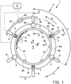
figure 1 shows a front view of a bead-apex station with a bead-apex stitching device according to a first embodiment of the invention; -
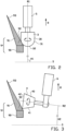
figures 2 and 3 show cross sections of the bead-apex stitching device according to line II-II and line III-III, respectively, infigure 1 ; -
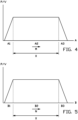
figures 4 and 5 show control schemes for controlling the bead-apex stitching device according tofigure 1 ; -
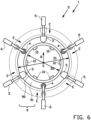
figure 6 shows a front view of the bead-apex station adjusted to a smaller diameter bead-apex compared to the bead-apex infigure 1 ; -
figure 7 shows a side view in cross section of the bead-apex station according tofigure 1 ; and -
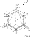
figure 8 shows a front view of an alternative bead-apex station with an alternative bead-apex stitching device according to a second embodiment of the invention. -
Figures 1 ,6 and7 show a bead-apex station 1 according to a first exemplary embodiment of the invention. The bead-apex station 1 may be an individual station, or part of a multi-station tire building machine, such as a turret (not shown), known per se. - The bead-
apex station 1 comprises one or morebead holders 10 for holding a bead core or bead 90 in an annular or ring-shaped configuration about a central axis S. An elastomeric filler or apex is, or has been, applied concentrically around thebead 90. The bead-apex station 1 is configured for pressing or stitching theapex 91 onto thebead 90 to form a so-called bead-apex 9. The bead-apex 9 can be used in subsequent stages of tire building to form a green or unvulcanized tire. In this exemplary embodiment, the bead-apex station 1 comprises abead holder frame 11 for carrying the one ormore bead holders 10 and abead holder drive 12 for driving the one ormore bead holders 10 and/or thebead holder frame 11 in a rotation about the central axis S. - As best seen in
figures 2 and 3 , theapex 91 has a body with a triangular cross section that defines abase 92 and atip 93. Theapex 91 is applied with thebase 92 around thebead 90. - As shown in
figure 1 , the bead-apex station 1 further comprises a bead-apex stitching device 2 for stitching theapex 91 onto thebead 90. The bead-apex stitching device 2 comprises a first set offirst stitching members 3, in particularfirst rollers 3, distributed in a circumferential direction C about the central axis S. Thefirst stitching members 3 may alternatively be formed by another suitable stitching means, such as brushes, pads, fingers, spoons or the like. Eachfirst roller 3 is rotatable about a respective first roller axis R1. In this exemplary embodiment, the first set consists of threefirst rollers 3, although an embodiment with twofirst rollers 3 or more than threefirst rollers 3 is also considered to be within the scope of the present invention. Preferably, thefirst rollers 3 are evenly distributed, i.e. spaced apart equiangularly and/or at a fixed angular interval X. In this particular example, thefirst rollers 3 are spaced apart over an angular interval X of one-hundred-and-twenty degrees. - The bead-
apex station 2 further comprises a second set ofsecond stitching members 4, in particularsecond rollers 4. Thefirst stitching members 3 may alternatively be formed by another suitable stitching means, such as brushes, pads, fingers, spoons or the like. In this example, thesecond stitching members 4 alternate with thefirst rollers 3 of the first set in the circumferential direction C. In other words, considered in the circumferential direction C, the bead-apex station 2 has a first set ofstitching members 3 and a second set ofstitching members 4 distributed in the circumferential direction C in an alternating pattern, i.e. a pattern consecutively comprising a repeating group of one of thefirst stitching members 3 and one of thesecond stitching members 4. Eachsecond roller 4 is rotatable about a respective second roller axis R2. It will be understood that the considerations regarding the amount and distribution of thefirst rollers 3 apply mutatis mutandis to thesecond rollers 4. - The
first rollers 3 and thesecond rollers 4 are designed, configured and/or arranged to press or stitch theapex 91 to thebead 90 in a different manner different. In other words, thefirst rollers 3 have a different purpose or function to thesecond rollers 4. - In this exemplary embodiment, the
first rollers 3 are different in shape to thesecond rollers 4. In particular, as best seen infigure 2 , eachfirst roller 3 comprises aroller body 30 that defines an obtuse circumferential surface or pressingsurface 31. Preferably, the obtuse pressingsurface 31 transitions into a dome-shaped and/or taperingdistal end 32. In contrast, as shown infigure 3 , eachsecond roller 4 comprises aroller body 40 that defines a pointy circumferential surface or pressingsurface 41. In particular, thepressing surface 41 has a sharp or pointy transition to a surface that defines thedistal end 42 of the respectivesecond roller 4. In other words, theroller body 30 of thefirst roller 3 has apressing surface 31 facing the apex 91 with a rounded or 'soft' contour, while theroller body 40 of thesecond roller 4 has apressing surface 41 facing the apex 91 with a relatively sharp, distinct pressing edge. - It is also envisioned that the
first rollers 3 and thesecond rollers 4 may have an identical shape having two sides used for the different purposes. For example, therollers rollers rollers rollers rollers - The
first rollers 3 are held in an orientation in which the respective first roller axes R1 are perpendicular or substantially perpendicular to the central axis S, i.e. within a first orientation range H1 of seventy to one-hundred-and-ten degrees to the central axis S. Thesecond rollers 4 are held in a different orientation in which the respective second roller axes R2 are parallel or almost parallel to the central axis S. Alternatively, the second roller axes R2 may be positioned at a more inclined or oblique angle to the central axis S. 7. In any case, the second roller axes R2 extend within a second orientation range H2 of zero to sixty degrees to the central axis S. The difference in orientation between the roller axes R1, R2 contributes to thefirst rollers 3 and thesecond rollers 4 performing different stitching purposes. - In particular, the
first rollers 3 can roll in the circumferential direction C along a radial or substantially radial plane with respect to the central axis S and exert a pressure force onto the apex 91 in a direction parallel to said central axis S. As such, the first rollers can smooth out irregularities in the apex 91 to provide a smoother and/or more uniform bead-apex 9. In contrast, thesecond rollers 4 can roll in the circumferential direction C along a cylindrical plane about the central axis S and exert a pressure force onto the apex 91 in a direction that is predominantly pointing radially inwards, i.e. towards the central axis S. As such, thesecond rollers 4 can strongly press thebase 92 of the apex 91 onto thebead 90. - As shown in
figure 6 , eachfirst roller 3 of the first set can be moved, driven, actuated and/or positioned with at least a vector component in a radial direction R perpendicular to the central axis S by a respectivefirst actuator 5. Alternatively, eachfirst roller 3 can be driven in a direction parallel to the central axis S. Similarly, eachsecond roller 4 of the second set can be moved, driven, actuated and/or positioned with at least a vector component in the radial direction R by a respectivesecond actuator 6. Thesecond actuator 6 may be positioned at an oblique angle to the central axis S to move the correspondingsecond roller 4 at said oblique angle, i.e. in a range of ten to eighty degrees to said central axis S. Preferably, thefirst rollers 3 of the first set are all moved at the same time and to the same extent, i.e. synchronously or by a single actuator. Similarly, thesecond rollers 4 of the second set are all moved at the same time and to the same extent. The diameter adjustment of the first set and the second set may be independently controlled, i.e. thefirst rollers 3 may be controlled to move to a slightly different diameter than thesecond rollers 4, to press onto the apex 91 at a slightly different radius. Hence, the radial position of therollers bead 90, the apex 91 or the bead-apex 9. Theactuators rollers - The
same actuators rollers roller rollers individual rollers rollers apex stitching device 2 with one or more biasing members (not shown), such as springs. - As shown in
figure 1 , the bead-apex station 1 is configured for generating a relative rotation between thefirst rollers 3 of the first set and the bead-apex 9 in the circumferential direction C about the central axis S. This can be achieved in various ways. In this exemplary embodiment, the first set ofrollers 3 is rotatable as a whole about the central axis S while thebead holder 10 remains stationary. The bead-apex stitching device 2 may comprise a stitching base or astitching frame 21 for supporting or holding thefirst rollers 3 in a fixed mutual relationship and astitching drive 22 that engages with thestitching frame 21 to rotate saidstitching frame 21 in the circumferential direction C. - Alternatively, the one or
more bead holders 10 may be rotated relative to the first set ofrollers 3, or both the one ormore bead holders 10 and the first set ofrollers 3 may be rotated at the same time in opposite directions. The bead-apex station 1 may be provided with a bead holder base orbead holder frame 11 to support or hold the one ormore bead holders 10 and abead holder drive 12 to rotate saidbead holder frame 11 in the circumferential direction C. - Preferably, the second set is rotated together with the first set. In other words, the first set and the second set are rotated in unison. Hence, the relative position between the
first rollers 3 and thesecond rollers 4 in the circumferential direction C can remain the same during the rotation about the central axis S. - The bead-
apex station 1 may optionally comprises a third set or further sets of stitching members (not shown) to perform other functions. The third set of stitching members may for example be positioned to press or stitch a transition area between thebead 90 and the apex 91, i.e. the area at thebase 92 of the apex 91 and the directly adjacent area of thebead 90. - The bead-
apex station 1 or the bead-apex stitching device 2 is further provided with acontrol unit 8 that is electronically or operationally connected to thebead holder drive 12, thestitching drive 22, the one or morefirst actuators 5 and/or the one or moresecond actuators 6 to control the various operations of the bead-apex station 1 and/or the bead-apex stitching device 2. - In this exemplary embodiment, the
control unit 8 is programmed, loaded with instructions, adapted, arranged or configured for controlling thestitching drive 22 to rotate the first set in a first rotation direction M and to subsequently rotate the first set in a second rotation direction N, opposite to the first rotation direction M. In this example, the first set is preferably rotated over a first rotation range A of less than one revolution, i.e. less than three-hundred-and-sixty degrees, and over a second rotation range B of less than one revolution, i.e. less than three-hundred-and-sixty degrees. The first set may however also be rotated in opposite directions over one revolution or more than one revolution. The second set is rotated together or in unison with the first set. As mentioned before, thecontrol unit 8 may alternatively be configured to rotate thebead holder 10 relative to the first set by controlling thebead holder drive 12. - During the rotation in the first rotation direction M, the
first rollers 3 of the first set are controlled to press or stitch the apex 91 to thebead 90. During this stage of stitching, thesecond rollers 4 of the second set may be retracted in a retraction direction L, as shown infigure 7 , so as not to interfere with thefirst rollers 3 of the first set. During or shortly prior to the opposite rotation in the second rotation direction N, thesecond rollers 4 of the second set are brought into contact with the apex 91 and thefirst rollers 3 of the first set may be retracted in the retraction direction L to allow for the subsequent stage of stitching. Hence, the stitching process can be split up in two distinct stages. - The retraction direction L of the
first rollers 3 and thesecond rollers 4 is shown to be parallel or substantially parallel to the central axis S. Alternatively, the retraction direction L may be in the working direction of therespective actuators actuators respective rollers - By rotating the
rollers apex stitching device 2 can be reduced considerably. Moreover, it can be prevented that control lines, such as electric cables and pneumatic tubes, get entangled. - It is submitted however that if the combined stroke of the first set and the second set is small enough, i.e. if each set has a sufficient amount of the rollers to reduce the angular interval X, both stitching stages may also be performed in the same rotation direction, i.e. following upon each other without reversing the rotation direction.
-
Figures 4 and 5 show control schemes of the first set being rotated in the first rotation direction M and the second set being rotated in the second rotation direction N, respectively. The horizontal axes represent the angular position of the first set and the second set along a first rotation range A and a second rotation range B, respectively. The vertical axes represent one or more parameters of first set and the second set, respectively, i.e. the angular velocity V of the respective set in the circumferential direction C or the pressure P exerted by the respective set onto the apex 91. In this exemplary embodiment, the rotation ranges A, B are larger than one time the angular interval X between thefirst rollers 3. Preferably, the rotation ranges A, B are smaller the two times said angular interval X. Alternatively, the rotation ranges A, B may be larger than two times said angular interval X to make sure that each area of the apex 91 is pressed by at least two rollers of the respective set. The excess range can be used to start up and slow down the sets. In particular, both ranges A, B comprise a plurality of subranges, more specifically a start subrange A1, B1, a middle subrange A2, B2 and an end subrange A3, B3. Thecontrol unit 8 is configured for keeping the one or more parameters P, V constant or substantially constant in the middle subrange A2 and for increasing and decreasing the one or more parameters P, V in the start subrange A1 and the end subrange A3, respectively. - As mentioned before, the same control schemes may be used to control the rotation of the
bead holder 10 instead of or in addition to the rotation of the sets ofrollers -
Figure 7 shows an alternative bead-apex station 101 with an alternative bead-apex stitching device 102 that differs from the aforementioned bead-apex stitching device 2 in that eachfirst roller 3 of the first set is positionable at or tiltable towards a tilt angle K about a tilt axis T perpendicular to the first roller axis R1 and/or parallel to the central axis S into a tilted orientation in which the first roller axis R1 does not intersect with the central axis S. In the tilted orientation, the rolling direction of thefirst rollers 3 can be slightly misaligned with respect to the circumferential direction C, thereby causing thefirst rollers 3 to exert a sideward force, i.e. a friction force, onto the apex 91 that can effectively smooth out irregularities in saidapex 91. Thefirst rollers 3 may be actively tilted into said tilted orientation, or they may be installed in said tilted orientation. The tilt angle K preferably remains constant. Alternatively, it may be actively controlled and/or varied during stitching. - A method for stitching the apex 91 to the
bead 90 using the aforementioned bead-apex station apex stitching device figures 1-8 . - As shown in
figure 1 , the method comprises the steps of: - a) first stitching the apex 91 to the
bead 90 using thefirst rollers 3 of the first set; and - b) subsequently stitching the apex 91 to the
bead 90 using thesecond rollers 4 of the second set. - During step the first set is rotated in the first rotation direction M about the central axis S according to the control scheme in
figure 4 . During step b) the first set is rotated in the second rotation direction N according to the control scheme infigure 5 . The second set is rotated together with the first set. During the control scheme infigure 4 , the first set is active in the sense that thefirst rollers 3 are pressed onto the apex 91. During the control scheme offigure 5 , the second set is active in the sense that thesecond rollers 4 are pressed onto the apex 91. The set that is inactive can be retracted in the retraction direction L, as shown infigure 7 . - It is noted that the stages of the stitching may partially overlap, i.e. one set may already be brought into position before the other set is retracted in the retraction direction L. The latter may save cycle time and/or it may be beneficial to have the two sets contacting the apex 91 simultaneously at least once during the cycle.
- The bead-
apex station rollers bead 90 and/or the apex 91. - As mentioned before, the
bead holder 10 may be rotated instead of or in addition to the rotation of the first set. In that case, the method comprises the steps of: - a) first stitching the apex 91 to the
bead 90 using thefirst rollers 3 of the first set while rotating thebead holder 10 in the first rotation direction M; and - b) subsequently stitching the apex 91 to the
bead 90 using thesecond rollers 4 of the second set while rotating thebead holder 10 in the second rotation direction N. - It is further noted that the
control unit 8 may control the various operational parameters of the bead-apex station apex stitching device bead 90 and/or the apex 91, and/or based on the tire design, i.e. the construction, shape and/or dimensions of the various tire components and their relative position in the green tire to be formed. - It is to be understood that the above description is included to illustrate the operation of the preferred embodiments and is not meant to limit the scope of the invention. From the above discussion, many variations will be apparent to one skilled in the art that would yet be encompassed by the scope of the present invention.
-
- 1
- bead-apex station
- 10
- bead holder
- 11
- bead holder frame
- 12
- bead holder drive
- 2
- bead-apex stitching device
- 21
- stitching frame
- 22
- stitching drive
- 3
- first stitching member
- 30
- roller body
- 31
- pressing surface
- 32
- distal end
- 4
- second stitching member
- 40
- roller body
- 41
- pressing surface
- 42
- distal end
- 5
- first actuator
- 6
- second actuator
- 8
- control unit
- 9
- bead-apex
- 90
- bead
- 91
- apex
- 92
- base
- 93
- tip
- 101
- alternative bead-apex station
- 102
- alternative bead-apex stitching device
- A
- first rotation range
- A1
- start subrange
- A2
- middle subrange
- A3
- end subrange
- B
- second rotation range
- B1
- start subrange
- B2
- middle subrange
- B3
- end subrange
- C
- circumferential direction
- D1
- first diameter
- D2
- second diameter
- E
- extension direction
- H1
- first orientation range
- H2
- second orientation range
- K
- tilt angle
- L
- retraction direction
- M
- first rotation direction
- N
- second rotation direction
- P
- pressure
- R
- radial direction
- R1
- first roller axis
- R2
- second roller axis
- S
- central axis
- T
- tilt axis
- V
- angular velocity
- X
- angular interval
Claims (12)
- Bead-apex stitching device for stitching an apex to a bead, wherein the bead-apex stitching device comprises at least one first stitching member for stitching the apex to the bead and at least one second stitching member for stitching the apex to the bead in a manner different from the first stitching member, wherein the at least one first stitching member and the at least one second stitching member together are rotatable in a circumferential direction about a central axis, wherein the bead-apex stitching device comprises a stitching drive for driving the rotation of the at least one first stitching member and the at least one second stitching member about the central axis and a control unit that is operationally connected to the stitching drive, wherein the control unit is configured for controlling the stitching drive to rotate the at least one first stitching member and the at least one second stitching member in a first rotation direction and to subsequently rotate the at least one first stitching member and the at least one second stitching member in a second rotation direction, opposite to the first rotation direction.
- Bead-apex stitching device according to claim 1, wherein the first rotation range is less than one revolution.
- Bead-apex stitching device according to claim 1 or 2, wherein the second rotation range is less than one revolution.
- Bead-apex station comprising a bead-apex stitching device for stitching an apex to a bead, wherein the bead-apex stitching device comprises at least one first stitching member for stitching the apex to the bead and at least one second stitching member for stitching the apex to the bead in a manner different from the first stitching member, and a bead holder for holding the bead concentrically to the bead-apex stitching device, wherein the bead holder is rotatable in the circumferential direction about the central axis, wherein the bead-apex station comprises a bead holder drive for driving the rotation of the bead holder and a control unit that is operationally connected to the bead holder drive, wherein the control unit is configured for controlling the bead holder drive to rotate the bead holder in a first rotation direction over a first rotation range and to subsequently rotate the bead holder in a second rotation direction, opposite to the first rotation direction, over a second rotation range.
- Bead-apex station according to claim 4, wherein the first rotation range is less than one revolution.
- Bead-apex station according to claim 4 or 5, wherein the second rotation range is less than one revolution.
- Method for stitching an apex to a bead using the bead-apex stitching device according to any one of claims 1-3, wherein the method comprises the steps of:a) first stitching the apex to the bead using the at least one first stitching member by rotating the at least one first stitching member and the at least one second stitching member in the first rotation direction; andb) subsequently stitching the apex to the bead using the at least one second stitching member by rotating the at least one first stitching member and the at least one second stitching member in the second rotation direction.
- Method according to claim 7, wherein the first rotation range is less than one revolution.
- Method according to claim 7 or 8, wherein the second rotation range is less than one revolution.
- Method for stitching an apex to a bead using the bead-apex station according to any one of claims 4-6, wherein the method comprises the steps of:a) first stitching the apex to the bead using the at least one first stitching member while rotating the bead holder in the first rotation direction over the first rotation range; andb) subsequently stitching the apex to the bead using the at least one second stitching member while rotating the bead holder in the second rotation direction, opposite to the first rotation direction, over the second rotation range.
- Method according to claim 10, wherein the first rotation range is less than one revolution.
- Method according to claim 10 or 11, wherein the second rotation range is less than one revolution.
Applications Claiming Priority (4)
| Application Number | Priority Date | Filing Date | Title |
|---|---|---|---|
| NL2027903 | 2021-04-01 | ||
| NL2028663A NL2028663B1 (en) | 2021-04-01 | 2021-07-08 | Bead-apex stitching device, bead-apex station and method for stitching an apex to a bead |
| PCT/NL2022/050144 WO2022211615A1 (en) | 2021-04-01 | 2022-03-17 | Bead-apex stitching device and method for stitching an apex to a bead |
| EP22711688.6A EP4313573B1 (en) | 2021-04-01 | 2022-03-17 | Bead-apex stitching device and method for stitching an apex to a bead |
Related Parent Applications (1)
| Application Number | Title | Priority Date | Filing Date |
|---|---|---|---|
| EP22711688.6A Division EP4313573B1 (en) | 2021-04-01 | 2022-03-17 | Bead-apex stitching device and method for stitching an apex to a bead |
Publications (3)
| Publication Number | Publication Date |
|---|---|
| EP4552833A1 true EP4552833A1 (en) | 2025-05-14 |
| EP4552833B1 EP4552833B1 (en) | 2026-03-11 |
| EP4552833C0 EP4552833C0 (en) | 2026-03-11 |
Family
ID=80820209
Family Applications (2)
| Application Number | Title | Priority Date | Filing Date |
|---|---|---|---|
| EP22711688.6A Active EP4313573B1 (en) | 2021-04-01 | 2022-03-17 | Bead-apex stitching device and method for stitching an apex to a bead |
| EP25151291.9A Active EP4552833B1 (en) | 2021-04-01 | 2022-03-17 | Bead-apex stitching device, bead-apex station and method for stitching an apex to a bead |
Family Applications Before (1)
| Application Number | Title | Priority Date | Filing Date |
|---|---|---|---|
| EP22711688.6A Active EP4313573B1 (en) | 2021-04-01 | 2022-03-17 | Bead-apex stitching device and method for stitching an apex to a bead |
Country Status (15)
| Country | Link |
|---|---|
| US (1) | US12122112B2 (en) |
| EP (2) | EP4313573B1 (en) |
| JP (1) | JP7379721B2 (en) |
| KR (1) | KR102670797B1 (en) |
| CN (3) | CN119974623A (en) |
| BR (1) | BR112023019538A2 (en) |
| CA (1) | CA3213196A1 (en) |
| ES (1) | ES3013591T3 (en) |
| HU (1) | HUE071249T2 (en) |
| MA (1) | MA63932B1 (en) |
| MX (1) | MX2023011490A (en) |
| PL (1) | PL4313573T3 (en) |
| RS (1) | RS66728B1 (en) |
| TW (1) | TW202304694A (en) |
| WO (1) | WO2022211615A1 (en) |
Families Citing this family (1)
| Publication number | Priority date | Publication date | Assignee | Title |
|---|---|---|---|---|
| BR112023019538A2 (en) * | 2021-04-01 | 2023-10-31 | Vmi Holland Bv | BEAD APEX SEWING DEVICE, BEAD APEX STATION AND METHOD FOR SEWING AN APEX TO A BEAD |
Citations (7)
| Publication number | Priority date | Publication date | Assignee | Title |
|---|---|---|---|---|
| GB126111A (en) * | 1918-04-25 | 1919-04-25 | Dunlop Rubber Co | Improvements in or relating to Machines for Making Pneumatic Tyre Covers or Casings. |
| DE1129684B (en) * | 1958-11-29 | 1962-05-17 | Dunlop Rubber Co | Device for rolling tire building parts onto the face of tire building drums |
| EP0345633A2 (en) * | 1988-06-08 | 1989-12-13 | PIRELLI COORDINAMENTO PNEUMATICI S.p.A. | Device for applying an elastomeric filler on the bead core of a pneumatic tire |
| US5203938A (en) * | 1991-01-31 | 1993-04-20 | Heico Aluminum Products, Inc. | Method and apparatus for forming an apex filler and/or applying an apex filler to a bead ring sub-assembly |
| JPH11227068A (en) * | 1998-02-18 | 1999-08-24 | Sumitomo Rubber Ind Ltd | Stitcher equipment |
| EP1755874B1 (en) | 2004-06-04 | 2008-05-21 | Vmi Epe Holland B.V. | Formation of a tire bead assembly |
| CN109483925A (en) * | 2018-11-27 | 2019-03-19 | 软控股份有限公司 | Combined press roller arrangement and tire rolling depression method |
Family Cites Families (20)
| Publication number | Priority date | Publication date | Assignee | Title |
|---|---|---|---|---|
| US1468717A (en) * | 1921-06-18 | 1923-09-25 | Kienle David | Window seat |
| JPS4826870B1 (en) | 1967-07-05 | 1973-08-16 | ||
| JPS522432B2 (en) * | 1971-08-12 | 1977-01-21 | ||
| JPS5129551B2 (en) * | 1972-04-05 | 1976-08-26 | ||
| JPS5237515B2 (en) * | 1974-09-26 | 1977-09-22 | ||
| GB1468717A (en) * | 1974-11-25 | 1977-03-30 | Bridgestone Tire Co Ltd | Apparatus for and method of applying a strip of elastic material to a tyre bead |
| WO1991012127A1 (en) | 1990-02-15 | 1991-08-22 | Sumitomo Rubber Industries, Ltd. | Method of sticking bead apexes and apparatus therefor |
| US5100497A (en) * | 1991-01-31 | 1992-03-31 | Steelastic West, Inc. | Method and apparatus for forming an apex filler and/or applying an apex filler to a bead ring sub-assembly |
| JPH08142227A (en) * | 1994-11-22 | 1996-06-04 | Bridgestone Corp | Method and apparatus for bonding filler |
| JP3251180B2 (en) * | 1996-10-11 | 2002-01-28 | 富士通株式会社 | Heat dissipation structure of notebook computer |
| JP3338663B2 (en) | 1999-06-16 | 2002-10-28 | 住友ゴム工業株式会社 | Single wire bead manufacturing equipment |
| AU6946900A (en) * | 1999-09-03 | 2001-04-10 | Bartell Machinery Systems, Llc | Apparatus for stitching and seaming elastomeric fillers to tire beads |
| US6769468B2 (en) * | 2001-09-21 | 2004-08-03 | The Goodyear Tire & Rubber Company | Tire building drum having expandable center section and independently expandable bead lock assemblies in the end sections |
| JP4826870B2 (en) | 2003-12-02 | 2011-11-30 | ソニー株式会社 | Pixel circuit, driving method thereof, active matrix device, and display device |
| US8585845B2 (en) * | 2010-11-10 | 2013-11-19 | The Goodyear Tire & Rubber Company | Tire-forming apparatus and related methods |
| NL2009373C2 (en) | 2012-08-28 | 2014-03-03 | Vmi Holland Bv | Device for providing a bead. |
| NL2009946C2 (en) * | 2012-12-10 | 2014-06-11 | Vmi Holland Bv | Tyre building machine for forming a bead-apex assembly. |
| JP6501671B2 (en) | 2015-08-19 | 2019-04-17 | 住友ゴム工業株式会社 | Method and apparatus for crimping bead member |
| JP7148368B2 (en) | 2018-11-15 | 2022-10-05 | Toyo Tire株式会社 | Bead core manufacturing equipment |
| BR112023019538A2 (en) | 2021-04-01 | 2023-10-31 | Vmi Holland Bv | BEAD APEX SEWING DEVICE, BEAD APEX STATION AND METHOD FOR SEWING AN APEX TO A BEAD |
-
2022
- 2022-03-17 BR BR112023019538A patent/BR112023019538A2/en unknown
- 2022-03-17 EP EP22711688.6A patent/EP4313573B1/en active Active
- 2022-03-17 JP JP2022546460A patent/JP7379721B2/en active Active
- 2022-03-17 PL PL22711688.6T patent/PL4313573T3/en unknown
- 2022-03-17 MA MA63932A patent/MA63932B1/en unknown
- 2022-03-17 WO PCT/NL2022/050144 patent/WO2022211615A1/en not_active Ceased
- 2022-03-17 MX MX2023011490A patent/MX2023011490A/en unknown
- 2022-03-17 CA CA3213196A patent/CA3213196A1/en active Pending
- 2022-03-17 HU HUE22711688A patent/HUE071249T2/en unknown
- 2022-03-17 KR KR1020237037044A patent/KR102670797B1/en active Active
- 2022-03-17 ES ES22711688T patent/ES3013591T3/en active Active
- 2022-03-17 US US18/285,355 patent/US12122112B2/en active Active
- 2022-03-17 EP EP25151291.9A patent/EP4552833B1/en active Active
- 2022-03-17 RS RS20250388A patent/RS66728B1/en unknown
- 2022-03-18 TW TW111110146A patent/TW202304694A/en unknown
- 2022-04-01 CN CN202510296835.4A patent/CN119974623A/en active Pending
- 2022-04-01 CN CN202220814367.7U patent/CN218342890U/en not_active Withdrawn - After Issue
- 2022-04-01 CN CN202210348407.8A patent/CN115195175B/en active Active
Patent Citations (7)
| Publication number | Priority date | Publication date | Assignee | Title |
|---|---|---|---|---|
| GB126111A (en) * | 1918-04-25 | 1919-04-25 | Dunlop Rubber Co | Improvements in or relating to Machines for Making Pneumatic Tyre Covers or Casings. |
| DE1129684B (en) * | 1958-11-29 | 1962-05-17 | Dunlop Rubber Co | Device for rolling tire building parts onto the face of tire building drums |
| EP0345633A2 (en) * | 1988-06-08 | 1989-12-13 | PIRELLI COORDINAMENTO PNEUMATICI S.p.A. | Device for applying an elastomeric filler on the bead core of a pneumatic tire |
| US5203938A (en) * | 1991-01-31 | 1993-04-20 | Heico Aluminum Products, Inc. | Method and apparatus for forming an apex filler and/or applying an apex filler to a bead ring sub-assembly |
| JPH11227068A (en) * | 1998-02-18 | 1999-08-24 | Sumitomo Rubber Ind Ltd | Stitcher equipment |
| EP1755874B1 (en) | 2004-06-04 | 2008-05-21 | Vmi Epe Holland B.V. | Formation of a tire bead assembly |
| CN109483925A (en) * | 2018-11-27 | 2019-03-19 | 软控股份有限公司 | Combined press roller arrangement and tire rolling depression method |
Also Published As
| Publication number | Publication date |
|---|---|
| KR20230154096A (en) | 2023-11-07 |
| EP4552833B1 (en) | 2026-03-11 |
| CA3213196A1 (en) | 2022-10-06 |
| CN119974623A (en) | 2025-05-13 |
| CN115195175B (en) | 2025-04-11 |
| KR102670797B1 (en) | 2024-05-29 |
| EP4313573B1 (en) | 2025-02-12 |
| BR112023019538A2 (en) | 2023-10-31 |
| US12122112B2 (en) | 2024-10-22 |
| EP4313573A1 (en) | 2024-02-07 |
| PL4313573T3 (en) | 2025-06-02 |
| CN218342890U (en) | 2023-01-20 |
| JP7379721B2 (en) | 2023-11-14 |
| US20240190094A1 (en) | 2024-06-13 |
| EP4313573C0 (en) | 2025-02-12 |
| ES3013591T3 (en) | 2025-04-14 |
| MX2023011490A (en) | 2023-10-04 |
| EP4552833C0 (en) | 2026-03-11 |
| HUE071249T2 (en) | 2025-08-28 |
| JP2023523380A (en) | 2023-06-05 |
| CN115195175A (en) | 2022-10-18 |
| RS66728B1 (en) | 2025-05-30 |
| MA63932B1 (en) | 2025-02-28 |
| TW202304694A (en) | 2023-02-01 |
| WO2022211615A1 (en) | 2022-10-06 |
Similar Documents
| Publication | Publication Date | Title |
|---|---|---|
| KR100973178B1 (en) | How to make products of various diameters and molding machines | |
| JP2957154B2 (en) | Pipe end forming method and apparatus | |
| EP1017515A1 (en) | Spinning processing method and apparatus therefor | |
| JP2001259749A (en) | Forming method of tube | |
| JP3382048B2 (en) | Clamping device for pipe roundness correction | |
| EP4552833B1 (en) | Bead-apex stitching device, bead-apex station and method for stitching an apex to a bead | |
| JP2957153B2 (en) | Pipe end forming method and apparatus | |
| JP4086394B2 (en) | End material forming method and apparatus for tube material | |
| US20140135973A1 (en) | Forming and/or Cutting Plate Workpieces | |
| JP2024541504A (en) | Method for mounting a pneumatic tire on a wheel rim | |
| US20040050130A1 (en) | Method and forming machine for deforming a hollow workpiece | |
| CN112124888B (en) | Transfer system, conveying system and method for removing and pushing up sleeve-shaped workpieces | |
| US20250001715A1 (en) | Bead-apex stitching device, bead-apex station and method for stitching an apex to a bead | |
| NL2028663B1 (en) | Bead-apex stitching device, bead-apex station and method for stitching an apex to a bead | |
| EP1485217B1 (en) | Method and forming machine for working a workpiece | |
| US7140219B2 (en) | Swaging head assembly | |
| JPH0615146B2 (en) | Method and apparatus for making a ruled surface of a cam | |
| US5676007A (en) | Flow-forming-machine | |
| JPS5814067Y2 (en) | Copying shift device | |
| JP2013081984A (en) | Apparatus for manufacturing unequal thickness rim | |
| JP2568200Y2 (en) | Cam device | |
| CN119456763A (en) | A special-shaped curling method and a special-shaped curling device | |
| JP2024544996A (en) | Method for automatically feeding a workpiece to a gear cutting machine |
Legal Events
| Date | Code | Title | Description |
|---|---|---|---|
| PUAI | Public reference made under article 153(3) epc to a published international application that has entered the european phase |
Free format text: ORIGINAL CODE: 0009012 |
|
| STAA | Information on the status of an ep patent application or granted ep patent |
Free format text: STATUS: THE APPLICATION HAS BEEN PUBLISHED |
|
| AC | Divisional application: reference to earlier application |
Ref document number: 4313573 Country of ref document: EP Kind code of ref document: P |
|
| AK | Designated contracting states |
Kind code of ref document: A1 Designated state(s): AL AT BE BG CH CY CZ DE DK EE ES FI FR GB GR HR HU IE IS IT LI LT LU LV MC MK MT NL NO PL PT RO RS SE SI SK SM TR |
|
| STAA | Information on the status of an ep patent application or granted ep patent |
Free format text: STATUS: REQUEST FOR EXAMINATION WAS MADE |
|
| 17P | Request for examination filed |
Effective date: 20250611 |
|
| GRAP | Despatch of communication of intention to grant a patent |
Free format text: ORIGINAL CODE: EPIDOSNIGR1 |
|
| STAA | Information on the status of an ep patent application or granted ep patent |
Free format text: STATUS: GRANT OF PATENT IS INTENDED |
|
| INTG | Intention to grant announced |
Effective date: 20251007 |
|
| GRAS | Grant fee paid |
Free format text: ORIGINAL CODE: EPIDOSNIGR3 |
|
| GRAA | (expected) grant |
Free format text: ORIGINAL CODE: 0009210 |
|
| STAA | Information on the status of an ep patent application or granted ep patent |
Free format text: STATUS: THE PATENT HAS BEEN GRANTED |
|
| AC | Divisional application: reference to earlier application |
Ref document number: 4313573 Country of ref document: EP Kind code of ref document: P |
|
| AK | Designated contracting states |
Kind code of ref document: B1 Designated state(s): AL AT BE BG CH CY CZ DE DK EE ES FI FR GB GR HR HU IE IS IT LI LT LU LV MC MK MT NL NO PL PT RO RS SE SI SK SM TR |
|
| REG | Reference to a national code |
Ref country code: CH Ref legal event code: F10 Free format text: ST27 STATUS EVENT CODE: U-0-0-F10-F00 (AS PROVIDED BY THE NATIONAL OFFICE) Effective date: 20260311 Ref country code: GB Ref legal event code: FG4D |
|
| REG | Reference to a national code |
Ref country code: DE Ref legal event code: R096 Ref document number: 602022032380 Country of ref document: DE |
|
| REG | Reference to a national code |
Ref country code: IE Ref legal event code: FG4D |
|
| PGFP | Annual fee paid to national office [announced via postgrant information from national office to epo] |
Ref country code: AT Payment date: 20260312 Year of fee payment: 5 |
|
| U01 | Request for unitary effect filed |
Effective date: 20260312 |
|
| U07 | Unitary effect registered |
Designated state(s): AT BE BG DE DK EE FI FR IT LT LU LV MT NL PT RO SE SI Effective date: 20260319 |
|
| U20 | Renewal fee for the european patent with unitary effect paid |
Year of fee payment: 5 Effective date: 20260331 |