EP4550472A2 - Kathodenmischung, festkörpersekundärbatterie damit und verfahren zur herstellung der festkörpersekundärbatterie - Google Patents
Kathodenmischung, festkörpersekundärbatterie damit und verfahren zur herstellung der festkörpersekundärbatterie Download PDFInfo
- Publication number
- EP4550472A2 EP4550472A2 EP24205727.1A EP24205727A EP4550472A2 EP 4550472 A2 EP4550472 A2 EP 4550472A2 EP 24205727 A EP24205727 A EP 24205727A EP 4550472 A2 EP4550472 A2 EP 4550472A2
- Authority
- EP
- European Patent Office
- Prior art keywords
- carbon
- composite
- active material
- cathode
- solid
- Prior art date
- Legal status (The legal status is an assumption and is not a legal conclusion. Google has not performed a legal analysis and makes no representation as to the accuracy of the status listed.)
- Pending
Links
Images


Classifications
-
- H—ELECTRICITY
- H01—ELECTRIC ELEMENTS
- H01M—PROCESSES OR MEANS, e.g. BATTERIES, FOR THE DIRECT CONVERSION OF CHEMICAL ENERGY INTO ELECTRICAL ENERGY
- H01M4/00—Electrodes
- H01M4/02—Electrodes composed of, or comprising, active material
- H01M4/13—Electrodes for accumulators with non-aqueous electrolyte, e.g. for lithium-accumulators; Processes of manufacture thereof
- H01M4/136—Electrodes based on inorganic compounds other than oxides or hydroxides, e.g. sulfides, selenides, tellurides, halogenides or LiCoFy
-
- H—ELECTRICITY
- H01—ELECTRIC ELEMENTS
- H01M—PROCESSES OR MEANS, e.g. BATTERIES, FOR THE DIRECT CONVERSION OF CHEMICAL ENERGY INTO ELECTRICAL ENERGY
- H01M4/00—Electrodes
- H01M4/02—Electrodes composed of, or comprising, active material
- H01M4/36—Selection of substances as active materials, active masses, active liquids
- H01M4/362—Composites
- H01M4/364—Composites as mixtures
-
- H—ELECTRICITY
- H01—ELECTRIC ELEMENTS
- H01M—PROCESSES OR MEANS, e.g. BATTERIES, FOR THE DIRECT CONVERSION OF CHEMICAL ENERGY INTO ELECTRICAL ENERGY
- H01M10/00—Secondary cells; Manufacture thereof
- H01M10/05—Accumulators with non-aqueous electrolyte
- H01M10/052—Li-accumulators
-
- H—ELECTRICITY
- H01—ELECTRIC ELEMENTS
- H01M—PROCESSES OR MEANS, e.g. BATTERIES, FOR THE DIRECT CONVERSION OF CHEMICAL ENERGY INTO ELECTRICAL ENERGY
- H01M10/00—Secondary cells; Manufacture thereof
- H01M10/05—Accumulators with non-aqueous electrolyte
- H01M10/052—Li-accumulators
- H01M10/0525—Rocking-chair batteries, i.e. batteries with lithium insertion or intercalation in both electrodes; Lithium-ion batteries
-
- H—ELECTRICITY
- H01—ELECTRIC ELEMENTS
- H01M—PROCESSES OR MEANS, e.g. BATTERIES, FOR THE DIRECT CONVERSION OF CHEMICAL ENERGY INTO ELECTRICAL ENERGY
- H01M10/00—Secondary cells; Manufacture thereof
- H01M10/05—Accumulators with non-aqueous electrolyte
- H01M10/056—Accumulators with non-aqueous electrolyte characterised by the materials used as electrolytes, e.g. mixed inorganic/organic electrolytes
- H01M10/0561—Accumulators with non-aqueous electrolyte characterised by the materials used as electrolytes, e.g. mixed inorganic/organic electrolytes the electrolyte being constituted of inorganic materials only
- H01M10/0562—Solid materials
-
- H—ELECTRICITY
- H01—ELECTRIC ELEMENTS
- H01M—PROCESSES OR MEANS, e.g. BATTERIES, FOR THE DIRECT CONVERSION OF CHEMICAL ENERGY INTO ELECTRICAL ENERGY
- H01M10/00—Secondary cells; Manufacture thereof
- H01M10/05—Accumulators with non-aqueous electrolyte
- H01M10/058—Construction or manufacture
- H01M10/0585—Construction or manufacture of accumulators having only flat construction elements, i.e. flat positive electrodes, flat negative electrodes and flat separators
-
- H—ELECTRICITY
- H01—ELECTRIC ELEMENTS
- H01M—PROCESSES OR MEANS, e.g. BATTERIES, FOR THE DIRECT CONVERSION OF CHEMICAL ENERGY INTO ELECTRICAL ENERGY
- H01M4/00—Electrodes
- H01M4/02—Electrodes composed of, or comprising, active material
- H01M4/13—Electrodes for accumulators with non-aqueous electrolyte, e.g. for lithium-accumulators; Processes of manufacture thereof
- H01M4/131—Electrodes based on mixed oxides or hydroxides, or on mixtures of oxides or hydroxides, e.g. LiCoOx
-
- H—ELECTRICITY
- H01—ELECTRIC ELEMENTS
- H01M—PROCESSES OR MEANS, e.g. BATTERIES, FOR THE DIRECT CONVERSION OF CHEMICAL ENERGY INTO ELECTRICAL ENERGY
- H01M4/00—Electrodes
- H01M4/02—Electrodes composed of, or comprising, active material
- H01M4/13—Electrodes for accumulators with non-aqueous electrolyte, e.g. for lithium-accumulators; Processes of manufacture thereof
- H01M4/134—Electrodes based on metals, Si or alloys
-
- H—ELECTRICITY
- H01—ELECTRIC ELEMENTS
- H01M—PROCESSES OR MEANS, e.g. BATTERIES, FOR THE DIRECT CONVERSION OF CHEMICAL ENERGY INTO ELECTRICAL ENERGY
- H01M4/00—Electrodes
- H01M4/02—Electrodes composed of, or comprising, active material
- H01M4/13—Electrodes for accumulators with non-aqueous electrolyte, e.g. for lithium-accumulators; Processes of manufacture thereof
- H01M4/139—Processes of manufacture
- H01M4/1397—Processes of manufacture of electrodes based on inorganic compounds other than oxides or hydroxides, e.g. sulfides, selenides, tellurides, halogenides or LiCoFy
-
- H—ELECTRICITY
- H01—ELECTRIC ELEMENTS
- H01M—PROCESSES OR MEANS, e.g. BATTERIES, FOR THE DIRECT CONVERSION OF CHEMICAL ENERGY INTO ELECTRICAL ENERGY
- H01M4/00—Electrodes
- H01M4/02—Electrodes composed of, or comprising, active material
- H01M4/36—Selection of substances as active materials, active masses, active liquids
- H01M4/362—Composites
- H01M4/366—Composites as layered products
-
- H—ELECTRICITY
- H01—ELECTRIC ELEMENTS
- H01M—PROCESSES OR MEANS, e.g. BATTERIES, FOR THE DIRECT CONVERSION OF CHEMICAL ENERGY INTO ELECTRICAL ENERGY
- H01M4/00—Electrodes
- H01M4/02—Electrodes composed of, or comprising, active material
- H01M4/36—Selection of substances as active materials, active masses, active liquids
- H01M4/38—Selection of substances as active materials, active masses, active liquids of elements or alloys
- H01M4/381—Alkaline or alkaline earth metals elements
- H01M4/382—Lithium
-
- H—ELECTRICITY
- H01—ELECTRIC ELEMENTS
- H01M—PROCESSES OR MEANS, e.g. BATTERIES, FOR THE DIRECT CONVERSION OF CHEMICAL ENERGY INTO ELECTRICAL ENERGY
- H01M4/00—Electrodes
- H01M4/02—Electrodes composed of, or comprising, active material
- H01M4/36—Selection of substances as active materials, active masses, active liquids
- H01M4/48—Selection of substances as active materials, active masses, active liquids of inorganic oxides or hydroxides
- H01M4/52—Selection of substances as active materials, active masses, active liquids of inorganic oxides or hydroxides of nickel, cobalt or iron
- H01M4/525—Selection of substances as active materials, active masses, active liquids of inorganic oxides or hydroxides of nickel, cobalt or iron of mixed oxides or hydroxides containing iron, cobalt or nickel for inserting or intercalating light metals, e.g. LiNiO2, LiCoO2 or LiCoOxFy
-
- H—ELECTRICITY
- H01—ELECTRIC ELEMENTS
- H01M—PROCESSES OR MEANS, e.g. BATTERIES, FOR THE DIRECT CONVERSION OF CHEMICAL ENERGY INTO ELECTRICAL ENERGY
- H01M4/00—Electrodes
- H01M4/02—Electrodes composed of, or comprising, active material
- H01M4/36—Selection of substances as active materials, active masses, active liquids
- H01M4/58—Selection of substances as active materials, active masses, active liquids of inorganic compounds other than oxides or hydroxides, e.g. sulfides, selenides, tellurides, halogenides or LiCoFy; of polyanionic structures, e.g. phosphates, silicates or borates
- H01M4/581—Chalcogenides or intercalation compounds thereof
- H01M4/5815—Sulfides
-
- H—ELECTRICITY
- H01—ELECTRIC ELEMENTS
- H01M—PROCESSES OR MEANS, e.g. BATTERIES, FOR THE DIRECT CONVERSION OF CHEMICAL ENERGY INTO ELECTRICAL ENERGY
- H01M4/00—Electrodes
- H01M4/02—Electrodes composed of, or comprising, active material
- H01M4/36—Selection of substances as active materials, active masses, active liquids
- H01M4/58—Selection of substances as active materials, active masses, active liquids of inorganic compounds other than oxides or hydroxides, e.g. sulfides, selenides, tellurides, halogenides or LiCoFy; of polyanionic structures, e.g. phosphates, silicates or borates
- H01M4/583—Carbonaceous material, e.g. graphite-intercalation compounds or CFx
-
- H—ELECTRICITY
- H01—ELECTRIC ELEMENTS
- H01M—PROCESSES OR MEANS, e.g. BATTERIES, FOR THE DIRECT CONVERSION OF CHEMICAL ENERGY INTO ELECTRICAL ENERGY
- H01M4/00—Electrodes
- H01M4/02—Electrodes composed of, or comprising, active material
- H01M4/62—Selection of inactive substances as ingredients for active masses, e.g. binders, fillers
- H01M4/624—Electric conductive fillers
- H01M4/625—Carbon or graphite
-
- H—ELECTRICITY
- H01—ELECTRIC ELEMENTS
- H01M—PROCESSES OR MEANS, e.g. BATTERIES, FOR THE DIRECT CONVERSION OF CHEMICAL ENERGY INTO ELECTRICAL ENERGY
- H01M4/00—Electrodes
- H01M4/02—Electrodes composed of, or comprising, active material
- H01M2004/021—Physical characteristics, e.g. porosity, surface area
-
- H—ELECTRICITY
- H01—ELECTRIC ELEMENTS
- H01M—PROCESSES OR MEANS, e.g. BATTERIES, FOR THE DIRECT CONVERSION OF CHEMICAL ENERGY INTO ELECTRICAL ENERGY
- H01M4/00—Electrodes
- H01M4/02—Electrodes composed of, or comprising, active material
- H01M2004/026—Electrodes composed of, or comprising, active material characterised by the polarity
- H01M2004/027—Negative electrodes
-
- H—ELECTRICITY
- H01—ELECTRIC ELEMENTS
- H01M—PROCESSES OR MEANS, e.g. BATTERIES, FOR THE DIRECT CONVERSION OF CHEMICAL ENERGY INTO ELECTRICAL ENERGY
- H01M4/00—Electrodes
- H01M4/02—Electrodes composed of, or comprising, active material
- H01M2004/026—Electrodes composed of, or comprising, active material characterised by the polarity
- H01M2004/028—Positive electrodes
-
- H—ELECTRICITY
- H01—ELECTRIC ELEMENTS
- H01M—PROCESSES OR MEANS, e.g. BATTERIES, FOR THE DIRECT CONVERSION OF CHEMICAL ENERGY INTO ELECTRICAL ENERGY
- H01M2300/00—Electrolytes
- H01M2300/0017—Non-aqueous electrolytes
- H01M2300/0065—Solid electrolytes
-
- H—ELECTRICITY
- H01—ELECTRIC ELEMENTS
- H01M—PROCESSES OR MEANS, e.g. BATTERIES, FOR THE DIRECT CONVERSION OF CHEMICAL ENERGY INTO ELECTRICAL ENERGY
- H01M2300/00—Electrolytes
- H01M2300/0017—Non-aqueous electrolytes
- H01M2300/0065—Solid electrolytes
- H01M2300/0068—Solid electrolytes inorganic
-
- Y—GENERAL TAGGING OF NEW TECHNOLOGICAL DEVELOPMENTS; GENERAL TAGGING OF CROSS-SECTIONAL TECHNOLOGIES SPANNING OVER SEVERAL SECTIONS OF THE IPC; TECHNICAL SUBJECTS COVERED BY FORMER USPC CROSS-REFERENCE ART COLLECTIONS [XRACs] AND DIGESTS
- Y02—TECHNOLOGIES OR APPLICATIONS FOR MITIGATION OR ADAPTATION AGAINST CLIMATE CHANGE
- Y02E—REDUCTION OF GREENHOUSE GAS [GHG] EMISSIONS, RELATED TO ENERGY GENERATION, TRANSMISSION OR DISTRIBUTION
- Y02E60/00—Enabling technologies; Technologies with a potential or indirect contribution to GHG emissions mitigation
- Y02E60/10—Energy storage using batteries
Definitions
- the present disclosure relates to a cathode mixture, an all-solid-state secondary battery including a cathode including the same, and a method of manufacturing the all-solid-state secondary battery.
- lithium batteries have been utilized practically not only in the fields of information-related devices and communication devices, but also in the automotive field (e.g., vehicles or electric vehicles), and/or the like. Because vehicles are intimately intertwined and related to people's activities, e.g., on an everyday basis, safety is important.
- Lithium batteries utilize, as electrolytes, electrolyte solutions including combustible organic solvents, and thus, may include a risk of overheating and the possibility of fire and/or explosions if (e.g., when) a short circuit occurs.
- all-solid-state batteries utilizing a solid electrolyte instead of an electrolyte solution have been proposed.
- all-solid-state batteries do not utilize combustible organic solvents, and thus, the likelihood of risk of fire and/or explosion can be greatly reduced even if (e.g., when) a short circuit occurs.
- These all-solid-state batteries may increase safety (e.g., significantly increase safety) compared to lithium batteries utilizing electrolyte solutions.
- Secondary batteries utilize sulfur-based materials as cathode active materials to increase capacity. If(e.g., when) sulfur-based materials are utilized, the theoretical energy capacity of secondary batteries is higher than that of lithium-ion batteries. Because sulfur-based materials are inexpensive, the manufacturing costs of secondary batteries may be reduced.
- the first metal oxide and first carbon-based material included in the shell may also be chemically bound through a chemical bond.
- the chemical bond may be, for example, a covalent bond or an ionic bond.
- the covalent bond may be, for example, a bond containing at least one selected from among an ester group, an ether group, a carbonyl group, an amide group, a carbonate anhydride group, and an acid anhydride group.
- the ionic bond may be, for example, a bond containing carboxylic acid ions, ammonium ions, acyl cation groups, and/or the like.
- the first carbon-based material included in the composite may be, for example, graphene.
- the graphene may extend by a distance of 10 nm or less from the first metal oxide, and may include at least 1 to 20 graphene layers. For example, by stacking a plurality of graphene layers, graphene having a total thickness of 12 nm or less may be provided on the first metal oxide. For example, the total thickness of the graphene may be in a range of about 0.6 nm to about 12 nm.
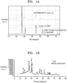
- the size of Li 2 S crystallites obtained in the XRD spectrum of the lithium sulfide composite may be, for example, less than about 9.9 nm (e.g., less than 9.9 nm), about 9.85 nm or less, about 9.83 nm or less, about 9.8 nm or less, about 9.5 nm or less, about 9.0 nm or less, or about 8.5 nm or less.
- the lithium sulfide composite (e.g., the lithium sulfide-LiI-carbon-based material composite) may include a solid solution of Li 2 S and Lil.
- the size of Li 2 S crystallites obtained in the XRP spectrum of the lithium sulfide composite may be in a range of, for example, about 1 nm to less than about 9.9 nm, about 1 nm to about 9.8 nm, about 2 nm to about 9.8 nm, about 2 nm to about 9.5 nm, about 2 nm to about 9.0 nm, about 2 nm to about 8.5 nm, or about 3 nm to about 8.5 nm.
- the lithium sulfide composite (e.g., the lithium sulfide-Lil-carbon-based material composite) may include a solid solution of Li 2 S and LiI.
- the lithium sulfide composite may have increased ionic conductivity by including a solid solution of Li 2 S and Lil.
- the solid solution of Li 2 S and LiI may include alkali metal ions arranged in Li 2 S crystallites, and thus, the ionic conductivity of the solid solution of Li 2 S and LiI may be improved compared to the ionic conductivity of Li 2 S.
- the ionic conductivity of the composite may be improved, and the internal resistance of the composite may be reduced.
- the cycle characteristics of a secondary battery including the composite cathode active material may be improved.
- the high-rate characteristics of a secondary battery including such a composite cathode active material may be improved.
- the Li 2 S-LiI-carbon-based material composite may be distinguished from a simple blend of Li 2 S, Lil, and a carbon-based material.
- the simple blend of Li 2 S, Lil, and a carbon-based material may provide high interfacial resistance by failing to maintain a dense interface between the Li 2 S, the Lil, and the carbon-based material, which may result in deteriorated lifespan characteristics of a secondary battery.
- a molar ratio of Li 2 S to LiI in the composite may be in a range of, for example, about 50:50 to about 95:5, about 60:40 to about 95:5, about 60:40 to about 90:10, about 65:35 to about 90:10, about 65:35 to about 85:15, or about 70:30 to about 85:15.
- the molar ratio of Li 2 S to LiI in the composite may be in a range of, for example, about 50:50 to about 95:5, about 50:50 to about 90:10, about 50:50 to about 85:15, about 50:50 to about 80:20, about 50:50 to about 75:25, or about 50:50 to about 70:30.
- the carbon nanostructure may be, for example, carbon nanotubes, carbon nanofibers, carbon nanobelts, carbon nanorods, graphene, or a combination thereof.
- the carbon-based material may be, for example, a porous carbon-based material or a non-porous carbon-based material.
- the porous carbon-based material may include, for example, periodic and ordered two-dimensional or three-dimensional pores.
- the porous carbon-based material may be, for example, carbon black such as Ketjen black, acetylene black, Denka black, thermal black, channel black, and/or the like, graphite, activated carbon, or a combination thereof.
- the carbon-based material may be in the form of, for example, particles, a sheet, a flake, and/or the like, but the present disclosure is not limited thereto and any carbon-based material that may be utilized in the art is possible.
- the amount of the carbon-based material included in the composite may be in a range of, for example, about 1 wt% to about 20 wt%, about 5 wt% to about 20 wt%, or about 10 wt% to about 20 wt%, with respect to the total weight of the composite. If (e.g., when) the amount of the carbon-based material is too large, the energy density of a secondary battery may deteriorate. If (e.g., when) the amount of the carbon-based material is too small, the electronic conductivity of the composite may be reduced, resulting in increased internal resistance of the composite cathode active material. As a result, the cycle characteristics of a secondary battery may deteriorate.
- a first peak that appears (e.g., exists) at a diffraction angle 2 ⁇ of 27° ⁇ 2.0° corresponding to a (111) crystal plane of Li 2 S may have a first diffraction angle
- a second peak that appears (e.g., exists) at a diffraction angle 2 ⁇ of 27° ⁇ 2.0° corresponding to a (111) crystal plane of Li 2 S in an XRD spectrum of Li 2 S utilized in the preparation of the composite may have a second diffraction angle
- the first diffraction angle may be smaller than the second diffraction angle.
- the position of the first peak may be shifted to a low angle compared to the position of the second peak.
- the Li 2 S-LiI-carbon-based material composite may have a reduced crystallite size compared to Li 2 S utilized in the preparation of the composite. Due to the reduced crystallite size of the Li 2 S-LiI-carbon-based material composite, a change in volume of crystallites during charging and discharging may be reduced, and thus, a change in volume of the composite including a plurality of crystallites during charging and discharging may be reduced. The occurrence of defects such as cracks in the composite cathode active material including such a composite during charging and discharging may be suppressed or reduced. As a result, the cycle characteristics of a secondary battery including the composite cathode active material may be improved.
- the first peak that appears (e.g., exists) at a diffraction angle 2 ⁇ of 27° ⁇ 2.0° corresponding to a (111) crystal plane of Li 2 S may have a first full width at half maximum (FWHM1)
- the second peak that appears (e.g., exists) at a diffraction angle 2 ⁇ of 27° ⁇ 2.0° corresponding to a (111) crystal plane of Li 2 S in an XRD spectrum of Li 2 S utilized in the preparation of the composite may have a second full width at half maximum (FWHM2)
- the first full width at half maximum may be greater than the second full width at half maximum.
- the Li 2 S-LiI-carbon-based material composite may have increased lattice strain compared to Li 2 S utilized in the preparation of the composite.
- Li 2 S and LiI may form a solid solution, and thus, the Li 2 S-LiI-carbon-based material composite may have increased lattice strain.
- a secondary battery including the composite cathode active material may have reduced internal resistance and improved cycle characteristics.
- the particle size of the composite cathode active material i.e., the size of composite particles, may be, for example, 10 ⁇ m or less, 8 ⁇ m or less, 5 ⁇ m or less, 2 ⁇ m or less, 1.5 ⁇ m or less, or 1 ⁇ m or less.
- the size of the composite particles may be in a range of, for example, about 1 ⁇ m to about 10 ⁇ m, about 2 ⁇ m to about 10 ⁇ m, about 2 ⁇ m to about 8 ⁇ m, or about 3 ⁇ m to about 8 ⁇ m.
- the size of the composite particles may be in a range of, for example, about 0.1 ⁇ m to about 10 ⁇ m, about 0.1 ⁇ m to about 8 ⁇ m, about 0.1 ⁇ m to about 5 ⁇ m, about 0.1 ⁇ m to about 2 ⁇ m, about 0.1 ⁇ m to about 1.5 ⁇ m, or about 0.1 ⁇ m to about 1 ⁇ m.
- the cathode mixture comprises composite particles having an average particle diameter of 5 micrometer ( ⁇ m) or less.
- the size of the composite particles is within the described ranges, a change in the volume thereof during charging and discharging may be suppressed or reduced, and thus, deterioration of the composite cathode active material including the composite during charging and discharging may be suppressed or reduced. If (e.g., when) the size of the composite particles is too large, the deterioration of the composite cathode active material including the composite may be accelerated due to an increased change in the volume of the composite during charging and discharging. As a result, the cycle characteristics of a secondary battery including such a composite cathode active material may deteriorate.
- the size of M 2 S particles included in the composite cathode active material i.e., the size of M 2 S particles included in the composite, may be, for example, 2 ⁇ m or less, 1.5 ⁇ m or less, or 1 ⁇ m or less.
- the size of the M 2 S particles may be in a range of, for example, about 0.1 ⁇ m to about 2 ⁇ m, about 0.1 ⁇ m to about 1.5 ⁇ m, or about 0.1 ⁇ m to about 1 ⁇ m.
- the size of the M 2 S particles is within the described ranges, a change in the volume thereof during charging and discharging may be suppressed or reduced, and thus, deterioration of the composite cathode active material including the composite during charging and discharging may be suppressed or reduced. If (e.g., when) the size of the M 2 S particles is too large, the deterioration of the composite cathode active material including the composite may be accelerated due to an increased change in the volume of the composite during charging and discharging. As a result, the cycle characteristics of a secondary battery including such a composite cathode active material may deteriorate.
- the cycle characteristics for example, lifespan characteristics of a secondary battery including the cathode active material may be improved.
- the size of the composite particles for example, the particle diameter of the composite may be measured, for example, by a laser diffraction method, a scanning electron microscope, and/or the like.
- the particle diameter of the composite may be, for example, an arithmetic mean value of the particle diameters of a plurality of particles, as measured by utilizing software in a scanning electron microscope image.
- the composite may include a carbon-based material, and the carbon-based material may include, for example, a fibrous carbon-based material.
- the composite may have further improved electronic conductivity by including the fibrous carbon-based material. Due to the fibrous carbon-based material included in the composite, electronic conduction may occur more easily from the surface to the inside of the composite. The internal resistance of the composite cathode active material including the composite may be reduced, and the cycle characteristics of an all-solid-state secondary battery including the composite cathode active material may be further improved.
- the aspect ratio of the fibrous carbon-based material may be, for example, 2 or more, 3 or more, 4 or more, 5 or more, 10 or more, or 20 or more.
- the aspect ratio of the fibrous carbon-based material may be in a range of, for example, about 2 to about 30, about 3 to about 30, about 4 to about 30, about 5 to about 30, about 10 to about 30, or about 20 to about 30.
- the aspect ratio of the fibrous carbon-based material may be in a range of, for example, about 2 to about 30, about 2 to about 20, about 2 to about 10, about 2 to about 8, about 2 to about 5, or about 2 to about 4. If (e.g., when) the aspect ratio of the fibrous carbon-based material is within the described ranges, the overall electronic conductivity of the composite may be improved, and the imbalance of local electronic conductivity in the composite may be further reduced.
- the fibrous carbon-based material may be, for example, a carbon nanostructure.
- the carbon nanostructure may include, for example, carbon nanofibers (CNFs), carbon nanotubes (CNTs), carbon nanobelts, carbon nanorods, or a combination thereof.
- the carbon nanostructure may form a primary carbon nanostructure including (e.g., consisting of) one carbon nanostructure and a secondary carbon nanostructure in which a plurality of carbon nanostructures is (e.g., are) aggregated.
- the diameter of the primary carbon nanostructure may be in a range of, for example, about 1 nm to about 200 nm, about 1 nm to about 150 nm, about 1 nm to about 100 nm, about 1 nm to about 50 nm, about 1 nm to about 30 nm, or about 1 nm to about 20 nm.
- the length of the primary carbon nanostructure may be in a range of, for example, about 10 nm to about 2 ⁇ m, about 10 nm to about 1.5 ⁇ m, about 10 nm to about 1 ⁇ m, about 10 nm to about 500 nm, about 10 nm to about 400 nm, about 10 nm to about 300 nm, about 10 nm to about 200 nm, or about 10 nm to about 100 nm.
- the diameter and length of the primary carbon nanostructure may be measured from a scanning electron microscope (SEM) image or a transmission electron microscope (TEM) image. In other embodiments, the diameter and/or length of the primary carbon nanostructure may be measured by a laser diffraction method.
- the secondary carbon nanostructure may be a structure formed by assembling primary carbon nanostructures to form a bundle type or kind or rope type or kind in whole or in part.
- the secondary carbon nanostructure may include, for example, a bundle-type or kind carbon nanostructure, a rope-type or kind carbon nanostructure, or a combination thereof.
- the diameter of the secondary carbon nanostructure may be in a range of, for example, about 2 nm to about 200 nm, about 3 nm to about 150 nm, about 5 nm to about 100 nm, about 5 nm to about 50 nm, about 5nm to about 30 nm, or about 5 nm to about 20 nm.
- the length of the secondary carbon nanostructure may be in a range of, for example, about 20 nm to about 2 ⁇ m, about 30 nm to about 1.5 ⁇ m, about 50 nm to about 1 ⁇ m, about 50 nm to about 500 nm, about 50 nm to about 400 nm, about 50 nm to about 300 nm, about 50 nm to about 200 nm, or about 50 nm to about 100 nm.
- the diameter and length of the secondary carbon nanostructure may be measured from a scanning electron microscope (SEM) image or by utilizing an optical microscope. In other embodiments, the diameter and/or length of the secondary carbon nanostructure may be measured by a laser diffraction method.
- the secondary carbon nanostructure may be dispersed in a solvent and/or the like to be converted into a primary carbon nanostructure, which may then be utilized in the preparation of the composite.
- the composite may include, for example, about 1 part by weight to about 80 parts by weight of Li 2 S, about 1 part by weight to about 40 parts by weight of Lil, and about 1 part by weight to about 20 parts by weight of the carbon-based material, with respect to 100 parts by weight of the composite. If (e.g., when) the amounts of M 2 S, the alkali metal salt, and the carbon-based material in the composite are within the described ranges, the composite cathode active material including the composite may exhibit excellent or suitable ionic conductivity and/or electronic conductivity.
- a cathode according to one or more embodiments may be manufactured by, for example, the following method, but the present disclosure is not limited thereto and the manufacturing method may vary depending on required conditions.
- the method may include: mildly mixing a lithium sulfide composite and a solid electrolyte to obtain a cathode mixture; and providing the cathode mixture onto a cathode current collector, followed by drying, to thereby complete the manufacture of a cathode.
- the mild mixing may be mortar mixing, thinky mixing, blade mixing, or a combination thereof.
- the cathode mixture may further include a binder.
- the binder may be, for example, styrene-butadiene rubber (SBR), polytetrafluoroethylene, polyvinylidene fluoride, polyethylene, and/or the like, but the present disclosure is not limited thereto and any binder utilized in the art is possible.
- SBR styrene-butadiene rubber
- the amount of the binder included in a cathode active material layer may be in a range of, for example, about 1 wt% to about 10 wt% with respect to a total weight of the cathode active material layer. In some embodiments, the binder may not be provided.
- Binder Binder
- a cathode active material layer 12 may further include a binder.
- the binder may be, for example, styrene-butadiene rubber (SBR), polytetrafluoroethylene, polyvinylidene fluoride, polyethylene, and/or the like, but the present disclosure is not limited thereto and any binder utilized in the art is possible.
- the amount of the binder included in the cathode active material layer 12 may be in a range of, for example, about 1 wt% to about 10 wt% with respect to a total weight of the cathode active material layer 12. In some embodiments, the binder may not be provided (e.g., be excluded).
- the cathode active material layer 12 may further include, for example, additives such as a filler, a coating agent, a dispersant, an ion-conductive adjuvant, and/or the like, in addition to the cathode active material, the solid electrolyte, the binder, and the conductive material as described herein.
- additives such as a filler, a coating agent, a dispersant, an ion-conductive adjuvant, and/or the like, in addition to the cathode active material, the solid electrolyte, the binder, and the conductive material as described herein.
- the filler As the filler, the coating agent, the dispersant, the ion-conductive adjuvant, and/or the like that may be included in the cathode active material layer 12, suitable materials generally utilized in electrodes of all-solid-state secondary batteries may be utilized.
- a cathode current collector 11 may include or be made of, for example, indium (In), copper (Cu), magnesium (Mg), stainless steel, titanium (Ti), iron (Fe), cobalt (Co), nickel (Ni), zinc (Zn), aluminum (Al), germanium (Ge), lithium (Li), or any alloy thereof in the form of a plate, foil, and/or the like.
- the cathode current collector 11 may not be provided.
- the thickness of the cathode current collector 11 may be in a range of, for example, about 1 ⁇ m to about 100 ⁇ m, about 1 ⁇ m to about 50 ⁇ m, about 5 ⁇ m to about 25 ⁇ m, or about 10 ⁇ m to about 20 ⁇ m.
- the cathode current collector 11 may include, for example, a base film and a metal layer on at least one side (e.g., on both (e.g., simultaneously) sides) of the base film.
- the base film may include, for example, a polymer.
- the polymer may be, for example, a thermoplastic polymer.
- the polymer may include, for example, polyethylene terephthalate (PET), polyethylene (PE), polypropylene (PP), polybutylene terephthalate (PBT), polyimide (PI), or a combination thereof.
- the base film may be, for example, an insulator.
- the metal layer may include, for example, indium (In), copper (Cu), magnesium (Mg), stainless steel, titanium (Ti), iron (Fe), cobalt (Co), nickel (Ni), zinc (Zn), aluminum (Al), germanium (Ge), or an alloy thereof.
- the metal layer may serve as an electrochemical fuse and break in case of overcurrent, thus performing a short-circuit prevention function.
- the limit current and the maximum current may be adjusted by adjusting the thickness of the metal layer.
- the metal layer may be plated or deposited on the base film. If (e.g., when) the thickness of the metal layer is reduced, the limit current and/or the maximum current of the cathode current collector 11 may be reduced, and thus, the stability of a lithium battery in the event of short circuit may be improved.
- a lead tab may be added on the metal layer for connection to the outside.
- the lead tab may be welded to the metal layer or a metal layer/base film stack by ultrasonic welding, laser welding, spot welding, and/or the like.
- the metal layer may be electrically connected to the lead tab while the base film and/or the metal layer is melted during welding. To make welding between the metal layer and the lead tab more rigid, a metal chip may be added between the metal layer and the lead tab.
- the metal chip may be foil of the same material as a metal of the metal layer.
- the metal chip may be, for example, metal foil or metal mesh.
- the metal chip may be, for example, aluminum foil, copper foil, SUS foil, and/or the like.
- the lead tab may be welded to a metal chip/metal layer stack or a metal chip/metal layer/base film stack by welding to the lead tab after the metal chip is provided on the metal layer.
- the metal layer or the metal layer/metal chip stack may be electrically connected to the lead tab while the base film, the metal layer, and/or the metal chip are melted during welding.
- a metal chip and/or a lead tab may be added on a portion of the metal layer.
- the base film may have a thickness of, for example, about 1 ⁇ m to about 50 ⁇ m, about 1.5 ⁇ m to about 50 ⁇ m, about 1.5 ⁇ m to about 40 ⁇ m, or about 1 ⁇ m to about 30 ⁇ m. If (e.g., when) the thickness of the base film is within the described ranges, the weight of an electrode assembly may be more effectively reduced.
- the base film may have a melting point of, for example, about 100 °C to about 300 °C, about 100 °C to about 250 °C, or about 100 °C to about 200 °C. If (e.g., when) the melting point of the base film is within the described ranges, the base film may be melted and easily coupled to the lead tab in the lead tab welding process.
- the metal layer may have a thickness of, for example, about 0.01 ⁇ m to about 3 ⁇ m, about 0.1 ⁇ m to about 3 ⁇ m, about 0.1 ⁇ m to about 2 ⁇ m, or about 0.1 ⁇ m to about 1 ⁇ m. If (e.g., when) the thickness of the metal layer is within the described ranges, the stability of an electrode assembly may be secured while maintaining conductivity.
- the metal chip may have a thickness of, for example, about 2 ⁇ m to about 10 ⁇ m, about 2 ⁇ m to about 7 ⁇ m, or about 4 ⁇ m to about 6 ⁇ m.
- connection between the metal layer and the lead tab may be more facilitated. If (e.g., when) the cathode current collector 11 has this structure, the weight of the cathode may be reduced, resulting in improved energy density of the cathode and a lithium battery.
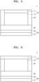
- a cathode 10 includes the cathode current collector 11, and the cathode active material layer 12 provided on one side of the cathode current collector 11.
- An inactive member 40 may be provided on a side surface of the cathode 10. Referring to FIG. 5 , the inactive member 40 may be provided on side surfaces of the cathode active material layer 12 and the cathode current collector 11. Referring to FIG. 6 , the inactive member 40 may be arranged on a side surface of the cathode active material layer 12 and provided between a solid electrolyte layer 30 and the cathode current collector 11 facing the electrolyte layer 30. The inactive member 40 may not be arranged on a side surface of the cathode current collector 11.
- the electrolyte layer 30 may be, for example, a solid electrolyte layer.
- the occurrence of cracks in the electrolyte layer 30 may be prevented or reduced during manufacturing and/or charging and discharging of an all-solid-state secondary battery 1, resulting in improved cycle characteristics of the all-solid-state secondary battery 1.
- uneven pressure may be applied to the electrolyte layer 30 in contact with the cathode 10 during manufacturing and/or charging and discharging of the all-solid-state secondary battery 1, and thus, cracks occur in the electrolyte layer 30 and lithium metal grows through this, resulting in an increased possibility of a short circuit.
- the thickness of the inactive member 40 may be greater than or equal to the thickness of the cathode active material layer 12. In other embodiments, in the all-solid-state secondary battery 1, the thickness of the inactive member 40 may be substantially the same as the thickness of the cathode 10. Thus, substantially uniform pressure may be applied between the cathode 10 and the electrolyte layer 30, and the cathode 10 and the electrolyte layer 30 may be sufficiently in close contact with each other, and thus, the interfacial resistance between the cathode 10 and the electrolyte layer 30 may be reduced. In some embodiments, the electrolyte layer 30 may be sufficiently sintered during manufacturing of the all-solid-state secondary battery 1 by pressing, and thus, the internal resistance of the electrolyte layer 30 and the all-solid-state secondary battery 1 including the same may be reduced.
- the inactive member 40 may contact the electrolyte layer 30 while around (e.g., surrounding) a side surface of the cathode 10. Thus, cracks in the electrolyte layer 30, caused by a pressure difference during a pressing process in the electrolyte layer 30 that is not in contact with the cathode 20, may be effectively suppressed or reduced.
- the inactive member 40 may surround a side surface of the cathode 10 and may be separated from the anode 20, for example, a first anode active material layer 22.
- the inactive member 40 may surround a side surface of the cathode 10 and contact the electrolyte layer 30, and may be separated from the anode 20.
- the possibility of a short circuit that occurs by physical contact between the cathode 10 and the first anode active material layer 22, overcharging of lithium, and/or the like may be suppressed or reduced.
- the inactive member 40 may be arranged on a side surface of the cathode active material layer 12 and at the same time, may be arranged on a side surface of the cathode current collector 11, and thus, the possibility of a short circuit that occurs by contact between the cathode current collector 11 and the anode 20 may be more effectively suppressed or reduced.
- the inactive member 40 may extend from a side surface of the cathode 10 to an end portion of the electrolyte layer 30. Due to the configuration in which the inactive member 40 extends to the end portion of the electrolyte layer 30, the occurrence of cracks in the end portion of the electrolyte layer 30 may be suppressed or reduced.
- the end portion of the electrolyte layer 30 may be the outermost portion in contact with a side surface of the electrolyte layer 30.
- the inactive member 40 may extend to the outermost portion in contact with the side surface of the electrolyte layer 30.
- the inactive member 40 may be separated from an anode 20, for example, the first anode active material layer 22.
- the inactive member 40 may extend to the end portion of the electrolyte layer 30, but may not contact the anode 20.
- the inactive member 40 may fill a space extending from a side surface of the cathode 10 to the end portion of the electrolyte layer 30.
- the width of the inactive member 40 extending from the side surface of the cathode 10 to the end portion of the electrolyte layer 30 may be in a range of, for example, about 1 % to about 30 %, about 1 % to about 25 %, about 1 % to about 20 %, about 1 % to about 15 %, about 1 % to about 10 %, or about 1 % to about 5 % of the width between a side surface of the cathode 10 and another side surface thereof facing the side surface. If (e.g., when) the width of the inactive member 40 is too large, the energy density of the secondary battery 1 may be reduced. If (e.g., when) the width of the inactive member 40 is too small, the effect of disposing the inactive member 40 may be insignificant.
- the area of the cathode 10 may be smaller than the area of the electrolyte layer 30 in contact with the cathode 10.
- the inactive member 40 may be arranged to surround a side surface of the cathode 10, to compensate for the difference in area between the cathode 10 and the electrolyte layer 30.
- the area of the inactive member 40 compensates for the difference between the area of the cathode 10 and the area of the electrolyte layer 30, and thus, the occurrence of cracks in electrolyte layer 30 due to a pressure difference during a pressing process may be effectively suppressed or reduced.
- a sum of the area of the cathode 10 and the area of the inactive member 40 may be equal to the area of the electrolyte layer 30.
- the electrolyte layer 30 may be, for example, a solid electrolyte layer.
- the area of the cathode 10 may be, for example, less than 100 %, 99 % or less, 98 % or less, 97 % or less, 96 % or less, or 95 % or less of the area of the electrolyte layer 30.
- the area of the cathode 10 may be in a range of, for example, at least about 50 % and less than 100 %, about 50 % to about 99 %, about 55 % to about 98 %, about 60 % to about 97 %, about 70 % to about 96 %, about 80 % to about 95 %, or about 85 % to about 95 % of the area of the electrolyte layer 30.
- the area of the cathode 10 may be equal to the area of the cathode active material layer 12.
- the area of the cathode 10 may be equal to the area of the cathode current collector 11.
- the area of the inactive member 40 may be, for example, 50 % or less, 40 % or less, 30 % or less, 20 % or less, or 10 % or less of the area of the cathode 10.
- the area of the inactive member 40 may be in a range of, for example, about 1 % to about 50 %, about 5 % to about 40 %, about 5 % to about 30 %, about 5 % to about 20 %, or about 5 % to about 15 % of the area of the cathode 10.
- An area S1 of the cathode 10 may be smaller than an area S4 of an anode current collector 21.
- the area S1 of the cathode 10 may be, for example, less than 100 %, 99 % or less, 98 % or less, 97 % or less, 96 % or less, or 95 % or less of the area S4 of the anode current collector 21.
- the area S1 of the cathode 10 may be in a range of, for example, at least about 50 % and less than about 100 %, about 50 % to about 99 %, about 55 % to about 98 %, about 60 % to about 97 %, about 70 % to about 96 %, about 80 % to about 95 %, or about 85 % to about 95 % of the area S4 of the anode current collector 21.
- the area S4 of the anode current collector 21 may be equal to, for example, the area of the anode 20.
- the area S4 of the anode current collector 21 may be equal to, for example, the area of the first anode active material layer 22.
- the "same" area, length, width, thickness and/or shape is intended to exclude cases of having a different area, length, width, thickness and/or shape and include all the cases of having “substantially the same” area, length, width, thickness and/or shape.
- the "same" area, length, width and/or thickness refers to that the unintentional difference in area, length, width, and/or thickness between objects to be compared is in a range of, for example, less than 3 %, less than 2 %, less than 1 %, less than 0.5 %, or less than 0.1 %.
- the thickness of the inactive member 40 may be greater than the thickness of the first anode active material layer 22.
- the thickness of the first anode active material layer 22 may be, for example, 50% or less, 40% or less, 30% or less, 20% or less, or 10% or less of the thickness of the inactive member 40.
- the thickness of the first anode active material layer 22 may be in a range of, for example, about 1 % to about 50 %, about 1 % to about 40 %, about 1 % to about 30 %, about 1 % to about 20 %, or about 1 % to about 10 % of the thickness of the inactive member 40.
- the inactive member 40 may be a gasket.
- a gasket By utilizing a gasket as the inactive member 40, the occurrence of cracks in the electrolyte layer 30 due to a pressure difference during a pressing process may be effectively suppressed or reduced.
- the inactive member 40 may have, for example, a single-layered structure. In other embodiments, although not shown in the drawings, the inactive member 40 may have a multi-layered structure. In the inactive member 40 having a multi-layered structure, respective layers may have different compositions. The inactive member having a multi-layered structure may have, for example, a two-layered structure, a three-layered structure, a four-layered structure, or a five-layered structure. The inactive member 40 having a multi-layered structure may include, for example, at least one adhesive layer and at least one support layer.
- the first fibrous material may include, for example, at least one selected from among pulp fibers, insulating polymer fibers, and ion-conducting polymer fibers.
- the matrix may have improved strength by including the reinforcing material. Thus, the matrix may prevent or reduce excessive volume changes during charging and discharging of the all-solid-state secondary battery 1 and prevent or reduce deformation of the all-solid-state secondary battery 1.
- the reinforcing material included in the matrix may include, for example, a second fibrous material.
- the second fibrous material may be, for example, a material having an aspect ratio of 3 or more, 5 or more, or 10 or more.
- the first fibrous material may be, for example, a material having an aspect ratio of about 3 to about 100, about 5 to about 100, or about 10 to about 100.
- the second fibrous material may be, for example, a flame-retardant material.
- the second fibrous material is a flame-retardant material
- ignition due to thermal runaway that occurs during processes of charging and discharging of the all-solid-state secondary battery 1 or occurs due to external shock may be effectively suppressed or reduced.
- the second fibrous material may be, for example, glass fiber, metal oxide fiber, ceramic fiber, and/or the like.
- the flame-retardant inactive member may include a filler, in addition to the matrix.
- the filler may be provided inside the matrix, on a surface of the matrix, or both (e.g., simultaneously) inside and on the surface of the matrix.
- the filler may be, for example, an inorganic material.
- the filler included in the flame-retardant inactive member may be, for example, a moisture getter.
- the filler may be to absorb moisture at a temperature of, for example, less than 100 °C, thereby removing moisture remaining in the all-solid-state secondary battery 1, and thus, the deterioration of the all-solid-state secondary battery 1 may be prevented or reduced.
- the filler may release the absorbed moisture, and thus, ignition of the all-solid-state secondary battery 1 may be effectively suppressed or reduced.
- the filler may be, for example, a flame retardant.
- the filler may be a metal hydroxide having hygroscopic properties.
- Examples of the metal hydroxide included in the filler may include Mg(OH) 2 , Fe(OH) 3 , Sb(OH) 3 , Sn(OH) 4 , Tl(OH) 3 , Zr(OH) 4 , Al(OH) 3 , or a combination thereof.
- the amount of the filler included in the flame-retardant inactive member may be in a range of, for example, about 10 parts by weight to about 80 parts by weight, about 20 parts by weight to about 80 parts by weight, about 30 parts by weight to about 80 parts by weight, about 40 parts by weight to about 80 parts by weight, about 50 parts by weight to about 80 parts by weight, about 60 parts by weight to about 80 parts by weight, or about 65 parts by weight to about 80 parts by weight, with respect to 100 parts by weight of the flame-retardant inactive member 40.
- the flame-retardant inactive member may further include, for example, a binder.
- the binder may include, for example, a curable polymer or a non-curable polymer.
- the curable polymer may be a polymer that may be (e.g., gets) cured by heat and/or pressure.
- the curable polymer may be solid at room temperature.
- Examples of the flame-retardant inactive member 40 may include a heat-press curable film and/or a cured product thereof.
- the heat-press curable film may be, for example, TSA-66 manufactured by Toray.
- the flame-retardant inactive member 40 may further include other materials, in addition to the herein-described substrate, reinforcing material, filler, and binder.
- the flame-retardant inactive member may further include at least one selected from among paper, an insulating polymer, an ion conductive polymer, an insulating inorganic material, an oxide-based solid electrolyte, and a sulfide-based solid electrolyte.
- the insulating polymer may be, for example, an olefin-based polymer such as polypropylene (PP) or polyethylene (PE).
- the density of the substrate or reinforcing material included in the flame-retardant inactive member may be in a range of, for example, about 10 % to about 300 %, about 10 % to about 150 %, about 10 % to about 140 %, about 10 % to about 130 %, or about 10 % to about 120 % of the density of the cathode active material included in the cathode active material layer 12.
- the inactive member 40 may be a member that does not include an electrochemically active material, for example, an electrode active material.
- the electrode active material may be a material capable of absorbing/desorbing lithium.
- the inactive member 40 may be a member formed of any material utilized in the art that is not an electrode active material.
- Anode Anode active material
- the anode 20 includes the first anode active material layer 22.
- the first anode active material layer 22 may include, for example, an anode active material and a binder.
- the anode active material included in the first anode active material layer 22 may be, for example, an anode material capable of forming an alloy or compound with lithium.
- the anode active material included in the first anode active material layer 22 may have, for example, a particle form.
- the average particle diameter of the anode active material in particle form may be, for example, 4 ⁇ m or less, 3 ⁇ m or less, 2 ⁇ m or less, 1 ⁇ m or less, 500 nm or less, 300 nm or less, or 100 nm or less.
- the average particle diameter of the anode active material in particle form may be in a range of, for example, about 10 nm to about 4 ⁇ m, about 10 nm to about 3 ⁇ m, about 10 nm to about 2 ⁇ m, about 10 nm to about 1 ⁇ m, about 10 nm to about 500 nm, about 10 nm to about 300 nm, or about 10 nm to about 100 nm. If (e.g., when) the average particle diameter of the anode active material is within the described ranges, reversible absorption and/or desorption of lithium during charging and discharging may be more easily facilitated.
- the average particle diameter of the anode active material may be, for example, a median diameter (D50) measured by utilizing a laser particle size distribution analyzer.
- the anode active material included in the first anode active material layer 22 may include, for example, at least one selected from among a carbon-based anode active material and a metal or metalloid anode active material.
- the carbon-based anode active material may include, for example, amorphous carbon, crystalline carbon, porous carbon, or a combination thereof.
- the carbon-based anode active material may be, for example, amorphous carbon.
- the amorphous carbon may be, for example, carbon black (CB), acetylene black (AB), furnace black (FB), Ketjen black (KB), or graphene.
- CB carbon black
- AB acetylene black
- FB furnace black
- graphene graphene
- present disclosure is not limited thereto and any carbon that is classified as amorphous carbon in the art is possible.
- Amorphous carbon may be carbon that does not have crystallinity or has very low crystallinity and may be distinguished from crystalline carbon or graphitic carbon.
- the carbon-based anode active material may be, for example, porous carbon.
- the pore volume of the porous carbon may be in a range of, for example, about 0.1 cubic centimeter per gram (cc/g) to about 10.0 cc/g, about 0.5 cc/g to about 5 cc/g, or about 0.1 cc/g to about 1 cc/g.
- the average pore diameter of the porous carbon may be in a range of, for example, about 1 nm to about 50 nm, about 1 nm to about 30 nm, or about 1 nm to about 10 nm.
- the BET specific surface area of the porous carbon may be in a range of, for example, about 100 square meter per gram (m 2 /g) to about 3,000 m 2 /g.
- the BET specific surface area of the porous carbon may be measured, for example, in accordance with ISO 9277:2022.
- the metal or metalloid anode active material may include at least one selected from among gold (Au), platinum (Pt), palladium (Pd), silicon (Si), silver (Ag), aluminum (Al), bismuth (Bi), tin (Sn), and zinc (Zn).
- Au gold
- platinum Pt
- palladium Pd
- silicon Si
- silver Ag
- aluminum Al
- bismuth Bi
- tin Sn
- Zn zinc
- the present disclosure is not limited thereto and any metal anode active material or metalloid anode active material that forms an alloy or compound with lithium utilized in the art is possible.
- nickel (Ni) does not form an alloy with lithium, and thus is not a metal anode active material.
- the first anode active material layer 22 may include one of these anode active materials, or a mixture of a plurality of different anode active materials.
- the first anode active material layer 22 may include amorphous carbon alone, or may include at least one selected from among gold (Au), platinum (Pt), palladium (Pd), silicon (Si), silver (Ag), aluminum (Al), bismuth (Bi), tin (Sn), and zinc (Zn).
- the first anode active material layer 22 may include a mixture of amorphous carbon and at least one selected from among gold (Au), platinum (Pt), palladium (Pd), silicon (Si), silver (Ag), aluminum (Al), bismuth (Bi), tin (Sn), and zinc (Zn).
- a mixing ratio of the mixture of amorphous carbon and gold and/or the like may be in a range of, for example, about 99:1 to about 1:99, about 10:1 to about 1:2, about 5:1 to about 1:1, or about 4:1 to about 2:1.
- the present disclosure is not limited thereto and the mixing ratio may be selected depending on the required characteristics of the all-solid-state secondary battery 1. If (e.g., when) the anode active material has this composition, the cycle characteristics of the all-solid-state secondary battery 1 may be further improved.
- the anode active material included in the first anode active material layer 22 may include, for example, a mixture of primary particles consisting of amorphous carbon and secondary particles consisting of a metal or a metalloid.
- the metal or the metalloid may include, for example, at least one selected from among gold (Au), platinum (Pt), palladium (Pd), silicon (Si), silver (Ag), aluminum (Al), bismuth (Bi), tin (Sn), and zinc (Zn).
- the metalloid may be a semiconductor.
- the amount of the secondary particles may be in a range of about 1 wt% to about 99 wt%, about 1 wt% to about 60 wt%, about 8 wt% to about 60 wt%, about 10 wt% to about 50 wt%, about 15 wt% to about 40 wt%, or about 20 wt% to about 30 wt%, with respect to a total weight of the mixture. If (e.g., when) the amount of the secondary particles is within the described ranges, for example, the cycle characteristics of the all-solid-state secondary battery 1 may be further improved.
- the first anode active material layer 22 may include a composite anode active material.
- the composite anode active material may include, for example, a carbon-based support and a metal-based anode active material supported on the carbon-based support. If (e.g., when) the composite anode active material has such a structure, localization of the metal-based anode active material in the first anode active material layer may be prevented or reduced and substantially uniform distribution thereof may be obtained. As a result, the cycle characteristics of the all-solid-state secondary battery 1 including the first anode active material layer 22 may be further improved.
- the metal-based anode active material supported on the carbon-based support may include, for example, a metal, a metal oxide, a composite of a metal and a metal oxide, or a combination thereof.
- the metal may include gold (Au), platinum (Pt), palladium (Pd), silicon (Si), silver (Ag), aluminum (Al), bismuth (Bi), tin (Sn), tellurium (Te), and zinc (Zn).
- Non-limiting examples of the metal oxide may include gold (Au) oxide, platinum (Pt) oxide, palladium (Pd) oxide, silicon (Si) oxide, silver (Ag) oxide, aluminum (Al) oxide, bismuth (Bi) oxide, tin (Sn) oxide, tellurium (Te) oxide, and zinc (Zn) oxide.
- the metal oxide may include, for example, Au x O y where 0 ⁇ x ⁇ 2 and 0 ⁇ y ⁇ 3, Pt x O y where 0 ⁇ x ⁇ 1 and 0 ⁇ y ⁇ 2, Pd x O y where 0 ⁇ x ⁇ 1 and 0 ⁇ y ⁇ 1, Si x O y where 0 ⁇ x ⁇ 1 and 0 ⁇ y ⁇ 2, Ag x O y where 0 ⁇ x ⁇ 2 and 0 ⁇ y ⁇ 1, Al x O y where 0 ⁇ x ⁇ 2 and 0 ⁇ y ⁇ 3, Bi x O y where 0 ⁇ x ⁇ 2 and 0 ⁇ y ⁇ 3, Sn x O y where 0 ⁇ x ⁇ 1 and 0 ⁇ y ⁇ 2, Te x O y where 0 ⁇ x ⁇ 1 and 0 ⁇ y ⁇ 3, Zn x O y where 0 ⁇ x ⁇ 1 and 0 ⁇ y ⁇ 1, or a combination thereof.
- the composite of a metal and a metal oxide may include, for example, a composite of Au and Au x O y where 0 ⁇ x ⁇ 2 and 0 ⁇ y ⁇ 3, a composite of Pt and Pt x O y where 0 ⁇ x ⁇ 1 and 0 ⁇ y ⁇ 2, a composite of Pd and Pd x O y where 0 ⁇ x ⁇ 1 and 0 ⁇ y ⁇ 1, a composite of Si and Si x O y where 0 ⁇ x ⁇ 1 and 0 ⁇ y ⁇ 2, a composite of Ag and Ag x O y where 0 ⁇ x ⁇ 2 and 0 ⁇ y ⁇ 1, a composite of Al and Al x O y where 0 ⁇ x ⁇ 2 and 0 ⁇ y ⁇ 3, a composite of Bi and Bi x O y where 0 ⁇ x ⁇ 2 and 0 ⁇ y ⁇ 3, a composite of Sn and Sn x O y where 0 ⁇ x ⁇ 1 and 0 ⁇ y ⁇ 2, a composite of Te and Te x O y where 0 ⁇ x ⁇ 1 and 0 ⁇
- the carbon-based support may be, for example, amorphous carbon.
- the amorphous carbon may be, for example, carbon black (CB), acetylene black (AB), furnace black (FB), Ketjen black (KB), graphene, activated carbon, carbon nanofibers (CNFs), or carbon nanotubes (CNTs).
- CB carbon black
- AB acetylene black
- FB furnace black
- KB Ketjen black
- graphene activated carbon
- CNFs carbon nanofibers
- CNTs carbon nanotubes
- the carbon-based material may be, for example, a carbon-based anode active material.
- the composite anode active material may have, for example, a particle form.
- the particle diameter of the composite anode active material in particle form may be in a range of, for example, about 10 nm to about 4 ⁇ m, about 10 nm to about 1 ⁇ m, about 10 nm to about 500 nm, about 10 nm to about 200 nm, or about 10 nm to about 100 nm. If (e.g., when) the particle diameter of the composite anode active material is within the described ranges, reversible absorption and/or desorption of lithium during charging and discharging may be more facilitated.
- the metal-based anode active material supported on the support may have, for example, a particle form.
- the particle diameter of the metal-based anode active material may be in a range of, for example, about 1 nm to about 200 nm, about 1 nm to about 150 nm, about 5 nm to about 100 nm, or about 10 nm to about 50 nm.
- the carbon-based support may have, for example, a particle form.
- the particle diameter of the carbon-based support may be in a range of, for example, about 10 nm to about 2 ⁇ m, about 10 nm to about 1 ⁇ m, about 10 nm to about 500 nm, about 10 nm to about 200 nm, or about 10 nm to about 100 nm.
- the carbon-based support may be more uniformly arranged in the first anode active material layer.
- the carbon-based support may be, for example, nanoparticles having a particle diameter of 500 nm or less.
- the particle diameter of the composite anode active material, the particle diameter of the metal-based anode active material, and the particle diameter of the carbon-based support may be, for example, average particle diameters.
- the average particle diameter may be, for example, a median diameter (D50) measured by utilizing a laser particle size distribution analyzer. In other embodiments, the average particle diameter may be, for example, determined automatically by utilizing software from an electron microscope image, or may be determined manually by manual methods.
- the binder included in the first anode active material layer 22 may be, for example, styrene-butadiene rubber (SBR), polytetrafluoroethylene, polyvinylidene fluoride, polyethylene, a vinylidene fluoride/hexafluoropropylene copolymer, polyacrylonitrile, or polymethyl methacrylate.
- SBR styrene-butadiene rubber
- the binder may be a binder alone or a plurality of different binders.
- the first anode active material layer 22 may be stabilized on the anode current collector 21.
- the occurrence of cracks in the first anode active material layer 22 may be suppressed or reduced.
- the first anode active material layer 22 may be easily separated from the anode current collector 21.
- the first anode active material layer 22 may be prepared by, for example, applying a slurry, in which materials constituting the first anode active material layer 22 are dispersed, onto the anode current collector 21 and drying the slurry. By including the binder in the first anode active material layer 22, the anode active material may be stably dispersed in the slurry.
- the slurry is applied onto the anode current collector 21 by screen printing, it may be possible to suppress or reduce clogging of a screen (for example, clogging by aggregates of the anode active material).
- the first anode active material layer 22 may further include, for example, additives utilized in existing all-solid-state secondary batteries, such as a filler, a coating agent, a dispersant, and an ion-conductive adjuvant.
- additives utilized in existing all-solid-state secondary batteries such as a filler, a coating agent, a dispersant, and an ion-conductive adjuvant.
- the first anode active material layer 22 may further include a solid electrolyte.
- the solid electrolyte may be, for example, a material selected from solid electrolytes included in the solid electrolyte layer 30.
- the solid electrolyte included in the first anode active material layer 22 may serve as a reaction point where the formation of lithium metal starts in the first anode active material layer 22, serve as a space where the formed lithium metal is stored, or serve as a path for the transfer of lithium ions.
- the solid electrolyte may not be provided.
- the amount of the solid electrolyte may be large in an area adjacent to the electrolyte layer 30 and small in an area adjacent to the anode current collector 21.
- the solid electrolyte may have, for example, a concentration gradient in which the concentration decreases from the area adjacent to the electrolyte layer 30 to the area adjacent to the anode current collector 21.
- a ratio B/A of an initial charge capacity B of the first anode active material layer 22 to an initial charge capacity A of the cathode active material layer 12 may be in a range of, for example, about 0.005 to about 0.45.
- the initial charge capacity of the cathode active material layer 12 may be determined by charging from a 1 st open circuit voltage to a maximum charging voltage vs. Li/Li + .
- the initial charge capacity of the first anode active material layer 22 may be determined by discharging from a 2 nd open circuit voltage to 0.01 V vs. Li/Li + .
- the maximum charging voltage may be determined depending on the type or kind of cathode active material.
- the maximum charging voltage may be, for example, 1.5 V, 2.0 V, 2.5 V, 3.0 V, 3.5 V, 4.0 V, 4.2 V, or 4.3 V.
- the maximum charging voltage of Li 2 S or a Li 2 S composite may be 2.5 V vs. Li/Li + .
- the maximum charging voltage of Li 2 S or a Li 2 S composite may be 3.0 V vs. Li/Li + .
- the ratio B/A of the initial charge capacity B of the first anode active material layer 22 to the initial charge capacity A of the cathode active material layer 12 may be in a range of, for example, about 0.01 to about 0.3, about 0.01 to about 0.2, or about 0.05 to about 0.1.
- the initial charge capacity (milliampere hour (mAh)) of the cathode active material layer 12 may be obtained by multiplying the charge specific capacity (milliampere hour per gram (mAh/g)) of the cathode active material by the mass (g) of the cathode active material in the cathode active material layer 12. If (e.g., when) one or more suitable types (kinds) of cathode active materials are utilized, charge specific capacity x mass value may be calculated for each cathode active material, and the sum of these values may be the initial charge capacity of the cathode active material layer 12. Also, the initial charge capacity of the first anode active material layer 22 may be calculated in substantially the same way.
- the initial charge capacity of the first anode active material layer 22 may be obtained by multiplying the charge specific capacity (mAh/g) of the anode active material by the mass of the anode active material in the first anode active material layer 22. If (e.g., when) one or more suitable types (kinds) of anode active materials are utilized, charge specific capacity x mass value may be calculated for each anode active material, and the sum of these values may be the initial charge capacity of the first anode active material layer 22.
- the charge specific capacity of each of the cathode active material and the anode active material may be measured by utilizing an all-solid-state half-cell utilizing lithium metal as a counter electrode.
- the initial charge capacity of each of the cathode active material layer 12 and the first anode active material layer 22 may be directly measured by utilizing an all-solid-state half-cell at a constant current density of, for example, 0.1 milliampere per square centimeter (mA/cm 2 ).
- the measurement may be performed from the 1 st open circuit voltage (OCV) to the maximum charging voltage, e.g., an operating voltage of 3.0 V (vs. Li/Li + ).
- OCV open circuit voltage
- the measurement may be performed from the 2 nd open circuit voltage (OCV) to, for example, an operating voltage of 0.01 V vs. lithium metal.
- an all-solid-state half-cell having the cathode active material layer may be charged at a constant current of 0.1 mA/cm 2 from the 1 st open circuit voltage to 3.0 V, and an all-solid-state half-cell having the first anode active material layer may be charged at a constant current of 0.1 mA/cm 2 from the 2 nd open circuit voltage to 0.01 V.
- the current density during charging at a constant current may be, for example, 0.2 mA/cm 2 or 0.5 mA/cm 2 .
- the all-solid-state half-cell having the cathode active material layer may be charged, for example, from the 1 st open circuit voltage to 2.5 V, 2.0 V, 3.5 V, or 4.0 V.
- the maximum charging voltage of the cathode active material layer may be determined by the maximum voltage of a battery that satisfies the safety conditions in accordance with JISC8712:2015 of the Japanese Standards Association, the entire content of which is hereby incorporated by
- the first anode active material layer 22 becomes very thin, so that lithium dendrites formed between the first anode active material layer 22 and the anode current collector 21 during charging and discharging processes may collapse the first anode active material layer 22, and thus, the cycle characteristics of the all-solid-state secondary battery 1 are hardly improved.
- the energy density of the all-solid-state secondary battery 1 may be reduced and the internal resistance of the all-solid-state secondary battery 1 due to the first anode active material layer 22 may be increased, making it difficult to improve the cycle characteristics of the all-solid-state secondary battery 1.
- the thickness of the first anode active material layer 22 may be, for example, 50% or less, 40% or less, 30% or less, 20% or less, 10% or less, or 5% or less of the thickness of the cathode active material layer 12.
- the thickness of the first anode active material layer 22 may be in a range of, for example, about 1 % to about 50 %, about 1 % to about 40 %, about 1 % to about 30 %, about 1 % to about 20 %, about 1 % to about 10 %, or about 1% to about 5 % of the thickness of the cathode active material layer 12.
- the thickness of the first anode active material layer 22 may be in a range of, for example, about 1 ⁇ m to about 20 ⁇ m, about 2 ⁇ m to about 15 ⁇ m, or about 3 ⁇ m to about 10 ⁇ m. If (e.g., when) the thickness of the first anode active material layer 22 is too small, lithium dendrites formed between the first anode active material layer 22 and the anode current collector 21 may collapse the first anode active material layer 22, making it difficult for the all-solid-state secondary battery 1 to have improved cycle characteristics.
- the thickness of the first anode active material layer 22 is too large, the energy density of the all-solid-state secondary battery 1 may decrease and the internal resistance of the all-solid-state secondary battery 1 due to the first anode active material layer 22 may increase, making it difficult for the all-solid-state secondary battery 1 to have enhanced cycle characteristics. If (e.g., when) the thickness of the first anode active material layer 22 decreases, for example, the initial charge capacity of the first anode active material layer 22 may also be reduced.
- the all-solid-state secondary battery 1 may further include, for example, a second anode active material layer between the anode current collector 21 and the first anode active material layer 22.
- the second anode active material layer may be a metal layer including lithium or a lithium alloy.
- the metal layer may include lithium or a lithium alloy. Due to being a metal layer containing lithium, the second anode active material layer may serve as, for example, a lithium reservoir.
- the lithium alloy may be, for example, a Li-Al alloy, a Li-Sn alloy, a Li-In alloy, a Li-Ag alloy, a Li-Au alloy, a Li-Zn alloy, a Li-Ge alloy, or a Li-Si alloy.
- the second anode active material layer may be formed of one of these alloys or lithium, or may be formed of several types (kinds) of alloys.
- the second anode active material layer may be, for example, a plated layer.
- the second anode active material layer may be plated or deposited between the first anode active material layer 22 and the anode current collector 21 during the charging process of the all-solid-state secondary battery 1.
- the thickness of the second anode active material layer is not limited, but may be in a range of, for example, about 1 ⁇ m to about 500 ⁇ m, about 1 ⁇ m to about 200 ⁇ m, about 1 ⁇ m to about 150 ⁇ m, about 1 ⁇ m to about 100 ⁇ m, or about 1 ⁇ m to about 50 ⁇ m. If (e.g., when) the thickness of the second anode active material layer is too small, it may be difficult for the second anode active material layer to function as a lithium reservoir. If (e.g., when) the thickness of the second anode active material layer is too large, the mass and volume of the all-solid-state secondary battery 1 may increase and the cycle characteristics of the all-solid-state secondary battery 1 may rather deteriorate.
- the second anode active material layer may be, for example, provided between the anode current collector 21 and the first anode active material layer 22, before assembly of the all-solid-state secondary battery 1. If (e.g., when) the second anode active material layer is provided between the anode current collector 21 and the first anode active material layer 22 before assembly of the all-solid-state secondary battery 1, the second anode active material layer may serve as a lithium reservoir due to being a lithium-containing metal layer. For example, before the all-solid-state secondary battery 1 is assembled, lithium foil may be provided between the anode current collector 21 and the first anode active material layer 22.
- the energy density of the all-solid-state secondary battery 1 may increase because the second anode active material layer is not included during assembly of the all-solid-state secondary battery 1.
- the all-solid-state secondary battery 1 may be charged at a charging capacity that exceeds that of the first anode active material layer 22.
- the first anode active material layer 22 may be overcharged. At the beginning of charging, lithium may be absorbed into the first anode active material layer 22.
- the anode active material included in the first anode active material layer 22 may form an alloy or compound with lithium ions that have migrated from the cathode 10.
- the second anode active material layer may be a metal layer mainly including (e.g., consisting of) lithium (i.e., lithium metal).
- lithium in the first anode active material layer 22 and the second anode active material layer 24, for example, the metal layer may be ionized and migrate toward the cathode 10.
- the first anode active material layer 22 may serve as a protective layer for the second anode active material layer, for example, the metal layer, and at the same time, may serve to suppress or reduce the deposition and growth of lithium dendrites.
- the short circuit and capacity reduction of the all-solid-state secondary battery 1 may be suppressed or reduced, resulting in improved cycle characteristics of the all-solid-state secondary battery 1.
- the anode 20, i.e., the anode current collector 21, the first anode active material layer 22, and a region therebetween may be Li-free regions that do not contain Li in an initial state or completely discharged state of the all-solid-state secondary battery 1.
- Anode Anode current collector
- Anode current collectors 21, 21a, and 21b may include or be made of a material that does not react with lithium, for example, a material that does not form both (e.g., simultaneously) an alloy and/or a compound with lithium.
- Examples of materials constituting the anode current collector 21 may include copper (Cu), stainless steel, titanium (Ti), iron (Fe), cobalt (Co), and/or nickel (Ni), but the present disclosure is not limited thereto and any electrode current collector utilized or suitable in the art is possible.
- the anode current collector 21 may include or be made of one of the herein-described metals, an alloy of at least two of the metals, or a coating material.
- the anode current collector 21 may be, for example, in the form of a plate or foil.
- the all-solid-state secondary battery 1 may further include a thin film containing an element capable of forming an alloy with lithium on one surface of the anode current collector 21.
- the thin film may be provided between the anode current collector 21 and the first anode active material layer 22.
- the thin film may include, for example, an element capable of forming an alloy with lithium. Examples of the element capable of forming an alloy with lithium may include gold, silver, zinc, tin, indium, silicon, aluminum, and/or bismuth, but the present disclosure is not limited thereto and any element capable of forming an alloy with lithium in the art is possible.
- the thin film may include or be formed of one of these metals or an alloy of several types (kinds) of these metals.
- a deposition form of the second anode active material layer deposited between the thin film and the first anode active material layer 22 may become smoother, and the cycle characteristics of the all-solid-state secondary battery 1 may be further improved.
- the thickness of the thin film may be in a range of, for example, about 1 nm to about 800 nm, about 10 nm to about 700 nm, about 50 nm to about 600 nm, or about 100 nm to about 500 nm. If (e.g., when) the thickness of the thin film is less than 1 nm, it may be difficult for the thin film to properly function. If (e.g., when) the thickness of the thin film is too large, the thin film itself may absorb lithium, thus reducing the amount of lithium deposited at the anode, and thus, the energy density of an all-solid-state battery 1 may be reduced and the cycle characteristics of the all-solid-state secondary battery 1 may deteriorate.
- the thin film may be provided on the anode current collector 21 by, for example, vacuum deposition, sputtering, plating, and/or the like.
- vacuum deposition for example, vacuum deposition, sputtering, plating, and/or the like.
- present disclosure is not limited to these methods and any method for forming the thin film in the art is possible.
- the anode current collector 21 may include, for example, a base film and a metal layer provided on at least one side (e.g., on both (e.g., opposite) sides) of the base film.
- the base film may include, for example, a polymer.
- the polymer may be, for example, a thermoplastic polymer.
- the polymer may include, for example, polyethylene terephthalate (PET), polyethylene (PE), polypropylene (PP), polybutylene terephthalate (PBT), polyimide (PI), or a combination thereof.
- the polymer may be an insulating polymer.
- the base film softens or liquefies if (e.g., when) a short circuit occurs, by including an insulating thermoplastic polymer, and thus a rapid increase in current may be suppressed or reduced by blocking battery operation.
- the metal layer may include, for example, copper (Cu), stainless steel, titanium (Ti), iron (Fe), cobalt (Co), nickel (Ni), or an alloy thereof.
- the anode current collector 21 may further include a metal chip and/or a lead tab. More details on the base film, the metal layer, the metal chip, and the lead tab of the anode current collector 21 may be referred to those provided herein in connection with the cathode current collector 11. If (e.g., when) the anode current collector 21 has this structure, the weight of the anode may be reduced, resulting in improved energy density of the anode and an all-solid-state secondary battery.
- Electrolyte layer Electrolyte
- the solid electrolyte layer 30 is provided between the cathode 10 and the anode 20, and includes an electrolyte.
- the solid electrolyte layer (30) comprises a solid electrolyte.
- the solid electrolyte that is further included in the electrolyte layer 30 may be, for example, an oxide-based solid electrolyte, a solid polymer electrolyte, or a combination thereof.
- the oxide-based solid electrolyte may be, for example, Li 1+x+y Al x Ti 2-x Si y P 3-y O 12 where 0 ⁇ x ⁇ 2 and 0 ⁇ y ⁇ 3, BaTiO 3 , Pb(Zr,Ti)O 3 (PZT), Pb 1-x La x Zr 1-y Ti y O 3 (PLZT) where 0 ⁇ x ⁇ 1 and 0 ⁇ y ⁇ 1, PB(Mg 3 Nb 2/3 )O 3 -PbTiO 3 (PMN-PT), HfO 2 , SrTiOs, SnO 2 , CeO 2 , Na 2 O, MgO, NiO, CaO, BaO, ZnO, ZrO 2 , Y 2 O 3 , Al 2 O 3 , TiO 2 , SiO 2 , Li 3 PO 4 , Li x Ti y (PO 4 ) 3 where 0 ⁇ x ⁇ 2 and 0 ⁇ y ⁇ 3, Li x Al y Ti z (PO 4
- LLZO Li 7 La 3 Zr 2 O 12
- M Li 3+x La 3 Zr 2-a M a O 12
- the solid polymer electrolyte may include, for example, a mixture of a lithium salt and a polymer, or a polymer having an ion-conducting functional group.
- the solid polymer electrolyte may be, for example, a polyelectrolyte in a solid state at 25 °C and 1 atm.
- the solid polymer electrolyte may not include (e.g., may exclude), for example, liquid.
- the solid polymer electrolyte may include a polymer, and examples of the polymer may include polyethylene oxide (PEO), polyvinylidene fluoride (PVDF), vinylidene fluoride-hexafluoropropylene (PVDF-HFP), polyethylene oxide (PEO), a poly(styrene-b-ethylene oxide) block or reduce copolymer (PS-PEO), polystyrene-butadiene), poly(styrene-isoprene-styrene), a poly(styrene-b-divinylbenzene) block or reduce copolymer, a poly(styrene-ethyleneoxide-styrene) block or reduce copolymer, polystyrene sulfonate (PSS), polyvinyl fluoride (PVF), polymethyl methacrylate (PMMA), polyethylene glycol (PEG), polyacrylonitrile (PAN), polytetrafluoroethylene
- the lithium salt may be any lithium salt that may be utilized in the art.
- the lithium salt may be, for example, LiPF 6 , LiBF 4 , LiSbF 6 , LiAsF 6 , LiClO 4 , LiCF 3 SO 3 , Li(CF 3 SO 2 ) 2 N, LiC 4 F 9 SO 3 , LiAlO 2 , LiAlCl 4 , LiN(C x F 2x+1 SO 2 )(C y F 2y+1 SO 2 ) where x and y are each 1 to 20, LiCl, Lil, or a mixture thereof.
- the polymer included in the solid polymer electrolyte may be, for example, a compound containing 10 or more, 20 or more, 50 or more, or 100 or more repeating units.
- the weight average molecular weight of the polymer included in the solid polymer electrolyte may be, for example, 1,000 Daltons or more, 10,000 Daltons or more, 100,000 Daltons or more, or 1,000,000 Daltons or more.
- the weight average molecular weight of the polymer is measured by a gel permeation chromatography (GPC).
- the all-solid-state secondary battery includes an electrolyte, the electrolyte comprises a liquid electrolyte, a gel electrolyte, or a combination thereof.
- the gel electrolyte may be, for example, a polymer gel electrolyte.
- the gel electrolyte may be in a gel state without including polymers.
- the polymer gel electrolyte may include a liquid electrolyte and a polymer, or may include an organic solvent and a polymer having an ion-conducting functional group.
- the polymer gel electrolyte may be, for example, a polyelectrolyte in a gel state at 25 °C and 1 atm.
- the polymer gel electrolyte may not include (e.g., may exclude) liquid and may be in a gel state.
- a liquid electrolyte utilized in the electrolyte or a liquid electrolyte utilized in the polymer gel electrolyte may be: a mixture of an ionic liquid, a lithium salt, and an organic solvent; a mixture of a lithium salt and an organic solvent; a mixture of an ionic liquid and an organic solvent; or a mixture of a lithium salt, an ionic liquid, and an organic solvent.
- the polymer utilized in the polymer gel electrolyte may be selected from polymers utilized in the solid polymer electrolyte.
- the organic solvent may be selected from organic solvents utilized in the liquid electrolyte.
- the lithium salt may be selected from lithium salts utilized in the solid polymer electrolyte.
- the ionic liquid may refer to a salt in a liquid state at room temperature or a room temperature molten salt that has a melting point less than (e.g., below) room temperature and includes ions.
- the ionic liquid may include, for example, at least one selected from among compounds including: a) at least one cation selected from among an ammonium-based cation, a pyrrolidinium-based cation, a pyridinium-based cation, a pyrimidinium-based cation, an imidazolium-based cation, a piperidinium-based cation, a pyrazolium-based cation, an oxazolium-based cation, a pyridazinium-based cation, a phosphonium-based cation, a sulfonium-based cation, a triazolium-based cation, and a mixture thereof; and b) at least one anion selected
- the solid polymer electrolyte may be impregnated into a liquid electrolyte in a secondary battery, thereby forming a polymer gel electrolyte.
- the polymer gel electrolyte may further include inorganic particles.
- the polymer included in the polymer gel electrolyte may be, for example, a compound containing 10 or more, 20 or more, 50 or more, or 100 or more repeating units.
- the weight average molecular weight of the polymer included in the polymer gel electrolyte may be, for example, 500 Daltons or more, 1,000 Daltons or more, 10,000 Daltons or more, 100,000 Daltons or more, or 1,000,000 Daltons or more.
- Electrolyte layer Binder
- the amount of the binder included in the electrolyte layer 30 may be in a range of about 0.1 wt% to about 10 wt%, about 0.1 wt% to about 5 wt%, about 0.1 wt% to about 3 wt%, about 0.1 wt% to about 1 wt%, about 0 wt% to about 0.5 wt%, or about 0 wt% to about 0.1 wt%, with respect to the total weight of the electrolyte layer 30.
- Numerical ranges disclosed herein include and are intended to disclose all subsumed sub-ranges of the same numerical precision.
- a range of "1.0 to 10.0" includes all subranges having a minimum value equal to or greater than 1.0 and a maximum value equal to or less than 10.0, such as, for example, 2.4 to 7.6. Applicant therefore reserves the right to amend this specification, including the claims, to expressly recite any sub-range subsumed within the ranges expressly recited herein.
- Al 2 O 3 particles (average particle diameter: about 20 nanometer (nm)) were placed in a reactor, and then CH 4 was supplied into the reactor at about 300 standard cubic centimeters per minute (sccm) and 1 atm for about 30 minutes, and the temperature inside the reactor was raised up to 1,000 °C.
- sccm standard cubic centimeters per minute
- the heat treatment was performed while maintaining the temperature for 7 hours. Then, the temperature inside the reactor was adjusted to room temperature (20 °C to 25 °C) to obtain a composite in which Al 2 O 3 particles and Al 2 O z , where 0 ⁇ z ⁇ 3 particles as a reduction product thereof, were embedded in graphene.
- the amount of alumina included in the composite was about 75 wt%.
- a composite was prepared in substantially the same manner as in Preparation Example 1, except that Al 2 O 3 particles (average particle diameter: about 200 nm) were utilized instead of the Al 2 O 3 particles (average particle diameter: about 20 nm).
- Li 2 S and LiI were mixed in a weight ratio of 30:20.
- the mixture was mechanically milled by utilizing a ball mill to prepare a Li 2 S-LiI composite.
- the milling conditions were as follows: at 25 °C and 600 rpm for 10 hours. Milling energy applied to the sample during milling was 28 G.
- the Li 2 S-LiI composite and carbon nanofibers (CNFs) were mixed in a weight ratio of 50:10.
- the mixture was mechanically milled by utilizing a ball mill to prepare a Li 2 S-LiI-CNF composite.
- the milling conditions were as follows: at 25 °C and 600 rpm for 10 hours. Milling energy applied to the sample during milling was 28 G.
- the Li 2 S-LiI-CNF composite was utilized as a composite cathode active material.
- the Mohs hardness of Li 2 S was 0.6, the Mohs hardness of LiI was 2.0, and the Mohs hardness of the carbon nanofibers (CNFs) was 1.5.
- SiO 2 particles (average particle diameter: about 15 nm) were placed in a reactor, and then CH 4 was supplied into the reactor at about 300 sccm and 1 atm for about 30 minutes, and the temperature inside the reactor was raised up to 1,000 °C.
- the heat treatment was performed while maintaining the temperature for 7 hours. Then, the temperature inside the reactor was adjusted to room temperature (20 °C to 25 °C) to obtain a composite in which SiO 2 particles and SiO y , where 0 ⁇ y ⁇ 2 particles as a reduction product thereof, were embedded in graphene.
- Example 1 Cathode active material (Li 2 S-GB) + solid electrolyte (SE) + carbon nanofibers (CNFs) (weight ratio of 45:45:10)
- Li 2 S having an average particle diameter of 10 ⁇ m and the composite (Al 2 O 3 -GB) prepared according to Preparation Example 1 in a weight ratio of 27:18 were milled by utilizing a planetary mixer at about 500 rpm for about 10 hours to obtain a Li 2 S-(Al 2 O 3 -GB) composite.
- Li 2 S and the composite prepared according to Preparation Example 1 were mixed in a weight ratio of 3:2.
- the prepared materials were added into a thinky mixer and mildly mixed at 2,000 rpm for 1.5 minutes to obtain a mixed powder of the composite and the solid electrolyte.
- CNFs carbon nanofibers
- the amount of the composite (Al 2 O 3 -GB) was 45 wt%, the amount of the solid electrolyte was 45 wt%, and the amount of the CNFs was 10 wt%.
- Example 2 Cathode active material (Li 2 S-GB) + SE + CNF (weight ratio of 40:50:10)
- Example 3 Cathode active material (Li 2 S-GB) + SE + CNF (weight ratio of 60:30:10)
- Example 4 Cathode active material (Li 2 S-LiI-CNF) + SE (weight ratio of 60:40)
- the prepared materials were added into a thinky mixer and mildly mixed at 2,000 rpm for 1.5 minutes to obtain a mixed powder of the composite and the solid electrolyte, which was a cathode mixture.
- the cathode mixture was placed on one surface of a cathode current collector made of aluminum foil and coated with carbon on one side thereof, (e.g., the cathode mixture was placed on the side/surface of the cathode current collector including the coated carbon), followed by plate pressing at a pressure of 200 MPa for 10 minutes, to thereby complete the manufacture of a cathode.
- the thickness of the cathode was about 120 ⁇ m.
- the thickness of the cathode active material layer was about 100 ⁇ m, and the thickness of the carbon-coated aluminum foil was about 20 ⁇ m.
- the cathode active material layer had the same area (e.g., surface area) as the cathode current collector.
- Example 5 Cathode active material (Li 2 S-LiI-CNF) + SE (weight ratio of 70:30)
- a cathode was manufactured in substantially the same manner as in Example 1, except that, in preparing a mixed powder of the composite and the solid electrolyte, milling utilizing a ball mill was performed together with a 5 millimeter (mm) ball at 500 rpm for 2 hours instead of the mixing process utilizing a thinky mixer.
- Comparative Example 3 Cathode active material (simple blend of Li 2 S and GB) + SE + CNF (weight ratio of 45:45:10)
- a cathode was manufactured in substantially the same manner as in Example 1, except that a cathode active material (a simple blend of Li 2 S and GB) was obtained through the following process, instead of the Li 2 S-GB composite.
- a cathode active material a simple blend of Li 2 S and GB
- the dried laminate was cold-roll pressed at a pressure of 5 ton force per square centimeter (ton ⁇ f/cm 2 ) and a rate of 5 meter per second (m/sec) to planarize the surface of a first anode active material layer of the laminate.
- An anode was manufactured through the preceding processes.
- the thickness of the first anode active material layer included in the anode was about 15 ⁇ m.
- the first anode active material layer had the same area as the anode current collector.
- Example 1 The cathode of Example 1 was utilized.
- a weight ratio of the cellulose fiber, the glass fiber, the aluminum hydroxide (Al(OH) 3 ), and the acrylic binder was 20:8:70:2.
- the thickness of the inactive member was 120 ⁇ m.
- the manufactured flame-retardant inactive member was heat-treated in vacuum at 80 °C for 5 hours before being provided on the solid electrolyte layer to remove moisture and/or the like from the flame-retardant inactive member.
- a solid electrolyte layer was placed on an anode such that a first anode active material layer was in contact with a first solid electrolyte layer and a second solid electrolyte layer was provided on the first solid electrolyte layer, and a cathode was placed on the solid electrolyte layer.
- a gasket around (e.g., surrounding) the cathode and in contact with the solid electrolyte layer was placed around (e.g., surrounding) the cathode to prepare a stack.
- the thickness of the gasket was about 120 ⁇ m.
- the flame-retardant inactive member was utilized as a gasket.
- the gasket was arranged to be in contact with a side surface of the cathode and the solid electrolyte layer.
- the cathode was arranged on a central portion of the solid electrolyte layer, and the gasket was arranged around (e.g., to surround) the cathode and to extend to an end portion of the solid electrolyte layer.
- the area (e.g., surface area) of the cathode was about 90 % of the area (e.g., surface area) of the solid electrolyte layer, and the gasket was arranged on the remaining 10 % of the total area (e.g., surface area) of the solid electrolyte layer, on which the cathode was not arranged.
- the prepared stack was plate pressed at 85 °C and a pressure of 500 MPa for 30 minutes.
- the solid electrolyte layer was sintered through such pressing, thus improving battery performance characteristics.
- the thickness of the sintered solid electrolyte layer was about 45 ⁇ m.
- Argyrodite-type or kind crystals Li 6 PS 5 Cl, which is a solid electrolyte, included in the sintered solid electrolyte layer had a density of 1.6 gram per cubic centimeter (g/cc).
- the solid electrolyte layer had the same area as the anode.
- the pressed stack was placed in a pouch and vacuum-sealed to thereby complete the manufacture of an all-solid-state secondary battery.
- Parts (e.g., portions) of a cathode current collector and an anode current collector were extended to outside the sealed battery and utilized as a cathode tab and an anode tab.
- All-solid-state secondary batteries were manufactured in substantially the same manner as in Manufacture Example 1, except that, in the manufacture of a cathode, the cathodes of Examples 2 to 5 were respectively utilized instead of the cathode of Example 1.
- An all-solid-state secondary battery was manufactured in substantially the same manner as in Manufacture Example 1, except that the following silver particle-supported carbon black was utilized as the anode active material instead of the blend of carbon black and silver particles.
- the silver-containing particles were silver particles, silver oxide (Ag 2 O) particles, and composite particles of silver (Ag) and silver oxide (Ag 2 O).
- the amount of the silver-containing particles included in the composite anode active material was 5 wt%.
- the average particle diameter of the silver particles was 10 nm.
- All-solid-state secondary batteries were manufactured in substantially the same manner as in Manufacture Example 1, except that, in the manufacture of a cathode, the cathodes of Comparative Examples 1 to 4 were respectively utilized instead of the cathode of Example 1.
- the resistance of the cathode mixture which is the mixed powder of each of the cathode active materials prepared according to Examples 1 to 5 and Comparative Examples 1 and 2 and the solid electrolyte, was analyzed.
- the resistance analysis was carried out by utilizing a Solartron 1470E Potentiostat, and the analysis results thereof are shown in Table 1.
- X-ray diffraction (XRD) spectra of bare Li 2 S utilized in Preparation Example 3, the pulverized Li 2 S, the Li 2 S-LiI composite prepared in the first process according to Preparation Example 3, and the Li 2 S-LiI-CNF composite prepared according to Preparation Example 3 were measured by utilizing Cu K ⁇ radiation. The measurement results thereof are shown in Table 2 and FIG. 1A .
- the pulverized Li 2 S was prepared by milling under the conditions described herein, except that the mixture of Li 2 S and LiI in a weight ratio of 30:20, utilized in the first process according to Preparation Example 3, was changed to 50 parts by weight of Li 2 S. The second process was not performed.
- the particle sizes (e.g., particle size D50) of the bare Li 2 S utilized in Preparation Example 3, the pulverized Li 2 S, the Li 2 S-LiI composite prepared in the first process according to Preparation Example 3, and the particle sizes (e.g., particle size D50) of the Li 2 S-LiI-CNF composite prepared according to Preparation Example 3 were measured by utilizing a particle size analyzer (PSA) utilizing a laser, and the size of Li 2 S particles of the composite was measured by utilizing a scanning electron microscope. The measurement results thereof are shown in Table 2.
- PSD particle size analyzer
- the position of the first peak corresponding to a (111) crystal plane that appears (e.g., exists) at a diffraction angle (2 ⁇ ) of 27° ⁇ 2.0° of the Li 2 S-LiI-CNF composite of Preparation Example 3 was shifted to a low angle compared to the position of the second peak corresponding to a (111) crystal plane that appears (e.g., exists) at a diffraction angle (2 ⁇ ) of 27° ⁇ 2.0° of bare Li 2 S.
- a first diffraction angle of the first peak of the Li 2 S-LiI-CNF composite of Preparation Example 3 was smaller than a second diffraction angle of the second peak of bare Li 2 S.
- the crystallite size of the Li 2 S-LiI-CNF composite of Preparation Example 3 was remarkably reduced compared to the crystallite size of bare Li 2 S.
- a first lattice constant (d1) derived from the first peak corresponding to a (111) crystal plane that appears (e.g., exists) at a diffraction angle (2 ⁇ ) of 27° ⁇ 2.0° of the Li 2 S-LiI-CNF composite of Preparation Example 3 was greater than a second lattice constant (d2) derived from the second peak corresponding to a (111) crystal plane that appears (e.g., exists) at a diffraction angle (2 ⁇ ) of 27° ⁇ 2.0° of bare Li 2 S.
- the first lattice constant (d1) was 5.78 ⁇ or more.
- the first peak of the Li 2 S-LiI-CNF composite of Preparation Example 3 had a first full width at half maximum (FWHM1)
- the second peak of bare Li 2 S had a second full width at half maximum (FWHM2)
- the first full width at half maximum was greater than the second full width at half maximum.
- the first full width at half maximum (FWHM1) was 1° or more.
- the particle size of the composite of Preparation Example 3 was about 5 ⁇ m.
- the XRD spectra of bare Li 2 S utilized in Example 1, pulverized Li 2 S, and the Li 2 S-GB composite prepared in the first process according to Example 1 were measured by utilizing Cu K ⁇ radiation. The measurement results thereof are shown in Table 3.
- the pulverized Li 2 S was prepared by milling under the conditions described herein, except that, in the first process of Example 1, 45 parts by weight of Li 2 S was utilized instead of the mixture of Li 2 S and GB in a weight ratio of 27:18. The second process was not performed.
- the particle sizes (e.g., particle size D50) of the bare Li 2 S utilized in Example 1, the pulverized Li 2 S, and the Li 2 S-GB composite prepared in the first process of Example 1 were measured by utilizing a particle size analyzer (PSA) utilizing a laser and by utilizing a scanning electron microscope. The measurement results thereof are shown in Table 3.
- PSD 3 Classification Second peak position [°] Li 2 S crystallite size [nm] Composite particle size [ ⁇ m] Bare Li 2 S 27.0211 64.67 8 First peak position [°] Li 2 S crystallite size [nm] Particle size [ ⁇ m] Pulverized Li 2 S 26.9270 15.42 - Li 2 S-GB composite 26.999 9.89 1
- the position of the first peak corresponding to a (111) crystal plane that appears (e.g., exists) at a diffraction angle (2 ⁇ ) of 27° ⁇ 2.0° of the Li 2 S-GB composite of Example 1 was shifted to a low angle compared to the position of the second peak corresponding to a (111) crystal plane that appears (e.g., exists) at a diffraction angle (2 ⁇ ) of 27° ⁇ 2.0° of bare Li 2 S.
- a first diffraction angle of the first peak of the Li 2 S-GB composite of Example 1 was smaller than a second diffraction angle of the second peak of bare Li 2 S.
- the crystallite size of the Li 2 S-GB composite of Example 1 was remarkably reduced compared to the crystallite size of bare Li 2 S.
- the first peak of the Li 2 S-GB composite of Example 3 had a first full width at half maximum (FWHM1)
- the second peak of bare Li 2 S had a second full width at half maximum (FWHM2)
- the first full width at half maximum was greater than the second full width at half maximum.
- the first full width at half maximum (FWHM1) was 1° or more.
- the charge/discharging characteristics of the all-solid-state secondary batteries manufactured according to Manufacture Examples 1 to 6 and Comparative Manufacture Examples 1 to 4 were evaluated by the following charge/discharge test.
- the charge/discharge test was performed by placing each all-solid-state secondary battery in a thermostat at 45 °C.
- the charge/discharge test was performed by placing each all-solid-state secondary battery in a thermostat at 45 °C.
- the discharge capacity of the 1 st cycle was utilized as the standard capacity.
- the standard capacity was represented as the specific capacity of Li 2 S in Table 1.
- Comparative Manufacture Example 3 mild mixing was performed by utilizing a thinky mixer in the manufacture of a cathode, but the simple blend of lithium sulfide and the composite was utilized as a starting material, and thus, the all-solid-state secondary battery exhibited deteriorated initial efficiency and lifespan characteristics compared to the cases of Manufacture Examples 1 to 5.
- Comparative Manufacture Example 4 mild milling was performed by utilizing a thinky mixer, but the physical properties of the composite as a starting material were different from those of the composite of Example 3.
- a cathode manufactured therefrom and an all-solid-state secondary battery including the same exhibited deteriorated initial efficiency and lifespan characteristics compared to the cases of Manufacture Examples 1 to 5.
- the all-solid-state secondary battery of Manufacture Example 6 exhibited initial efficiency and lifespan characteristics that were similar to those of the all-solid-state secondary battery of Manufacture Example 5.
- a first peak appearing at a diffraction angle 2 ⁇ of 26° to 27.5° had a first intensity (I A )
- a second peak appearing at a diffraction angle 2 ⁇ of 30.02° to 30.06° had a second intensity (I B )
- a third peak appearing at a diffraction angle 2 ⁇ of 31° to 33.5° had a third intensity (I C )
- an intensity ratio (I B /I A ) of the second intensity to the first intensity, and an intensity ratio (Ic /I A ) of the third intensity to the first intensity are shown in Table 6.
- the intensity ratio (I B /I A ) and the intensity ratio (Ic /I A ) of the cathode mixture obtained according to Example 4 were 1.398 and 0.934, respectively.
- the cathode mixture of Example 4 maintained both (e.g., simultaneously) the peaks corresponding to the solid electrolyte and the peak corresponding to lithium sulfide by mild mixing.
- FIG. 1C it was confirmed that, in the cathode mixture of Comparative Example 2, the solid electrolyte was converted into an amorphous phase by mechanical milling, and as a result, all the peaks corresponding to the solid electrolyte disappeared and only the peak corresponding to lithium sulfide remained.
- a cathode mixture in which damage to a solid electrolyte is reduced by mild mixing, and a cathode including the same. If (e.g., when) the cathode is utilized, an all-solid-state secondary battery having improvements in cell performance such as capacity and/or the like may be manufactured.
- a battery management system (BMS) device and/or any other relevant devices or components according to embodiments of the present disclosure described herein may be implemented utilizing any suitable hardware, firmware (e.g., an application-specific integrated circuit), software, or a combination of software, firmware, and hardware.
- the various components of the device may be formed on one integrated circuit (IC) chip or on separate IC chips.
- the various components of the device may be implemented on a flexible printed circuit film, a tape carrier package (TCP), a printed circuit board (PCB), or formed on one substrate.
- the various components of the device may be a process or thread, running on one or more processors, in one or more computing devices, executing computer program instructions and interacting with other system components for performing the various functionalities described herein.
- the computer program instructions are stored in a memory which may be implemented in a computing device using a standard memory device, such as, for example, a random access memory (RAM).
- the computer program instructions may also be stored in other non-transitory computer readable media such as, for example, a CD-ROM, flash drive, or the like.
- a person of skill in the art should recognize that the functionality of various computing devices may be combined or integrated into a single computing device, or the functionality of a particular computing device may be distributed across one or more other computing devices without departing from the scope of the present disclosure.
Landscapes
- Chemical & Material Sciences (AREA)
- General Chemical & Material Sciences (AREA)
- Chemical Kinetics & Catalysis (AREA)
- Electrochemistry (AREA)
- Engineering & Computer Science (AREA)
- Inorganic Chemistry (AREA)
- Manufacturing & Machinery (AREA)
- Materials Engineering (AREA)
- Composite Materials (AREA)
- Physics & Mathematics (AREA)
- Condensed Matter Physics & Semiconductors (AREA)
- General Physics & Mathematics (AREA)
- Secondary Cells (AREA)
- Battery Electrode And Active Subsutance (AREA)
Applications Claiming Priority (1)
| Application Number | Priority Date | Filing Date | Title |
|---|---|---|---|
| KR1020230145422A KR20250063831A (ko) | 2023-10-27 | 2023-10-27 | 양극 혼합제, 이를 포함하는 양극을 포함하는 고체 이차전지 및 그 제조방법 |
Publications (2)
| Publication Number | Publication Date |
|---|---|
| EP4550472A2 true EP4550472A2 (de) | 2025-05-07 |
| EP4550472A3 EP4550472A3 (de) | 2025-07-09 |
Family
ID=93111175
Family Applications (1)
| Application Number | Title | Priority Date | Filing Date |
|---|---|---|---|
| EP24205727.1A Pending EP4550472A3 (de) | 2023-10-27 | 2024-10-10 | Kathodenmischung, festkörpersekundärbatterie damit und verfahren zur herstellung der festkörpersekundärbatterie |
Country Status (4)
| Country | Link |
|---|---|
| US (1) | US20250140798A1 (de) |
| EP (1) | EP4550472A3 (de) |
| KR (1) | KR20250063831A (de) |
| WO (1) | WO2025089638A1 (de) |
Families Citing this family (1)
| Publication number | Priority date | Publication date | Assignee | Title |
|---|---|---|---|---|
| CN120767394B (zh) * | 2025-09-09 | 2025-11-07 | 广州天赐高新材料股份有限公司 | 一种硫化物固态电解质及其制备方法、电池与应用 |
Family Cites Families (5)
| Publication number | Priority date | Publication date | Assignee | Title |
|---|---|---|---|---|
| US8597838B2 (en) * | 2012-05-03 | 2013-12-03 | Ut-Battelle, Llc | Lithium sulfide compositions for battery electrolyte and battery electrode coatings |
| JP6150233B2 (ja) * | 2013-09-13 | 2017-06-21 | 国立研究開発法人産業技術総合研究所 | 硫化リチウム−鉄−炭素複合体 |
| KR101806604B1 (ko) * | 2015-03-13 | 2017-12-07 | 현대자동차주식회사 | 전고체 리튬-황 전지용 양극 활물질의 제조방법 |
| CN109921090B (zh) * | 2019-03-08 | 2021-10-26 | 山东大学 | 一种锂离子全固态全电池及其制备方法 |
| KR102869520B1 (ko) * | 2021-02-01 | 2025-10-10 | 삼성에스디아이 주식회사 | 양극, 이를 채용한 리튬전지 및 그 제조방법 |
-
2023
- 2023-10-27 KR KR1020230145422A patent/KR20250063831A/ko active Pending
-
2024
- 2024-04-24 US US18/644,877 patent/US20250140798A1/en active Pending
- 2024-09-23 WO PCT/KR2024/014329 patent/WO2025089638A1/ko active Pending
- 2024-10-10 EP EP24205727.1A patent/EP4550472A3/de active Pending
Also Published As
| Publication number | Publication date |
|---|---|
| WO2025089638A1 (ko) | 2025-05-01 |
| US20250140798A1 (en) | 2025-05-01 |
| EP4550472A3 (de) | 2025-07-09 |
| KR20250063831A (ko) | 2025-05-09 |
Similar Documents
| Publication | Publication Date | Title |
|---|---|---|
| EP4521487A1 (de) | Feste sekundärbatterie und verfahren zur herstellung davon | |
| EP4475228A1 (de) | Festkörpersekundärbatterie | |
| EP4481848A1 (de) | Verbundkathodenaktivmaterial, kathode damit und festkörpersekundärbatterie | |
| EP4550472A2 (de) | Kathodenmischung, festkörpersekundärbatterie damit und verfahren zur herstellung der festkörpersekundärbatterie | |
| EP4553921A2 (de) | Kathodenaktivmaterial, kathode damit, vollständig feste sekundärbatterie damit und verfahren zur herstellung des kathodenaktivmaterials | |
| EP4517861A1 (de) | Festkörpersekundärbatterie | |
| US20250132333A1 (en) | Cathode and lithium secondary battery including the same | |
| EP4333123A1 (de) | Festkörpersekundärbatterie | |
| KR20240103831A (ko) | 건식 전극 필름, 이를 포함하는 건식 전극 및 리튬전지 | |
| EP4517866A1 (de) | Trockenkathodenfilm, trockenkathode damit und festkörpersekundärbatterie mit dem trockenkathodenfilm | |
| EP4517867A1 (de) | Festkörpersekundärbatterie | |
| EP4576242A2 (de) | Festkörpersekundärbatterie | |
| EP4521540A1 (de) | Festelektrolytseparator, festkörpersekundärbatterie damit und verfahren zur herstellung des festelektrolytseparators | |
| EP4539150A1 (de) | Kathode für eine festkörpersekundärbatterie und festkörpersekundärbatterie damit | |
| EP4507025A1 (de) | Festkörpersekundärbatterie und verfahren zur herstellung davon | |
| US20250096234A1 (en) | Dry cathode film, dry cathode comprising dry cathode film and all-solid secondary battery comprising dry cathode film | |
| EP4510233A1 (de) | Feste sekundärbatterie und herstellungsverfahren dafür | |
| EP4510217A1 (de) | Feste sekundärbatterie und verfahren zur herstellung davon | |
| EP4539149A2 (de) | Festkörpersekundärbatterie | |
| EP4510203A1 (de) | Feste sekundärbatterie und verfahren zur herstellung davon | |
| US20250226397A1 (en) | Composite cathode active material, and cathode and lithium secondary battery containing the composite cathode active material | |
| EP4685904A1 (de) | Festkörpersekundärbatterie | |
| KR20240173683A (ko) | 전고체 이차전지 | |
| KR20250144747A (ko) | 전고체 이차전지 | |
| KR20250097627A (ko) | 전고체 이차전지 |
Legal Events
| Date | Code | Title | Description |
|---|---|---|---|
| PUAI | Public reference made under article 153(3) epc to a published international application that has entered the european phase |
Free format text: ORIGINAL CODE: 0009012 |
|
| STAA | Information on the status of an ep patent application or granted ep patent |
Free format text: STATUS: REQUEST FOR EXAMINATION WAS MADE |
|
| 17P | Request for examination filed |
Effective date: 20241010 |
|
| AK | Designated contracting states |
Kind code of ref document: A2 Designated state(s): AL AT BE BG CH CY CZ DE DK EE ES FI FR GB GR HR HU IE IS IT LI LT LU LV MC ME MK MT NL NO PL PT RO RS SE SI SK SM TR |
|
| PUAL | Search report despatched |
Free format text: ORIGINAL CODE: 0009013 |
|
| AK | Designated contracting states |
Kind code of ref document: A3 Designated state(s): AL AT BE BG CH CY CZ DE DK EE ES FI FR GB GR HR HU IE IS IT LI LT LU LV MC ME MK MT NL NO PL PT RO RS SE SI SK SM TR |
|
| RIC1 | Information provided on ipc code assigned before grant |
Ipc: H01M 4/525 20100101ALI20250603BHEP Ipc: H01M 4/36 20060101ALI20250603BHEP Ipc: H01M 4/58 20100101AFI20250603BHEP |