EP4550430A1 - Pixeleinheit und herstellungsverfahren dafür, mikroanzeigeschirm und diskrete vorrichtung - Google Patents
Pixeleinheit und herstellungsverfahren dafür, mikroanzeigeschirm und diskrete vorrichtung Download PDFInfo
- Publication number
- EP4550430A1 EP4550430A1 EP22950860.1A EP22950860A EP4550430A1 EP 4550430 A1 EP4550430 A1 EP 4550430A1 EP 22950860 A EP22950860 A EP 22950860A EP 4550430 A1 EP4550430 A1 EP 4550430A1
- Authority
- EP
- European Patent Office
- Prior art keywords
- layer
- electrical connection
- type contact
- backplane
- connection structure
- Prior art date
- Legal status (The legal status is an assumption and is not a legal conclusion. Google has not performed a legal analysis and makes no representation as to the accuracy of the status listed.)
- Pending
Links
Images


Classifications
-
- H—ELECTRICITY
- H10—SEMICONDUCTOR DEVICES; ELECTRIC SOLID-STATE DEVICES NOT OTHERWISE PROVIDED FOR
- H10H—INORGANIC LIGHT-EMITTING SEMICONDUCTOR DEVICES HAVING POTENTIAL BARRIERS
- H10H20/00—Individual inorganic light-emitting semiconductor devices having potential barriers, e.g. light-emitting diodes [LED]
- H10H20/80—Constructional details
- H10H20/83—Electrodes
- H10H20/831—Electrodes characterised by their shape
- H10H20/8316—Multi-layer electrodes comprising at least one discontinuous layer
-
- H—ELECTRICITY
- H10—SEMICONDUCTOR DEVICES; ELECTRIC SOLID-STATE DEVICES NOT OTHERWISE PROVIDED FOR
- H10H—INORGANIC LIGHT-EMITTING SEMICONDUCTOR DEVICES HAVING POTENTIAL BARRIERS
- H10H20/00—Individual inorganic light-emitting semiconductor devices having potential barriers, e.g. light-emitting diodes [LED]
- H10H20/80—Constructional details
- H10H20/85—Packages
- H10H20/857—Interconnections, e.g. lead-frames, bond wires or solder balls
-
- H—ELECTRICITY
- H10—SEMICONDUCTOR DEVICES; ELECTRIC SOLID-STATE DEVICES NOT OTHERWISE PROVIDED FOR
- H10H—INORGANIC LIGHT-EMITTING SEMICONDUCTOR DEVICES HAVING POTENTIAL BARRIERS
- H10H29/00—Integrated devices, or assemblies of multiple devices, comprising at least one light-emitting semiconductor element covered by group H10H20/00
- H10H29/30—Active-matrix LED displays
- H10H29/49—Interconnections, e.g. wiring lines or terminals
-
- H—ELECTRICITY
- H10—SEMICONDUCTOR DEVICES; ELECTRIC SOLID-STATE DEVICES NOT OTHERWISE PROVIDED FOR
- H10H—INORGANIC LIGHT-EMITTING SEMICONDUCTOR DEVICES HAVING POTENTIAL BARRIERS
- H10H20/00—Individual inorganic light-emitting semiconductor devices having potential barriers, e.g. light-emitting diodes [LED]
- H10H20/80—Constructional details
- H10H20/81—Bodies
- H10H20/813—Bodies having a plurality of light-emitting regions, e.g. multi-junction LEDs or light-emitting devices having photoluminescent regions within the bodies
-
- H—ELECTRICITY
- H10—SEMICONDUCTOR DEVICES; ELECTRIC SOLID-STATE DEVICES NOT OTHERWISE PROVIDED FOR
- H10H—INORGANIC LIGHT-EMITTING SEMICONDUCTOR DEVICES HAVING POTENTIAL BARRIERS
- H10H29/00—Integrated devices, or assemblies of multiple devices, comprising at least one light-emitting semiconductor element covered by group H10H20/00
- H10H29/01—Manufacture or treatment
- H10H29/012—Manufacture or treatment of active-matrix LED displays
-
- H—ELECTRICITY
- H10—SEMICONDUCTOR DEVICES; ELECTRIC SOLID-STATE DEVICES NOT OTHERWISE PROVIDED FOR
- H10H—INORGANIC LIGHT-EMITTING SEMICONDUCTOR DEVICES HAVING POTENTIAL BARRIERS
- H10H29/00—Integrated devices, or assemblies of multiple devices, comprising at least one light-emitting semiconductor element covered by group H10H20/00
- H10H29/01—Manufacture or treatment
- H10H29/032—Manufacture or treatment of electrodes
-
- H—ELECTRICITY
- H10—SEMICONDUCTOR DEVICES; ELECTRIC SOLID-STATE DEVICES NOT OTHERWISE PROVIDED FOR
- H10H—INORGANIC LIGHT-EMITTING SEMICONDUCTOR DEVICES HAVING POTENTIAL BARRIERS
- H10H29/00—Integrated devices, or assemblies of multiple devices, comprising at least one light-emitting semiconductor element covered by group H10H20/00
- H10H29/01—Manufacture or treatment
- H10H29/036—Manufacture or treatment of packages
- H10H29/0364—Manufacture or treatment of packages of interconnections
-
- H—ELECTRICITY
- H10—SEMICONDUCTOR DEVICES; ELECTRIC SOLID-STATE DEVICES NOT OTHERWISE PROVIDED FOR
- H10H—INORGANIC LIGHT-EMITTING SEMICONDUCTOR DEVICES HAVING POTENTIAL BARRIERS
- H10H29/00—Integrated devices, or assemblies of multiple devices, comprising at least one light-emitting semiconductor element covered by group H10H20/00
- H10H29/10—Integrated devices comprising at least one light-emitting semiconductor component covered by group H10H20/00
- H10H29/14—Integrated devices comprising at least one light-emitting semiconductor component covered by group H10H20/00 comprising multiple light-emitting semiconductor components
- H10H29/142—Two-dimensional arrangements, e.g. asymmetric LED layout
-
- H—ELECTRICITY
- H10—SEMICONDUCTOR DEVICES; ELECTRIC SOLID-STATE DEVICES NOT OTHERWISE PROVIDED FOR
- H10H—INORGANIC LIGHT-EMITTING SEMICONDUCTOR DEVICES HAVING POTENTIAL BARRIERS
- H10H29/00—Integrated devices, or assemblies of multiple devices, comprising at least one light-emitting semiconductor element covered by group H10H20/00
- H10H29/30—Active-matrix LED displays
- H10H29/39—Connection of the pixel electrodes to the driving transistors
-
- H—ELECTRICITY
- H10—SEMICONDUCTOR DEVICES; ELECTRIC SOLID-STATE DEVICES NOT OTHERWISE PROVIDED FOR
- H10H—INORGANIC LIGHT-EMITTING SEMICONDUCTOR DEVICES HAVING POTENTIAL BARRIERS
- H10H29/00—Integrated devices, or assemblies of multiple devices, comprising at least one light-emitting semiconductor element covered by group H10H20/00
- H10H29/80—Constructional details
- H10H29/832—Electrodes
- H10H29/8321—Electrodes characterised by their shape
-
- H—ELECTRICITY
- H10—SEMICONDUCTOR DEVICES; ELECTRIC SOLID-STATE DEVICES NOT OTHERWISE PROVIDED FOR
- H10H—INORGANIC LIGHT-EMITTING SEMICONDUCTOR DEVICES HAVING POTENTIAL BARRIERS
- H10H29/00—Integrated devices, or assemblies of multiple devices, comprising at least one light-emitting semiconductor element covered by group H10H20/00
- H10H29/80—Constructional details
- H10H29/962—Stacked configurations of light-emitting semiconductor components or devices, the components or devices emitting at different wavelengths
-
- H—ELECTRICITY
- H10—SEMICONDUCTOR DEVICES; ELECTRIC SOLID-STATE DEVICES NOT OTHERWISE PROVIDED FOR
- H10H—INORGANIC LIGHT-EMITTING SEMICONDUCTOR DEVICES HAVING POTENTIAL BARRIERS
- H10H20/00—Individual inorganic light-emitting semiconductor devices having potential barriers, e.g. light-emitting diodes [LED]
- H10H20/01—Manufacture or treatment
- H10H20/011—Manufacture or treatment of bodies, e.g. forming semiconductor layers
- H10H20/017—Etching
-
- H—ELECTRICITY
- H10—SEMICONDUCTOR DEVICES; ELECTRIC SOLID-STATE DEVICES NOT OTHERWISE PROVIDED FOR
- H10H—INORGANIC LIGHT-EMITTING SEMICONDUCTOR DEVICES HAVING POTENTIAL BARRIERS
- H10H20/00—Individual inorganic light-emitting semiconductor devices having potential barriers, e.g. light-emitting diodes [LED]
- H10H20/01—Manufacture or treatment
- H10H20/036—Manufacture or treatment of packages
- H10H20/0364—Manufacture or treatment of packages of interconnections
-
- H—ELECTRICITY
- H10—SEMICONDUCTOR DEVICES; ELECTRIC SOLID-STATE DEVICES NOT OTHERWISE PROVIDED FOR
- H10H—INORGANIC LIGHT-EMITTING SEMICONDUCTOR DEVICES HAVING POTENTIAL BARRIERS
- H10H20/00—Individual inorganic light-emitting semiconductor devices having potential barriers, e.g. light-emitting diodes [LED]
- H10H20/80—Constructional details
- H10H20/83—Electrodes
- H10H20/831—Electrodes characterised by their shape
- H10H20/8312—Electrodes characterised by their shape extending at least partially through the bodies
-
- H—ELECTRICITY
- H10—SEMICONDUCTOR DEVICES; ELECTRIC SOLID-STATE DEVICES NOT OTHERWISE PROVIDED FOR
- H10H—INORGANIC LIGHT-EMITTING SEMICONDUCTOR DEVICES HAVING POTENTIAL BARRIERS
- H10H29/00—Integrated devices, or assemblies of multiple devices, comprising at least one light-emitting semiconductor element covered by group H10H20/00
- H10H29/30—Active-matrix LED displays
- H10H29/34—Active-matrix LED displays characterised by the geometry or arrangement of subpixels within a pixel, e.g. relative disposition of the RGB subpixels
Definitions
- This application relates to the field of semiconductor device technologies, and in particular, to a pixel unit, a manufacturing method therefor, a microdisplay, and a discrete device.
- Micro light-emitting diodes have many advantages over existing display technologies such as liquid-crystal displays (LCD) and organic light-emitting diodes (OLED), and are widely considered as the core of next-generation display technologies, having broad application prospects in various fields such as watches, televisions, projection, virtual reality, augmented reality, and mixed reality.
- LCD liquid-crystal displays
- OLED organic light-emitting diodes
- Such applications have new requirements on chip manufacturing, size, structure, yield, driving, and other aspects, which, however, cannot be achieved by conventional LED preparation solutions and requires high degree of integration.
- Micro-LED colorization is a very great challenge.
- mainstream Micro-LED colorization technologies include solutions such as three primary colors, color conversion, and light-combining prism.
- the colorization is realized basically based on three colors on a planar structure, making it a challenge to further reduce the device size and display an ultra-high-density pixel array.
- Micro-LEDs are at the micron level and are much different from those of conventional LEDs which are several hundred or thousand microns in size, and a huge number of chips are involved during use of Micro-LEDs, making it difficult to prepare Micro-LEDs by using conventional solutions.
- a mobile phone screen with 1080P resolution has more than 2 million pixels (1920* 1080), and each pixel is formed by three sub-pixels of red, green, and blue.
- a mobile phone screen with 1080P resolution requires more than 6 million LEDs.
- one chip is transferred per second, and it takes nearly one year to complete such a screen, resulting in extremely high costs.
- the monolithic integration solution is a solution in which metal contacts are aligned and bonded to a driver after a densely arranged LED matrix region or an entire LED array of an entire wafer is formed, and offers higher-density integration.
- solutions for colorization of Micro-LED display chips mainly include mass transfer integration, horizontal display with non-aligned bonding (for example, the published Chinese patent CN110462850A ), and vertical display with aligned bonding.
- Space waste and intra-pixel optical crosstalk problems are common in the currently disclosed technologies including mass transfer integration and horizontal display with non-aligned bonding.
- the space waste is reflected in the horizontal layout of three colors of red, green, and blue, indicating a loss in pixel density.
- vertical stack integration with aligned bonding has an extremely high alignment requirement, requires high costs, and cannot ensure alignment precision.
- the alignment deviation is unacceptable during preparation of ultra-small pixels.
- the array is likely to crack or break due to the step difference during bonding, affecting the yield.
- An objective of this application is to provide a pixel unit, a manufacturing method therefor, a microdisplay, and a discrete device, which can realize ultra-high-density and micron-scale colored display.
- a pixel unit including a backplane, a display unit, a cathode electrical connection structure, and at least one anode electrical connection structure, where the display unit is arranged on the backplane, and the cathode electrical connection structure and the at least one anode electrical connection structure are respectively embedded in the display unit from a side surface away from the backplane;
- each of the at least one anode electrical connection structure is connected to the backplane
- an area of an end surface of the second partial structure is larger than an area of an end surface of the first partial structure, to form a first flange at a joint between the first partial structure and the second partial structure; and the first flange is connected to the first P-type contact layer.
- the at least one anode electrical connection structure further includes a second anode electrical connection structure
- the second N-type contact layer is arranged directly above the first N-type contact layer.
- the first N-type contact layer is of a protruding structure, and the first N-type contact layer is embedded in the second bonding layer.
- the cathode electrical connection structure includes a third partial structure, the third partial structure is embedded in the second device layer, and an end of the third partial structure is connected to the first N-type contact layer.
- the cathode electrical connection structure further includes a fourth partial structure, one end of the fourth partial structure is connected to the backplane, and an other end of the fourth partial structure passes through the first device layer and is connected to the third partial structure.
- the second bonding layer includes a second bonding layer body and a functional layer, and the functional layer is arranged between the second bonding layer body and the first pixel layer.
- the at least one anode electrical connection structure further includes a third anode electrical connection structure
- the cathode electrical connection structure further includes a fifth partial structure connected to the third partial structure, and the fifth partial structure is embedded in the third device layer;
- the second N-type contact layer is of a protruding structure, and the second N-type contact layer is embedded in the third bonding layer.
- both the second bonding layer and the third bonding layer are made of transparent materials.
- the pixel unit further includes a passivation layer, the passivation layer is partially attached to outer surfaces of the display unit and the backplane, the passivation layer is partially attached between the at least one anode electrical connection structure and the display unit, and the passivation layer is partially attached between the cathode electrical connection structure and the display unit.
- the passivation layer is provided with at least one through hole, and the at least one through hole is provided between each of the at least one anode electrical connection structure and the corresponding P-type contact layer, and between the cathode electrical connection structure and the corresponding N-type contact layer.
- the passivation layer is made of a transparent insulation material.
- the first pixel layer is an AlGaInP or InGaN red-emitting compound epitaxial layer
- the second pixel layer is an InGaN green-emitting compound epitaxial layer
- the third pixel layer is an InGaN blue-emitting compound epitaxy epitaxial layer.
- a method for manufacturing a pixel unit including:
- the at least one device layer includes a first device layer; and the vertically stacking at least one device layer in sequence on the backplane to form a display unit includes:
- the at least one device layer further includes a second device layer and a third device layer; and after the first device layer is formed, the vertically stacking at least one device layer in sequence on the backplane to form a display unit further includes: vertically stacking the second device layer and the third device layer in sequence on a side surface of the first device layer away from the backplane, to form the display unit.
- the performing etching inwardly from a side surface of the display unit away from the backplane to construct a cathode electrical connection channel and at least one anode electrical connection channel includes:
- the performing etching inwardly from a side surface of the display unit away from the backplane to construct a cathode electrical connection channel and at least one anode electrical connection channel includes:
- the performing metal filling on the cathode electrical connection channel and the at least one anode electrical connection channel to form a cathode electrical connection structure and at least one anode electrical connection structure includes:
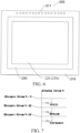
- a microdisplay including:
- the drive circuit is integrated into the backplane; and corresponding to any pixel unit, the drive circuit includes at least one anode, and each of the at least one anode electrical connection structure is electrically connected to the corresponding anode.
- the microdisplay further includes an insulation layer and a transparent conductive layer attached to a surface of the display region in sequence from inside to outside, and the transparent conductive layer is connected to the peripheral common cathode; and the insulation layer is provided with at least one hollow, and the cathode electrical connection structure is connected to the transparent conductive layer through the hollow of the insulation layer.
- a discrete device including:
- the pixel unit includes a backplane, a display unit, a cathode electrical connection structure, and at least one anode electrical connection structure, where the display unit is arranged on the backplane, and the cathode electrical connection structure and the at least one anode electrical connection structure are respectively embedded in the display unit from a side surface away from the backplane;
- the display unit includes at least one device layer, the at least one device layer is vertically stacked in sequence, each of the at least one device layer includes a P-type contact layer, a pixel layer, and an N-type contact layer stacked in sequence, and the P-type contact layer is located on a side of the device layer facing the backplane; and each of the at least one anode electrical connection structure is electrically connected to the P-type contact layer of the corresponding device layer, and the cathode electrical connection structure is electrically connected to the N-type contact layer of each of the
- the pixel unit provided in this application at least two device layers are vertically stacked and integrated in sequence on the backplane, to realize colored display.
- the pixel unit in this application occupies smaller space in the horizontal direction, so that ultra-high-density colored Micro-LED display is realized, thereby realizing a smaller display size at the same resolution or higher resolution at the same screen size.
- a plurality of device layers in a vertical direction share a same negative electrical connection structure, so that an area proportion of a light-emitting region is improved, thereby reducing impact of a size effect.
- a first anode electrical connection structure includes a first partial structure and a second partial structure connected in sequence, and an area of an end surface of the second partial structure is larger than an area of an end surface of the first partial structure, to form a first flange at a joint between the first partial structure and the second partial structure; and the pixel unit further includes a passivation layer, the passivation layer is partially attached to outer surfaces of the display unit and the backplane, the passivation layer is partially attached between the at least one anode electrical connection structure and the display unit, and the passivation layer is partially attached between the cathode electrical connection structure and the display unit.
- a flange structure is constructed through a diameter change, to realize an electrical connection between the anode electrical connection structure and the P-type contact layer or between the cathode electrical connection structure and the N-type contact layer, thereby simplifying the structure, and reducing process difficulty.
- this application provides a method for manufacturing a pixel unit.
- the manufacturing method includes: preparing a backplane; vertically stacking at least one device layer in sequence on the backplane to form a display unit, where each of the at least one device layer includes a P-type contact layer, a pixel layer, and an N-type contact layer stacked in sequence, and the P-type contact layer is located on a side of the device layer facing the backplane; performing etching inwardly from a side surface of the display unit away from the backplane to construct a cathode electrical connection channel and at least one anode electrical connection channel; and performing metal filling on the cathode electrical connection channel and the at least one anode electrical connection channel to form a cathode electrical connection structure and at least one anode electrical connection structure, where the cathode electrical connection structure is electrically connected to the N-type contact layer of each of the at least one device layer respectively, and each of the at least one anode electrical connection structure is electrically connected to the P-
- a solution of stacking first and then patterning is used, which avoids, by using a semiconductor process, high costs of aligned bonding, avoids an alignment precision deviation, and realizes stacking of pixels of smaller sizes in a process, thereby reducing process difficulty, and saving process costs.
- orientation or position relationships indicated by the terms such as “upper”, “lower”, “inner”, and “outer” are based on orientation or position relationships shown in the accompanying drawings, and are used only for ease and brevity of illustration and description of this application, rather than indicating or implying that the mentioned apparatus or component needs to have a particular orientation or needs to be constructed and operated in a particular orientation. Therefore, such terms should not be construed as limiting of this application.
- first and “second” are used for descriptive purposes only and are not to be construed as indicating or implying relative importance or implicitly indicating the number of technical features indicated. Therefore, a feature defined by “first” or “second” may explicitly or implicitly include one or more features.
- a plurality of means two or more than two.
- connection may be a fixed connection, a detachable connection, or an integral connection; or the connection may be a mechanical connection or an electrical connection; or the connection may be a direct connection, an indirect connection through an intermediary, or internal communication between two components.
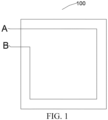
- this embodiment provides a pixel unit 100.
- the pixel unit may be used as a minimum light-emitting unit of a discrete device 300 shown in FIG. 3 to FIG. 5 , or may be used as a minimum light-emitting unit of a microdisplay 200 shown in FIG. 6 .
- the pixel unit 100 includes a backplane 10, a display unit 20, a cathode electrical connection structure 30, and at least one anode electrical connection structure.
- the display unit 20 is arranged on the backplane 10, and the cathode electrical connection structure 30 and the at least one anode electrical connection structure are respectively embedded in the display unit 20 from a side surface away from the backplane 10.
- Each of the at least one anode electrical connection structure is connected to the backplane 10.
- the display unit 20 includes at least one device layer, and the at least one device layer is vertically stacked in sequence in a direction perpendicular to the backplane 10, to form a wafer level vertical stack pixel (WLVSP).
- Each of the at least one device layer includes a P-type contact layer, a pixel layer, and an N-type contact layer stacked in sequence, and the P-type contact layer is located on a side of the device layer facing the backplane 10.
- Each of the at least one anode electrical connection structure is electrically connected to the P-type contact layer of the corresponding device layer, and the cathode electrical connection structure is electrically connected to the N-type contact layer of each of the at least one device layer respectively. Therefore, preferably, a quantity of anode electrical connection structures included in the pixel unit in this embodiment corresponds to a quantity of device layers.
- a quantity of device layers included in the display unit 20 is not limited in this embodiment, and may be one, two, three, or even more.
- the quantity of device layers is not less than two, light-emitting compound epitaxial layers respectively included in any two device layers may be the same or different.
- the light-emitting compound epitaxial layers included in the any two device layers are the same, brightness improvement of a light source of a same color is realized, or a spare redundant device layer is formed to improve the yield of the pixel unit.
- colored display for example, full colored display such as display of pixels of three primary colors: red, green, and blue, is realized.
- the display unit 20 includes a first device layer 40 that emits red light, a second device layer 50 that emits green light, and a third device layer 60 that emits blue light.
- each of the at least one device layer in this embodiment may be of a common pattern such as a quadrilateral, a hexagon, an octagon, or a circle, or a combination of patterns. This is not further limited in this embodiment.
- the backplane 10 is a passive backplane or an active backplane into which a drive circuit is integrated.
- the backplane 10 is preferably an active backplane.
- a drive circuit is provided with at least one anode, and an active drive backplane and a semi-active drive backplane including one or more of a thin film transistor (TFT), low-temperature polysilicon (LTPS), a CMOS integrated circuit, or a high electron mobility transistor (HEMT).
- TFT thin film transistor
- LTPS low-temperature polysilicon
- CMOS integrated circuit a high electron mobility transistor
- HEMT high electron mobility transistor
- FIG. 8 and FIG. 9 respectively show that two red-emitting device layers are stacked first and then a green-emitting device layer and a blue-emitting device layer are stacked, where the two red-emitting device layers may be connected in parallel or series.
- a circuit of each device layer may include an active, a passive, or a semi-passive control circuit.
- An exemplary circuit is shown in FIG. 10 . It should be noted that, the circuit diagram in this embodiment is only a simple schematic diagram. The at least one anode in this embodiment may be arranged on a same straight line, arranged in a triangularly stacked form, or arranged in an array form. Any anode is located in the middle or at an edge of the drive backplane 10.
- the backplane is preferably a passive backplane.
- the backplane is preferably made of materials such as a PCB, sapphire, glass, and Si.
- the passive backplane is connected to a power supply by using a downstream encapsulation process.
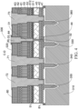
- the first device layer 40 includes a first bonding layer 41, a first P-type contact layer 42, a first pixel layer 43, and a first N-type contact layer 44 stacked in sequence, and the first P-type contact layer 42 is located on a side of the first device layer 40 close to the backplane 10;
- the second device layer 50 is stacked on a side surface of the first device layer 40 away from the backplane 10, the second device layer 50 includes a second bonding layer 51, a second P-type contact layer 52, a second pixel layer 53, and a second N-type contact layer 54 stacked in sequence, and the second bonding layer 51 is connected to the first pixel layer 43;
- the third device layer 60 is stacked on a side surface of the second device layer 50 away from the first device layer 40, the third device layer 60 includes a third bonding layer 61, a third P-type contact layer 62, a third pixel layer 63, and a third N-type contact layer 64 stacked in
- both the second bonding layer 51 and the third bonding layer 61 are made of transparent bonding materials, to facilitate penetration of light.
- the transparent bonding material may be a transparent dielectric, for example, an organic transparent dielectric such as SU8; or an inorganic transparent dielectric such as SiO 2 , Si 3 N 4 , or sapphire; or a semiconductive transparent material such as ITO, GaAs, GaP, or GaN.
- any of the foregoing P-type contact layers includes Ohmic contact and Schottky contact; may be made of a transparent conductive material such as ITO, or may be made of a stack or an alloy of a metal material such as Au, Ni, Ag, Mg, Be, or Zn; and is preferably made of ITO.
- the N-type contact layer is made of a stack and an alloy of one or more of Cr, Al, Ni, Ti, Au, Ge, Au, ITO, or ZnO, for example, AuGeNiAu.
- any P-type contact layer is formed by coating ITO on a first compound semiconductor wafer through evaporation, sputtering, or the like.
- a thickness of the ITO film is 500 nm
- the Ohmic contact is formed by high-temperature annealing at 500°C in an N 2 environment.
- surface roughening treatment is performed on a surface of the N-type contact layer, including randomly or regularly distributed structures such as pits and tapers.
- the first pixel layer 43 is an AlGaInP or InGaN red-emitting compound epitaxial layer
- the second pixel layer 53 is an InGaN green-emitting compound epitaxial layer
- the third pixel layer 63 is an InGaN blue-emitting compound epitaxy epitaxial layer.
- the second bonding layer 51 includes a functional layer 511 and a second bonding layer body 512, and the functional layer 511 is arranged between the second bonding layer body 512 and the first pixel layer 43.
- the functional layer 511 is at least one of an optical sieve, a Bragg reflection layer, an ODR structure, or a contact electrode.
- the functional layer is a filter material, is arranged on the first N-type contact layer 44, and may be an organic colored glue or a stack of inorganic silicon oxide and titanium oxide thin films.
- the functional layer has a characteristic of allowing only red light wavelengths to pass through.
- the pixel unit 100 further includes a first anode electrical connection structure 71, a second anode electrical connection structure 72, and a third anode electrical connection structure 73, and all the three anode electrical connection structures are connected to the backplane 10 and are electrically connected to the P-type contact layers of the corresponding device layers.
- the first anode electrical connection structure 71 is electrically connected to the first P-type contact layer 42
- the second anode electrical connection structure 72 is electrically connected to the second P-type contact layer 52
- the third anode electrical connection structure 73 is electrically connected to the third P-type contact layer 62.
- the first anode electrical connection structure 71 includes a first partial structure 711 and a second partial structure 712 connected in sequence.
- the first partial structure 711 is embedded in the first bonding layer 41 and the first P-type contact layer 42, and an end of the first partial structure 711 is connected to the backplane 10.
- the second partial structure 712 is partially embedded in the first pixel layer 43, and the second partial structure 712 is electrically connected to the first P-type contact layer 42.
- An area of an end surface of the second partial structure 712 is larger than an area of an end surface of the first partial structure 711, to form a first flange 713 at a joint between the first partial structure 711 and the second partial structure 712; and the first flange 713 is connected to the first P-type contact layer 42.
- a flange structure may also be formed at a joint between the first anode electrical connection structure 71 and the second P-type contact layer 52 or the third P-type contact layer 62, to improve structural stability between the first anode electrical connection structure 71 and each device layer.
- any two flanges arranged in anode electrical connection structures may be electrically connected to corresponding P-type contact layers respectively.
- the second anode electrical connection structure 72 includes a second flange 721, and the second flange 721 is electrically connected to the second P-type contact layer 52; and the third anode electrical connection structure 73 includes a third flange 731, and the third flange 731 is electrically connected to the third P-type contact layer 62.
- the first N-type contact layer 44, the second N-type contact layer 54, and the third N-type contact layer 64 each are of a protruding structure, the first N-type contact layer 44 is embedded in the second bonding layer 51, and the second N-type contact layer 54 is embedded in the third bonding layer 61.
- the first N-type contact layer 44, the second N-type contact layer 54, and the third N-type contact layer 64 are located in a vertical direction of the same backplane 10.
- the third N-type contact layer 64 is located directly above the second N-type contact layer 54, and the second N-type contact layer 54 is located directly above the first N-type contact layer 44, to facilitate construction of the cathode electrical connection structure, and reduce process difficulty.
- projections of the first N-type contact layer 44, the second N-type contact layer 54, and the third N-type contact layer 64 on the backplane 10 are semicircles with a same center, and radii of the semicircles increase from the first N-type contact layer 44 to the third N-type contact layer 64.
- the cathode electrical connection structure 30 includes a third partial structure 31, the third partial structure 31 is embedded in the second device layer 72, and an end of the third partial structure 31 is connected to the first N-type contact layer.
- the backplane 10 is not provided with a cathode, and the cathode is arranged on a periphery or a surface of the display unit.
- the cathode electrical connection structure 30 further includes a fourth partial structure 32, one end of the fourth partial structure 32 is connected to the backplane 10, and an other end of the fourth partial structure 32 passes through the first device layer 71 and is connected to the third partial structure 31.
- the fourth partial structure 32 is in an insulated state from the backplane 10 and the first device layer 71.
- the fourth partial structure 32 is insulated from only the first device layer 71.
- the cathode electrical connection structure 30 further includes a fifth partial structure 33 connected to the third partial structure 31, and the fifth partial structure 33 is embedded in the third device layer 60; an area of an end surface of the fifth partial structure 33 is larger than an area of an end surface of the third partial structure 31, to form a fourth flange 34 at a joint between the fifth partial structure 33 and the third partial structure 31; and the fourth flange 4 is connected to the second N-type contact layer 54.
- the pixel unit 100 further includes a passivation layer 80.
- the passivation layer 80 is made of a transparent insulation material.
- the passivation layer 80 is partially attached to outer surfaces of the display unit 20 and the backplane 10, the passivation layer 80 is partially attached between the at least one anode electrical connection structure and the display unit 20, and the passivation layer 80 is partially attached between the cathode electrical connection structure 30 and the display unit 20.
- the passivation layer 80 is provided with at least one through hole, the at least one through hole is provided between each of the at least one anode electrical connection structure and the corresponding P-type contact layer, and the at least one through hole is provided between the cathode electrical connection structure 30 and the corresponding N-type contact layer.
- this embodiment further provides a method for manufacturing a pixel unit.
- the method includes the following steps.
- S2 Vertically stack at least one device layer in sequence on the backplane to form a display unit.
- Each of the at least one device layer includes a P-type contact layer, a pixel layer, and an N-type contact layer stacked in sequence, and the P-type contact layer is located on a side of the device layer facing the backplane.
- the at least one device layer includes the first device layer, and the at least one device layer includes the first device layer.
- the vertically stacking at least one device layer in sequence on the backplane to form a display unit includes the following steps.
- S11 Plate a bonding material on a surface of the backplane and a surface of a P-type contact layer of a prepared first compound semiconductor wafer respectively and perform bonding to form a first bonding layer.
- S12 Remove a substrate of the first compound semiconductor wafer and perform compound semiconductor thinning to expose a first N-type contact layer, where the first N-type contact layer is of a protruding structure.
- the at least one device layer further includes a second device layer and a third device layer.
- the first compound semiconductor wafer has completed P-type Ohmic contact.
- the bonding material is preferably SiO 2 , and SiO 2 -SiO 2 bonding is implemented.
- a silicon oxide film with a flat surface is coated on the first compound semiconductor wafer that has completed the P-type Ohmic contact, where the silicon oxide film has a silicon oxide surface roughness Ra less than 7 nm and a film thickness of 10 nm to 10000 nm.
- a Si layer of 1 to 15 nm may be coated on the surface.
- step S1 further includes the following step.
- S13 Vertically stack the second device layer and the third device layer in sequence on a side surface of the first device layer away from the backplane, to form the display unit. Certainly, stacking manners of the second device layer and the third device layer are consistent with that of the first bonding layer. Details are not described herein again.
- the first compound semiconductor wafer red-emitting epitaxial wafer
- a second compound semiconductor wafer green-emitting epitaxial wafer
- a third compound semiconductor wafer blue-emitting epitaxial wafer
- a compound of the first compound semiconductor wafer belongs to an AlGaInP red-emitting system
- the substrate of the first compound semiconductor wafer is preferably N-GaAs
- a structure of the first compound semiconductor wafer is shown in Table 1 below.
- Table 1 Layer name Material P contact P-GaAs MQW AlGaInP N contact N-AlGaInP Etch Stop N-AlGaInP Substrate N-GaAs
- S3 Perform etching inwardly from a side surface of the display unit away from the backplane to construct a cathode electrical connection channel and at least one anode electrical connection channel.
- step S3 includes following steps.
- S31 Perform, through patterned dry etching, preliminary deep etching layer by layer from the side surface of the display unit away from the backplane to the inside.
- S32 Perform, through patterned wet etching, deep etching on the display unit having been subjected to the preliminary deep etching, until the backplane is exposed to form the at least one anode electrical connection channel, and until the corresponding N-type contact layer is exposed to form the cathode electrical connection channel.
- S33 Perform, through patterned wet etching, deep etching on the display unit having been subjected to the preliminary deep etching, until the backplane is exposed to form the cathode electrical connection channel and the at least one anode electrical connection channel.
- step S32 is performed.
- the backplane is provided with a cathode pad.
- step S33 is performed.
- the cathode electrical connection channel extends to the backplane, to facilitate a connection between a subsequently constructed cathode electrical connection structure and the cathode pad.
- S4 Perform metal filling on the cathode electrical connection channel and the at least one anode electrical connection channel to form a cathode electrical connection structure and at least one anode electrical connection structure.
- the cathode electrical connection structure is electrically connected to the N-type contact layer of each of the at least one device layer respectively, and each of the at least one anode electrical connection structure is electrically connected to the P-type contact layer of the corresponding device layer.
- step S4 includes the following steps.
- step S41 Passivate outer surfaces of the display unit and the backplane and inner walls of the cathode electrical connection channel and the at least one anode electrical connection channel to form a passivation layer, and provide at least one through hole through patterned etching, where the at least one through hole is provided between each of the at least one anode electrical connection structure and the corresponding P-type contact layer, and the at least one through hole is provided between the cathode electrical connection structure and the corresponding N-type contact layer.
- the passivation layer on the surface of the backplane corresponding to the cathode electrical connection channel is provided with a through hole.
- S42 Perform metal filling on the cathode electrical connection channel and the at least one anode electrical connection channel through sputtering, electroplating, chemical plating, or evaporation, to construct the cathode electrical connection structure and the at least one anode electrical connection structure.
- the pixel unit includes a backplane, a display unit, a cathode electrical connection structure, and at least one anode electrical connection structure, where the display unit is arranged on the backplane, and the cathode electrical connection structure and the at least one anode electrical connection structure are respectively embedded in the display unit from a side surface away from the backplane;
- the display unit includes at least one device layer, the at least one device layer is vertically stacked in sequence, each of the at least one device layer includes a P-type contact layer, a pixel layer, and an N-type contact layer stacked in sequence, and the P-type contact layer is located on a side of the device layer facing the backplane; and each of the at least one anode electrical connection structure is electrically connected to the P-type contact layer of the corresponding device layer, and the cathode electrical connection structure is electrically connected to the N-type contact layer of
- the pixel unit provided in this embodiment at least two device layers are vertically stacked and integrated in sequence on the backplane, to realize colored display.
- the pixel unit in this embodiment occupies smaller space in the horizontal direction, so that ultra-high-density colored Micro-LED display is realized, thereby realizing a smaller display size at the same resolution or higher resolution at the same screen size.
- a plurality of device layers in a vertical direction share a same negative electrical connection structure, so that an area proportion of a light-emitting region is improved, thereby reducing impact of a size effect.
- a first anode electrical connection structure includes a first partial structure and a second partial structure connected in sequence, and an area of an end surface of the second partial structure is larger than an area of an end surface of the first partial structure, to form a first flange at a joint between the first partial structure and the second partial structure; and the pixel unit further includes a passivation layer, the passivation layer is partially attached to outer surfaces of the display unit and the backplane, the passivation layer is partially attached between the at least one anode electrical connection structure and the display unit, and the passivation layer is partially attached between the cathode electrical connection structure and the display unit.
- a flange structure is constructed through a diameter change, to realize an electrical connection between the anode electrical connection structure and the P-type contact layer or between the cathode electrical connection structure and the N-type contact layer, thereby simplifying the structure, and reducing process difficulty.
- this embodiment provides a method for manufacturing a pixel unit.
- the manufacturing method includes: preparing a backplane; vertically stacking at least one device layer in sequence on the backplane to form a display unit, where each of the at least one device layer includes a P-type contact layer, a pixel layer, and an N-type contact layer stacked in sequence, and the P-type contact layer is located on a side of the device layer facing the backplane; performing etching inwardly from a side surface of the display unit away from the backplane to construct a cathode electrical connection channel and at least one anode electrical connection channel; and performing metal filling on the cathode electrical connection channel and the at least one anode electrical connection channel to form a cathode electrical connection structure and at least one anode electrical connection structure, where the cathode electrical connection structure is electrically connected to the N-type contact layer of each of the at least one device layer respectively, and each of the at least one anode electrical connection structure is electrically connected to the P-
- a solution of stacking first and then patterning is used, which avoids, by using a semiconductor process, high costs of aligned bonding, avoids an alignment precision deviation, and realizes stacking of pixels of smaller sizes in a process, thereby reducing process difficulty, and saving process costs.
- this embodiment further provides a microdisplay 200.
- the microdisplay 200 includes:
- the construction of the cathode electrode is implemented by arranging the transparent conductive layer, which simplifies an etching step in the pixel unit and also avoids impact on a device layer in an etching process, thereby effectively improving the yields of the pixel unit and the microdisplay.
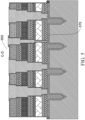
- this embodiment further provides a discrete device 300.
- the discrete device 300 includes:
- the at least one anode pad includes a first anode pad 340 connected to the first device layer 40, a second anode pad 350 connected to the second device layer 50, and a third anode pad 360 connected to the third device layer 60.
- the device body 320 is arranged separately from the discrete device backplane 310, and the at least two pads are arranged separately from the discrete device backplane 310.
- the passivation layer 81 includes a fixing portion 81 or the fixing portion 81, where the fixing portion 81 is connected to the discrete device backplane 310, to connect the device body 320 to the discrete device backplane 310.
- the preferred manner is implemented by pre-arranging a sacrificial layer 370 between the discrete device backplane 310 and the device body 320 and between the discrete device backplane 310 and at least one pad, and then removing the sacrificial layer 370.
- this embodiment further provides a method for manufacturing a discrete device.
- the method includes the following steps.
- S10 Prepare a discrete device backplane. Specifically, S10 includes the following steps.
- S101 Perform etching to form at least four cavities on the prepared discrete device backplane.
- S102 Plate a sacrificial layer on the discrete device backplane provided with the at least four cavities.
- the sacrificial layer is formed by performing coating, thermal oxidation, wet oxidation, or the like on a surface of the discrete device backplane by using a silicon oxynitride film.
- S103 Construct at least four pads on a side of the discrete device backplane coated with the sacrificial layer, where each pad is partially embedded in the corresponding cavity, and the at least four pads include one cathode pad and at least three anode pads.
- the pad in this embodiment is a metal pad, and may be an alloy or a stack of one or more of gold, titanium, tungsten, aluminum, or platinum.
- a preparation manner of the pad includes thermal evaporation, sputtering, electroplating, chemical plating, or the like.
- the pad may be solid or hollow.
- S20 Vertically stack at least one device layer in sequence on the discrete device backplane to form a display unit and construct a cathode electrical connection structure and at least one anode electrical connection structure.
- Step S20 includes the following steps.
- S201 Perform, through patterned dry etching, preliminary deep etching layer by layer from the side surface of the display unit away from the discrete device backplane to the inside.
- S202 Perform, through patterned wet etching, deep etching on the display unit having been subjected to the preliminary deep etching, until the discrete device backplane is exposed to form a cathode electrical connection channel and at least one anode electrical connection channel.
- S203 Passivate outer surfaces of the device body and the discrete device backplane and inner walls of the cathode electrical connection channel and the at least one anode electrical connection channel to form a passivation layer, and provide at least one through hole through patterned etching, where the at least one through hole is provided between each of the at least one anode electrical connection structure and a corresponding P-type contact layer, and the at least one through hole is provided between the cathode electrical connection structure and the discrete device backplane.
- the discrete device backplane is partially covered by the passivation layer.
- a fixing portion is formed at a joint between the device body and the discrete device backplane on the passivation layer. The fixing portion realizes a connection between the device body and the discrete device backplane.
- the sacrificial layer is etched on a side surface of the discrete device backplane on which the passivation layer is not coated, to separate the at least four pads from the discrete device backplane; and an etching rate ratio of the sacrificial layer to the discrete device backplane is greater than 10:1, and an etching rate ratio of the sacrificial layer to the passivation layer is greater than 10:1.
- a gap between the discrete device backplane and the device body after etching ranges from 100 nm to 1000 nm, and preferably ranges from 300 nm to 500 nm.
- the discrete device in this embodiment is connected to an external circuit based on at least two pads.
- the device body is arranged separately from the discrete device backplane, and the at least four pads are arranged separately from the discrete device backplane; and the pixel-level discrete device further includes an insulation support structure, and the insulation support structure covers the device body and a part of the discrete device backplane.
- the insulation support structure is arranged in the pixel discrete device, to realize structural stability when the device body is arranged separately from the backplane and convenience during later use.
- the discrete device backplane can be used cyclically under the structure, so that costs are effectively reduced.
Landscapes
- Devices For Indicating Variable Information By Combining Individual Elements (AREA)
- Led Device Packages (AREA)
- Electroluminescent Light Sources (AREA)
Applications Claiming Priority (2)
| Application Number | Priority Date | Filing Date | Title |
|---|---|---|---|
| CN202210812458.1A CN114899298B (zh) | 2022-07-12 | 2022-07-12 | 一种像素单元及其制作方法、微显示屏、分立器件 |
| PCT/CN2022/119546 WO2024011749A1 (zh) | 2022-07-12 | 2022-09-19 | 一种像素单元及其制作方法、微显示屏、分立器件 |
Publications (2)
| Publication Number | Publication Date |
|---|---|
| EP4550430A1 true EP4550430A1 (de) | 2025-05-07 |
| EP4550430A4 EP4550430A4 (de) | 2025-10-01 |
Family
ID=82729227
Family Applications (1)
| Application Number | Title | Priority Date | Filing Date |
|---|---|---|---|
| EP22950860.1A Pending EP4550430A4 (de) | 2022-07-12 | 2022-09-19 | Pixeleinheit und herstellungsverfahren dafür, mikroanzeigeschirm und diskrete vorrichtung |
Country Status (6)
| Country | Link |
|---|---|
| US (1) | US20250151476A1 (de) |
| EP (1) | EP4550430A4 (de) |
| JP (1) | JP2025524616A (de) |
| KR (1) | KR20250053838A (de) |
| CN (1) | CN114899298B (de) |
| WO (2) | WO2024011749A1 (de) |
Families Citing this family (3)
| Publication number | Priority date | Publication date | Assignee | Title |
|---|---|---|---|---|
| CN114899298B (zh) * | 2022-07-12 | 2022-10-25 | 诺视科技(苏州)有限公司 | 一种像素单元及其制作方法、微显示屏、分立器件 |
| CN116130504B (zh) * | 2023-04-13 | 2023-07-04 | 诺视科技(苏州)有限公司 | 像素单元及其制作方法、微显示屏、像素级分立器件 |
| WO2026020867A1 (zh) * | 2024-07-26 | 2026-01-29 | 诺视科技(苏州)有限公司 | 多色微显示芯片及其制备方法 |
Family Cites Families (23)
| Publication number | Priority date | Publication date | Assignee | Title |
|---|---|---|---|---|
| WO1999047969A1 (en) * | 1998-03-19 | 1999-09-23 | Matsushita Electric Industrial Co., Ltd. | Liquid crystal display device and method of manufacturing the same |
| JP2006106673A (ja) * | 2004-05-25 | 2006-04-20 | Victor Co Of Japan Ltd | 表示装置 |
| KR102513080B1 (ko) * | 2016-04-04 | 2023-03-24 | 삼성전자주식회사 | Led 광원 모듈 및 디스플레이 장치 |
| EP4148811A1 (de) | 2017-03-20 | 2023-03-15 | Jade Bird Display (Shang Hai) Limited | Herstellung von halbleiterbauelementen durch stapeln von schichten aus mikro-leds |
| US10892296B2 (en) * | 2017-11-27 | 2021-01-12 | Seoul Viosys Co., Ltd. | Light emitting device having commonly connected LED sub-units |
| US10748881B2 (en) * | 2017-12-05 | 2020-08-18 | Seoul Viosys Co., Ltd. | Light emitting device with LED stack for display and display apparatus having the same |
| US10886327B2 (en) * | 2017-12-14 | 2021-01-05 | Seoul Viosys Co., Ltd. | Light emitting stacked structure and display device having the same |
| CN109148725B (zh) * | 2018-08-30 | 2021-02-26 | 京东方科技集团股份有限公司 | 发光器件、像素单元、像素单元的制备方法和显示装置 |
| TWI816727B (zh) * | 2018-12-26 | 2023-10-01 | 晶元光電股份有限公司 | 發光二極體顯示器 |
| CN110246953B (zh) * | 2019-07-26 | 2023-08-18 | 厦门乾照半导体科技有限公司 | 一种Micro-LED芯片、显示设备及Micro-LED芯片的制作方法 |
| US12176378B2 (en) * | 2019-08-07 | 2024-12-24 | Seoul Viosys Co., Ltd. | LED display panel and led display apparatus having the same |
| CN110783366A (zh) * | 2019-12-05 | 2020-02-11 | 苏州市奥视微科技有限公司 | 一种全彩显示芯片及半导体芯片的制造工艺 |
| EP4082043A1 (de) * | 2019-12-23 | 2022-11-02 | Lumileds LLC | Iii-nitrid-led-arrays mit mehreren wellenlängen |
| KR102756970B1 (ko) * | 2019-12-27 | 2025-01-17 | 엘지디스플레이 주식회사 | Led 표시장치 |
| US11757073B2 (en) * | 2019-12-28 | 2023-09-12 | Seoul Viosys Co., Ltd. | Light emitting device and LED display apparatus having the same |
| EP4162538A4 (de) * | 2020-06-03 | 2024-09-04 | Jade Bird Display (Shanghai) Limited | Systeme und verfahren für eine mehrfarbige led-pixeleinheit mit horizontaler lichtemission |
| US11695102B2 (en) * | 2020-06-19 | 2023-07-04 | Creeled, Inc. | Active electrical elements with light-emitting diodes |
| CN112117356B (zh) * | 2020-08-13 | 2021-09-17 | 厦门大学 | 一种全彩有源寻址Micro-LED芯片结构及其制作方法 |
| KR102788883B1 (ko) * | 2020-10-29 | 2025-04-01 | 삼성전자주식회사 | Led 디스플레이 장치 |
| CN114093905A (zh) * | 2021-11-18 | 2022-02-25 | 安徽熙泰智能科技有限公司 | 一种叠层Micro LED全彩显示器件及其制备方法 |
| CN114725276B (zh) * | 2022-03-14 | 2023-10-03 | 湖南大学 | Micro-LED分立器件 |
| CN114725150B (zh) * | 2022-03-14 | 2023-10-03 | 湖南大学 | Micro-LED器件及微显示屏 |
| CN114899298B (zh) * | 2022-07-12 | 2022-10-25 | 诺视科技(苏州)有限公司 | 一种像素单元及其制作方法、微显示屏、分立器件 |
-
2022
- 2022-07-12 CN CN202210812458.1A patent/CN114899298B/zh active Active
- 2022-09-19 EP EP22950860.1A patent/EP4550430A4/de active Pending
- 2022-09-19 JP JP2025500977A patent/JP2025524616A/ja active Pending
- 2022-09-19 WO PCT/CN2022/119546 patent/WO2024011749A1/zh not_active Ceased
- 2022-09-19 KR KR1020257001246A patent/KR20250053838A/ko active Pending
-
2023
- 2023-06-30 WO PCT/CN2023/104912 patent/WO2024012271A1/zh not_active Ceased
-
2025
- 2025-01-12 US US19/017,751 patent/US20250151476A1/en active Pending
Also Published As
| Publication number | Publication date |
|---|---|
| CN114899298A (zh) | 2022-08-12 |
| JP2025524616A (ja) | 2025-07-30 |
| KR20250053838A (ko) | 2025-04-22 |
| WO2024011749A1 (zh) | 2024-01-18 |
| WO2024012271A1 (zh) | 2024-01-18 |
| EP4550430A4 (de) | 2025-10-01 |
| CN114899298B (zh) | 2022-10-25 |
| US20250151476A1 (en) | 2025-05-08 |
Similar Documents
| Publication | Publication Date | Title |
|---|---|---|
| CN114725150B (zh) | Micro-LED器件及微显示屏 | |
| CN115064528B (zh) | 用于半导体器件的像素单元及其制作方法、微显示屏 | |
| CN110416247B (zh) | 一种显示组件、显示面板及显示装置 | |
| EP4550430A1 (de) | Pixeleinheit und herstellungsverfahren dafür, mikroanzeigeschirm und diskrete vorrichtung | |
| CN114725276B (zh) | Micro-LED分立器件 | |
| CN116130504B (zh) | 像素单元及其制作方法、微显示屏、像素级分立器件 | |
| CN113299803B (zh) | 一种Micro LED芯片单体器件的制备方法、显示模块及显示装置 | |
| US20250113697A1 (en) | Micro-led display chip and method for manufacturing the same | |
| US20230105156A1 (en) | Display panel, display apparatus, and preparation method for display panel | |
| CN114899286B (zh) | 一种像素级分立器件及其制作方法 | |
| CN115332288A (zh) | 一种像素单元及其制作方法、微显示屏、分立器件 | |
| CN112652617A (zh) | 一种Micro-LED新型显示器件的制备方法 | |
| WO2024012274A1 (zh) | 用于半导体器件的像素单元及其制作方法、微显示屏 | |
| WO2024174829A1 (zh) | MicroLED显示器件及其制备方法 | |
| CN116247072A (zh) | 像素单元及其制作方法、微显示屏、像素级分立器件 | |
| CN116404027A (zh) | 一种Micro-LED微显示器及其制备方法 | |
| CN114843317A (zh) | 一种无机-有机led混合彩色显示器件及其制备方法 | |
| US20250151500A1 (en) | Pixel unit, manufacturing method therefor, microdisplay, and pixel-level discrete device | |
| CN114725080B (zh) | 发光单元、显示装置及其制备方法 | |
| CN116153962A (zh) | 像素单元及其制作方法、微显示屏、像素级分立器件 | |
| US20240405184A1 (en) | Pixel unit for semiconductor device and manufacturing method, micro display screen, discrete device | |
| WO2025190296A1 (zh) | 微型发光二极管显示器件及其制备方法 | |
| US20240162402A1 (en) | Display device | |
| US20250098368A1 (en) | Display panel and preparation method thereof | |
| CN119364939A (zh) | 三基色Micro-LED芯片及其制备与巨转方法 |
Legal Events
| Date | Code | Title | Description |
|---|---|---|---|
| STAA | Information on the status of an ep patent application or granted ep patent |
Free format text: STATUS: THE INTERNATIONAL PUBLICATION HAS BEEN MADE |
|
| PUAI | Public reference made under article 153(3) epc to a published international application that has entered the european phase |
Free format text: ORIGINAL CODE: 0009012 |
|
| STAA | Information on the status of an ep patent application or granted ep patent |
Free format text: STATUS: REQUEST FOR EXAMINATION WAS MADE |
|
| 17P | Request for examination filed |
Effective date: 20250130 |
|
| AK | Designated contracting states |
Kind code of ref document: A1 Designated state(s): AL AT BE BG CH CY CZ DE DK EE ES FI FR GB GR HR HU IE IS IT LI LT LU LV MC MK MT NL NO PL PT RO RS SE SI SK SM TR |
|
| REG | Reference to a national code |
Ref country code: DE Ref legal event code: R079 Free format text: PREVIOUS MAIN CLASS: H01L0033620000 Ipc: H10H0029010000 |
|
| A4 | Supplementary search report drawn up and despatched |
Effective date: 20250902 |
|
| RIC1 | Information provided on ipc code assigned before grant |
Ipc: H10H 29/01 20250101AFI20250827BHEP Ipc: H10H 29/49 20250101ALI20250827BHEP Ipc: H10H 29/80 20250101ALI20250827BHEP |
|
| DAV | Request for validation of the european patent (deleted) | ||
| DAX | Request for extension of the european patent (deleted) |