EP4549795A2 - Kupplung mit rotationsbegrenzten segmenten - Google Patents
Kupplung mit rotationsbegrenzten segmenten Download PDFInfo
- Publication number
- EP4549795A2 EP4549795A2 EP25164620.4A EP25164620A EP4549795A2 EP 4549795 A2 EP4549795 A2 EP 4549795A2 EP 25164620 A EP25164620 A EP 25164620A EP 4549795 A2 EP4549795 A2 EP 4549795A2
- Authority
- EP
- European Patent Office
- Prior art keywords
- another
- segments
- lug
- surfaces contact
- tightening
- Prior art date
- Legal status (The legal status is an assumption and is not a legal conclusion. Google has not performed a legal analysis and makes no representation as to the accuracy of the status listed.)
- Pending
Links
Images


Classifications
-
- F—MECHANICAL ENGINEERING; LIGHTING; HEATING; WEAPONS; BLASTING
- F16—ENGINEERING ELEMENTS AND UNITS; GENERAL MEASURES FOR PRODUCING AND MAINTAINING EFFECTIVE FUNCTIONING OF MACHINES OR INSTALLATIONS; THERMAL INSULATION IN GENERAL
- F16L—PIPES; JOINTS OR FITTINGS FOR PIPES; SUPPORTS FOR PIPES, CABLES OR PROTECTIVE TUBING; MEANS FOR THERMAL INSULATION IN GENERAL
- F16L21/00—Joints with sleeve or socket
- F16L21/06—Joints with sleeve or socket with a divided sleeve or ring clamping around the pipe ends
- F16L21/065—Joints with sleeve or socket with a divided sleeve or ring clamping around the pipe ends tightened by tangentially-arranged threaded pins
-
- F—MECHANICAL ENGINEERING; LIGHTING; HEATING; WEAPONS; BLASTING
- F16—ENGINEERING ELEMENTS AND UNITS; GENERAL MEASURES FOR PRODUCING AND MAINTAINING EFFECTIVE FUNCTIONING OF MACHINES OR INSTALLATIONS; THERMAL INSULATION IN GENERAL
- F16L—PIPES; JOINTS OR FITTINGS FOR PIPES; SUPPORTS FOR PIPES, CABLES OR PROTECTIVE TUBING; MEANS FOR THERMAL INSULATION IN GENERAL
- F16L21/00—Joints with sleeve or socket
- F16L21/002—Sleeves or nipples for pipes of the same diameter; Reduction pieces
- F16L21/005—Sleeves or nipples for pipes of the same diameter; Reduction pieces made of elastic material, e.g. partly or completely surrounded by clamping devices
-
- F—MECHANICAL ENGINEERING; LIGHTING; HEATING; WEAPONS; BLASTING
- F16—ENGINEERING ELEMENTS AND UNITS; GENERAL MEASURES FOR PRODUCING AND MAINTAINING EFFECTIVE FUNCTIONING OF MACHINES OR INSTALLATIONS; THERMAL INSULATION IN GENERAL
- F16L—PIPES; JOINTS OR FITTINGS FOR PIPES; SUPPORTS FOR PIPES, CABLES OR PROTECTIVE TUBING; MEANS FOR THERMAL INSULATION IN GENERAL
- F16L23/00—Flanged joints
- F16L23/04—Flanged joints the flanges being connected by members tensioned in the radial plane
- F16L23/08—Flanged joints the flanges being connected by members tensioned in the radial plane connection by tangentially arranged pin and nut
-
- F—MECHANICAL ENGINEERING; LIGHTING; HEATING; WEAPONS; BLASTING
- F16—ENGINEERING ELEMENTS AND UNITS; GENERAL MEASURES FOR PRODUCING AND MAINTAINING EFFECTIVE FUNCTIONING OF MACHINES OR INSTALLATIONS; THERMAL INSULATION IN GENERAL
- F16L—PIPES; JOINTS OR FITTINGS FOR PIPES; SUPPORTS FOR PIPES, CABLES OR PROTECTIVE TUBING; MEANS FOR THERMAL INSULATION IN GENERAL
- F16L2201/00—Special arrangements for pipe couplings
- F16L2201/10—Indicators for correct coupling
-
- F—MECHANICAL ENGINEERING; LIGHTING; HEATING; WEAPONS; BLASTING
- F16—ENGINEERING ELEMENTS AND UNITS; GENERAL MEASURES FOR PRODUCING AND MAINTAINING EFFECTIVE FUNCTIONING OF MACHINES OR INSTALLATIONS; THERMAL INSULATION IN GENERAL
- F16L—PIPES; JOINTS OR FITTINGS FOR PIPES; SUPPORTS FOR PIPES, CABLES OR PROTECTIVE TUBING; MEANS FOR THERMAL INSULATION IN GENERAL
- F16L23/00—Flanged joints
- F16L23/02—Flanged joints the flanges being connected by members tensioned axially
- F16L23/036—Flanged joints the flanges being connected by members tensioned axially characterised by the tensioning members, e.g. specially adapted bolts or C-clamps
Definitions
- This invention relates to mechanical couplings for joining pipe elements.
- the invention concerns a coupling for joining pipe elements in end to end relation.
- the coupling comprises first and second segments attached to one another end to end surrounding a central space for receiving the pipe elements.
- Each segment comprises a first lug extending from a first end thereof and a second lug extending from a second end thereof.
- the first and second lugs of the first segment align respectively with the first and second lugs of the second segment.
- a first adjustable fastener extends between the first lugs and a second adjustable fastener extends between the second lugs.
- Each segment further comprises a first action surface positioned between the central space and the first lug, and a first support surface positioned on the first lug.
- the first fastener is positioned between the first action surface and the first support surface.
- the first action surface and the first support surface are oriented at a first angle transverse to a longitudinal axis of the first fastener.
- a second action surface is positioned between the central space and the second lug, and a second support surface positioned on the second lug.
- the second fastener is positioned between the second action surface and the second support surface.
- the second action surface and the second support surface are oriented at a second angle transverse to a longitudinal axis of the second fastener.
- the second angle has an opposite slope from the first angle.
- At least a first stop surface is positioned on the first lug adjacent to the first support surface.
- the first stop surface is oriented at a third angle having a slope opposite to the first angle.
- At least a second stop surface is positioned on the second lug adjacent to the second support surface.
- the second stop surface is oriented at a fourth angle having a slope opposite to the second angle.
- the first lugs define a first opening surrounding a first axis oriented perpendicularly to the longitudinal axis of the first fastener and positioned between the first action surfaces and the first support surfaces.
- the first opening may extend through the first lugs.
- the second lugs define a second opening surrounding a second axis oriented perpendicularly to the longitudinal axis of the second fastener and positioned between the second action surfaces and the second support surfaces.
- the second opening may extend through the second lugs.
- each one of the first and second adjustable fasteners comprises a nut and bolt.
- each of the segments comprises first and second arcuate projections positioned on opposite sides of the segments. Each of the arcuate projections face the central space. Each of the arcuate projections is engageable within circumferential grooves in the pipe elements when the segments are drawn toward one another by the adjustable fasteners.
- An example embodiment may further comprise a seal positioned within the central space. The seal supports the segments in spaced apart relation sufficient to permit insertion of the pipe elements into the central space without disassembling the coupling.
- the first angle has a slope of 45° and may also have a slope ranging from 30° to 60°.
- the second angle has an equal but opposite slope to the first angle.
- the invention further encompasses a coupling for joining pipe elements in end to end relation.
- An example coupling embodiment comprises first and second segments attached to one another end to end surrounding a central space for receiving the pipe elements.
- Each segment comprises a first lug extending from a first end thereof and a second lug extending from a second end thereof.
- the first and second lugs of the first segment align respectively with the first and second lugs of the second segment.
- a first adjustable fastener extends between the first lugs and a second adjustable fastener extends between the second lugs.
- Each segment further comprises a first action surface positioned between the central space and the first lug, and a first support surface positioned on the first lug. The first fastener is positioned between the first action surface and the first support surface.
- the first action surface is oriented perpendicularly to a longitudinal axis of the first fastener, and the first support surface is oriented at a first angle transverse to the longitudinal axis of the first fastener.
- a second action surface is positioned between the central space and the second lug, and a second support surface is positioned on the second lug.
- the second fastener is positioned between the second action surface and the second support surface.
- the second action surface is oriented perpendicularly to a longitudinal axis of the second fastener, and the second support surface is oriented at a second angle transverse to the longitudinal axis of the second fastener.
- the second angle has an opposite slope from the first angle.
- At least a first stop surface is positioned on the first lug adjacent to the first support surface.
- the first stop surface is oriented at a third angle having a slope opposite to the first angle.
- At least a second stop surface is positioned on the second lug adjacent to the second support surface.
- the second stop surface is oriented at a fourth angle having a slope opposite to the second angle.
- first lugs define a first opening surrounding a first axis oriented perpendicularly to the longitudinal axis of the first fastener and positioned between the first action surfaces and the first support surfaces.
- the first opening may extend through the first lugs.
- second lugs define a second opening surrounding a second axis oriented perpendicularly to the longitudinal axis of the second fastener and positioned between the second action surfaces and the second support surfaces.
- the second opening may extend through the second lugs.
- each one of the first and second adjustable fasteners comprises a nut and bolt.
- each of the segments comprises first and second arcuate projections positioned on opposite sides of the segments.
- Each of the arcuate projections faces the central space.
- Each of the arcuate projections is engageable within circumferential grooves in the pipe elements when the segments are drawn toward one another by the adjustable fasteners.
- An example embodiment may further comprise a seal positioned within the central space.
- the seal supports the segments in spaced apart relation sufficient to permit insertion of the pipe elements into the central space without disassembling the coupling.
- the first angle has a slope of 45° and may have a slope ranging from 30° to 60°.
- the second angle has an equal but opposite slope to the first angle.
- the invention also encompasses a coupling for joining pipe elements in end to end relation.
- the coupling comprises first and second segments attached to one another end to end surrounding a central space for receiving the pipe elements.
- Each segment comprises a first lug extending from a first end thereof.
- the first lug of the first segment aligns with the first lug of the second segment.
- a first adjustable fastener extends between the first lugs.
- Each segment further comprises a second end.
- the second ends of the segments are arranged opposite to the first ends respectively.
- Each second end is connected to a hinge joining the first and second segments to one another.
- the hinge defines a hinge axis oriented perpendicularly to a longitudinal axis of the first fastener.
- the first and second segments are pivotable about the hinge axis.
- each segment further comprises a first action surface positioned between the central space and the first lug, and a first support surface positioned on the first lug.
- the first fastener is positioned between the first action surface and the first support surface.
- the first action surface is oriented perpendicularly to the longitudinal axis of the first fastener, and the first support surface is oriented at a first angle transverse to the longitudinal axis of the first fastener.
- a first stop surface is positioned on the first lug adjacent to the first support surface.
- the first stop surface is oriented at a third angle having a slope opposite to the first angle.
- the first lugs define a first opening surrounding a first axis oriented perpendicularly to the longitudinal axis of the first fastener and positioned between the first action surfaces and the first support surfaces.
- the first opening may extend through the first lugs.
- the first adjustable fastener comprises a nut and bolt.
- each of the segments comprises first and second arcuate projections positioned on opposite sides of the segments.
- Each of the arcuate projections faces the central space.
- Each of the arcuate projections is engageable within circumferential grooves in the pipe elements when the segments are drawn toward one another by the adjustable fastener.
- a coupling according to the invention may further comprise a seal positioned within the central space. The seal supports the segments in spaced apart relation sufficient to permit insertion of the pipe elements into the central space without disassembling the coupling.
- the first angle has a slope of 45° and may have a slope ranging from 30° to 60°.
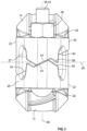
- FIG 1 shows an example coupling 10 according to the invention for joining pipe elements (not shown) in end to end relation.
- the coupling 10 comprises a first segment 12 and a second segment 14.
- Segments 12 and 14 are attached to one another end to end to surround and define a central space 16 for receiving the pipe elements.
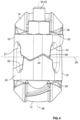
- Coupling 10 is designed to join pipe elements having circumferential grooves at an end and thus each of the segments 12 and 14 comprises first and second arcuate projections 18a and 18b (see also Figure 2 ), also known as "keys", positioned on opposite sides 20 and 22 of the segments 12 and 14.
- the arcuate projections 18a and 18b face the central space 16 and are engageable within circumferential grooves in the pipe elements when the segments are drawn toward one another to form a joint.
- a seal 24 is positioned within the central space 16.
- Seal 24 is advantageously a ring gasket made of an elastomer such as EPDM, and may support the segments 12 and 14 in spaced apart relation as shown, at a distance sufficient to permit insertion of the pipe elements into the central space 16 without disassembling the coupling 10.
- Couplings according to the invention may also be used with plain end pipe, shouldered pipe or other formed pipe ends known in the art.
- each segment 12, 14 comprises a first lug 26 extending from first ends 28 thereof.
- a second lug 30 extends from a second end 32 of each segment.
- the first and second lugs 26 and 30 of the first segment 12 align respectively with the first and second lugs 26 and 30 of the second segment 14.
- a first adjustable fastener 34 extends between the first lugs 26 of each segment 12 and 14, and a second adjustable fastener 36 extends between the second lugs 30 of each segment.
- the first and second adjustable fasteners 34 and 36 comprise a nut 38 and bolt 40.
- Each segment 12 and 14 further comprises a first action surface 42 positioned between the central space 16 and the first lug 26.
- a first support surface 44 is positioned on the first lug 26 of each segment 12 and 14.
- the first fastener 34 is positioned between the first action surfaces 42 and the first support surfaces 44 of the segments 12 and 14.
- the first action surfaces 42 and the first support surfaces 44 are oriented at a first angle 46 transverse to a longitudinal axis 48 of the first fastener 34.
- the first angle 46 may have a slope ranging from 45° to 70°, with a slope of 60° considered advantageous.
- a second action surface 50 is positioned between the central space 16 and the second lug 30 on each segment 12 and 14.
- a second support surface 52 is positioned on the second lugs 30 of each of the segments 12 and 14.
- the second fastener 36 is positioned between the second action surfaces 50 and the second support surfaces 52 of the segments 12 and 14.
- the second action surfaces 50 and the second support surfaces 52 are oriented at a second angle 54 transverse to a longitudinal axis 56 of the second fastener 36.
- the second angles 54 of the second action surfaces 50 and the second support surfaces 52 have an opposite slope from the first angle 46 of the first action surfaces 42 and the first support surfaces 44. It is advantageous if the slopes of the first and second angles 46 and 54 are also equal in magnitude as well as opposite in sign.
- first and second action surfaces 42 and 50 have the same angular orientations as the first and second support surfaces 44 and 52 respectively, a practical design may also advantageously have action surfaces with orientation angles which differ from the orientation angles of their adjacent associated support surfaces.
- At least a first stop surface 58 is positioned on the first lugs 26 of each segment 12 and 14 adjacent to the first support surfaces 44.
- the first stop surfaces 58 are oriented at a third angle 60 (see Figure 1 ) having a slope opposite to the slope of the first angle 46.
- At least a second stop surface 62 is positioned on the second lugs 30 of each segment 12, 14 adjacent to the second support surfaces 52.
- the second stop surfaces 62 are oriented at a fourth angle 64 having a slope opposite to the second angle 54.
- the first lugs 26 may define a first opening 27 surrounding a first axis 29 oriented perpendicularly to the longitudinal axis 48 of the first fastener 34 and positioned between the first action surfaces 42 and the first support surfaces 44.
- the first opening 27 extends through the first lugs 26.
- the bending stiffness of the first lugs 26 may be tuned to a desired value by properly sizing the first opening 27.
- the second lugs 30 may define a second opening 31 surrounding a second axis 33 oriented perpendicularly to the longitudinal axis 56 of the second fastener 36 and positioned between the second action surfaces 50 and the second support surfaces 52.
- the second opening 31 extends through the second lugs 30.
- the bending stiffness of the second lugs 30 may be tuned to a desired value by properly sizing the second opening 31.
- FIGs 1 and 2 show the example coupling 10 in the factory assembled configuration with segments 12 and 14 supported in spaced apart relation on seal 24 at a distance from one another sufficient to permit pipe elements (not shown) to be inserted into the central space 16.
- fasteners 34 and 36 have been tightened sufficiently to hold the segments against the seal.
- the pipe elements are inserted into central space 16 and their circumferential grooves are aligned with the arcuate projections 18a and 18b on opposite sides 20 and 22 of the segments 12 and 14.
- Fasteners 34 and 36 are then further tightened to draw segments 12 and 14 toward one another.
- Figure 3 shows the point when the first and second action surfaces 42 and 50 on segments 12 and 14 engage one another (42 shown).
- support surfaces 44 and 52 on each segment engage at approximately the same time (44 shown).
- Arcuate projections 18a and 18b are also engaged within the grooves of the pipe elements at this point as well.
- engagement of the support surfaces 44 and 52 between the segments 12 and 14 provide a first visual indication confirming that correct installation is proceeding.
- Figure 1 illustrates the axis of rotation 66 of the segments as the pair of action surfaces 42 and the pair of action surfaces 50 on each segment engage one another.
- the object of this rotation is to force the arcuate projections 18a and 18b to securely contact the sidewalls and/or the floors of the circumferential grooves of the pipe elements which they engage and thereby increase the rigidity of the joint in bending, axial loading, and torsion.
- action surfaces 42 and 50 have no feature which limits the degree of relative rotation between the segments 12 and 14 as the fasteners are tightened.
- a feature which limits the relative rotation between the segments 12 and 14 is provided by the respective stop surfaces 58 and 62 on the lugs 26 and 30. As shown in Figure 4 , these stop surfaces (58 shown) engage as the fasteners are further tightened.
- the geometry of the action surfaces 42 and 50, the support surfaces 44 and 52, and the stop surfaces 58 and 62, their lengths, positions on the segments and orientation angles are coordinated with the arcuate projections 18a and 18b such that the projections lock up effectively within the circumferential grooves of the pipe elements when the first stop surfaces 58 and the second stop surfaces 62 respectively engage, or nearly engage as depicted in Figure 4 .
- engagement of both stop surfaces 58 and 62 on opposite ends of the segments 12 and 14 provides visual confirmation that the coupling 10 has been properly installed.
- the stop surface 58 and 62 provide this confirmation over the entire tolerance range imposed on the circumferential grooves in the pipe elements.
- the segments 12 and 14 rotate about axis 66 to the limit imposed by respective engagement between the first stop surfaces 58 and the second stop surfaces 62.
- engagement between one or both projections 18a and 18b and their respective circumferential grooves impose the limit on segment rotation. It is conceivable that when engagement between the projections 18a and 18b and the grooves limits segment relative rotation that one or both of the first and second stop surfaces 58 and 62 will not be engaged.
- the lugs 26 and 30 at opposite ends of the segments 12 and 14 are designed to deform when fasteners 34 and 36 are tightened once the rotational limit imposed by engagement between the projections 18a and 18b and their circumferential grooves is reached to permit the stop surfaces 58 and 62 to engage.
- the deformation is controlled in part by the size of the openings 27 and 29 which extend through the lugs 26 and 30.
- couplings 10 according to the invention are also relatively insensitive to the installation procedure, affording greater ease of assembly. While a preferred installation practice is to partially tighten each fastener in a series of alternating steps, this practice may not always be followed. Instead, a technician may apply a powered impact wrench and fully tighten one fastener and then the other. However, with couplings 10 according to the invention this practice does not result in over-rotation of the coupling segments, which is prevented by engagement of the stop surfaces on the side of the one fastener which is first tightened. The technician may then apply torque to tighten the other fastener to bring the stop surfaces on the opposite end of the coupling into engagement to complete the installation.
- the geometry of the couplings is such that as long as both sets of stop surfaces 58 and 62 are in contact, the projections 18a and 18b will be securely engaged within their respective circumferential grooves, in contact with the groove sidewalls and/or floors to form a rigid joint.
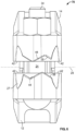
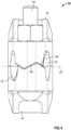
- FIGS 5-8 illustrate another example embodiment of a coupling 70 according to the invention.
- Coupling 70 is identical to coupling 10 as described above except for the orientation of the action surfaces 42 and 50.
- the first action surface 42 is oriented substantially perpendicularly to the longitudinal axis 48 of the first fastener 34 and the second action surface 50 is oriented substantially perpendicularly to the longitudinal axis 56 of said second fastener 36. Due to the different orientation of the action surfaces 42 and 50 the coupling segments 12 and 14 do not rotate about axis 66 upon their engagement when the fasteners 34 and 36 are tightened to bring the segments toward one another to couple pipe elements to one another. Coupling 70 is advantageous when a more flexible pipe joint is desired.
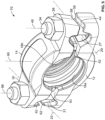
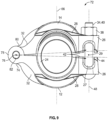
- FIG 9 illustrates another example embodiment of a coupling 72 according to the invention.
- Coupling 72 shares many of the features of coupling embodiments 10 and 70 as described above but substitutes a hinge in place of the second lugs 30.
- the second ends 32 of each segment 12 and 14, arranged opposite to the first ends 28, are connected to a hinge 74 joining the first and second segments to one another.
- the hinge 74 defines a hinge axis 76 oriented perpendicularly to the longitudinal axis 48 of the first fastener 34.
- the first and second segments 12 and 14 are pivotable about the hinge axis 76.
- hinge 74 comprises bearings 78 (shown) and 80 (hidden) rotatably joined by a hinge pin 82.
- Other forms of hinged joints are also practical.
- the first action surfaces 42 of coupling 74 are oriented substantially perpendicularly to the longitudinal axis 48 of the first fastener 34. Due to the perpendicular orientation of the action surfaces 42, the coupling segments 12 and 14 do not rotate relatively to one another about axis 66 upon their engagement when the fastener 34 is tightened to bring the segments toward one another to couple pipe elements to one another. Like coupling 70, coupling 74 is advantageous when a more flexible pipe joint is desired. When the fastener 34 is tightened, friction between the torqued fastener and its respective lug tends to rotate the coupling segments relatively to one another, thereby causing unwanted engagement between the projections 18a and 18b and the grooves in the pipe elements.
- the first lugs 26 of coupling 74 define a first opening 27 surrounding a first axis 29 oriented perpendicularly to the longitudinal axis 48 of the first fastener 34.
- Axis 48 and fastener 34 are positioned between the first action surfaces 42 and the first support surfaces 44.
- the first opening 27 extends through said first lugs 26.
- the first adjustable fastener 34 may comprise a nut 38 and bolt 40.
Landscapes
- Engineering & Computer Science (AREA)
- General Engineering & Computer Science (AREA)
- Mechanical Engineering (AREA)
- Mutual Connection Of Rods And Tubes (AREA)
- Clamps And Clips (AREA)
- Supports For Pipes And Cables (AREA)
- Joints Allowing Movement (AREA)
- Radiation-Therapy Devices (AREA)
- Electrotherapy Devices (AREA)
- Joints With Pressure Members (AREA)
- Joining Of Building Structures In Genera (AREA)
- Joints With Sleeves (AREA)
- Flanged Joints, Insulating Joints, And Other Joints (AREA)
Applications Claiming Priority (3)
| Application Number | Priority Date | Filing Date | Title |
|---|---|---|---|
| US202063110433P | 2020-11-06 | 2020-11-06 | |
| EP21889846.8A EP4241007A4 (de) | 2020-11-06 | 2021-10-26 | Kupplung mit rotationsbegrenzten segmenten |
| PCT/US2021/056560 WO2022098534A1 (en) | 2020-11-06 | 2021-10-26 | Coupling having rotation limited segments |
Related Parent Applications (1)
| Application Number | Title | Priority Date | Filing Date |
|---|---|---|---|
| EP21889846.8A Division EP4241007A4 (de) | 2020-11-06 | 2021-10-26 | Kupplung mit rotationsbegrenzten segmenten |
Publications (2)
| Publication Number | Publication Date |
|---|---|
| EP4549795A2 true EP4549795A2 (de) | 2025-05-07 |
| EP4549795A3 EP4549795A3 (de) | 2025-07-02 |
Family
ID=81453343
Family Applications (3)
| Application Number | Title | Priority Date | Filing Date |
|---|---|---|---|
| EP21889846.8A Pending EP4241007A4 (de) | 2020-11-06 | 2021-10-26 | Kupplung mit rotationsbegrenzten segmenten |
| EP25211890.6A Pending EP4660506A2 (de) | 2020-11-06 | 2021-10-26 | Kupplung mit rotationsbegrenzten segmenten |
| EP25164620.4A Pending EP4549795A3 (de) | 2020-11-06 | 2021-10-26 | Kupplung mit rotationsbegrenzten segmenten |
Family Applications Before (2)
| Application Number | Title | Priority Date | Filing Date |
|---|---|---|---|
| EP21889846.8A Pending EP4241007A4 (de) | 2020-11-06 | 2021-10-26 | Kupplung mit rotationsbegrenzten segmenten |
| EP25211890.6A Pending EP4660506A2 (de) | 2020-11-06 | 2021-10-26 | Kupplung mit rotationsbegrenzten segmenten |
Country Status (13)
| Country | Link |
|---|---|
| US (3) | US11624461B2 (de) |
| EP (3) | EP4241007A4 (de) |
| JP (2) | JP7609989B2 (de) |
| KR (3) | KR20250150678A (de) |
| CN (1) | CN116867978A (de) |
| AU (2) | AU2021373574B2 (de) |
| CA (1) | CA3197242C (de) |
| IL (1) | IL302432A (de) |
| MX (1) | MX2023005307A (de) |
| NZ (1) | NZ799707A (de) |
| PE (1) | PE20232058A1 (de) |
| TW (1) | TWI786923B (de) |
| WO (1) | WO2022098534A1 (de) |
Families Citing this family (11)
| Publication number | Priority date | Publication date | Assignee | Title |
|---|---|---|---|---|
| USD897195S1 (en) * | 2019-02-28 | 2020-09-29 | Victaulic Company | Ring and gusset coupling |
| USD1053319S1 (en) * | 2020-11-13 | 2024-12-03 | Victaulic Company | Pipe coupling |
| USD1021015S1 (en) * | 2020-11-13 | 2024-04-02 | Victaulic Company | Pipe coupling |
| USD1043925S1 (en) * | 2020-11-13 | 2024-09-24 | Victaulic Company | Pipe coupling segment |
| USD1083579S1 (en) * | 2021-01-20 | 2025-07-15 | Ubicquia, Inc. | Camera system |
| USD1002358S1 (en) * | 2021-01-20 | 2023-10-24 | Ubicquia, Inc. | Pole clamp |
| US20230158350A1 (en) * | 2021-11-19 | 2023-05-25 | Minimax Viking Research & Development Gmbh | Protected Branch Connector Assembly For Fire Protection Systems |
| KR102712269B1 (ko) * | 2023-04-20 | 2024-10-04 | 주식회사 하이스텐 | 플랜지에 체결면이 형성되는 배관용 클램프 |
| KR20250021706A (ko) * | 2023-08-07 | 2025-02-14 | 주식회사 하이스텐 | 패킹이 결합되는 배관용 클램프 |
| KR20250026435A (ko) * | 2023-08-17 | 2025-02-25 | 주식회사 하이스텐 | 와셔가 설치되는 관 연결 소켓 |
| WO2025080380A1 (en) * | 2023-10-10 | 2025-04-17 | Victaulic Company | Coupling |
Citations (1)
| Publication number | Priority date | Publication date | Assignee | Title |
|---|---|---|---|---|
| US4639020A (en) | 1983-07-12 | 1987-01-27 | Victaulic Company Of America | Self-adjusting pipe clamp and coupling |
Family Cites Families (30)
| Publication number | Priority date | Publication date | Assignee | Title |
|---|---|---|---|---|
| US2752173A (en) | 1952-06-02 | 1956-06-26 | Victaulic Co Of America | Flexible or rigid joint pipe couplings |
| US4896902A (en) * | 1988-09-29 | 1990-01-30 | Victaulic Company Of America | Segmented transition coupling |
| US5018704A (en) | 1990-01-12 | 1991-05-28 | Victaulic Company Of America | Pipe coupling with in-coupling flow controller |
| US5018768A (en) | 1990-07-19 | 1991-05-28 | Quikcoup, Incorporated | Pipe coupling hinge |
| US5758907A (en) * | 1996-07-26 | 1998-06-02 | Victaulic Company Of America | Mis-adjustment limiting segmented pipe coupling |
| US6533333B1 (en) | 1998-08-24 | 2003-03-18 | Central Sprinkler Corporation | Hinged mechanical couplings with interfitting ends |
| JP3781681B2 (ja) * | 2002-01-17 | 2006-05-31 | アルパイン株式会社 | ディスク装置 |
| US20030178850A1 (en) * | 2002-03-20 | 2003-09-25 | Dole Douglas R. | Pipe coupling with V-shaped tongue and recess |
| US8267432B2 (en) | 2004-03-26 | 2012-09-18 | Victaulic Company | Coupling having angularly oriented key surfaces |
| WO2005094295A2 (en) * | 2004-03-26 | 2005-10-13 | Victaulic Company Of America | Pipe coupling having keys with camming surfaces |
| US7086131B2 (en) * | 2004-05-14 | 2006-08-08 | Victaulic Company | Deformable mechanical pipe coupling |
| KR100647065B1 (ko) * | 2005-05-19 | 2006-11-23 | 홍성돈 | 파이프 커플링 |
| WO2008008289A2 (en) | 2006-07-13 | 2008-01-17 | Victaulic Company | Coupling assembly having conical interfacing surfaces |
| US7540540B2 (en) | 2007-01-11 | 2009-06-02 | Younwoo Engineering Co., Ltd. | Pipe coupling |
| US7950701B2 (en) | 2007-05-15 | 2011-05-31 | Victaulic Company | Pipe coupling having movable gripping bodies |
| JP5175007B2 (ja) | 2008-07-01 | 2013-04-03 | 株式会社リケン | ハウジング形管継手 |
| US8136847B2 (en) * | 2009-05-14 | 2012-03-20 | Victaulic Company | Coupling having angularly oriented shoulder surfaces |
| JP5315187B2 (ja) * | 2009-09-23 | 2013-10-16 | 株式会社リケン | ハウジング形管継手 |
| AU2010313470B2 (en) | 2009-10-27 | 2016-08-11 | Tyco Fire Products Lp | Systems and methods for hinge couplings |
| US8556302B2 (en) * | 2011-04-05 | 2013-10-15 | Victaulic Company | Pivoting pipe coupling having a movable gripping body |
| US20130125373A1 (en) * | 2011-11-21 | 2013-05-23 | Philip W. Bancroft | Coupling with projections having angularly oriented surface portions |
| US10578234B2 (en) | 2013-05-02 | 2020-03-03 | Victaulic Company | Coupling having arcuate stiffness ribs |
| DE202016000436U1 (de) * | 2016-01-26 | 2016-02-10 | Hs Umformtechnik Gmbh | Rohrkupplung zum Verbinden von zwei röhrenförmigen Körpern |
| DE102016107159B4 (de) | 2016-04-18 | 2021-10-07 | Sartorius Stedim Biotech Gmbh | Anschlussvorrichtung |
| JP6439748B2 (ja) | 2016-05-16 | 2018-12-19 | 株式会社豊田自動織機 | クランプ結合具及びクランプ結合方法 |
| US10859190B2 (en) | 2016-05-16 | 2020-12-08 | Victaulic Company | Sprung coupling |
| US10533688B2 (en) * | 2016-05-16 | 2020-01-14 | Victaulic Company | Coupling having tabbed retainer |
| US11421804B2 (en) | 2019-04-19 | 2022-08-23 | Aalberts integrated piping systems APAC, Inc. | Quick installation coupling |
| EP3969796A4 (de) | 2019-05-14 | 2023-01-11 | Tyco Fire Products LP | Rohrkupplung |
| CN110985778B (zh) * | 2020-01-20 | 2025-06-03 | 潍坊精锐模具设备有限公司 | 一种新型快速沟槽连接器 |
-
2021
- 2021-10-26 EP EP21889846.8A patent/EP4241007A4/de active Pending
- 2021-10-26 MX MX2023005307A patent/MX2023005307A/es unknown
- 2021-10-26 NZ NZ799707A patent/NZ799707A/en unknown
- 2021-10-26 KR KR1020257032565A patent/KR20250150678A/ko active Pending
- 2021-10-26 CN CN202180074542.1A patent/CN116867978A/zh active Pending
- 2021-10-26 AU AU2021373574A patent/AU2021373574B2/en active Active
- 2021-10-26 EP EP25211890.6A patent/EP4660506A2/de active Pending
- 2021-10-26 WO PCT/US2021/056560 patent/WO2022098534A1/en not_active Ceased
- 2021-10-26 KR KR1020257032564A patent/KR20250145140A/ko active Pending
- 2021-10-26 JP JP2023526017A patent/JP7609989B2/ja active Active
- 2021-10-26 KR KR1020237016908A patent/KR102867596B1/ko active Active
- 2021-10-26 US US17/510,865 patent/US11624461B2/en active Active
- 2021-10-26 EP EP25164620.4A patent/EP4549795A3/de active Pending
- 2021-10-26 PE PE2023001558A patent/PE20232058A1/es unknown
- 2021-10-26 CA CA3197242A patent/CA3197242C/en active Active
- 2021-10-26 IL IL302432A patent/IL302432A/en unknown
- 2021-11-03 TW TW110140893A patent/TWI786923B/zh active
-
2023
- 2023-03-10 US US18/119,923 patent/US12297936B2/en active Active
-
2024
- 2024-11-01 JP JP2024192779A patent/JP2025019071A/ja active Pending
-
2025
- 2025-03-05 US US19/070,904 patent/US20250305604A1/en active Pending
- 2025-05-05 AU AU2025203198A patent/AU2025203198A1/en active Pending
Patent Citations (1)
| Publication number | Priority date | Publication date | Assignee | Title |
|---|---|---|---|---|
| US4639020A (en) | 1983-07-12 | 1987-01-27 | Victaulic Company Of America | Self-adjusting pipe clamp and coupling |
Also Published As
| Publication number | Publication date |
|---|---|
| CN116867978A (zh) | 2023-10-10 |
| MX2023005307A (es) | 2023-05-25 |
| AU2021373574A9 (en) | 2025-03-20 |
| AU2021373574A1 (en) | 2023-06-15 |
| EP4660506A2 (de) | 2025-12-10 |
| AU2021373574B2 (en) | 2025-05-08 |
| WO2022098534A1 (en) | 2022-05-12 |
| KR20230086791A (ko) | 2023-06-15 |
| US11624461B2 (en) | 2023-04-11 |
| JP2023548120A (ja) | 2023-11-15 |
| NZ799707A (en) | 2025-10-31 |
| EP4241007A1 (de) | 2023-09-13 |
| TW202223275A (zh) | 2022-06-16 |
| JP7609989B2 (ja) | 2025-01-07 |
| US20230235837A1 (en) | 2023-07-27 |
| KR102867596B1 (ko) | 2025-10-01 |
| AU2025203198A1 (en) | 2025-05-29 |
| EP4549795A3 (de) | 2025-07-02 |
| CA3197242C (en) | 2025-05-20 |
| US12297936B2 (en) | 2025-05-13 |
| TWI786923B (zh) | 2022-12-11 |
| KR20250145140A (ko) | 2025-10-13 |
| KR20250150678A (ko) | 2025-10-20 |
| IL302432A (en) | 2023-06-01 |
| CA3197242A1 (en) | 2022-05-12 |
| JP2025019071A (ja) | 2025-02-06 |
| PE20232058A1 (es) | 2023-12-27 |
| US20220146022A1 (en) | 2022-05-12 |
| US20250305604A1 (en) | 2025-10-02 |
| EP4241007A4 (de) | 2024-09-18 |
Similar Documents
| Publication | Publication Date | Title |
|---|---|---|
| US12297936B2 (en) | Method of installing a pipe coupling | |
| JP5116889B2 (ja) | 一対の管要素の対向端における固定方法 | |
| US7789434B2 (en) | Coupling with concave bearing surface | |
| KR100314121B1 (ko) | 오정렬 제한 체절 관 연결구 | |
| TWI588395B (zh) | 使用具有具傾斜定向表面部分之突出物之聯接器之方法 | |
| US20070164566A1 (en) | Lockwireless coupling assembly | |
| KR20140008321A (ko) | 이동 가능한 파지체를 갖는 피벗형 파이프 커플링 | |
| US20250264171A1 (en) | Coupling Having Visual Installation Indicators | |
| US6527233B2 (en) | Device for clamping a shaft | |
| US20250116358A1 (en) | Coupling | |
| HK1138630A (en) | Coupling with concave bearing surface | |
| HK1187392B (en) | Pivoting pipe coupling having a movable gripping body |
Legal Events
| Date | Code | Title | Description |
|---|---|---|---|
| PUAI | Public reference made under article 153(3) epc to a published international application that has entered the european phase |
Free format text: ORIGINAL CODE: 0009012 |
|
| STAA | Information on the status of an ep patent application or granted ep patent |
Free format text: STATUS: THE APPLICATION HAS BEEN PUBLISHED |
|
| AC | Divisional application: reference to earlier application |
Ref document number: 4241007 Country of ref document: EP Kind code of ref document: P |
|
| AK | Designated contracting states |
Kind code of ref document: A2 Designated state(s): AL AT BE BG CH CY CZ DE DK EE ES FI FR GB GR HR HU IE IS IT LI LT LU LV MC MK MT NL NO PL PT RO RS SE SI SK SM TR |
|
| PUAL | Search report despatched |
Free format text: ORIGINAL CODE: 0009013 |
|
| AK | Designated contracting states |
Kind code of ref document: A3 Designated state(s): AL AT BE BG CH CY CZ DE DK EE ES FI FR GB GR HR HU IE IS IT LI LT LU LV MC MK MT NL NO PL PT RO RS SE SI SK SM TR |
|
| RIC1 | Information provided on ipc code assigned before grant |
Ipc: F16L 23/10 20060101AFI20250526BHEP |