EP4549765A1 - A wheel bearing assembly - Google Patents
A wheel bearing assembly Download PDFInfo
- Publication number
- EP4549765A1 EP4549765A1 EP24210056.8A EP24210056A EP4549765A1 EP 4549765 A1 EP4549765 A1 EP 4549765A1 EP 24210056 A EP24210056 A EP 24210056A EP 4549765 A1 EP4549765 A1 EP 4549765A1
- Authority
- EP
- European Patent Office
- Prior art keywords
- slinger
- gap
- outer ring
- wheel bearing
- interval
- Prior art date
- Legal status (The legal status is an assumption and is not a legal conclusion. Google has not performed a legal analysis and makes no representation as to the accuracy of the status listed.)
- Pending
Links
Images

Classifications
-
- F—MECHANICAL ENGINEERING; LIGHTING; HEATING; WEAPONS; BLASTING
- F16—ENGINEERING ELEMENTS AND UNITS; GENERAL MEASURES FOR PRODUCING AND MAINTAINING EFFECTIVE FUNCTIONING OF MACHINES OR INSTALLATIONS; THERMAL INSULATION IN GENERAL
- F16C—SHAFTS; FLEXIBLE SHAFTS; ELEMENTS OR CRANKSHAFT MECHANISMS; ROTARY BODIES OTHER THAN GEARING ELEMENTS; BEARINGS
- F16C19/00—Bearings with rolling contact, for exclusively rotary movement
- F16C19/02—Bearings with rolling contact, for exclusively rotary movement with bearing balls essentially of the same size in one or more circular rows
- F16C19/14—Bearings with rolling contact, for exclusively rotary movement with bearing balls essentially of the same size in one or more circular rows for both radial and axial load
- F16C19/18—Bearings with rolling contact, for exclusively rotary movement with bearing balls essentially of the same size in one or more circular rows for both radial and axial load with two or more rows of balls
- F16C19/181—Bearings with rolling contact, for exclusively rotary movement with bearing balls essentially of the same size in one or more circular rows for both radial and axial load with two or more rows of balls with angular contact
- F16C19/183—Bearings with rolling contact, for exclusively rotary movement with bearing balls essentially of the same size in one or more circular rows for both radial and axial load with two or more rows of balls with angular contact with two rows at opposite angles
- F16C19/184—Bearings with rolling contact, for exclusively rotary movement with bearing balls essentially of the same size in one or more circular rows for both radial and axial load with two or more rows of balls with angular contact with two rows at opposite angles in O-arrangement
- F16C19/186—Bearings with rolling contact, for exclusively rotary movement with bearing balls essentially of the same size in one or more circular rows for both radial and axial load with two or more rows of balls with angular contact with two rows at opposite angles in O-arrangement with three raceways provided integrally on parts other than race rings, e.g. third generation hubs
-
- B—PERFORMING OPERATIONS; TRANSPORTING
- B60—VEHICLES IN GENERAL
- B60B—VEHICLE WHEELS; CASTORS; AXLES FOR WHEELS OR CASTORS; INCREASING WHEEL ADHESION
- B60B27/00—Hubs
- B60B27/0073—Hubs characterised by sealing means
-
- F—MECHANICAL ENGINEERING; LIGHTING; HEATING; WEAPONS; BLASTING
- F16—ENGINEERING ELEMENTS AND UNITS; GENERAL MEASURES FOR PRODUCING AND MAINTAINING EFFECTIVE FUNCTIONING OF MACHINES OR INSTALLATIONS; THERMAL INSULATION IN GENERAL
- F16C—SHAFTS; FLEXIBLE SHAFTS; ELEMENTS OR CRANKSHAFT MECHANISMS; ROTARY BODIES OTHER THAN GEARING ELEMENTS; BEARINGS
- F16C33/00—Parts of bearings; Special methods for making bearings or parts thereof
- F16C33/72—Sealings
- F16C33/76—Sealings of ball or roller bearings
- F16C33/78—Sealings of ball or roller bearings with a diaphragm, disc, or ring, with or without resilient members
- F16C33/7803—Sealings of ball or roller bearings with a diaphragm, disc, or ring, with or without resilient members suited for particular types of rolling bearings
- F16C33/7806—Sealings of ball or roller bearings with a diaphragm, disc, or ring, with or without resilient members suited for particular types of rolling bearings for spherical roller bearings
-
- F—MECHANICAL ENGINEERING; LIGHTING; HEATING; WEAPONS; BLASTING
- F16—ENGINEERING ELEMENTS AND UNITS; GENERAL MEASURES FOR PRODUCING AND MAINTAINING EFFECTIVE FUNCTIONING OF MACHINES OR INSTALLATIONS; THERMAL INSULATION IN GENERAL
- F16C—SHAFTS; FLEXIBLE SHAFTS; ELEMENTS OR CRANKSHAFT MECHANISMS; ROTARY BODIES OTHER THAN GEARING ELEMENTS; BEARINGS
- F16C33/00—Parts of bearings; Special methods for making bearings or parts thereof
- F16C33/72—Sealings
- F16C33/76—Sealings of ball or roller bearings
- F16C33/78—Sealings of ball or roller bearings with a diaphragm, disc, or ring, with or without resilient members
- F16C33/7816—Details of the sealing or parts thereof, e.g. geometry, material
- F16C33/782—Details of the sealing or parts thereof, e.g. geometry, material of the sealing region
- F16C33/7823—Details of the sealing or parts thereof, e.g. geometry, material of the sealing region of sealing lips
-
- F—MECHANICAL ENGINEERING; LIGHTING; HEATING; WEAPONS; BLASTING
- F16—ENGINEERING ELEMENTS AND UNITS; GENERAL MEASURES FOR PRODUCING AND MAINTAINING EFFECTIVE FUNCTIONING OF MACHINES OR INSTALLATIONS; THERMAL INSULATION IN GENERAL
- F16C—SHAFTS; FLEXIBLE SHAFTS; ELEMENTS OR CRANKSHAFT MECHANISMS; ROTARY BODIES OTHER THAN GEARING ELEMENTS; BEARINGS
- F16C33/00—Parts of bearings; Special methods for making bearings or parts thereof
- F16C33/72—Sealings
- F16C33/76—Sealings of ball or roller bearings
- F16C33/78—Sealings of ball or roller bearings with a diaphragm, disc, or ring, with or without resilient members
- F16C33/7869—Sealings of ball or roller bearings with a diaphragm, disc, or ring, with or without resilient members mounted with a cylindrical portion to the inner surface of the outer race and having a radial portion extending inward
- F16C33/7879—Sealings of ball or roller bearings with a diaphragm, disc, or ring, with or without resilient members mounted with a cylindrical portion to the inner surface of the outer race and having a radial portion extending inward with a further sealing ring
- F16C33/7883—Sealings of ball or roller bearings with a diaphragm, disc, or ring, with or without resilient members mounted with a cylindrical portion to the inner surface of the outer race and having a radial portion extending inward with a further sealing ring mounted to the inner race and of generally L-shape, the two sealing rings defining a sealing with box-shaped cross-section
-
- F—MECHANICAL ENGINEERING; LIGHTING; HEATING; WEAPONS; BLASTING
- F16—ENGINEERING ELEMENTS AND UNITS; GENERAL MEASURES FOR PRODUCING AND MAINTAINING EFFECTIVE FUNCTIONING OF MACHINES OR INSTALLATIONS; THERMAL INSULATION IN GENERAL
- F16C—SHAFTS; FLEXIBLE SHAFTS; ELEMENTS OR CRANKSHAFT MECHANISMS; ROTARY BODIES OTHER THAN GEARING ELEMENTS; BEARINGS
- F16C33/00—Parts of bearings; Special methods for making bearings or parts thereof
- F16C33/72—Sealings
- F16C33/76—Sealings of ball or roller bearings
- F16C33/80—Labyrinth sealings
-
- F—MECHANICAL ENGINEERING; LIGHTING; HEATING; WEAPONS; BLASTING
- F16—ENGINEERING ELEMENTS AND UNITS; GENERAL MEASURES FOR PRODUCING AND MAINTAINING EFFECTIVE FUNCTIONING OF MACHINES OR INSTALLATIONS; THERMAL INSULATION IN GENERAL
- F16C—SHAFTS; FLEXIBLE SHAFTS; ELEMENTS OR CRANKSHAFT MECHANISMS; ROTARY BODIES OTHER THAN GEARING ELEMENTS; BEARINGS
- F16C33/00—Parts of bearings; Special methods for making bearings or parts thereof
- F16C33/72—Sealings
- F16C33/76—Sealings of ball or roller bearings
- F16C33/80—Labyrinth sealings
- F16C33/805—Labyrinth sealings in addition to other sealings, e.g. dirt guards to protect sealings with sealing lips
-
- F—MECHANICAL ENGINEERING; LIGHTING; HEATING; WEAPONS; BLASTING
- F16—ENGINEERING ELEMENTS AND UNITS; GENERAL MEASURES FOR PRODUCING AND MAINTAINING EFFECTIVE FUNCTIONING OF MACHINES OR INSTALLATIONS; THERMAL INSULATION IN GENERAL
- F16C—SHAFTS; FLEXIBLE SHAFTS; ELEMENTS OR CRANKSHAFT MECHANISMS; ROTARY BODIES OTHER THAN GEARING ELEMENTS; BEARINGS
- F16C2326/00—Articles relating to transporting
- F16C2326/01—Parts of vehicles in general
- F16C2326/02—Wheel hubs or castors
Definitions
- the present invention relates to a wheel bearing assembly and, more specifically, to a wheel bearing assembly having excellent sealing performance.
- a bearing is a mechanical component mounted between a rotating element and a non-rotating element to facilitate the rotation of the rotating element.
- various types of bearings such as ball bearings, tapered roller bearings, and needle roller bearings, are in use.
- a wheel bearing as a type of the bearings, supports a wheel, which is the rotating element, to rotate relative to a vehicle body which is the non-rotating element.
- the wheel bearing includes an inner ring (and/or hub) connected to either the wheel or the vehicle body, an outer ring connected to the other, and rolling elements interposed between the outer and inner rings.
- the wheel bearing Since the wheel bearing is fundamentally mounted on the vehicle's wheel, the wheel bearing is exposed to foreign substances such as dust and moisture. When the foreign substances infiltrate the interior of the wheel bearing, they can cause noise and vibration during operation of the wheel bearing and shorten the lifespan of the wheel bearing. Therefore, sealing devices are installed at one or both ends of the wheel bearing to prevent the intrusion of foreign substances.
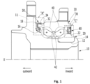
- FIG. 1 is a half cross-sectional view of a conventional wheel bearing assembly.
- the wheel bearing assembly includes a hub 10, an outer ring 30, and rolling elements 40.
- the hub 10 is coupled to the wheel (not illustrated).
- the hub 10 includes a flange 11 to be coupled with the wheel.
- An inner ring 20 is provided on the hub 10.
- the flange 11 can be formed in a disc shape extending in the circumferential direction of the hub 10.
- the outer ring 30 is formed to surround the outer surface of the hub 10, and the outer surface of the hub 10 and the inner surface of the outer ring 30 are spaced apart. Additionally, the outer ring 30 is coupled to the vehicle body (not illustrated).
- the rolling elements 40 are aligned between the track of the hub 10 and the track of the outer ring 30, which are spaced apart from each other. Multiple rolling elements 40 are provided. Furthermore, to facilitate the smooth operation of the wheel bearing, grease can be filled in the space where the rolling elements 40 are interposed.
- reference numeral 42 indicates a cage functioning to maintain a circumferential interval of the rolling elements.
- FIG. 1 illustrates the outer ring 30 connected to the vehicle body (not illustrated) and the hub 10 connected to the wheel (not illustrated), but is not limited thereto.
- the wheel bearing assembly includes sealing devices 50 and 80.
- the sealing devices 50 and 80 prevent foreign substances from entering the space where the rolling elements 40 are interposed, and also prevent the leakage of grease.
- the sealing device 50 provided at an outward opening formed between the hub 10 and the outer ring 30 includes a slinger into which the outer ring 30 adjacent to the hub 10 is press-fitted, and a plurality of lips being in contact with the hub 10 while wrapping around the slinger.
- the outer ring is inserted into the slinger such that an outer circumferential surface 32 and a cross-sectional face 34 of the outer ring is in contact with the slinger.
- Some of the plurality of lips are in contact with a bent part 16 of the hub 10, and others are in contact with a concave part 18 of the hub 10.
- the sealing device 80 provided at an inward opening formed between the hub 10 and the outer ring 30 is inserted between an inner circumferential surface 36 of the outer ring 30 and an outer circumferential surface 22 of the inner ring 20 of the hub 10.
- Reference numeral 12 indicates an outer circumferential surface of the hub 10 into which the inner ring 20 is inserted, and 14 indicates an orbital forming part.
- the sealing performance of the sealing device 50 and the amount of drag torques generated by the friction between the rotating element and the non-rotating element are proportionally related to each other, so when the sealing performance is improved, it tends to increase the drag torque, and when the drag torques are reduced, it tends to decrease the sealing performance. Accordingly, a labyrinth seal structure is applied to the contact sealing devices due to the demand for low-torque and high-sealing performance. However, the labyrinth seal structure cannot effectively prevent the intrusion of foreign substances such as moisture.
- Patent Document 1 Korean Patent Publication No. 10-2012-0114818
- the present invention has been made to solve the above-mentioned problems occurring in the prior arts, and it is an objective of the present invention to provide a wheel bearing assembly having a labyrinth structure with enhanced sealing performance.
- a wheel bearing assembly including a sealing device which includes a first slinger into which the hub is inserted, a second slinger which is inserted into the outer ring, and a seal body which includes one or more seal lips being in contact with the first slinger.
- a first gap and a second gap of labyrinth are formed between the first slinger and the outer ring, and the seal body further includes a first seal lip formed on the radial outside of the seal lips to form a third gap between the first seal lip and the first slinger.
- foreign substances pass sequentially through the first gap, the second gap, and the third gap, wherein the first gap is formed axially, the second gap is formed radially, and the third gap is formed axially.
- the foreign substances flow axially inward and pass through the first gap, flows radially inward and pass through the second gap, and then, flow axially outward and pass through the third gap to reach the seal lip.
- the first slinger includes a first insertion part into which a hub outer diameter part is inserted, a first slinger extension part provided on the outside of the first insertion part and extending radially outward, a second slinger slope part inclinedly extending to direct inward from the first slinger extension part and radially outward, and a slinger extension part extending inward from the second slinger slope part.
- the second slinger includes a second insertion part inserted into a first outer ring inner diameter part, and a second slinger extension part extending radially inward from the outside of the second insertion part and spaced inwardly from the first slinger extension part to face the first slinger extension.
- the seal body is coupled to the second slinger, the one or more seal lips protrude outward toward the first slinger, and the first seal lip extends outward from the radial outside of the seal lips and then extends radially outward to form the third gap between an end thereof and the slinger extension part.
- the outer ring includes a first outer ring inner diameter part into which the second slinger is inserted, an outer ring jaw part formed outwardly from the first outer ring inner diameter part, and a second outer ring inner diameter part being larger in diameter than the first outer ring inner diameter part on the outside of the outer ring jaw part.
- the first slinger includes a slinger extension part formed radially outward.
- the first gap is formed between the second outer ring inner diameter part and an outer diameter part of the slinger extension part
- the second gap is formed between the outer ring jaw part and the inner end of the slinger extension part, so the first gap and the second gap form a curved gap.
- the flange includes a flange slope part directing inward at a position facing the outer end of the outer ring and inclined radially outward, a flange extension part extending radially inward from the flange slope part, and a flange insertion part protruding inward with a step formed radially inward of the flange extension part.
- the first slinger extension is in close contact with the flange insertion part.
- the second slinger slope part is located radially inward of the flange slope part, and the first slinger extension part is spaced axially inward from the flange extension.
- the inner end of the slinger extension is positioned axially inward from the end of the first seal lip.
- a radial extension line of the outer end of the outer ring is located at a convex curved part formed between the second slinger slope part and the slinger extension.
- a first outer ring slope part which is inclined radially inward and axially outward is provided between the first outer ring inner diameter part and the outer ring jaw part of the outer ring.
- an interval of the first gap is smaller than an interval of the second gap and an interval of the third gap.
- the interval of the second gap is smaller than the interval of the third gap.
- the interval of the first gap is smaller than the interval of the second gap and the interval of the second gap is smaller than the interval of the third gap.
- the interval of the first gap ranges from 0.4 to 0.8 mm
- the interval of the second gap ranges from 0.5 to 0.9 mm
- the interval of the third gap ranges from 0.6 to 1.0 mm.
- the ratio of the thickness of the second outer ring inner diameter part from the outer circumferential surface of the outer ring to the thickness of the first outer ring inner diameter part from the outer circumferential surface of the outer ring is 0.25 ⁇ G/F ⁇ 0.7.
- the wheel bearing assembly according to the present invention has the labyrinth structure, which includes the first space formed between the first slinger of the sealing device and the flange, gaps between the first slinger, the outer ring, and the seal body, and the second space formed between the first slinger and the seal body, thereby preventing foreign substances from entering from outside, and enhancing sealing performance without an increase in torque.
- one component is “connected” or “coupled” to another component
- the one component can be directly connected or coupled to the other component, or be connected or coupled via another intermediate component.
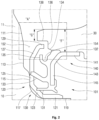
- FIG. 2 is a partially sectional view of a wheel bearing assembly according to the present invention, which corresponds to the part "A" of FIG. 1
- FIG. 3 is an enlarged view of the part "A" of FIG. 2 .
- the horizontal direction in FIG. 2 is referred to as the axial direction
- the left side is referred to as the outward side
- the right side is referred to as the inward side
- the vertical direction as the radial direction.
- FIG. 2 illustrates a portion of the wheel bearing assembly according to the present invention corresponding to the part "A" of FIG. 1 , and rolling elements are omitted in the drawing.
- the wheel bearing assembly includes a hub 10, an outer ring 30, a plurality of rolling elements aligned between the outer ring 30 and the hub 10 in the circumferential direction, and a sealing device 101 provided at an outward opening formed between the outer ring 30 and the hub 10.
- the hub 10 is formed cylindrically.
- One or two inner rings can be further provided on the outer diameter of the hub 10 axially inward of the hub 10. If one inner ring is provided, an inner ring track is formed on the hub 10 and the outer circumferential surface of the inner ring, and if two inner rings are provided, an inner ring track is formed on the outer circumferential surface of the inner rings.
- a flange 11 extending radially is provided on the axial outward of the hub 10.
- the flange 11 is formed in a disc shape extending in the circumferential direction of the hub 10.
- the hub 10 is coupled to a wheel (not illustrated) by the flange 11.
- a flange slope part 111, a flange extension part 113, a flange insertion part 115, and a hub outer diameter part 119 are formed from the radial outside.
- the flange slope part 111 is formed at a position facing the axial outward end of the outer ring 30 from the radial outside of the flange 11.
- the flange slope part 111 is inclined axially inward and radially outward.
- the flange extension part 113 is located radially inward of the flange slope part 111 and extends radially inward from the flange slope part 111.
- the flange insertion part 115 is located radially inward of the flange extension part 113.
- the flange insertion part 115 protrudes axially inward with a step from the radial inside of the flange extension part 113.
- the hub outer diameter part 119 is located radially inward of the flange insertion part 115.
- the hub outer diameter part 119 extends axially inward from the radial inside of the flange insertion part 115.
- the hub outer diameter part 119 is formed cylindrically.
- a hub concave part 117 may be formed between the hub outer diameter part 119 and the flange insertion part 115 in the radial direction.
- the hub concave part 117 is formed concavely between the hub outer diameter part 119 and the flange insertion part 115 axially inward and radially outward.
- the outer ring 30 is formed in a ring shape to surround the outer circumferential surface of the hub 10.
- the outer ring 30 is radially spaced from the hub 10.
- the inner circumferential surface of the outer ring 30 is spaced from the outer circumferential surface of the hub 10.
- the outer ring 30 is coupled to a vehicle body (not illustrated).
- the outer ring 30 includes a first outer ring inner diameter part 132, an outer ring jaw part 136, an outer outer ring slope part 134, and a second outer ring inner diameter part 138 formed axially outward.
- the first outer ring inner diameter part 132 is formed cylindrically.
- the first outer ring inner diameter part 132 is radially spaced from the hub outer diameter part 119 and is provided facing the hub outer diameter part 119.
- the second slinger 140 is press-fitted and fixed into the first outer ring inner diameter part 132.
- the outer ring jaw part 136 is formed on the axial and radial outer side of the first outer ring inner diameter part 132 and is formed extending axially outward.
- the outer ring slope part 134 is formed between the first outer ring inner diameter part 132 and the outer ring jaw part 136.
- the outer ring slope part 134 is formed inclinedly to direct radially inward and axially outward between the first outer ring inner diameter part 132 and the outer ring jaw part 136.
- the second outer ring inner diameter part 138 is formed on the axial outside of the outer ring jaw part 136.
- the second outer ring inner diameter part 138 is formed cylindrically.
- the second outer ring inner diameter part 138 is larger in diameter than the first outer ring inner diameter part 132.
- the ratio of the thickness G of the second outer ring inner diameter part 138 formed on the axial outside of the outer ring 30 from the outer circumferential surface of the outer ring 30 to the thickness F of the first outer ring inner diameter part 132 is in the range of 0.25 ⁇ G/F ⁇ 0.7.
- the thickness G of the second outer ring inner diameter part 138 to the thickness F of the first outer ring inner diameter part 132 is less than 0.25, the thickness G of the second outer ring inner diameter part 138 is formed too thin, so the stiffness and strength of the axial outer end of the outer ring 30 are deteriorated.
- the end face on the axial outside of the outer ring 30, i.e., the end face on the axial outside of the second outer ring inner diameter part 138 serves as the reference surface (backing plate) for turning the outer diameter surface and the inner diameter surface of the axial outside of the outer ring 30 and the flange surface. So, it is necessary to secure a minimum thickness G of the second outer ring inner diameter part 138. If the thickness G of the second outer ring inner diameter part 138 becomes smaller than a certain dimension, it is impossible to perform smooth turning.
- first gap 151 which will be described later, widens, foreign substances entering along the axial outer circumferential surface of the outer ring 30 and the axial inner surface of the hub flange 11 can more easily enter the first gap 151, which is a radial labyrinth structure, leading to a decrease in sealing performance.
- the ratio (G/F) of the thickness G of the second outer ring inner diameter part 138 to the thickness F of the first outer ring inner diameter part 132 is greater than 0.7, the cross-sectional area of the outer ring jaw part 136 facing an inner end 129 of the slinger extension part 129 substantially disappears, so the second gap 155 which is the axial labyrinth structure of the second gap 155 is eliminated and the overall labyrinth sections are reduced and sealing performance is decreased due to the disappearance of the second gap 155.
- the rolling elements are circumferentially arranged between the inner ring track of the hub 10 and the outer ring track of the outer ring 30 which are spaced radially, and are provided in multiple numbers. Grease can be filled in the space where the rolling elements 40 are interposed.
- the sealing device 101 is provided at the axially outward opening formed between the outer ring 30 and the hub 10.
- the sealing device 101 includes a first slinger 120, a second slinger 140, and a seal body 130.
- the first slinger 120 is provided in a ring shape.
- the first slinger 120 is made of a metal material.
- the hub 10 is inserted into the first slinger 120, so the first slinger 120 is provided on the hub 10.
- the first slinger 120 includes a first insertion part 121, a first slinger extension part 125, a first slinger slope part 123, a second slinger slope part 127, and a slinger extension part 129.
- the first insertion part 121 is formed cylindrically.
- the hub outer diameter part 119 is press-fitted into the first insertion part 121.
- the first slinger extension part 125 is provided on the axial outside of the first insertion part 121.
- the first slinger extension part 125 extends radially outward from the first insertion part 121.
- the first slinger extension part 125 is formed in an annular shape.
- the hub 10 is inserted into the first slinger 120, and the axial outside of the first slinger extension part 125 is in close contact with the flange insertion part 115 of the flange 11.
- the first slinger extension part 125 is spaced axially inward from the flange extension part 113.
- the first slinger slope part 123 is formed between the first insertion part 121 and the first slinger extension part 125.
- the first slinger slope part 123 inclinedly extends to be axially outward from the first insertion part 121 and radially outward.
- the first slinger slope part 123 is formed between the first insertion part 121 and the first slinger extension part 125, thereby creating a space between the first slinger slope part 123 and the hub concave part 117.
- the second slinger slope part 127 inclinedly extends to be axially inward from the radial outside of the first slinger extension part 125 and radially outward.
- the second slinger slope part 127 is formed to be away from the flange extension part 112 in the axial direction as moving radially outward.
- An inclination angle ( ⁇ ) of the second slinger slope part 127 is preferably at 15° or more.
- the second slinger slope part 127 is located radially inward of the flange slope part 111 of the flange 11.
- the second slinger slope part 127 and the flange slope part 111 are formed inclined in opposite directions to each other.
- the slinger extension part 129 is formed cylindrically.
- the slinger extension part 129 extends axially inward from the radial outside of the second slinger slope part 127.
- the slinger extension part 129 is radially spaced from the first insertion part 121.
- the outer diameter surface of the slinger extension part 129 is spaced radially inward from the second outer ring inner diameter part 138 of the outer ring to form a first gap 151.
- the first gap 151 is formed axially.
- a slinger end 1291 which is the axial inner end of the slinger extension part 129 is spaced axially outward from the outer ring jaw part 136 to form a second gap 153.
- the second gap 153 is formed radially.
- the slinger extension part 129 may inclinedly extend radially outward from the radial outside of the second slinger slope part 127 so that the outer diameter is increased toward the end 1291.
- "B" represents a radial extension line of the axial outer end of the outer ring 30.
- the radial extension line (B in FIG. 3 ) of the axial outer end of the outer ring 30 is located at a convex curved part formed between the second slinger slope part 127 and the slinger extension part 129.
- Foreign substances flowing along the outer circumferential surface of the outer ring 30 falls into the convex curved part formed between the second slinger slope part 127 and the slinger extension part 129 when flowing radially inward (direction "C" in FIG. 3 ) after passing the axial outer end of the outer ring 30, and then, flows along the outer surface of the first slinger 120 and flows into the first space 152 formed between the flange extension part 113 and the first slinger 120. So, the flow of the foreign substances into the first gap 151 is inhibited.
- the first space 152 is formed to be wider radially outward.
- An axial distance (E) from the flange extension part 113 to the radial outer end of the second slinger slope part 127 is preferably greater than 0.8 mm.
- the axial distance (E) from the flange extension part 113 to the radial outer end of the second slinger slope part 127 can be increased by providing the second slinger slope part 127, thus further inhibiting the flow of foreign substances into the first gap 151.
- foreign substances such as water flowing radially inward along the inner surface of the flange 11 (direction "D" in FIG. 3 ) direct the second slinger slope part 127 axially inward while passing the flange slope part 111, and then direct axially outward at the second slinger slope part 127 to flow into the first space 152 formed between the flange 11 and the first slinger 120.
- the radial inner end of the flange slope part 111 is located at the same position as the outer diameter of the second slinger slope part 127 or radially inward of the second slinger slope part 127.
- the foreign substances entering the first space 152 is expelled downwards as the hub 10 rotates.
- the second slinger 140 is provided in a ring shape.
- the second slinger 140 is made of a metal material.
- the second slinger 140 is inserted into the outer ring 30.
- the second slinger 140 is located axially inward of the first slinger 120.
- the second slinger 140 includes a second insertion part 141, a second slinger extension part 145, and a second slinger slope part 143.
- the second insertion part 141 is formed cylindrically.
- the second insertion part 141 is press-fitted into the first outer ring inner diameter part 132 of the outer ring.
- the second slinger extension part 145 extends radially inward from the axial outer side of the second insertion part 141.
- the second slinger extension part 145 is formed in an annular shape.
- the second slinger extension part 145 is spaced axially inward from the first slinger extension part 125 and faces the first slinger extension part 125.
- the second slinger slope part 143 is formed between the second insertion part 141 and the second slinger extension part 145 in the radial direction.
- the second slinger slope part 143 inclinedly extends to be radially inward and axially outward from the second insertion part 141.
- the second slinger slope part 143 is formed to be away from the outer ring slope part 134 as moving axially outward.
- the second slinger slope part 143 is located radially inward of the outer ring slope part 134 of the outer ring 30.
- the second slinger slope part 143 and the outer ring slope part 134 are formed inclined in opposite directions to each other.
- the seal body 130 is coupled to the axial outside of the second slinger 140.
- the seal body 130 is made of a material such as rubber.
- the seal body 130 includes one or more seal lips that is in contact with the first slinger 120.
- the one or more seal lips protrude axially outward toward the first slinger 120 and extend circumferentially.
- the one or more seal lips are spaced in the radial direction.
- reference numeral 131 indicates a seal lip which protrudes axially outward from the radial inside of the second slinger 140 and is in contact with the first slinger slope part 123
- 133 indicates a seal lip which is spaced from the seal lip 131 in the radial direction, and of which an end is in contact with the first slinger extension part 125.
- the seal body 130 further includes a first seal lip 135 formed on the radial outside of the seal lips.
- the first seal lip 135 extends axially outward from the radial outside of the seal lip 133, and then, extends radially outward to form a "U"-shaped second space 154 on the axial inside of the first seal lip 135.
- a third gap 155 is formed between the end of the first seal lip 135 and the slinger extension part 129. The third gap 155 is formed axially.
- the axial inner end of the slinger extension part 129 is spaced axially inward of the end of the first seal lip 135 ("A" in FIG. 3 ). Therefore, foreign substances flowing through the first gap 151 and the second gap 153 is prevented from entering the second space 154 formed by the first seal lip 135 and directly moving toward the seal lips 133 and 131.
- an interval H1 of the first gap 151 is formed smaller than the interval H2 of the second gap 153 and the interval H3 of the third gap 155. Since the first gap 151 is directly communicated with the exterior, it is preferable for the first gap 151 to be formed as small as possible to prevent the ingress of external foreign substances.
- the intervals H2 and H3 of the second gap 153 and the third gap 155 are smaller than the interval H1 of the first gap 151, it causes tilting deformation of the hub 10 due to moment loads generated by vehicle turning and impacts, and the tilting deformation of the hub 10 may cause the inner end 1291 of the slinger extension part 129 and the second slinger slope part 127 to get in contact with the outer ring jaw part 136 and the first seal lip 135, thus causing damage to the slinger 120 and an increase in drag torque due to interference from the first seal lip 135.
- the interval H2 of the second gap 153 is smaller than the interval H3 of the third gap 155.
- the interval H1 of the first gap 151 is smaller than the interval H2 of the second gap 153, and the interval H2 of the second gap 153 is smaller than the interval H3 of the third gap 155.
- the intervals H1, H2 and H3 of the first to third gaps 151, 153 and 155 are formed in the range of 0.4 to 0.8 mm.
- the interval H1 of the first gap 151 ranges from 0.4 to 0.8 mm
- the interval H2 of the second gap 153 ranges from 0.5 to 0.9 mm
- the interval H3 of the third gap 155 ranges from 0.6 to 1.0 mm.
- the first slinger 120 comes into contact with the outer ring 30 and the first seal lip 135 due to application of external loads, leading to an increase of torque due to damage to the slinger and interference from the seal lip. If the interval of the gap exceeds 1.0 mm, the path through which the external foreign substances enter becomes wider, reducing the labyrinth effect.
- the seal body 130 may further include an outer ring contact part 137 protruding radially outward from the axial inside of the first seal lip 135.
- the outer ring contact part 137 is coupled to the axial outer surface of the second slinger 140 inside the first seal lip 135.
- the outer ring contact part 137 is also coupled to the axial outer surface of the second slinger slope part 143 inside the first seal lip 135.
- the outer diameter of the outer ring contact part 137 is formed larger than the outer diameter of the second insertion part 141.
- the outer ring contact part 137 prevents the foreign substances from entering between the first outer ring inner diameter part 132 and the second insertion part 141 of the second slinger 140 by coming into contact with the first outer ring inner diameter part 132 of the outer ring 30 when the second slinger 140 is assembled.
- the outer ring slope part 134 is formed axially outward of the outer ring contact part 137, thereby enhancing the effect of discharging foreign substances that have entered the second space 154 through the second gap 153. It is preferable that the outer ring slope part 134 is formed with an inclination of at least 5 degrees.
- the foreign substances flow inward in the axial direction and pass through the first gap 151, flow inward in the radial direction and pass through the second gap 153, and then, flow axially outward and pass through the third gap 155 to reach the seal lips 133 and 131, thereby preventing the ingress of the foreign substances to the axial inside of the sealing device 101.
- the slinger extension part 129 is formed to increase in outer diameter towards the end 1291 by extending radially outward from the radial outside of the second slinger slope part 127, the foreign substances that have entered the second space 154 through the gaps are guided along the inner surface of the radially outwardly inclined slinger extension part 129 to the second gap 153 when the hub 10 rotates, thereby being discharged more smoothly.
Landscapes
- Engineering & Computer Science (AREA)
- General Engineering & Computer Science (AREA)
- Mechanical Engineering (AREA)
- Rolling Contact Bearings (AREA)
Abstract
Wheel bearing assembly including a sealing device (101), which includes a first slinger (120) into which the hub (10) is inserted, a second slinger (140) which is inserted into the outer ring, and a seal body (130) which includes one or more seal lips being in contact with the first slinger. A first gap and a second gap of labyrinth are formed between the first slinger and the outer ring, and the seal body further includes a first seal lip formed on the radial outside of the seal lips to form a third gap between the first seal lip and the first slinger.
Description
- The present invention relates to a wheel bearing assembly and, more specifically, to a wheel bearing assembly having excellent sealing performance.
- In general, a bearing is a mechanical component mounted between a rotating element and a non-rotating element to facilitate the rotation of the rotating element. Currently, various types of bearings, such as ball bearings, tapered roller bearings, and needle roller bearings, are in use.
- A wheel bearing, as a type of the bearings, supports a wheel, which is the rotating element, to rotate relative to a vehicle body which is the non-rotating element. The wheel bearing includes an inner ring (and/or hub) connected to either the wheel or the vehicle body, an outer ring connected to the other, and rolling elements interposed between the outer and inner rings.
- Since the wheel bearing is fundamentally mounted on the vehicle's wheel, the wheel bearing is exposed to foreign substances such as dust and moisture. When the foreign substances infiltrate the interior of the wheel bearing, they can cause noise and vibration during operation of the wheel bearing and shorten the lifespan of the wheel bearing. Therefore, sealing devices are installed at one or both ends of the wheel bearing to prevent the intrusion of foreign substances.
-
FIG. 1 is a half cross-sectional view of a conventional wheel bearing assembly. As illustrated inFIG. 1 , the wheel bearing assembly includes ahub 10, anouter ring 30, androlling elements 40. Thehub 10 is coupled to the wheel (not illustrated). Moreover, thehub 10 includes aflange 11 to be coupled with the wheel. Aninner ring 20 is provided on thehub 10. - The
flange 11 can be formed in a disc shape extending in the circumferential direction of thehub 10. Theouter ring 30 is formed to surround the outer surface of thehub 10, and the outer surface of thehub 10 and the inner surface of theouter ring 30 are spaced apart. Additionally, theouter ring 30 is coupled to the vehicle body (not illustrated). - The
rolling elements 40 are aligned between the track of thehub 10 and the track of theouter ring 30, which are spaced apart from each other. Multiplerolling elements 40 are provided. Furthermore, to facilitate the smooth operation of the wheel bearing, grease can be filled in the space where therolling elements 40 are interposed. InFIG. 1 ,reference numeral 42 indicates a cage functioning to maintain a circumferential interval of the rolling elements. - In general, the hub and the inner ring of the wheel bearing assembly are connected to either the wheel or the vehicle body, and the outer ring is connected to the other of the wheel or the vehicle body, which is not connected to the hub and the inner ring. Meanwhile,
FIG. 1 illustrates theouter ring 30 connected to the vehicle body (not illustrated) and thehub 10 connected to the wheel (not illustrated), but is not limited thereto. - The wheel bearing assembly includes
sealing devices sealing devices rolling elements 40 are interposed, and also prevent the leakage of grease. - The
sealing device 50 provided at an outward opening formed between thehub 10 and theouter ring 30 includes a slinger into which theouter ring 30 adjacent to thehub 10 is press-fitted, and a plurality of lips being in contact with thehub 10 while wrapping around the slinger. The outer ring is inserted into the slinger such that an outercircumferential surface 32 and across-sectional face 34 of the outer ring is in contact with the slinger. Some of the plurality of lips are in contact with abent part 16 of thehub 10, and others are in contact with aconcave part 18 of thehub 10. - The
sealing device 80 provided at an inward opening formed between thehub 10 and theouter ring 30 is inserted between an innercircumferential surface 36 of theouter ring 30 and an outercircumferential surface 22 of theinner ring 20 of thehub 10.Reference numeral 12 indicates an outer circumferential surface of thehub 10 into which theinner ring 20 is inserted, and 14 indicates an orbital forming part. - The sealing performance of the
sealing device 50 and the amount of drag torques generated by the friction between the rotating element and the non-rotating element are proportionally related to each other, so when the sealing performance is improved, it tends to increase the drag torque, and when the drag torques are reduced, it tends to decrease the sealing performance. Accordingly, a labyrinth seal structure is applied to the contact sealing devices due to the demand for low-torque and high-sealing performance. However, the labyrinth seal structure cannot effectively prevent the intrusion of foreign substances such as moisture. - Patent Document 1:
Korean Patent Publication No. 10-2012-0114818 - Accordingly, the present invention has been made to solve the above-mentioned problems occurring in the prior arts, and it is an objective of the present invention to provide a wheel bearing assembly having a labyrinth structure with enhanced sealing performance.
- To accomplish the above object, according to the present invention, there is provided a wheel bearing assembly including a sealing device which includes a first slinger into which the hub is inserted, a second slinger which is inserted into the outer ring, and a seal body which includes one or more seal lips being in contact with the first slinger.
- A first gap and a second gap of labyrinth are formed between the first slinger and the outer ring, and the seal body further includes a first seal lip formed on the radial outside of the seal lips to form a third gap between the first seal lip and the first slinger.
- Moreover, foreign substances pass sequentially through the first gap, the second gap, and the third gap, wherein the first gap is formed axially, the second gap is formed radially, and the third gap is formed axially.
- Furthermore, the foreign substances flow axially inward and pass through the first gap, flows radially inward and pass through the second gap, and then, flow axially outward and pass through the third gap to reach the seal lip.
- Additionally, the first slinger includes a first insertion part into which a hub outer diameter part is inserted, a first slinger extension part provided on the outside of the first insertion part and extending radially outward, a second slinger slope part inclinedly extending to direct inward from the first slinger extension part and radially outward, and a slinger extension part extending inward from the second slinger slope part.
- The second slinger includes a second insertion part inserted into a first outer ring inner diameter part, and a second slinger extension part extending radially inward from the outside of the second insertion part and spaced inwardly from the first slinger extension part to face the first slinger extension.
- The seal body is coupled to the second slinger, the one or more seal lips protrude outward toward the first slinger, and the first seal lip extends outward from the radial outside of the seal lips and then extends radially outward to form the third gap between an end thereof and the slinger extension part.
- In addition, the outer ring includes a first outer ring inner diameter part into which the second slinger is inserted, an outer ring jaw part formed outwardly from the first outer ring inner diameter part, and a second outer ring inner diameter part being larger in diameter than the first outer ring inner diameter part on the outside of the outer ring jaw part.
- The first slinger includes a slinger extension part formed radially outward.
- The first gap is formed between the second outer ring inner diameter part and an outer diameter part of the slinger extension part, and the second gap is formed between the outer ring jaw part and the inner end of the slinger extension part, so the first gap and the second gap form a curved gap.
- Moreover, the flange includes a flange slope part directing inward at a position facing the outer end of the outer ring and inclined radially outward, a flange extension part extending radially inward from the flange slope part, and a flange insertion part protruding inward with a step formed radially inward of the flange extension part.
- The first slinger extension is in close contact with the flange insertion part.
- The second slinger slope part is located radially inward of the flange slope part, and the first slinger extension part is spaced axially inward from the flange extension.
- Furthermore, the inner end of the slinger extension is positioned axially inward from the end of the first seal lip.
- Additionally, a radial extension line of the outer end of the outer ring is located at a convex curved part formed between the second slinger slope part and the slinger extension.
- In addition, a first outer ring slope part which is inclined radially inward and axially outward is provided between the first outer ring inner diameter part and the outer ring jaw part of the outer ring.
- Moreover, an interval of the first gap is smaller than an interval of the second gap and an interval of the third gap.
- Furthermore, the interval of the second gap is smaller than the interval of the third gap.
- Additionally, the interval of the first gap is smaller than the interval of the second gap and the interval of the second gap is smaller than the interval of the third gap.
- The interval of the first gap ranges from 0.4 to 0.8 mm, the interval of the second gap ranges from 0.5 to 0.9 mm, and the interval of the third gap ranges from 0.6 to 1.0 mm.
- In addition, the ratio of the thickness of the second outer ring inner diameter part from the outer circumferential surface of the outer ring to the thickness of the first outer ring inner diameter part from the outer circumferential surface of the outer ring is 0.25 ≤ G/F ≤ 0.7.
- As described above, the wheel bearing assembly according to the present invention has the labyrinth structure, which includes the first space formed between the first slinger of the sealing device and the flange, gaps between the first slinger, the outer ring, and the seal body, and the second space formed between the first slinger and the seal body, thereby preventing foreign substances from entering from outside, and enhancing sealing performance without an increase in torque.
-
-
FIG. 1 is a half cross-sectional view of a conventional wheel bearing assembly. -
FIG. 2 is a partially sectional view of a wheel bearing assembly according to the present invention, which corresponds to the part "A" ofFIG. 1 . -
FIG. 3 is an enlarged view of the part "A" ofFIG. 2 . - All technical and scientific terms used in the description of the present invention, unless otherwise defined, are to be understood as commonly understood by those of ordinary skill in the art to which the present disclosure belongs. All terms used in the present disclosure are selected for the purpose of further clarifying the present disclosure and not intended to limit the scope of the present invention as disclosed.
- Expressions such as "comprising," "having," and "including" used in the description of the present invention are to be understood as open-ended terms that imply the possibility of including other embodiments, unless otherwise specified in the phrases or sentences where such expressions are included.
- Expressions in the singular form used in the description of the present invention are intended to include the plural form as well, unless otherwise specified, and are equally applied to the expressions in the singular form described in the claims.
- Expressions such as "first," "second," etc., used in the description of the present invention are used to distinguish a plurality of components and do not limit the order or importance of the components.
- When it is mentioned in the description of the present invention that one component is "connected" or "coupled" to another component, it is to be understood that the one component can be directly connected or coupled to the other component, or be connected or coupled via another intermediate component.
- Hereinafter, a wheel bearing assembly of the present invention will be described in detail with reference to the attached drawings.
-
FIG. 2 is a partially sectional view of a wheel bearing assembly according to the present invention, which corresponds to the part "A" ofFIG. 1 , andFIG. 3 is an enlarged view of the part "A" ofFIG. 2 . - In the following description, the horizontal direction in
FIG. 2 is referred to as the axial direction, the left side is referred to as the outward side, the right side as the inward side, and the vertical direction as the radial direction. - In describing the wheel bearing assembly according to the present invention, descriptions of the content described in the conventional technology are omitted, and only the characteristic configurations of the wheel bearing assembly according to the present invention are described.
-
FIG. 2 illustrates a portion of the wheel bearing assembly according to the present invention corresponding to the part "A" ofFIG. 1 , and rolling elements are omitted in the drawing. - As illustrated in
FIG. 2 , the wheel bearing assembly includes ahub 10, anouter ring 30, a plurality of rolling elements aligned between theouter ring 30 and thehub 10 in the circumferential direction, and asealing device 101 provided at an outward opening formed between theouter ring 30 and thehub 10. - The
hub 10 is formed cylindrically. One or two inner rings (not illustrated) can be further provided on the outer diameter of thehub 10 axially inward of thehub 10. If one inner ring is provided, an inner ring track is formed on thehub 10 and the outer circumferential surface of the inner ring, and if two inner rings are provided, an inner ring track is formed on the outer circumferential surface of the inner rings. - A
flange 11 extending radially is provided on the axial outward of thehub 10. Theflange 11 is formed in a disc shape extending in the circumferential direction of thehub 10. Thehub 10 is coupled to a wheel (not illustrated) by theflange 11. - On the axial inward face of the
flange 11, aflange slope part 111, aflange extension part 113, aflange insertion part 115, and a hubouter diameter part 119 are formed from the radial outside. - The
flange slope part 111 is formed at a position facing the axial outward end of theouter ring 30 from the radial outside of theflange 11. Theflange slope part 111 is inclined axially inward and radially outward. - The
flange extension part 113 is located radially inward of theflange slope part 111 and extends radially inward from theflange slope part 111. - The
flange insertion part 115 is located radially inward of theflange extension part 113. Theflange insertion part 115 protrudes axially inward with a step from the radial inside of theflange extension part 113. - The hub
outer diameter part 119 is located radially inward of theflange insertion part 115. The hubouter diameter part 119 extends axially inward from the radial inside of theflange insertion part 115. The hubouter diameter part 119 is formed cylindrically. - A hub
concave part 117 may be formed between the hubouter diameter part 119 and theflange insertion part 115 in the radial direction. The hub concavepart 117 is formed concavely between the hubouter diameter part 119 and theflange insertion part 115 axially inward and radially outward. - The
outer ring 30 is formed in a ring shape to surround the outer circumferential surface of thehub 10. Theouter ring 30 is radially spaced from thehub 10. The inner circumferential surface of theouter ring 30 is spaced from the outer circumferential surface of thehub 10. Theouter ring 30 is coupled to a vehicle body (not illustrated). - The
outer ring 30 includes a first outer ringinner diameter part 132, an outerring jaw part 136, an outer outerring slope part 134, and a second outer ringinner diameter part 138 formed axially outward. - The first outer ring
inner diameter part 132 is formed cylindrically. The first outer ringinner diameter part 132 is radially spaced from the hubouter diameter part 119 and is provided facing the hubouter diameter part 119. Thesecond slinger 140 is press-fitted and fixed into the first outer ringinner diameter part 132. - The outer
ring jaw part 136 is formed on the axial and radial outer side of the first outer ringinner diameter part 132 and is formed extending axially outward. - The outer
ring slope part 134 is formed between the first outer ringinner diameter part 132 and the outerring jaw part 136. The outerring slope part 134 is formed inclinedly to direct radially inward and axially outward between the first outer ringinner diameter part 132 and the outerring jaw part 136. - The second outer ring
inner diameter part 138 is formed on the axial outside of the outerring jaw part 136. The second outer ringinner diameter part 138 is formed cylindrically. The second outer ringinner diameter part 138 is larger in diameter than the first outer ringinner diameter part 132. - As illustrated in
FIG. 2 , the ratio of the thickness G of the second outer ringinner diameter part 138 formed on the axial outside of theouter ring 30 from the outer circumferential surface of theouter ring 30 to the thickness F of the first outer ringinner diameter part 132 is in the range of 0.25 ≤ G/F ≤ 0.7. - If the ratio (G/F) of the thickness G of the second outer ring
inner diameter part 138 to the thickness F of the first outer ringinner diameter part 132 is less than 0.25, the thickness G of the second outer ringinner diameter part 138 is formed too thin, so the stiffness and strength of the axial outer end of theouter ring 30 are deteriorated. - Additionally, the end face on the axial outside of the
outer ring 30, i.e., the end face on the axial outside of the second outer ringinner diameter part 138, serves as the reference surface (backing plate) for turning the outer diameter surface and the inner diameter surface of the axial outside of theouter ring 30 and the flange surface. So, it is necessary to secure a minimum thickness G of the second outer ringinner diameter part 138. If the thickness G of the second outer ringinner diameter part 138 becomes smaller than a certain dimension, it is impossible to perform smooth turning. - Additionally, as an interval H1 of a
first gap 151, which will be described later, widens, foreign substances entering along the axial outer circumferential surface of theouter ring 30 and the axial inner surface of thehub flange 11 can more easily enter thefirst gap 151, which is a radial labyrinth structure, leading to a decrease in sealing performance. - Additionally, if the ratio (G/F) of the thickness G of the second outer ring
inner diameter part 138 to the thickness F of the first outer ringinner diameter part 132 is greater than 0.7, the cross-sectional area of the outerring jaw part 136 facing aninner end 129 of theslinger extension part 129 substantially disappears, so thesecond gap 155 which is the axial labyrinth structure of thesecond gap 155 is eliminated and the overall labyrinth sections are reduced and sealing performance is decreased due to the disappearance of thesecond gap 155. - The rolling elements are circumferentially arranged between the inner ring track of the
hub 10 and the outer ring track of theouter ring 30 which are spaced radially, and are provided in multiple numbers. Grease can be filled in the space where the rollingelements 40 are interposed. - The
sealing device 101 is provided at the axially outward opening formed between theouter ring 30 and thehub 10. Thesealing device 101 includes afirst slinger 120, asecond slinger 140, and aseal body 130. - The
first slinger 120 is provided in a ring shape. Thefirst slinger 120 is made of a metal material. Thehub 10 is inserted into thefirst slinger 120, so thefirst slinger 120 is provided on thehub 10. - The
first slinger 120 includes afirst insertion part 121, a firstslinger extension part 125, a firstslinger slope part 123, a secondslinger slope part 127, and aslinger extension part 129. - The
first insertion part 121 is formed cylindrically. The hubouter diameter part 119 is press-fitted into thefirst insertion part 121. - The first
slinger extension part 125 is provided on the axial outside of thefirst insertion part 121. The firstslinger extension part 125 extends radially outward from thefirst insertion part 121. The firstslinger extension part 125 is formed in an annular shape. - The
hub 10 is inserted into thefirst slinger 120, and the axial outside of the firstslinger extension part 125 is in close contact with theflange insertion part 115 of theflange 11. The firstslinger extension part 125 is spaced axially inward from theflange extension part 113. - The first
slinger slope part 123 is formed between thefirst insertion part 121 and the firstslinger extension part 125. The firstslinger slope part 123 inclinedly extends to be axially outward from thefirst insertion part 121 and radially outward. The firstslinger slope part 123 is formed between thefirst insertion part 121 and the firstslinger extension part 125, thereby creating a space between the firstslinger slope part 123 and the hubconcave part 117. - The second
slinger slope part 127 inclinedly extends to be axially inward from the radial outside of the firstslinger extension part 125 and radially outward. The secondslinger slope part 127 is formed to be away from the flange extension part 112 in the axial direction as moving radially outward. An inclination angle (θ) of the secondslinger slope part 127 is preferably at 15° or more. The secondslinger slope part 127 is located radially inward of theflange slope part 111 of theflange 11. The secondslinger slope part 127 and theflange slope part 111 are formed inclined in opposite directions to each other. - The
slinger extension part 129 is formed cylindrically. Theslinger extension part 129 extends axially inward from the radial outside of the secondslinger slope part 127. Theslinger extension part 129 is radially spaced from thefirst insertion part 121. - The outer diameter surface of the
slinger extension part 129 is spaced radially inward from the second outer ringinner diameter part 138 of the outer ring to form afirst gap 151. Thefirst gap 151 is formed axially. - A
slinger end 1291 which is the axial inner end of theslinger extension part 129 is spaced axially outward from the outerring jaw part 136 to form asecond gap 153. Thesecond gap 153 is formed radially. - The
slinger extension part 129 may inclinedly extend radially outward from the radial outside of the secondslinger slope part 127 so that the outer diameter is increased toward theend 1291. - In
FIG. 3 , "B" represents a radial extension line of the axial outer end of theouter ring 30. The radial extension line (B inFIG. 3 ) of the axial outer end of theouter ring 30 is located at a convex curved part formed between the secondslinger slope part 127 and theslinger extension part 129. - Foreign substances flowing along the outer circumferential surface of the
outer ring 30 falls into the convex curved part formed between the secondslinger slope part 127 and theslinger extension part 129 when flowing radially inward (direction "C" inFIG. 3 ) after passing the axial outer end of theouter ring 30, and then, flows along the outer surface of thefirst slinger 120 and flows into thefirst space 152 formed between theflange extension part 113 and thefirst slinger 120. So, the flow of the foreign substances into thefirst gap 151 is inhibited. Thefirst space 152 is formed to be wider radially outward. - An axial distance (E) from the
flange extension part 113 to the radial outer end of the secondslinger slope part 127 is preferably greater than 0.8 mm. The axial distance (E) from theflange extension part 113 to the radial outer end of the secondslinger slope part 127 can be increased by providing the secondslinger slope part 127, thus further inhibiting the flow of foreign substances into thefirst gap 151. - Additionally, as illustrated in
FIG. 3 , foreign substances such as water flowing radially inward along the inner surface of the flange 11 (direction "D" inFIG. 3 ) direct the secondslinger slope part 127 axially inward while passing theflange slope part 111, and then direct axially outward at the secondslinger slope part 127 to flow into thefirst space 152 formed between theflange 11 and thefirst slinger 120. The radial inner end of theflange slope part 111 is located at the same position as the outer diameter of the secondslinger slope part 127 or radially inward of the secondslinger slope part 127. - Therefore, the foreign substances flowing radially inward along the inner surface of the
flange 11 is inhibited from flowing into thefirst gap 151. - The foreign substances entering the
first space 152 is expelled downwards as thehub 10 rotates. - The
second slinger 140 is provided in a ring shape. Thesecond slinger 140 is made of a metal material. Thesecond slinger 140 is inserted into theouter ring 30. Thesecond slinger 140 is located axially inward of thefirst slinger 120. Thesecond slinger 140 includes asecond insertion part 141, a secondslinger extension part 145, and a secondslinger slope part 143. - The
second insertion part 141 is formed cylindrically. Thesecond insertion part 141 is press-fitted into the first outer ringinner diameter part 132 of the outer ring. - The second
slinger extension part 145 extends radially inward from the axial outer side of thesecond insertion part 141. The secondslinger extension part 145 is formed in an annular shape. The secondslinger extension part 145 is spaced axially inward from the firstslinger extension part 125 and faces the firstslinger extension part 125. - The second
slinger slope part 143 is formed between thesecond insertion part 141 and the secondslinger extension part 145 in the radial direction. The secondslinger slope part 143 inclinedly extends to be radially inward and axially outward from thesecond insertion part 141. The secondslinger slope part 143 is formed to be away from the outerring slope part 134 as moving axially outward. The secondslinger slope part 143 is located radially inward of the outerring slope part 134 of theouter ring 30. The secondslinger slope part 143 and the outerring slope part 134 are formed inclined in opposite directions to each other. - The
seal body 130 is coupled to the axial outside of thesecond slinger 140. Theseal body 130 is made of a material such as rubber. Theseal body 130 includes one or more seal lips that is in contact with thefirst slinger 120. - The one or more seal lips protrude axially outward toward the
first slinger 120 and extend circumferentially. The one or more seal lips are spaced in the radial direction. - In
FIG. 2 ,reference numeral 131 indicates a seal lip which protrudes axially outward from the radial inside of thesecond slinger 140 and is in contact with the firstslinger slope part seal lip 131 in the radial direction, and of which an end is in contact with the firstslinger extension part 125. - The
seal body 130 further includes afirst seal lip 135 formed on the radial outside of the seal lips. - The
first seal lip 135 extends axially outward from the radial outside of theseal lip 133, and then, extends radially outward to form a "U"-shapedsecond space 154 on the axial inside of thefirst seal lip 135. Athird gap 155 is formed between the end of thefirst seal lip 135 and theslinger extension part 129. Thethird gap 155 is formed axially. - The axial inner end of the
slinger extension part 129 is spaced axially inward of the end of the first seal lip 135 ("A" inFIG. 3 ). Therefore, foreign substances flowing through thefirst gap 151 and thesecond gap 153 is prevented from entering thesecond space 154 formed by thefirst seal lip 135 and directly moving toward theseal lips - As illustrated in
FIG. 3 , an interval H1 of thefirst gap 151 is formed smaller than the interval H2 of thesecond gap 153 and the interval H3 of thethird gap 155. Since thefirst gap 151 is directly communicated with the exterior, it is preferable for thefirst gap 151 to be formed as small as possible to prevent the ingress of external foreign substances. - If the intervals H2 and H3 of the
second gap 153 and thethird gap 155 are smaller than the interval H1 of thefirst gap 151, it causes tilting deformation of thehub 10 due to moment loads generated by vehicle turning and impacts, and the tilting deformation of thehub 10 may cause theinner end 1291 of theslinger extension part 129 and the secondslinger slope part 127 to get in contact with the outerring jaw part 136 and thefirst seal lip 135, thus causing damage to theslinger 120 and an increase in drag torque due to interference from thefirst seal lip 135. - It is preferable that the interval H2 of the
second gap 153 is smaller than the interval H3 of thethird gap 155. - If the interval H3 of the
third gap 155 is smaller than the interval H2 of thesecond gap 153, the problem where the secondslinger slope part 127 comes into contact with thefirst seal lip 135 before theinner end 1291 of theslinger extension part 129 comes into contact with the outerring jaw part 136. - Therefore, it is preferable that the interval H1 of the
first gap 151 is smaller than the interval H2 of thesecond gap 153, and the interval H2 of thesecond gap 153 is smaller than the interval H3 of thethird gap 155. - The intervals H1, H2 and H3 of the first to
third gaps first gap 151 ranges from 0.4 to 0.8 mm, the interval H2 of thesecond gap 153 ranges from 0.5 to 0.9 mm, and the interval H3 of thethird gap 155 ranges from 0.6 to 1.0 mm. - If the interval of the gap is less than 0.4 mm, the
first slinger 120 comes into contact with theouter ring 30 and thefirst seal lip 135 due to application of external loads, leading to an increase of torque due to damage to the slinger and interference from the seal lip. If the interval of the gap exceeds 1.0 mm, the path through which the external foreign substances enter becomes wider, reducing the labyrinth effect. - The
seal body 130 may further include an outerring contact part 137 protruding radially outward from the axial inside of thefirst seal lip 135. - The outer
ring contact part 137 is coupled to the axial outer surface of thesecond slinger 140 inside thefirst seal lip 135. The outerring contact part 137 is also coupled to the axial outer surface of the secondslinger slope part 143 inside thefirst seal lip 135. The outer diameter of the outerring contact part 137 is formed larger than the outer diameter of thesecond insertion part 141. - The outer
ring contact part 137 prevents the foreign substances from entering between the first outer ringinner diameter part 132 and thesecond insertion part 141 of thesecond slinger 140 by coming into contact with the first outer ringinner diameter part 132 of theouter ring 30 when thesecond slinger 140 is assembled. - Additionally, on the
outer ring 30, the outerring slope part 134 is formed axially outward of the outerring contact part 137, thereby enhancing the effect of discharging foreign substances that have entered thesecond space 154 through thesecond gap 153. It is preferable that the outerring slope part 134 is formed with an inclination of at least 5 degrees. - If foreign substances penetrate through the first to
third gaps first gap 151, the radially formedsecond gap 153, and the axially formedthird gap 155. - Thus, the foreign substances flow inward in the axial direction and pass through the
first gap 151, flow inward in the radial direction and pass through thesecond gap 153, and then, flow axially outward and pass through thethird gap 155 to reach theseal lips sealing device 101. - Furthermore, if the
slinger extension part 129 is formed to increase in outer diameter towards theend 1291 by extending radially outward from the radial outside of the secondslinger slope part 127, the foreign substances that have entered thesecond space 154 through the gaps are guided along the inner surface of the radially outwardly inclinedslinger extension part 129 to thesecond gap 153 when thehub 10 rotates, thereby being discharged more smoothly.
Claims (13)
- A wheel bearing assembly comprising:an outer ring, a hub, a plurality of rolling elements aligned circumferentially between the outer ring and the hub, and a sealing device provided at an outward opening formed between the outer ring and the hub,wherein the sealing device includes a first slinger into which the hub is inserted, a second slinger which is inserted into the outer ring, and a seal body which includes one or more seal lips being in contact with the first slinger, andwherein a first gap and a second gap of labyrinth are formed between the first slinger and the outer ring, and the seal body further includes a first seal lip formed on the radial outside of the seal lips to form a third gap between the first seal lip and the first slinger.
- The wheel bearing assembly according to claim 1, wherein foreign substances pass sequentially through the first gap, the second gap, and the third gap, wherein the first gap is formed axially, the second gap is formed radially, and the third gap is formed axially.
- The wheel bearing assembly according to claim 2, wherein the foreign substances flow axially inward and pass through the first gap, flows radially inward and pass through the second gap, and then, flow axially outward and pass through the third gap to reach the seal lip.
- The wheel bearing assembly according to any one of claims 1 to 3, wherein the first slinger includes a first insertion part into which a hub outer diameter part is inserted, a first slinger extension part provided on the outside of the first insertion part and extending radially outward, a second slinger slope part inclinedly extending to direct inward from the first slinger extension part and radially outward, and a slinger extension part extending inward from the second slinger slope part,wherein the second slinger includes a second insertion part inserted into a first outer ring inner diameter part, and a second slinger extension part extending radially inward from the outside of the second insertion part and spaced inwardly from the first slinger extension part to face the first slinger extension, andwherein the seal body is coupled to the second slinger, the one or more seal lips protrude outward toward the first slinger, and the first seal lip extends outward from the radial outside of the seal lips and then extends radially outward to form the third gap between an end thereof and the slinger extension part.
- The wheel bearing assembly according to any one of claims 1 to 3, wherein the outer ring includes a first outer ring inner diameter part into which the second slinger is inserted, an outer ring jaw part formed outwardly from the first outer ring inner diameter part, and a second outer ring inner diameter part being larger in diameter than the first outer ring inner diameter part on the outside of the outer ring jaw part,wherein the first slinger includes a slinger extension part formed radially outward, andwherein the first gap is formed between the second outer ring inner diameter part and an outer diameter part of the slinger extension part, and the second gap is formed between the outer ring jaw part and the inner end of the slinger extension part, so the first gap and the second gap form a curved gap.
- The wheel bearing assembly according to claim 3, wherein the flange includes a flange slope part directing inward at a position facing the outer end of the outer ring and inclined radially outward, a flange extension part extending radially inward from the flange slope part, and a flange insertion part protruding inward with a step formed radially inward of the flange extension part,wherein the first slinger extension is in close contact with the flange insertion part, andwherein the second slinger slope part is located radially inward of the flange slope part, and the first slinger extension part is spaced axially inward from the flange extension.
- The wheel bearing assembly according to claim 4, wherein the inner end of the slinger extension is positioned axially inward from the end of the first seal lip.
- The wheel bearing assembly according to claim 3, wherein a radial extension line of the outer end of the outer ring is located at a convex curved part formed between the second slinger slope part and the slinger extension.
- The wheel bearing assembly according to claim 3, wherein a first outer ring slope part which is inclined radially inward and axially outward is provided between the first outer ring inner diameter part and the outer ring jaw part of the outer ring.
- The wheel bearing assembly according to claim 5, wherein an interval of the first gap is smaller than an interval of the second gap and an interval of the third gap.
- The wheel bearing assembly according to claim 10, wherein the interval of the second gap is smaller than the interval of the third gap.
- The wheel bearing assembly according to claim 11, wherein the interval of the first gap is smaller than the interval of the second gap and the interval of the second gap is smaller than the interval of the third gap, and
wherein the interval of the first gap ranges from 0.4 to 0.8 mm, the interval of the second gap ranges from 0.5 to 0.9 mm, and the interval of the third gap ranges from 0.6 to 1.0 mm. - The wheel bearing assembly according to claim 5, wherein the ratio of the thickness of the second outer ring inner diameter part from the outer circumferential surface of the outer ring to the thickness of the first outer ring inner diameter part from the outer circumferential surface of the outer ring is 0.25 ≤ G/F ≤ 0.7.
Applications Claiming Priority (1)
| Application Number | Priority Date | Filing Date | Title |
|---|---|---|---|
| KR1020230148606A KR102934077B1 (en) | 2023-10-31 | 2023-10-31 | A wheel bearing assembly |
Publications (1)
| Publication Number | Publication Date |
|---|---|
| EP4549765A1 true EP4549765A1 (en) | 2025-05-07 |
Family
ID=93376552
Family Applications (1)
| Application Number | Title | Priority Date | Filing Date |
|---|---|---|---|
| EP24210056.8A Pending EP4549765A1 (en) | 2023-10-31 | 2024-10-31 | A wheel bearing assembly |
Country Status (2)
| Country | Link |
|---|---|
| EP (1) | EP4549765A1 (en) |
| KR (1) | KR102934077B1 (en) |
Citations (7)
| Publication number | Priority date | Publication date | Assignee | Title |
|---|---|---|---|---|
| KR20120114818A (en) | 2011-04-08 | 2012-10-17 | 주식회사 일진글로벌 | Sealing apparatus of bearing and wheel bearing including the same |
| US8734022B2 (en) * | 2010-04-21 | 2014-05-27 | Aktiebolaget Skf | Sealing device for a hub and a bearing assembly including the sealing device |
| US20150003766A1 (en) * | 2013-07-01 | 2015-01-01 | Aktiebolaget Skf | Hub bearing unit equipped with a low friction sealing assembly |
| JP2017166548A (en) * | 2016-03-15 | 2017-09-21 | Ntn株式会社 | Wheel bearing device |
| US9925830B2 (en) * | 2015-05-29 | 2018-03-27 | Aktiebolaget Skf | Bearing rolling including a low friction sealing device, in particular for a hub bearing unit |
| KR101867405B1 (en) * | 2016-08-17 | 2018-06-15 | 주식회사 일진글로벌 | Wheel bearing |
| CN112196902A (en) * | 2020-09-01 | 2021-01-08 | 浙江万向精工有限公司 | A labyrinth type hub bearing unit sealing structure |
Family Cites Families (3)
| Publication number | Priority date | Publication date | Assignee | Title |
|---|---|---|---|---|
| KR101826200B1 (en) | 2016-05-23 | 2018-02-06 | 주식회사 일진글로벌 | Slinger structure and wheel bearing assembly provided the same |
| KR101960720B1 (en) * | 2016-10-05 | 2019-07-17 | 주식회사 일진글로벌 | Wheel bearing |
| JP2018071739A (en) * | 2016-11-02 | 2018-05-10 | 株式会社ジェイテクト | Wheel bearing device |
-
2023
- 2023-10-31 KR KR1020230148606A patent/KR102934077B1/en active Active
-
2024
- 2024-10-31 EP EP24210056.8A patent/EP4549765A1/en active Pending
Patent Citations (7)
| Publication number | Priority date | Publication date | Assignee | Title |
|---|---|---|---|---|
| US8734022B2 (en) * | 2010-04-21 | 2014-05-27 | Aktiebolaget Skf | Sealing device for a hub and a bearing assembly including the sealing device |
| KR20120114818A (en) | 2011-04-08 | 2012-10-17 | 주식회사 일진글로벌 | Sealing apparatus of bearing and wheel bearing including the same |
| US20150003766A1 (en) * | 2013-07-01 | 2015-01-01 | Aktiebolaget Skf | Hub bearing unit equipped with a low friction sealing assembly |
| US9925830B2 (en) * | 2015-05-29 | 2018-03-27 | Aktiebolaget Skf | Bearing rolling including a low friction sealing device, in particular for a hub bearing unit |
| JP2017166548A (en) * | 2016-03-15 | 2017-09-21 | Ntn株式会社 | Wheel bearing device |
| KR101867405B1 (en) * | 2016-08-17 | 2018-06-15 | 주식회사 일진글로벌 | Wheel bearing |
| CN112196902A (en) * | 2020-09-01 | 2021-01-08 | 浙江万向精工有限公司 | A labyrinth type hub bearing unit sealing structure |
Also Published As
| Publication number | Publication date |
|---|---|
| KR102934077B1 (en) | 2026-03-05 |
| KR20250063013A (en) | 2025-05-08 |
Similar Documents
| Publication | Publication Date | Title |
|---|---|---|
| US20070201782A1 (en) | Seal device and rolling bearing unit with seal device | |
| JP4297658B2 (en) | Wheel bearing device | |
| GB2165594A (en) | A rolling bearing having a seal | |
| US20210355996A1 (en) | Wheel bearing device | |
| US20130301970A1 (en) | Wheel rolling bearing unit | |
| CN210978234U (en) | Hub unit bearing with sealing device | |
| US20060239599A1 (en) | Seal for an antifriction bearing | |
| US11965558B2 (en) | Sealing device | |
| JP6755156B2 (en) | Rolling bearing with seal for pulley unit | |
| JP6777466B2 (en) | Pulley unit | |
| JP2013242006A (en) | Rolling bearing with sealing device | |
| JP7119992B2 (en) | hub unit bearing | |
| EP4549765A1 (en) | A wheel bearing assembly | |
| EP1956258A1 (en) | Sealing apparatus and bearing apparatus having the same | |
| KR101960720B1 (en) | Wheel bearing | |
| JP2009197969A (en) | Sealing device for rolling bearing | |
| US12152636B2 (en) | Sealing device | |
| JP2009074589A (en) | Sealing device | |
| JP7604979B2 (en) | Hub unit bearing | |
| JP2009024804A (en) | Sealing device | |
| KR101983270B1 (en) | Wheel bearing assembly | |
| KR102901395B1 (en) | Vehicular wheel bearing comprising improved sealing member | |
| US11761488B2 (en) | Rotatable shield for wheel bearing assemblies | |
| KR102889076B1 (en) | Vehicular wheel bearing comprising improved sealing device | |
| KR101995198B1 (en) | Wheel bearing for vehicle |
Legal Events
| Date | Code | Title | Description |
|---|---|---|---|
| PUAI | Public reference made under article 153(3) epc to a published international application that has entered the european phase |
Free format text: ORIGINAL CODE: 0009012 |
|
| STAA | Information on the status of an ep patent application or granted ep patent |
Free format text: STATUS: REQUEST FOR EXAMINATION WAS MADE |
|
| 17P | Request for examination filed |
Effective date: 20241121 |
|
| AK | Designated contracting states |
Kind code of ref document: A1 Designated state(s): AL AT BE BG CH CY CZ DE DK EE ES FI FR GB GR HR HU IE IS IT LI LT LU LV MC ME MK MT NL NO PL PT RO RS SE SI SK SM TR |