EP4549668A1 - Cabin and work machine - Google Patents
Cabin and work machine Download PDFInfo
- Publication number
- EP4549668A1 EP4549668A1 EP23831262.3A EP23831262A EP4549668A1 EP 4549668 A1 EP4549668 A1 EP 4549668A1 EP 23831262 A EP23831262 A EP 23831262A EP 4549668 A1 EP4549668 A1 EP 4549668A1
- Authority
- EP
- European Patent Office
- Prior art keywords
- window
- lock
- window portion
- frame
- lower window
- Prior art date
- Legal status (The legal status is an assumption and is not a legal conclusion. Google has not performed a legal analysis and makes no representation as to the accuracy of the status listed.)
- Pending
Links
Images




Classifications
-
- B—PERFORMING OPERATIONS; TRANSPORTING
- B60—VEHICLES IN GENERAL
- B60J—WINDOWS, WINDSCREENS, NON-FIXED ROOFS, DOORS, OR SIMILAR DEVICES FOR VEHICLES; REMOVABLE EXTERNAL PROTECTIVE COVERINGS SPECIALLY ADAPTED FOR VEHICLES
- B60J1/00—Windows; Windscreens; Accessories therefor
-
- B—PERFORMING OPERATIONS; TRANSPORTING
- B60—VEHICLES IN GENERAL
- B60S—SERVICING, CLEANING, REPAIRING, SUPPORTING, LIFTING, OR MANOEUVRING OF VEHICLES, NOT OTHERWISE PROVIDED FOR
- B60S1/00—Cleaning of vehicles
- B60S1/02—Cleaning windscreens, windows or optical devices
- B60S1/04—Wipers or the like, e.g. scrapers
- B60S1/043—Attachment of the wiper assembly to the vehicle
- B60S1/0438—Attachement of separate wiper motor assembly to the vehicle
-
- E—FIXED CONSTRUCTIONS
- E02—HYDRAULIC ENGINEERING; FOUNDATIONS; SOIL SHIFTING
- E02F—DREDGING; SOIL-SHIFTING
- E02F3/00—Dredgers; Soil-shifting machines
- E02F3/04—Dredgers; Soil-shifting machines mechanically-driven
- E02F3/28—Dredgers; Soil-shifting machines mechanically-driven with digging tools mounted on a dipper- or bucket-arm, i.e. there is either one arm or a pair of arms, e.g. dippers, buckets
- E02F3/30—Dredgers; Soil-shifting machines mechanically-driven with digging tools mounted on a dipper- or bucket-arm, i.e. there is either one arm or a pair of arms, e.g. dippers, buckets with a dipper-arm pivoted on a cantilever beam, i.e. boom
- E02F3/32—Dredgers; Soil-shifting machines mechanically-driven with digging tools mounted on a dipper- or bucket-arm, i.e. there is either one arm or a pair of arms, e.g. dippers, buckets with a dipper-arm pivoted on a cantilever beam, i.e. boom working downwardly and towards the machine, e.g. with backhoes
- E02F3/325—Backhoes of the miniature type
-
- E—FIXED CONSTRUCTIONS
- E02—HYDRAULIC ENGINEERING; FOUNDATIONS; SOIL SHIFTING
- E02F—DREDGING; SOIL-SHIFTING
- E02F9/00—Component parts of dredgers or soil-shifting machines, not restricted to one of the kinds covered by groups E02F3/00 - E02F7/00
- E02F9/16—Cabins, platforms, or the like, for drivers
-
- E—FIXED CONSTRUCTIONS
- E02—HYDRAULIC ENGINEERING; FOUNDATIONS; SOIL SHIFTING
- E02F—DREDGING; SOIL-SHIFTING
- E02F9/00—Component parts of dredgers or soil-shifting machines, not restricted to one of the kinds covered by groups E02F3/00 - E02F7/00
- E02F9/16—Cabins, platforms, or the like, for drivers
- E02F9/163—Structures to protect drivers, e.g. cabins, doors for cabins; Falling object protection structure [FOPS]; Roll over protection structure [ROPS]
-
- E—FIXED CONSTRUCTIONS
- E02—HYDRAULIC ENGINEERING; FOUNDATIONS; SOIL SHIFTING
- E02F—DREDGING; SOIL-SHIFTING
- E02F9/00—Component parts of dredgers or soil-shifting machines, not restricted to one of the kinds covered by groups E02F3/00 - E02F7/00
- E02F9/16—Cabins, platforms, or the like, for drivers
- E02F9/166—Cabins, platforms, or the like, for drivers movable, tiltable or pivoting, e.g. movable seats, dampening arrangements of cabins
-
- E—FIXED CONSTRUCTIONS
- E05—LOCKS; KEYS; WINDOW OR DOOR FITTINGS; SAFES
- E05C—BOLTS OR FASTENING DEVICES FOR WINGS, SPECIALLY FOR DOORS OR WINDOWS
- E05C1/00—Fastening devices with bolts moving rectilinearly
- E05C1/004—Fastening devices with bolts moving rectilinearly parallel to the surface on which the fastener is mounted
- E05C1/006—Fastening devices with bolts moving rectilinearly parallel to the surface on which the fastener is mounted parallel to the wing edge
-
- E—FIXED CONSTRUCTIONS
- E05—LOCKS; KEYS; WINDOW OR DOOR FITTINGS; SAFES
- E05C—BOLTS OR FASTENING DEVICES FOR WINGS, SPECIALLY FOR DOORS OR WINDOWS
- E05C1/00—Fastening devices with bolts moving rectilinearly
- E05C1/08—Fastening devices with bolts moving rectilinearly with latching action
- E05C1/10—Fastening devices with bolts moving rectilinearly with latching action with operating handle or equivalent member rigid with the latch
Definitions
- the present invention relates to a cabin included in a working machine such as a backhoe, and a working machine including the cabin.
- a front window of a cabin is configured to be divided into upper and lower portions, and a front window glass assembly (upper window portion) that is an upper half portion of the front window is configured to open toward a ceiling portion (upward of an operator's seat) along a rail portion of a cabin framework body surrounding the operator's seat.
- the upper half portion (upper window portion) of the front window opens to the inner upper side of the cabin as described above, and it is conceivable that a lower half portion (lower window portion) of the front window is also openable/closable.
- the lower window portion is configured to open toward the ceiling portion along the rail portion similarly to the upper window portion, it is necessary to provide a space, at the ceiling portion, for accommodating the upper window portion and the lower window portion in an open state and the members belonging to both window portions, and hence there is a problem that a head clearance in the cabin is decreased by that amount.
- the present invention is made to solve such a problem, and an object of the present invention is to make a cabin front window portion fully openable while preventing or reducing a decrease in head clearance in a cabin.
- the present invention employs the following technical means to attain the above-described object.
- a cabin according to an example embodiment of the present invention is a cabin mounted on a working machine.
- the cabin includes a protective frame vertically provided around an operator's seat included in the working machine; a roof provided at an upper portion of the protective frame; and a front window provided at a front portion of the protective frame.
- the front window is vertically divided into an upper window portion, which is coupled to a window frame at the front portion of the protective frame so as to be movable toward a lower surface of the roof, and a lower window portion detachably coupled to the window frame.
- the window frame includes a lower window stay to engage with and support a lower edge of the lower window portion, and a lock receiver to hold a side edge of the lower window portion in a closed position.
- the lower window portion includes at least one lock to be fitted to the lock receiver when the side edge of the lower window portion is overlapped with the window frame.
- the at least one lock may include a plurality of locks disposed on both left and right side edges of the lower window portion.
- the lock or the lock receiver may include a lock release operation element to manually release fitting between the lock and the lock receiver, such that the fitting between the lock and the lock receiver is released by a release operation of the lock release operation element.
- the lock may include a lock body to support the lock release operation element.
- the lock body may be provided on a rear portion of the lower window portion to bulge rearward.
- the lock release operation element may be provided at a side portion of the lock body near a center in a left-right direction of the lower window portion.
- the release operation may be a pulling operation of moving the lock release operation element toward the center in the left-right direction of the lower window portion.
- the lower window portion may include at least one first cutout to engage with the lower window stay and to inhibit the lower window portion from moving in a left-right direction.
- the at least one first cutout may include, on the lower edge of the lower window portion, a pair of first cutouts spaced apart from each other in the left-right direction.
- the cabin may include a wiper to wipe an outer surface of the upper window portion.
- the wiper may include a blade in contact with the outer surface, an arm to support the blade so as to be slidable along the outer surface, and a wiper drive to swing the arm.
- the wiper drive may be provided on the window frame, at a position close to an outside of the window frame in the left-right direction.
- the wiper drive may be provided on the window frame, at a position lower than the upper window portion.
- the window frame may include a wiper bracket to support the wiper drive.
- An upper edge of the wiper bracket may be aligned in the left-right direction with an upper edge of the lower window portion when in the closed position, and may be provided as an abutting end portion to abut against a lower edge of the upper window portion.
- the wiper bracket may include a drive cover to cover the wiper drive.
- the lower window portion may include a second cutout to avoid interference with the drive cover when the lower window portion is attached to or detached from the window frame.
- the lock may be fitted to the lock receiver by the side edge being pressed against the window frame from an inner side to an outer side of the cabin in a state in which the lower edge of the lower window portion is supported by the lower window stay.
- the cabin front window portion it is possible to make the cabin front window portion fully openable while preventing or reducing a decrease in head clearance in the cabin.
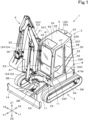
- a working machine 1 of the present embodiment is a backhoe including a turning base (machine body) 2, a traveling device 3, and a working device 4.
- a cabin 5 is mounted on the turning base 2.
- an operator's seat 6 on which an operator is seated is provided inside the cabin 5.
- the working machine 1 is not limited to the backhoe, and may be a working machine of another type.
- a direction in which the operator seated on the operator's seat 6 faces is referred to as front or a forward side of the turning base 2, and a direction opposite thereto (a direction of arrow X2 in FIGS. 1 , 2 , and the like) is referred to as rear or a rearward side of the turning base 2.
- the left side of the operator (a direction of arrow Y1 in FIGS. 3 , 4 , and the like) is referred to as left or a leftward side of the turning base 2
- the right side of the operator is a direction of arrow Y2 in FIGS.
- the turning base 2 is referred to as right or a rightward side of the turning base 2.
- the upper side of the operator (a direction of arrow Z1 in FIGS. 1 , 2 , and the like) is referred to as an upward side of the turning base 2 or above the turning base 2
- the lower side of the operator (a direction of arrow Z2 in FIGS. 1 , 2 , and the like) is referred to as a downward side of the turning base 2 or below the turning base 2.
- the turning base (machine body) 2 is supported on an upper portion of the traveling device 3 via a turning bearing 7 so as to be turnable in a left-right direction.
- the turning base 2 is supported so as to be rotatable about a turning axis (an axis extending in an up-down direction) L relative to the traveling device 3.
- the turning axis L is the center of rotation of the turning bearing 7.
- a prime mover U1 is mounted in a rear portion of the inside of the turning base 2.
- the prime mover U1 is a diesel engine.
- the prime mover U1 may be a gasoline engine, may be an electric motor, or may be of a hybrid type including an engine and an electric motor.
- a hydraulic pump U2 is connected to the prime mover U1.
- the hydraulic pump U2 is driven with power of the prime mover U1 and supplies a hydraulic fluid (pressure fluid) to hydraulic actuators such as a hydraulic motor (not illustrated) and a hydraulic cylinder 24 (described later) provided in the working machine 1.
- a compressor U3, a condenser U4, and a receiver U5 are mounted in a right portion of the inside of the turning base 2.
- the compressor U3, the condenser U4, and the receiver U5 are all devices constituting a portion of an air conditioning device (air conditioner) provided in the working machine 1.
- the compressor U3 is a device that compresses a refrigerant (air conditioner gas) into semi-liquid.
- the condenser U4 is a cooler that discharges heat of the refrigerant that has been semi-liquid in the compressor U3 to cool the refrigerant and to promote liquefaction.
- the condenser U4 is an electric condenser cooled by an electric fan.
- the receiver U5 is a device that stores the refrigerant liquefied in the condenser U4.
- the turning base 2 includes an exterior cover 8 that covers devices and components such as the prime mover U1, the hydraulic pump U2, the compressor U3, the condenser U4, and the receiver U5.
- the exterior cover 8 includes a plurality of cover bodies. As illustrated in FIGS. 3 , 5 , and 6 , the exterior cover 8 includes a condenser hood (front cover portion) 8A and a right side portion hood 8B constituting a right front portion of the turning base 2.
- the condenser hood 8A is a cover that covers the condenser U4 and the receiver U5 from above.
- the right side portion hood 8B is a cover that covers the condenser U4 and the receiver U5 from the right.
- the condenser hood 8A is detachably fixed to a fixing frame inside the turning base 2, and the condenser U4 and the receiver U5 can be inspected and maintained when the condenser hood 8A is detached.
- An air flow port E1 that is open forward of the turning base 2 is provided in a front lower portion of the condenser hood 8A.
- the air heated through heat exchange with the refrigerant in the condenser U4 is discharged forward and downward of the turning base 2 from the air flow port E1.
- the turning base 2 includes at least one work lamp 11 that illuminates a surrounding area of the turning base 2.
- the traveling device 3 includes a traveling frame 3A and a traveling mechanism 3B.
- the traveling frame (track frame) 3A is a structure body to which the traveling mechanism 3B is attached and that supports the turning base 2 from below.
- the traveling mechanism 3B is of, for example, a crawler type.
- a dozer 14 is attached to a front portion of the traveling device 3.
- the traveling device 3 is not limited to of the crawler type, and may be of a wheel type.
- the working device 4 is provided forward of the turning base 2 and is driven with the hydraulic fluid delivered from the hydraulic pump U2.
- the working device 4 is coupled to a support bracket 2A provided at a front portion of the turning base 2 via a swing bracket 2B.
- the swing bracket 2B is pivotally supported by a front portion of the support bracket 2A so as to be swingable about a vertical axis (an axis extending in the up-down direction).
- the working device 4 includes a boom 21, an arm 22, and a bucket (working tool) 23.
- a proximal end portion of the boom 21 is pivotally supported by the swing bracket 2B so as to be swingable about a horizontal axis (an axis extending in the left-right direction).
- the boom 21 is pivotally coupled to the swing bracket 2B so as to be swingable in the up-down direction.
- a proximal end portion of the arm 22 is pivotally supported by a distal end portion of the boom 21 so as to be swingable about a horizontal axis (an axis extending in the left-right direction).
- the arm 22 is pivotally coupled to the boom 21 so as to be swingable in a front-rear direction and the up-down direction.
- a proximal end portion of the bucket 23 is pivotally supported by a distal end portion of the arm 22 so as to be swingable about a horizontal axis (an axis extending in the left-right direction).
- the bucket 23 is pivotally coupled to the arm 22 so as to be capable of performing shoveling and dumping.
- another working tool that can be driven with the hydraulic fluid can be attached to the working machine 1.
- the other working tool include a hydraulic breaker, a hydraulic crusher, an angle broom, an earth auger, a pallet fork, a sweeper, a mower, and a snow blower.
- the working device 4 is driven by hydraulic cylinders 24.
- the hydraulic cylinders 24 include a swing cylinder C1, a boom cylinder C2, an arm cylinder C3, and a bucket cylinder C4.
- the swing bracket 2B is swingable by extension/contraction of the swing cylinder C1.
- the boom 21 is swingable by extension/contraction of the boom cylinder C2.
- the arm 22 is swingable by extension/contraction of the arm cylinder C3.
- the bucket 23 is capable of performing shoveling and dumping by extension/contraction of the bucket cylinder C4.
- the swing cylinder C1 is provided at a position close to the right of a lower portion of the turning base 2, and couples a machine body frame (not illustrated) of the turning base 2 and the swing bracket 2B.
- the boom cylinder C2 is provided at a proximal end portion of a lower surface of the boom 21 (a proximal end portion of a front surface of the boom 21 in a state of being raised upward), and couples the swing bracket 2B and the boom 21.
- the arm cylinder C3 is provided at a distal end portion of an upper surface of the boom 21 (a distal end portion of a rear surface of the boom 21 in the state of being raised upward), and couples the boom 21 and the arm 22.
- the bucket cylinder C4 is provided at an upper surface of the arm 22 (a front surface of the arm 22 in a state of being bent downward), and couples the arm 22 and the bucket 23.
- the cabin 5 is disposed close to the left of the front portion of the turning base 2.
- the operator's seat 6 is disposed close to the left of the turning base 2.
- the cabin 5 includes a protective frame 30 that are vertically provided around the operator's seat 6, and the protective frame 30 includes a front frame 31 defining a front portion of the cabin 5, a rear frame 32 defining a rear portion of the cabin 5, a left frame 33 defining a left side portion of the cabin 5, and a right frame 34 defining a right side portion of the cabin 5.
- a roof 35 defining an upper portion of the cabin 5 is provided at an upper portion of the protective frame 30.
- the front frame (window frame) 31 is provided with a wiper 36, a window opening 41, a front window 42, and a front lamp bracket 43.
- the rear frame 32 is provided with a rear window 44 and a rear lamp bracket 45.
- the left frame 33 is provided with a riding entrance 46, a riding door 47, and a left rear window 48.
- the right frame 34 is provided with a right window 49.
- the right frame 34 is provided with a right window 49.
- the roof 35 is provided with a roof window 50.
- the left frame 33 includes a left front pillar 33F, a left rear pillar 33R, a center pillar 33C, a left upper frame 33T, and a left side panel 33P.
- the left front pillar 33F is vertically provided at a left front portion of the cabin 5.
- the left rear pillar 33R is vertically provided at a left rear portion of the cabin 5.
- the center pillar 33C is vertically provided between the left front pillar 33F and the left rear pillar 33R.
- the left upper frame 33T is laterally provided between upper ends of the left front pillar 33F and the left rear pillar 33R.
- the left side panel 33P extends between lower portions of the center pillar 33C and the left rear pillar 33R.
- the riding entrance 46 is defined by the left front pillar 33F, the center pillar 33C, and the left upper frame 33T.
- the riding door 47 is pivotally coupled to the center pillar 33C by a hinge or the like, and covers and closes the riding entrance 46 from the left.
- the left rear window 48 is fitted in an opening defined by the center pillar 33C, the left rear pillar 33R, the left upper frame 33T, and the left side panel 33P.
- a door window 47W is fitted in the riding door 47 to occupy a substantially entire surface of the riding door 47. Therefore, the left rear window 48 and the door window 47W secure a left field of view of the operator.
- the front frame 31 includes a left window frame portion 31a, a right window frame portion 31b, a lower window frame portion 31c, and a front lower frame 31d.
- the left window frame portion 31a extends in the up-down direction along the left front pillar 33F.
- the right window frame portion 31b extends in the up-down direction along the right front pillar 34F.
- the lower window frame portion 31c couples and supports lower ends of the left window frame portion 31a and the right window frame portion 31b.
- the front lower frame 31d is laterally provided between lower ends of the left front pillar 33F and the right front pillar 34F along a lower edge of the lower window frame portion 31c.
- a wiper bracket 37 is connected to a right side edge of the lower window frame portion 31c (an inner right side edge of the window opening 41).
- the window opening 41 is defined in a substantially rectangular shape long in the up-down direction by the left window frame portion 31a, the right window frame portion 31b, the lower window frame portion 31d, and a front edge 35a of the roof 35.
- the wiper 36 is pivotally coupled to the wiper bracket 37 so as to be swingable.
- the front lamp bracket 43 is provided on a front surface portion of the front lower frame 31d.
- the front lamp bracket 43 is provided with work lamps 11 that illuminate the front and the left of the turning base 2.
- the rear frame 32 includes a rear upper frame 32a and a rear lower frame 32b.
- the rear upper frame 32a is laterally provided between the upper ends of the left rear pillar 33R and the right rear pillar 34R at a rear upper portion of the cabin 5.
- the rear lower frame 32b is located forward of a cover body 8R (a cover that covers a main body of the air conditioner mounted in the rear portion of the cabin 5) provided at the rear portion of the cabin 5, and is laterally provided between lower ends of the left rear pillar 33R and the right rear pillar 34R.
- the rear window 44 is fitted in an opening defined by the left rear pillar 33R, the right rear pillar 34R, the rear upper frame 32a, and the rear lower frame 32b, and secures a rear field of view of the operator.
- the rear lamp bracket 45 is provided on a rear surface portion of the rear upper frame 32a.
- the rear lamp bracket 45 is provided with work lamps 11 that illuminate the rear and the left and right of the turning base 2.
- the roof 35 is laterally provided between the left upper frame 33T and the right upper frame 34T, and covers the operator's seat 6 from above.
- the front edge 35a of the roof 35 extends to overlap the front portion of the cabin 5.
- the front edge 35a of the roof 35 defines an upper frame that is laterally provided between the upper ends of the left front pillar 33F and the right front pillar 34F at a front upper portion of the cabin 5.
- the left and right window frame portions 31a and 31b of the front frame 31 are connected to left and right lower end portions of the front edge 35a.
- the roof window 50 is provided at a position close to the front edge 35a of the roof 35, and secures a front upper field of view of the operator.
- the wiper 36 includes a blade 36a, a pair of arms 36b, and a wiper drive unit (wiper drive) 36c.
- the wiper drive unit 36c is a device that swings the arms 36b by a wiper motor and a link mechanism (not illustrated), and is fixed to a rear surface portion of the wiper bracket 37. Also, the wiper drive unit 36c is entirely covered by a drive cover 37C provided on the rear surface portion of the wiper bracket 37. Proximal end portions of the arms 36b are pivotally coupled to the wiper drive unit 36c from a front surface of the wiper bracket 37.
- the proximal end portions of the two arms 36b are coupled to the front surface of the wiper bracket 37 to be laterally arranged in the left-right direction.
- Distal end portions of the two arms 36b are coupled to each other to be laterally arranged in the left-right direction by a coupling plate 36d.
- the blade 36a is coupled to and supported by the distal end portions of the arms 36b via the coupling plate 36d.
- the blade 36a extends in the up-down direction in a position close to the right window frame portion 31b on the front side of the window opening 41 in a stopped state (see FIG. 3 ).
- the wiper 36 is a double-arm type (pantograph type) wiper device that swings the blade 36a by the two arms 36b.
- the wiper 36 may be a single-arm type wiper device that swings the blade 36a by one arm 36b.
- the wiper bracket 37 is provided to protrude from the right side edge of the lower window frame portion 31c toward the center in the left-right direction of the upper window portion 51, and the wiper drive unit 36c is provided on the wiper bracket 37. Accordingly, the blade 36a can be swung in a wider range along the front surface of the upper window portion 51.
- the wiper bracket 37 is provided on the right side edge of the lower window frame portion 31c, at a position lower than the upper window portion 51. Also, the wiper bracket 37 is disposed on the right side edge of the lower window frame portion 31c, at a position located in substantially the same direction as the line of sight of the operator seated on the operator's seat 6 when the operator views the swing bracket 2B and lower than the height of the line of sight, in other words, at a position at which the wiper bracket 37 is seen overlapping the swing bracket 2B in the front-rear direction (see FIG. 3 ). Accordingly, the wiper bracket 37 and the wiper drive 36c are less likely to obstruct the field of view through the upper window portion 51, and hence the visibility of the front of the machine body (turning base) 2 for the operator is improved.
- the front window 42 has an outer peripheral shape substantially the same as the shape of the window opening 41, and covers and closes the window opening 41 from the rear (the inner side of the cabin 5).
- the front window 42 includes an upper window portion 51 that covers and closes an upper half portion of the window opening 41, and a lower window portion 52 that covers and closes a lower half portion of the window opening 41. In this way, the front window 42 is divided into upper and lower portions.
- the upper window portion 51 is formed to have a size to cover and close a range of approximately upper three-fifths of the window opening 41
- the lower window portion 52 is formed to have a size to cover and close a range of approximately lower two-fifths of the window opening 41.
- the proportions of the ranges of the window opening 41 covered and closed by the upper window portion 51 and the lower window portion 52 are not limited to the above-described proportions.
- the upper window portion 51 includes a window plate 51a, an outer peripheral frame 51b, and at least one slider 54.
- the window plate 51a is formed of a transparent plate material such as glass or synthetic resin.
- the outer peripheral frame 51b extends along the outer periphery of the window plate 51a and holds the window plate 51a.
- the at least one slider 54 includes sliders 54 disposed at left and right side end portions of an upper edge (upper window upper edge) 51T and left and right side edges of a lower edge (upper window lower edge) 51F of the outer peripheral frame 51b.
- the sliders 54 near the upper window upper edge 51T are engaged with and held by upper portion rails 38T extending in the front-rear direction along positions close to left and right side edges of a lower surface of the roof 35.
- the sliders 54 near the upper window lower edge 51F are engaged with and held by front portion rails 38F extending in the up-down direction along inner side surfaces of the left and right front pillars 33F and 34F.
- the upper edge 51T of the upper window portion 51 is engaged and held so as to be slidable in the front-rear direction at a lower surface portion of the roof 35, and the lower edge 51F of the upper window portion 51 is engaged and held so as to be slidable in the up-down direction at inner side portions of the front pillars 33F and 34F.
- the upper window portion 51 is coupled and supported on the inner side of the right frame 34 via a link mechanism 53.
- the upper window portion 51 can be moved from a closed position arranged at a rear portion of the front frame 31 to an open position arranged at a lower portion of the roof 35 (the inner upper side of the cabin 5) by changing its posture from a raised state to a tilted state as the upper window portion 51 is lifted upward (see FIG. 9 ).
- the lower window portion 52 includes a window plate 52a and at least one lock handle (lock) 55.
- the window plate 52a is formed of a transparent plate material such as glass or synthetic resin.
- the window plate 52a includes at least one first cutout 56 and a second cutout 57.
- the at least one cutout includes a pair of first cutouts 56 provided in a lower edge 52b of the lower window portion 52 to be spaced apart in the left-right direction.
- the first cutouts 56 are formed in rectangular U-shapes recessed toward the upper side of the window plate 52a, and are engaged from above with a pair of lower window stays 39A provided at a rear portion of the lower window frame portion 31c, at positions lower than the window opening 41 to be spaced apart in the right-left direction. Accordingly, the lower edge 52b of the lower window portion 52 is positioned and held at a rear portion of the window opening 41.
- the second cutout 57 is provided at an upper end position of a right side edge 52c of the lower window portion 52, in other words, in an upper right corner portion of the lower window portion 52.
- the second cutout 57 is formed in a substantially arc shape recessed toward the lower left of the window plate 52a, and is disposed along a lower left outer peripheral surface of the drive cover 37C of the wiper drive unit 36c. Accordingly, interference of the lower window portion 52 with the drive cover 37C is avoided when the lower window portion 52 is attached to or detached from the front frame (window frame) 31.
- an upper edge 52d of the lower window portion 52 is arranged to be aligned with an upper edge 37d of the wiper bracket 37 in the left-right direction.
- the upper edge 37d of the wiper bracket 37 is provided at a position aligned in the left-right direction with the upper edge 52d of the lower window portion 52 in the closed position, and serves as an abutting end portion with respect to the upper window lower edge 51F when the upper window portion 51 is closed.
- the wiper drive unit 36c fixed to the rear surface portion of the wiper bracket 37 is disposed on the front frame 31, at a position lower than the upper window portion 51.
- the at least one lock handle 55 includes lock handles 55 disposed on left and right side edges 52c of a rear surface portion of the lower window portion 52.
- the two lock handles 55 are arranged at the same height position at the center in the up-down direction on the rear surface portion of the lower window portion 52.
- the lock handles 55 are configured to be fitted to a pair of lock receivers 39B provided on the rear portion of the lower window frame portion 31c, at positions located leftward and rightward of the window opening 41, and the left and right side edges 52c of the lower window portion 52 are fixed at the rear portion of the window opening 41 by the lock handles 55 being fitted to the lock receivers 39B.
- the lower edge 52b of the lower window portion 52 is engaged with and held by the two lower window stays 39A, and the left and right side edges 52c are detachably fitted to and held by the two lock receivers 39B.
- the lower window portion 52 can be detached from the front frame 31 without interfering with the drive cover 37C.
- the lower window portion 52 can be fixed to and held at the rear portion of the front frame 31 without interfering with the drive cover 37C.
- a gasket 31P is provided along the entire inner peripheral edge of the window opening 41, and the upper window portion 51 and the lower window portion 52 in the closed position are both held in close contact at the rear portion of the front frame 31 via the gasket 31P.
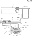
- each of the lock handles 55 includes a base plate 55a, a handle body (lock body) 55b, an operation knob (lock release operation element) 55c, a latch bolt 55d, a bolt case 55e, and an urging member 55f.
- the base plate 55a is a plate body formed by being bent in an L shape in a top view, and is fixed to a rear surface portion of the window plate 52a of the lower window portion 52.
- the handle body 55b is a cover body formed in an L shape in section in a top view and bulging rearward of a rear portion of the lower window portion 52, and is screwed and fixed to the base plate 55a to cover the entire base plate 55a.
- the operation knob 55c is provided at a side surface (inner side surface) of a bulging portion S1 of the handle body 55b near the center of the lower window portion 52.
- the two left and right operation knobs 55c are disposed at the left and right side edges 52c of the lower window portion 52 to face each other in the left-right direction.
- the latch bolt 55d is a shaft body extending in the left-right direction, and is held inside the bolt case 55e so as to be slidable in the left-right direction.
- a distal end claw portion J1 of the latch bolt 55d is formed in a substantially right-angle triangular shape in section in a top view, having an inclined surface at the front.
- the bolt case 55e is a tubular body extending in the left-right direction, and the latch bolt 55d is inserted into a hollow portion on the inner side of the bolt case 55e.
- the distal end claw portion J1 of the latch bolt 55d protrudes outward from an end portion (outer side end portion) of the bolt case 55d near the outer side of the lower window portion 52.
- a rear end portion J2 of the latch bolt 55d protrudes outward from an end portion (inner side end portion) of the bolt case 55d near the center of the lower window portion 52, and the operation knob 55c is attached to the rear end portion J2.
- the operation knob 55c is coupled to the latch bolt 55d at the side surface (inner side surface) of the bulging portion S1 of the handle body 55b near the center of the lower window portion 52.
- the urging member 55f is a coil spring, is annularly fitted on the outer periphery of the latch bolt 55d inside the bolt case 55e, and presses and urges the latch bolt 55d in the protruding direction of the distal end claw portion J1 (outward).
- the inclined surface of the distal end claw portion J1 of the latch bolt 55d is pressed against the lock receiver 39B as a result of that the lower window portion 52 is overlapped with the rear portion of the front frame 31, the distal end claw portion J1 is pushed to the inner side of the bolt case 55e against the elastic force of the urging member 55f.
- the fitting state of the lower window portion 52 to the lock receiver 39B is released, and the lower window portion 52 can be detached. Thereafter, when the hand is released from the operation knob 55c, the distal end claw portion J1 spontaneously returns to the state of protruding outward of the bolt case 55d by the elastic force of the urging member 55f.
- the pair of lock handles (locks) 55 are disposed on both the left and right side edges 52c of the lower window portion 52.
- the lock 55 may be disposed on only one of the left and right side edges 52c of the lower window portion 52 as long as the lower window portion 52 can be appropriately held with respect to the front frame (window frame) 31.
- the lock handle 55 is configured such that the fitting to the lock receiver 39B is released by the release operation of the operation knob (lock release operation element) 55c.
- the lock handle 55 may be configured not to include the operation knob 55c and such that the fitting to the lock receiver 39B is released by another operation such as lifting the lock handle 55.
- the lock release operation by the operation knob 55c that is the pulling operation of moving the operation knob 55c toward the center in the left-right direction of the lower window portion 52 has been described.
- the operation knob 55c may be provided at a rear portion of the handle body (lock body) 55b, and the above-described release operation may be an operation of moving the operation knob 55c rearward.
- the operation knob 55c may be provided at an upper portion of the handle body 55c, and the above-described release operation may be an operation of moving the operation knob 55c upward.
- the lock release operation element (operation knob) 55c provided at the lock handle 55 has been described.
- the lock release operation element 55c may be provided at the lock receiver 39B and may be configured such that the fitting between the lock handle 55 and the lock receiver 39B is released by a release operation of the lock release operation element 55c (for example, an operation of pushing the lock release operation element 55c toward the center in the left-right direction of the lower window portion 52).
- a cabin 5 is mounted on a working machine 1.
- the cabin 5 includes a protective frame 30 vertically provided around an operator's seat 6 included in the working machine 1; a roof 35 provided at an upper portion of the protective frame 30; and a front window 42 provided at a front portion of the protective frame 30.
- the front window 42 is vertically divided into an upper window portion 51, which is coupled to a window frame (front frame) 31 at the front portion of the protective frame 30 so as to be movable toward a lower surface of the roof 35, and a lower window portion 52 detachably coupled to the window frame 31.
- the window frame 31 includes a lower window stay 39A to engage with and support a lower edge 52b of the lower window portion 52, and a lock receiver 39B to hold a side edge 52c of the lower window portion 52 in a closed position.
- the lower window portion 52 includes at least one lock (lock handle) 55 to be fitted to the lock receiver 39B when the side edge 52c of the lower window portion 52 is overlapped with the window frame 31.
- the front window 42 can be fully opened by opening the upper window portion 51 toward the lower surface of the roof 35 (the inner upper side of the cabin 5), releasing the fitting state between the lock 55 and the lock receiver 39B, and detaching the lower window portion 52 from the window frame 31.
- the lower window portion 52 is detachable and openable as described above, it is not necessary to secure a space for accommodating the lower window portion 52 and the members belonging thereto near the lower surface (ceiling portion) of the roof 35. Hence the head clearance in the cabin 5 can be increased by that amount.
- the lower window portion 52 can be detached from the window frame 31 by tilting the lower window portion 52 forward/backward with the lower edge 52b serving as a fulcrum, and hence the front window 42 can be fully opened more easily than in a configuration in which the lower window portion is detached by sliding the lower window portion upward/downward along the window frame.
- the at least one lock 55 includes a plurality of locks 55 disposed on both left and right side edges 52c of the lower window portion 52. According to this configuration, it is not necessary to provide another structure such as a locking mechanism or a frame between the upper window portion 51 and the lower window portion 52, it is possible to adopt a structure in which the entire window frame 31 is largely opened when the front window 42 is fully opened.
- the lock 55 or the lock receiver 39B includes a lock release operation element (operation knob) 55c to manually release fitting between the lock 55 and the lock receiver 39B, such that the fitting between the lock 55 and the lock receiver 39B is released by a release operation of the lock release operation element 55c.
- operation knob operation knob
- the lower window portion 52 can be easily detached from the window frame 31 by the lock release operation element 55c being operated, and thus the front window 42 can be fully opened more quickly and easily.
- the lock 55 includes a lock body (handle body) 55b to support the lock release operation element 55c.
- the lock body 55b is provided to bulge rearward on a rear portion of the lower window portion 52. According to this configuration, when the lower window portion 52 is detached from the window frame 31 by the lock release operation element 55c being operated, the lower window portion 52 can be lifted by the lock body 55b being gripped. Hence the front window 42 can be fully opened more quickly and easily.
- the lock release operation element 55c is provided at a side portion of the lock body 55b near a center in a left-right direction of the lower window portion 52.
- the release operation is a pulling operation of moving the lock release operation element 55c toward the center in the left-right direction of the lower window portion 52.
- the direction in which the lock release operation element 55c is operated is different from the direction in which the lower window portion 52 is lifted and detached from the window frame 31, and hence it is possible to prevent or reduce unintentional detachment of the lower window portion 52 from the window frame 31 during cleaning or another work.
- the lower window portion 52 includes at least one first cutout 56 to engage with the lower window stay 39A and to inhibit the lower window portion 52 from moving in a left-right direction.
- the lower window portion 52 is positioned and held by the window frame 31 by the first cutout 56 being engaged with the lower window stay 39A, and hence the front window 42 can be fully closed quickly and easily.
- the opening/closing operability is also markedly improved.
- the at least one first cutout 56 includes a pair of first cutouts 56 disposed in the lower edge 52b of the lower window portion 52 to be spaced apart in the left-right direction. According to this configuration, the lower window portion 52 is appropriately positioned and held by the window frame 31, and hence the front window 42 can be fully closed more quickly and easily. Thus, the opening/closing operability is further improved.
- the cabin 5 includes a wiper 36 to wipe an outer surface of the upper window portion 51.
- the wiper 36 includes a blade 36a in contact with the outer surface, an arm 36b to support the blade 36a slidably along the outer surface, and a wiper drive (wiper drive unit) 36c to swing the arm 36b.
- the wiper drive 36c is provided on the window frame 31, at a position close to an outside of the window frame 31 in the left-right direction.
- the wiper drive 36c is provided on the upper window portion 51, it is necessary to secure a space capable of accommodating the wiper drive 36c between the upper window portion 51 in the open position and the lower surface portion of the roof 35, to avoid the wiper drive 36c from interfering with the roof 35 when the upper window portion 51 is opened toward the lower surface of the roof 35 (the inner upper side of the cabin 5). Accordingly, the head clearance in the cabin 5 is decreased by that amount.
- the wiper drive 36c is provided on the lower window portion 52, it is difficult to configure the lower window portion 52 to be detachable due to problems such as electrical wiring and weight, and thus, it is not possible to configure the front window 42 to be fully openable.
- the wiper drive 36c is provided on the window frame 31, at the position close to the outside of the window frame 31 in the left-right direction, and hence the lower window portion 52 can be easily detached from the window frame 31.
- the front window 42 can be easily fully opened. Also, with this configuration, it is not necessary to secure the space capable of accommodating the wiper drive 36c between the upper window portion 51 in the open position and the lower surface portion of the roof 35, and hence the head clearance in the cabin 5 can be increased by that amount.
- the wiper drive 36c is provided on the window frame 31, at a position lower than the upper window portion 51. According to this configuration, the wiper drive 36c is less likely to obstruct the field of view through the upper window portion 51, and hence the visibility of the front of the machine body (turning base) 2 for the operator is improved.
- the window frame 31 includes a wiper bracket 37 to support the wiper drive 36c.
- An upper edge 37d of the wiper bracket 37 is aligned in the left-right direction with an upper edge 52d of the lower window portion 52 when in the closed position, and is provided as an abutting end portion to abut against a lower edge 51F of the upper window portion 51.
- the wiper bracket 37 includes a drive cover 37C to cover the wiper drive 36c.
- the lower window portion 52 includes a second cutout 57 to avoid interference with the drive cover 37C when the lower window portion 52 is attached to or detached from the window frame 31. According to this configuration, when the lower window portion 52 is attached to or detached from the window frame 31, interference with the drive cover 37C can be avoided, and hence the front window 42 can be fully opened more quickly and easily.
- the lock 55 is fitted to the lock receiver 39B by the side edge 52c being pressed against the window frame 31 from an inner side to an outer side of the cabin 5 in a state in which the lower edge 52b of the lower window portion 52 is supported by the lower window stay 39A.
- the lower window portion 52 can be attached to the window frame 31 so as to be tilted forward/backward with the lower edge 52b serving as a fulcrum, and thus the front window 42 can be easily fully closed.
- a working machine 1 of the present example embodiment includes a machine body (turning base) 2; a working device 4 provided at the machine body 2; and the cabin 5 configured as described above. According to this configuration, it is possible to provide a working machine in which it is possible to fully open the front window 42 while preventing or reducing a decrease in head clearance in the cabin 5.
- an application target of the present invention is not limited to the working machine such as a backhoe, and may be applied to a construction machine such as a wheel loader, a compact track loader, or a skid-steer loader, or may be applied to an agricultural machine such as a tractor, a combine, a rice transplanter, or a lawn mower.
Landscapes
- Engineering & Computer Science (AREA)
- Mechanical Engineering (AREA)
- Mining & Mineral Resources (AREA)
- Civil Engineering (AREA)
- General Engineering & Computer Science (AREA)
- Structural Engineering (AREA)
- Window Of Vehicle (AREA)
Abstract
To provide a cabin (5) mounted on a working machine (1), in which it is possible to make a cabin front window portion to be fully openable while preventing or reducing a decrease in head clearance in the cabin.
A cabin mounted on a working machine includes a protective frame (30) vertically provided around an operator's seat (6) included in the working machine; a roof (35) provided at an upper portion of the protective frame; and a front window (42) provided at a front portion of the protective frame. The front window is vertically divided into an upper window portion (51), which is coupled to a window frame (31) at the front portion of the protective frame so as to be movable toward a lower surface of the roof, and a lower window portion (52) detachably coupled to the window frame. The window frame includes a lower window stay (39A) to engage with and support a lower edge (52b) of the lower window portion, and a lock receiver (39B) to hold a side edge (52c) of the lower window portion in a closed position. The lower window portion includes at least one lock (55) to be fitted to the lock receiver when the side edge of the lower window portion is overlapped with the window frame.
Description
- The present invention relates to a cabin included in a working machine such as a backhoe, and a working machine including the cabin.
- Conventionally, a working machine disclosed in
PTL 1 is known. - In a turning working machine disclosed in
PTL 1, a front window of a cabin is configured to be divided into upper and lower portions, and a front window glass assembly (upper window portion) that is an upper half portion of the front window is configured to open toward a ceiling portion (upward of an operator's seat) along a rail portion of a cabin framework body surrounding the operator's seat. - PTL 1:
Japanese Unexamined Patent Application Publication No. 2001-158230 - In the cabin mounted on this type of working machine, the upper half portion (upper window portion) of the front window opens to the inner upper side of the cabin as described above, and it is conceivable that a lower half portion (lower window portion) of the front window is also openable/closable. However, when the lower window portion is configured to open toward the ceiling portion along the rail portion similarly to the upper window portion, it is necessary to provide a space, at the ceiling portion, for accommodating the upper window portion and the lower window portion in an open state and the members belonging to both window portions, and hence there is a problem that a head clearance in the cabin is decreased by that amount.
- The present invention is made to solve such a problem, and an object of the present invention is to make a cabin front window portion fully openable while preventing or reducing a decrease in head clearance in a cabin.
- The present invention employs the following technical means to attain the above-described object.
- A cabin according to an example embodiment of the present invention is a cabin mounted on a working machine. The cabin includes a protective frame vertically provided around an operator's seat included in the working machine; a roof provided at an upper portion of the protective frame; and a front window provided at a front portion of the protective frame. The front window is vertically divided into an upper window portion, which is coupled to a window frame at the front portion of the protective frame so as to be movable toward a lower surface of the roof, and a lower window portion detachably coupled to the window frame. The window frame includes a lower window stay to engage with and support a lower edge of the lower window portion, and a lock receiver to hold a side edge of the lower window portion in a closed position. The lower window portion includes at least one lock to be fitted to the lock receiver when the side edge of the lower window portion is overlapped with the window frame.
- The at least one lock may include a plurality of locks disposed on both left and right side edges of the lower window portion.
- The lock or the lock receiver may include a lock release operation element to manually release fitting between the lock and the lock receiver, such that the fitting between the lock and the lock receiver is released by a release operation of the lock release operation element.
- The lock may include a lock body to support the lock release operation element. The lock body may be provided on a rear portion of the lower window portion to bulge rearward.
- The lock release operation element may be provided at a side portion of the lock body near a center in a left-right direction of the lower window portion. The release operation may be a pulling operation of moving the lock release operation element toward the center in the left-right direction of the lower window portion.
- The lower window portion may include at least one first cutout to engage with the lower window stay and to inhibit the lower window portion from moving in a left-right direction.
- The at least one first cutout may include, on the lower edge of the lower window portion, a pair of first cutouts spaced apart from each other in the left-right direction.
- The cabin may include a wiper to wipe an outer surface of the upper window portion. The wiper may include a blade in contact with the outer surface, an arm to support the blade so as to be slidable along the outer surface, and a wiper drive to swing the arm. The wiper drive may be provided on the window frame, at a position close to an outside of the window frame in the left-right direction.
- The wiper drive may be provided on the window frame, at a position lower than the upper window portion.
- The window frame may include a wiper bracket to support the wiper drive. An upper edge of the wiper bracket may be aligned in the left-right direction with an upper edge of the lower window portion when in the closed position, and may be provided as an abutting end portion to abut against a lower edge of the upper window portion.
- The wiper bracket may include a drive cover to cover the wiper drive. The lower window portion may include a second cutout to avoid interference with the drive cover when the lower window portion is attached to or detached from the window frame.
- The lock may be fitted to the lock receiver by the side edge being pressed against the window frame from an inner side to an outer side of the cabin in a state in which the lower edge of the lower window portion is supported by the lower window stay.
- A working machine includes a machine body; a working device provided at the machine body; and the above-described cabin.
- According to the above-described cabin, it is possible to make the cabin front window portion fully openable while preventing or reducing a decrease in head clearance in the cabin.
-
- [
FIG. 1] FIG. 1 is a left front perspective view of a working machine. - [
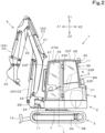
FIG. 2] FIG. 2 is a left side view of the working machine. - [
FIG. 3] FIG. 3 is a front view of the working machine. - [
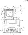
FIG. 4] FIG. 4 is a rear view of the working machine. - [
FIG. 5] FIG. 5 is a top view of a turning base. - [
FIG. 6] FIG. 6 is a right side view of the turning base. - [
FIG. 7] FIG. 7 is a rear view of a front frame and its surroundings. - [
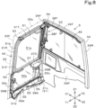
FIG. 8] FIG. 8 is a left rear perspective view of the front frame and a right frame, and their surroundings. - [
FIG. 9] FIG. 9 is a left rear perspective view of a window opening and its surroundings in a state in which a front window is open. - [
FIG. 10] FIG. 10 is a transverse sectional top view of a locking mechanism portion of a lower window portion and its surroundings. - Hereinafter, embodiments of the present invention will be described with reference to the drawings.
- As illustrated in
FIGS. 1 to 5 , aworking machine 1 of the present embodiment is a backhoe including a turning base (machine body) 2, atraveling device 3, and aworking device 4. Acabin 5 is mounted on theturning base 2. As illustrated inFIGS. 2 and5 , an operator'sseat 6 on which an operator is seated is provided inside thecabin 5. The workingmachine 1 is not limited to the backhoe, and may be a working machine of another type. - Hereinafter, a direction in which the operator seated on the operator's
seat 6 faces (a direction of arrow X1 inFIGS. 1 ,2 , and the like) is referred to as front or a forward side of theturning base 2, and a direction opposite thereto (a direction of arrow X2 inFIGS. 1 ,2 , and the like) is referred to as rear or a rearward side of theturning base 2. Also, the left side of the operator (a direction of arrow Y1 inFIGS. 3 ,4 , and the like) is referred to as left or a leftward side of theturning base 2, and the right side of the operator (a direction of arrow Y2 inFIGS. 3 ,4 , and the like) is referred to as right or a rightward side of theturning base 2. Further, the upper side of the operator (a direction of arrow Z1 inFIGS. 1 ,2 , and the like) is referred to as an upward side of theturning base 2 or above theturning base 2, and the lower side of the operator (a direction of arrow Z2 inFIGS. 1 ,2 , and the like) is referred to as a downward side of theturning base 2 or below theturning base 2. - As illustrated in
FIGS. 2 to 4 , the turning base (machine body) 2 is supported on an upper portion of thetraveling device 3 via a turning bearing 7 so as to be turnable in a left-right direction. In other words, theturning base 2 is supported so as to be rotatable about a turning axis (an axis extending in an up-down direction) L relative to thetraveling device 3. The turning axis L is the center of rotation of the turning bearing 7. - As illustrated in
FIG. 5 , a prime mover U1 is mounted in a rear portion of the inside of theturning base 2. The prime mover U1 is a diesel engine. Alternatively, the prime mover U1 may be a gasoline engine, may be an electric motor, or may be of a hybrid type including an engine and an electric motor. Additionally, a hydraulic pump U2 is connected to the prime mover U1. The hydraulic pump U2 is driven with power of the prime mover U1 and supplies a hydraulic fluid (pressure fluid) to hydraulic actuators such as a hydraulic motor (not illustrated) and a hydraulic cylinder 24 (described later) provided in the workingmachine 1. A compressor U3, a condenser U4, and a receiver U5 are mounted in a right portion of the inside of theturning base 2. The compressor U3, the condenser U4, and the receiver U5 are all devices constituting a portion of an air conditioning device (air conditioner) provided in the workingmachine 1. The compressor U3 is a device that compresses a refrigerant (air conditioner gas) into semi-liquid. The condenser U4 is a cooler that discharges heat of the refrigerant that has been semi-liquid in the compressor U3 to cool the refrigerant and to promote liquefaction. In the present embodiment, the condenser U4 is an electric condenser cooled by an electric fan. The receiver U5 is a device that stores the refrigerant liquefied in the condenser U4. - The turning
base 2 includes anexterior cover 8 that covers devices and components such as the prime mover U1, the hydraulic pump U2, the compressor U3, the condenser U4, and the receiver U5. Theexterior cover 8 includes a plurality of cover bodies. As illustrated inFIGS. 3 ,5 , and6 , theexterior cover 8 includes a condenser hood (front cover portion) 8A and a rightside portion hood 8B constituting a right front portion of theturning base 2. Thecondenser hood 8A is a cover that covers the condenser U4 and the receiver U5 from above. The rightside portion hood 8B is a cover that covers the condenser U4 and the receiver U5 from the right. Thecondenser hood 8A is detachably fixed to a fixing frame inside the turningbase 2, and the condenser U4 and the receiver U5 can be inspected and maintained when thecondenser hood 8A is detached. An air flow port E1 that is open forward of theturning base 2 is provided in a front lower portion of thecondenser hood 8A. The air heated through heat exchange with the refrigerant in the condenser U4 is discharged forward and downward of theturning base 2 from the air flow port E1. As illustrated inFIGS. 1 to 6 , the turningbase 2 includes at least onework lamp 11 that illuminates a surrounding area of theturning base 2. - As illustrated in
FIGS. 1 and2 , the travelingdevice 3 includes a travelingframe 3A and atraveling mechanism 3B. The traveling frame (track frame) 3A is a structure body to which thetraveling mechanism 3B is attached and that supports theturning base 2 from below. The travelingmechanism 3B is of, for example, a crawler type. Adozer 14 is attached to a front portion of the travelingdevice 3. The travelingdevice 3 is not limited to of the crawler type, and may be of a wheel type. - The working
device 4 is provided forward of theturning base 2 and is driven with the hydraulic fluid delivered from the hydraulic pump U2. The workingdevice 4 is coupled to asupport bracket 2A provided at a front portion of theturning base 2 via aswing bracket 2B. Theswing bracket 2B is pivotally supported by a front portion of thesupport bracket 2A so as to be swingable about a vertical axis (an axis extending in the up-down direction). - The working
device 4 includes aboom 21, anarm 22, and a bucket (working tool) 23. A proximal end portion of theboom 21 is pivotally supported by theswing bracket 2B so as to be swingable about a horizontal axis (an axis extending in the left-right direction). In other words, theboom 21 is pivotally coupled to theswing bracket 2B so as to be swingable in the up-down direction. A proximal end portion of thearm 22 is pivotally supported by a distal end portion of theboom 21 so as to be swingable about a horizontal axis (an axis extending in the left-right direction). In other words, thearm 22 is pivotally coupled to theboom 21 so as to be swingable in a front-rear direction and the up-down direction. A proximal end portion of thebucket 23 is pivotally supported by a distal end portion of thearm 22 so as to be swingable about a horizontal axis (an axis extending in the left-right direction). In other words, thebucket 23 is pivotally coupled to thearm 22 so as to be capable of performing shoveling and dumping. Instead of or in addition to thebucket 23, another working tool (hydraulic attachment) that can be driven with the hydraulic fluid can be attached to the workingmachine 1. Examples of the other working tool include a hydraulic breaker, a hydraulic crusher, an angle broom, an earth auger, a pallet fork, a sweeper, a mower, and a snow blower. - The working
device 4 is driven byhydraulic cylinders 24. Thehydraulic cylinders 24 include a swing cylinder C1, a boom cylinder C2, an arm cylinder C3, and a bucket cylinder C4. Theswing bracket 2B is swingable by extension/contraction of the swing cylinder C1. Theboom 21 is swingable by extension/contraction of the boom cylinder C2. Thearm 22 is swingable by extension/contraction of the arm cylinder C3. Thebucket 23 is capable of performing shoveling and dumping by extension/contraction of the bucket cylinder C4. As illustrated inFIGS. 3 and5 , the swing cylinder C1 is provided at a position close to the right of a lower portion of theturning base 2, and couples a machine body frame (not illustrated) of theturning base 2 and theswing bracket 2B. As illustrated inFIGS. 1 and2 , the boom cylinder C2 is provided at a proximal end portion of a lower surface of the boom 21 (a proximal end portion of a front surface of theboom 21 in a state of being raised upward), and couples theswing bracket 2B and theboom 21. The arm cylinder C3 is provided at a distal end portion of an upper surface of the boom 21 (a distal end portion of a rear surface of theboom 21 in the state of being raised upward), and couples theboom 21 and thearm 22. The bucket cylinder C4 is provided at an upper surface of the arm 22 (a front surface of thearm 22 in a state of being bent downward), and couples thearm 22 and thebucket 23. - As illustrated in
FIGS. 3 to 5 , thecabin 5 is disposed close to the left of the front portion of theturning base 2. In other words, the operator'sseat 6 is disposed close to the left of theturning base 2. As illustrated inFIGS. 1 and5 , thecabin 5 includes aprotective frame 30 that are vertically provided around the operator'sseat 6, and theprotective frame 30 includes afront frame 31 defining a front portion of thecabin 5, arear frame 32 defining a rear portion of thecabin 5, aleft frame 33 defining a left side portion of thecabin 5, and aright frame 34 defining a right side portion of thecabin 5. Additionally, aroof 35 defining an upper portion of thecabin 5 is provided at an upper portion of theprotective frame 30. - As illustrated in
FIGS. 1 and3 , the front frame (window frame) 31 is provided with awiper 36, awindow opening 41, afront window 42, and afront lamp bracket 43. As illustrated inFIG. 4 , therear frame 32 is provided with arear window 44 and arear lamp bracket 45. As illustrated inFIGS. 1 and2 , theleft frame 33 is provided with a ridingentrance 46, a ridingdoor 47, and a leftrear window 48. As illustrated inFIG. 5 , theright frame 34 is provided with aright window 49. As illustrated inFIG. 6 , theright frame 34 is provided with aright window 49. As illustrated inFIGS. 1 and5 , theroof 35 is provided with aroof window 50. - As illustrated in
FIG. 2 , theleft frame 33 includes a leftfront pillar 33F, a leftrear pillar 33R, acenter pillar 33C, a leftupper frame 33T, and aleft side panel 33P. The leftfront pillar 33F is vertically provided at a left front portion of thecabin 5. The leftrear pillar 33R is vertically provided at a left rear portion of thecabin 5. Thecenter pillar 33C is vertically provided between the leftfront pillar 33F and the leftrear pillar 33R. The leftupper frame 33T is laterally provided between upper ends of the leftfront pillar 33F and the leftrear pillar 33R. Theleft side panel 33P extends between lower portions of thecenter pillar 33C and the leftrear pillar 33R. The ridingentrance 46 is defined by the leftfront pillar 33F, thecenter pillar 33C, and the leftupper frame 33T. The ridingdoor 47 is pivotally coupled to thecenter pillar 33C by a hinge or the like, and covers and closes the ridingentrance 46 from the left. The leftrear window 48 is fitted in an opening defined by thecenter pillar 33C, the leftrear pillar 33R, the leftupper frame 33T, and theleft side panel 33P. Also, adoor window 47W is fitted in the ridingdoor 47 to occupy a substantially entire surface of the ridingdoor 47. Therefore, the leftrear window 48 and thedoor window 47W secure a left field of view of the operator. - As illustrated in
FIG. 6 , theright frame 34 includes a rightfront pillar 34F, a rightrear pillar 34R, and a rightupper frame 34T. The rightfront pillar 34F is vertically provided at a right front portion of thecabin 5. The rightrear pillar 34R is vertically provided at a right rear portion of thecabin 5. The rightupper frame 34T is laterally provided between upper ends of the rightfront pillar 34F and the rightrear pillar 34R. Aright side panel 34P is fitted into a region surrounded by the rightfront pillar 34F, the rightrear pillar 34R, and the rightupper frame 34T to occupy the substantially entire region. Theright window 49 is fitted in an opening formed in theright side panel 34P, and secures a right field of view of the operator. - As illustrated in
FIG. 3 , thefront frame 31 includes a leftwindow frame portion 31a, a rightwindow frame portion 31b, a lowerwindow frame portion 31c, and a frontlower frame 31d. The leftwindow frame portion 31a extends in the up-down direction along the leftfront pillar 33F. The rightwindow frame portion 31b extends in the up-down direction along the rightfront pillar 34F. The lowerwindow frame portion 31c couples and supports lower ends of the leftwindow frame portion 31a and the rightwindow frame portion 31b. The frontlower frame 31d is laterally provided between lower ends of the leftfront pillar 33F and the rightfront pillar 34F along a lower edge of the lowerwindow frame portion 31c. Additionally, awiper bracket 37 is connected to a right side edge of the lowerwindow frame portion 31c (an inner right side edge of the window opening 41). Thewindow opening 41 is defined in a substantially rectangular shape long in the up-down direction by the leftwindow frame portion 31a, the rightwindow frame portion 31b, the lowerwindow frame portion 31d, and afront edge 35a of theroof 35. Thewiper 36 is pivotally coupled to thewiper bracket 37 so as to be swingable. Thefront lamp bracket 43 is provided on a front surface portion of the frontlower frame 31d. Thefront lamp bracket 43 is provided withwork lamps 11 that illuminate the front and the left of theturning base 2. - As illustrated in
FIG. 4 , therear frame 32 includes a rearupper frame 32a and a rearlower frame 32b. The rearupper frame 32a is laterally provided between the upper ends of the leftrear pillar 33R and the rightrear pillar 34R at a rear upper portion of thecabin 5. The rearlower frame 32b is located forward of acover body 8R (a cover that covers a main body of the air conditioner mounted in the rear portion of the cabin 5) provided at the rear portion of thecabin 5, and is laterally provided between lower ends of the leftrear pillar 33R and the rightrear pillar 34R. Therear window 44 is fitted in an opening defined by the leftrear pillar 33R, the rightrear pillar 34R, the rearupper frame 32a, and the rearlower frame 32b, and secures a rear field of view of the operator. Therear lamp bracket 45 is provided on a rear surface portion of the rearupper frame 32a. Therear lamp bracket 45 is provided withwork lamps 11 that illuminate the rear and the left and right of theturning base 2. - As illustrated in
FIG. 5 , theroof 35 is laterally provided between the leftupper frame 33T and the rightupper frame 34T, and covers the operator'sseat 6 from above. Thefront edge 35a of theroof 35 extends to overlap the front portion of thecabin 5. In other words, thefront edge 35a of theroof 35 defines an upper frame that is laterally provided between the upper ends of the leftfront pillar 33F and the rightfront pillar 34F at a front upper portion of thecabin 5. The left and rightwindow frame portions front frame 31 are connected to left and right lower end portions of thefront edge 35a. Theroof window 50 is provided at a position close to thefront edge 35a of theroof 35, and secures a front upper field of view of the operator. - As illustrated in
FIGS. 3 and7 , thewiper 36 includes ablade 36a, a pair ofarms 36b, and a wiper drive unit (wiper drive) 36c. Thewiper drive unit 36c is a device that swings thearms 36b by a wiper motor and a link mechanism (not illustrated), and is fixed to a rear surface portion of thewiper bracket 37. Also, thewiper drive unit 36c is entirely covered by adrive cover 37C provided on the rear surface portion of thewiper bracket 37. Proximal end portions of thearms 36b are pivotally coupled to thewiper drive unit 36c from a front surface of thewiper bracket 37. The proximal end portions of the twoarms 36b are coupled to the front surface of thewiper bracket 37 to be laterally arranged in the left-right direction. Distal end portions of the twoarms 36b are coupled to each other to be laterally arranged in the left-right direction by acoupling plate 36d. Theblade 36a is coupled to and supported by the distal end portions of thearms 36b via thecoupling plate 36d. Theblade 36a extends in the up-down direction in a position close to the rightwindow frame portion 31b on the front side of thewindow opening 41 in a stopped state (seeFIG. 3 ). Also, when thearms 36b are swung leftward from this state, theblade 36a slides leftward and slightly obliquely downward along a front surface (outer surface) of anupper window portion 51 of thefront window 42 in a state in which a blade end is in contact with the front surface of theupper window portion 51. In the present embodiment, thewiper 36 is a double-arm type (pantograph type) wiper device that swings theblade 36a by the twoarms 36b. However, thewiper 36 may be a single-arm type wiper device that swings theblade 36a by onearm 36b. - In the case of the above-described double-arm type wiper device, when the
wiper drive unit 36c serving as the proximal end is disposed too far on the outer side with respect to the central position in the left-right direction of theupper window portion 51, theblade 36a cannot be swung in a wide range along the front surface of theupper window portion 51, and the unwiped area increases. However, in the workingmachine 1 of the present embodiment, thewiper bracket 37 is provided to protrude from the right side edge of the lowerwindow frame portion 31c toward the center in the left-right direction of theupper window portion 51, and thewiper drive unit 36c is provided on thewiper bracket 37. Accordingly, theblade 36a can be swung in a wider range along the front surface of theupper window portion 51. - The
wiper bracket 37 is provided on the right side edge of the lowerwindow frame portion 31c, at a position lower than theupper window portion 51. Also, thewiper bracket 37 is disposed on the right side edge of the lowerwindow frame portion 31c, at a position located in substantially the same direction as the line of sight of the operator seated on the operator'sseat 6 when the operator views theswing bracket 2B and lower than the height of the line of sight, in other words, at a position at which thewiper bracket 37 is seen overlapping theswing bracket 2B in the front-rear direction (seeFIG. 3 ). Accordingly, thewiper bracket 37 and thewiper drive 36c are less likely to obstruct the field of view through theupper window portion 51, and hence the visibility of the front of the machine body (turning base) 2 for the operator is improved. - The
front window 42 has an outer peripheral shape substantially the same as the shape of thewindow opening 41, and covers and closes the window opening 41 from the rear (the inner side of the cabin 5). Thefront window 42 includes anupper window portion 51 that covers and closes an upper half portion of thewindow opening 41, and alower window portion 52 that covers and closes a lower half portion of thewindow opening 41. In this way, thefront window 42 is divided into upper and lower portions. In the present embodiment, theupper window portion 51 is formed to have a size to cover and close a range of approximately upper three-fifths of thewindow opening 41, and thelower window portion 52 is formed to have a size to cover and close a range of approximately lower two-fifths of thewindow opening 41. However, the proportions of the ranges of thewindow opening 41 covered and closed by theupper window portion 51 and thelower window portion 52 are not limited to the above-described proportions. - As illustrated in
FIGS. 7 and8 , theupper window portion 51 includes awindow plate 51a, an outerperipheral frame 51b, and at least oneslider 54. Thewindow plate 51a is formed of a transparent plate material such as glass or synthetic resin. The outerperipheral frame 51b extends along the outer periphery of thewindow plate 51a and holds thewindow plate 51a. The at least oneslider 54 includessliders 54 disposed at left and right side end portions of an upper edge (upper window upper edge) 51T and left and right side edges of a lower edge (upper window lower edge) 51F of the outerperipheral frame 51b. - The
sliders 54 near the upper windowupper edge 51T are engaged with and held by upper portion rails 38T extending in the front-rear direction along positions close to left and right side edges of a lower surface of theroof 35. In contrast, thesliders 54 near the upper windowlower edge 51F are engaged with and held by front portion rails 38F extending in the up-down direction along inner side surfaces of the left and rightfront pillars upper edge 51T of theupper window portion 51 is engaged and held so as to be slidable in the front-rear direction at a lower surface portion of theroof 35, and thelower edge 51F of theupper window portion 51 is engaged and held so as to be slidable in the up-down direction at inner side portions of thefront pillars upper window portion 51 is coupled and supported on the inner side of theright frame 34 via alink mechanism 53. Accordingly, theupper window portion 51 can be moved from a closed position arranged at a rear portion of thefront frame 31 to an open position arranged at a lower portion of the roof 35 (the inner upper side of the cabin 5) by changing its posture from a raised state to a tilted state as theupper window portion 51 is lifted upward (seeFIG. 9 ). - As illustrated in
FIGS. 7 to 9 , thelower window portion 52 includes awindow plate 52a and at least one lock handle (lock) 55. Thewindow plate 52a is formed of a transparent plate material such as glass or synthetic resin. Thewindow plate 52a includes at least onefirst cutout 56 and asecond cutout 57. The at least one cutout includes a pair offirst cutouts 56 provided in alower edge 52b of thelower window portion 52 to be spaced apart in the left-right direction. Thefirst cutouts 56 are formed in rectangular U-shapes recessed toward the upper side of thewindow plate 52a, and are engaged from above with a pair of lower window stays 39A provided at a rear portion of the lowerwindow frame portion 31c, at positions lower than thewindow opening 41 to be spaced apart in the right-left direction. Accordingly, thelower edge 52b of thelower window portion 52 is positioned and held at a rear portion of thewindow opening 41. Thesecond cutout 57 is provided at an upper end position of aright side edge 52c of thelower window portion 52, in other words, in an upper right corner portion of thelower window portion 52. Thesecond cutout 57 is formed in a substantially arc shape recessed toward the lower left of thewindow plate 52a, and is disposed along a lower left outer peripheral surface of thedrive cover 37C of thewiper drive unit 36c. Accordingly, interference of thelower window portion 52 with thedrive cover 37C is avoided when thelower window portion 52 is attached to or detached from the front frame (window frame) 31. When thelower window portion 52 is in the closed position, anupper edge 52d of thelower window portion 52 is arranged to be aligned with anupper edge 37d of thewiper bracket 37 in the left-right direction. In other words, theupper edge 37d of thewiper bracket 37 is provided at a position aligned in the left-right direction with theupper edge 52d of thelower window portion 52 in the closed position, and serves as an abutting end portion with respect to the upper windowlower edge 51F when theupper window portion 51 is closed. Also, thewiper drive unit 36c fixed to the rear surface portion of thewiper bracket 37 is disposed on thefront frame 31, at a position lower than theupper window portion 51. - The at least one lock handle 55 includes lock handles 55 disposed on left and right side edges 52c of a rear surface portion of the
lower window portion 52. The two lock handles 55 are arranged at the same height position at the center in the up-down direction on the rear surface portion of thelower window portion 52. The lock handles 55 are configured to be fitted to a pair oflock receivers 39B provided on the rear portion of the lowerwindow frame portion 31c, at positions located leftward and rightward of thewindow opening 41, and the left and right side edges 52c of thelower window portion 52 are fixed at the rear portion of thewindow opening 41 by the lock handles 55 being fitted to thelock receivers 39B. - As described above, the
lower edge 52b of thelower window portion 52 is engaged with and held by the two lower window stays 39A, and the left and right side edges 52c are detachably fitted to and held by the twolock receivers 39B. Thus, after the fitting of the left and right lock handles 55 to thelock receivers 39B is released, by raising theupper edge 52d in a state of being slightly tilted rearward, thelower window portion 52 can be detached from thefront frame 31 without interfering with thedrive cover 37C. In contrast, after thelower edge 52d is engaged with the lower window stays 39A in a posture in which theupper edge 52d is slightly tilted rearward, by overlapping thelower window portion 52 with the rear portion of thefront frame 31 so as to cover the window opening 41 from the rear, and by fitting the left and right lock handles 55 to thelock receivers 39B, thelower window portion 52 can be fixed to and held at the rear portion of thefront frame 31 without interfering with thedrive cover 37C. Agasket 31P is provided along the entire inner peripheral edge of thewindow opening 41, and theupper window portion 51 and thelower window portion 52 in the closed position are both held in close contact at the rear portion of thefront frame 31 via thegasket 31P. - As illustrated in
FIG. 10 , each of the lock handles 55 includes abase plate 55a, a handle body (lock body) 55b, an operation knob (lock release operation element) 55c, alatch bolt 55d, abolt case 55e, and an urgingmember 55f. Thebase plate 55a is a plate body formed by being bent in an L shape in a top view, and is fixed to a rear surface portion of thewindow plate 52a of thelower window portion 52. Thehandle body 55b is a cover body formed in an L shape in section in a top view and bulging rearward of a rear portion of thelower window portion 52, and is screwed and fixed to thebase plate 55a to cover theentire base plate 55a. Theoperation knob 55c is provided at a side surface (inner side surface) of a bulging portion S1 of thehandle body 55b near the center of thelower window portion 52. In other words, the two left and right operation knobs 55c are disposed at the left and right side edges 52c of thelower window portion 52 to face each other in the left-right direction. - The
latch bolt 55d is a shaft body extending in the left-right direction, and is held inside thebolt case 55e so as to be slidable in the left-right direction. A distal end claw portion J1 of thelatch bolt 55d is formed in a substantially right-angle triangular shape in section in a top view, having an inclined surface at the front. Thebolt case 55e is a tubular body extending in the left-right direction, and thelatch bolt 55d is inserted into a hollow portion on the inner side of thebolt case 55e. The distal end claw portion J1 of thelatch bolt 55d protrudes outward from an end portion (outer side end portion) of thebolt case 55d near the outer side of thelower window portion 52. A rear end portion J2 of thelatch bolt 55d protrudes outward from an end portion (inner side end portion) of thebolt case 55d near the center of thelower window portion 52, and theoperation knob 55c is attached to the rear end portion J2. In other words, theoperation knob 55c is coupled to thelatch bolt 55d at the side surface (inner side surface) of the bulging portion S1 of thehandle body 55b near the center of thelower window portion 52. - The urging
member 55f is a coil spring, is annularly fitted on the outer periphery of thelatch bolt 55d inside thebolt case 55e, and presses and urges thelatch bolt 55d in the protruding direction of the distal end claw portion J1 (outward). Thus, when the inclined surface of the distal end claw portion J1 of thelatch bolt 55d is pressed against thelock receiver 39B as a result of that thelower window portion 52 is overlapped with the rear portion of thefront frame 31, the distal end claw portion J1 is pushed to the inner side of thebolt case 55e against the elastic force of the urgingmember 55f. Then, when the distal end claw portion J1 of thelatch bolt 55d overlaps a latch fitting hole H1 of thelock receiver 39B as a result of that thelower window portion 52 is further pushed toward the rear portion of thefront frame 31, the distal end claw portion J1 is spontaneously fitted into the latch fitting hole H1 by the elastic force of the urgingmember 55f. Accordingly, thelower window portion 52 is fixed to and held at the rear portion of thefront frame 31. Also, when theoperation knob 55c is pulled by hand from this state toward the center of thelower window portion 52 against the elastic force of the urgingmember 55f (release operation), the distal end claw portion J1 of thelatch bolt 55d is drawn to the inner side of thebolt case 55e in conjunction with the operation of theoperation knob 55c. Accordingly, the fitting state of thelower window portion 52 to thelock receiver 39B is released, and thelower window portion 52 can be detached. Thereafter, when the hand is released from theoperation knob 55c, the distal end claw portion J1 spontaneously returns to the state of protruding outward of thebolt case 55d by the elastic force of the urgingmember 55f. - In the above-described embodiment, the pair of lock handles (locks) 55 are disposed on both the left and right side edges 52c of the
lower window portion 52. However, thelock 55 may be disposed on only one of the left and right side edges 52c of thelower window portion 52 as long as thelower window portion 52 can be appropriately held with respect to the front frame (window frame) 31. - Also, in the above-described embodiment, the lock handle 55 is configured such that the fitting to the
lock receiver 39B is released by the release operation of the operation knob (lock release operation element) 55c. However, the lock handle 55 may be configured not to include theoperation knob 55c and such that the fitting to thelock receiver 39B is released by another operation such as lifting thelock handle 55. - Also, in the above-described embodiment, the lock release operation by the
operation knob 55c that is the pulling operation of moving theoperation knob 55c toward the center in the left-right direction of thelower window portion 52 has been described. However, theoperation knob 55c may be provided at a rear portion of the handle body (lock body) 55b, and the above-described release operation may be an operation of moving theoperation knob 55c rearward. Alternatively, theoperation knob 55c may be provided at an upper portion of thehandle body 55c, and the above-described release operation may be an operation of moving theoperation knob 55c upward. Also, the above-described release operation is not limited to the pulling operation, and may be a pushing operation, a sliding operation, a swinging operation, or a rotating operation as long as the fitting state between the lock handle 55 and thelock receiver 39B can be smoothly and safely released. - Also, in the above-described embodiment, the lock release operation element (operation knob) 55c provided at the lock handle 55 has been described. However, the lock
release operation element 55c may be provided at thelock receiver 39B and may be configured such that the fitting between the lock handle 55 and thelock receiver 39B is released by a release operation of the lockrelease operation element 55c (for example, an operation of pushing the lockrelease operation element 55c toward the center in the left-right direction of the lower window portion 52). - As described above, in the present example embodiment, a
cabin 5 is mounted on a workingmachine 1. Thecabin 5 includes aprotective frame 30 vertically provided around an operator'sseat 6 included in the workingmachine 1; aroof 35 provided at an upper portion of theprotective frame 30; and afront window 42 provided at a front portion of theprotective frame 30. Thefront window 42 is vertically divided into anupper window portion 51, which is coupled to a window frame (front frame) 31 at the front portion of theprotective frame 30 so as to be movable toward a lower surface of theroof 35, and alower window portion 52 detachably coupled to thewindow frame 31. Thewindow frame 31 includes a lower window stay 39A to engage with and support alower edge 52b of thelower window portion 52, and alock receiver 39B to hold aside edge 52c of thelower window portion 52 in a closed position. Thelower window portion 52 includes at least one lock (lock handle) 55 to be fitted to thelock receiver 39B when theside edge 52c of thelower window portion 52 is overlapped with thewindow frame 31. - According to this configuration, the
front window 42 can be fully opened by opening theupper window portion 51 toward the lower surface of the roof 35 (the inner upper side of the cabin 5), releasing the fitting state between thelock 55 and thelock receiver 39B, and detaching thelower window portion 52 from thewindow frame 31. Moreover, since thelower window portion 52 is detachable and openable as described above, it is not necessary to secure a space for accommodating thelower window portion 52 and the members belonging thereto near the lower surface (ceiling portion) of theroof 35. Hence the head clearance in thecabin 5 can be increased by that amount. Moreover, thelower window portion 52 can be detached from thewindow frame 31 by tilting thelower window portion 52 forward/backward with thelower edge 52b serving as a fulcrum, and hence thefront window 42 can be fully opened more easily than in a configuration in which the lower window portion is detached by sliding the lower window portion upward/downward along the window frame. - Also, the at least one
lock 55 includes a plurality oflocks 55 disposed on both left and right side edges 52c of thelower window portion 52. According to this configuration, it is not necessary to provide another structure such as a locking mechanism or a frame between theupper window portion 51 and thelower window portion 52, it is possible to adopt a structure in which theentire window frame 31 is largely opened when thefront window 42 is fully opened. - Additionally, the
lock 55 or thelock receiver 39B includes a lock release operation element (operation knob) 55c to manually release fitting between thelock 55 and thelock receiver 39B, such that the fitting between thelock 55 and thelock receiver 39B is released by a release operation of the lockrelease operation element 55c. According to this configuration, thelower window portion 52 can be easily detached from thewindow frame 31 by the lockrelease operation element 55c being operated, and thus thefront window 42 can be fully opened more quickly and easily. - Additionally, the
lock 55 includes a lock body (handle body) 55b to support the lockrelease operation element 55c. Thelock body 55b is provided to bulge rearward on a rear portion of thelower window portion 52. According to this configuration, when thelower window portion 52 is detached from thewindow frame 31 by the lockrelease operation element 55c being operated, thelower window portion 52 can be lifted by thelock body 55b being gripped. Hence thefront window 42 can be fully opened more quickly and easily. - Also, the lock
release operation element 55c is provided at a side portion of thelock body 55b near a center in a left-right direction of thelower window portion 52. The release operation is a pulling operation of moving the lockrelease operation element 55c toward the center in the left-right direction of thelower window portion 52. According to this configuration, the direction in which the lockrelease operation element 55c is operated is different from the direction in which thelower window portion 52 is lifted and detached from thewindow frame 31, and hence it is possible to prevent or reduce unintentional detachment of thelower window portion 52 from thewindow frame 31 during cleaning or another work. - Also, the
lower window portion 52 includes at least onefirst cutout 56 to engage with the lower window stay 39A and to inhibit thelower window portion 52 from moving in a left-right direction. According to this configuration, thelower window portion 52 is positioned and held by thewindow frame 31 by thefirst cutout 56 being engaged with the lower window stay 39A, and hence thefront window 42 can be fully closed quickly and easily. Thus, the opening/closing operability is also markedly improved. - Also, the at least one
first cutout 56 includes a pair offirst cutouts 56 disposed in thelower edge 52b of thelower window portion 52 to be spaced apart in the left-right direction. According to this configuration, thelower window portion 52 is appropriately positioned and held by thewindow frame 31, and hence thefront window 42 can be fully closed more quickly and easily. Thus, the opening/closing operability is further improved. - Additionally, the
cabin 5 includes awiper 36 to wipe an outer surface of theupper window portion 51. Thewiper 36 includes ablade 36a in contact with the outer surface, anarm 36b to support theblade 36a slidably along the outer surface, and a wiper drive (wiper drive unit) 36c to swing thearm 36b. Thewiper drive 36c is provided on thewindow frame 31, at a position close to an outside of thewindow frame 31 in the left-right direction. - In the case where the
wiper drive 36c is provided on theupper window portion 51, it is necessary to secure a space capable of accommodating thewiper drive 36c between theupper window portion 51 in the open position and the lower surface portion of theroof 35, to avoid thewiper drive 36c from interfering with theroof 35 when theupper window portion 51 is opened toward the lower surface of the roof 35 (the inner upper side of the cabin 5). Accordingly, the head clearance in thecabin 5 is decreased by that amount. In the case where thewiper drive 36c is provided on thelower window portion 52, it is difficult to configure thelower window portion 52 to be detachable due to problems such as electrical wiring and weight, and thus, it is not possible to configure thefront window 42 to be fully openable. - In the
vehicle cabin 5 of the above-described example embodiment, thewiper drive 36c is provided on thewindow frame 31, at the position close to the outside of thewindow frame 31 in the left-right direction, and hence thelower window portion 52 can be easily detached from thewindow frame 31. In other words, thefront window 42 can be easily fully opened. Also, with this configuration, it is not necessary to secure the space capable of accommodating thewiper drive 36c between theupper window portion 51 in the open position and the lower surface portion of theroof 35, and hence the head clearance in thecabin 5 can be increased by that amount. - Also, the
wiper drive 36c is provided on thewindow frame 31, at a position lower than theupper window portion 51. According to this configuration, thewiper drive 36c is less likely to obstruct the field of view through theupper window portion 51, and hence the visibility of the front of the machine body (turning base) 2 for the operator is improved. - Additionally, the
window frame 31 includes awiper bracket 37 to support thewiper drive 36c. Anupper edge 37d of thewiper bracket 37 is aligned in the left-right direction with anupper edge 52d of thelower window portion 52 when in the closed position, and is provided as an abutting end portion to abut against alower edge 51F of theupper window portion 51. According to this configuration, it is not necessary to provide a frame between theupper window portion 51 and thelower window portion 52, and hence it is possible to adopt a structure in which theentire window frame 31 is largely opened when thefront window 42 is fully opened. Also, when thefront window 42 is fully closed, the sealing performance between theupper window portion 51 and thelower window portion 52 can be enhanced. - Additionally, the
wiper bracket 37 includes adrive cover 37C to cover thewiper drive 36c. Thelower window portion 52 includes asecond cutout 57 to avoid interference with thedrive cover 37C when thelower window portion 52 is attached to or detached from thewindow frame 31. According to this configuration, when thelower window portion 52 is attached to or detached from thewindow frame 31, interference with thedrive cover 37C can be avoided, and hence thefront window 42 can be fully opened more quickly and easily. - Also, the
lock 55 is fitted to thelock receiver 39B by theside edge 52c being pressed against thewindow frame 31 from an inner side to an outer side of thecabin 5 in a state in which thelower edge 52b of thelower window portion 52 is supported by the lower window stay 39A. According to this configuration, thelower window portion 52 can be attached to thewindow frame 31 so as to be tilted forward/backward with thelower edge 52b serving as a fulcrum, and thus thefront window 42 can be easily fully closed. - Also, a working
machine 1 of the present example embodiment includes a machine body (turning base) 2; a workingdevice 4 provided at themachine body 2; and thecabin 5 configured as described above. According to this configuration, it is possible to provide a working machine in which it is possible to fully open thefront window 42 while preventing or reducing a decrease in head clearance in thecabin 5. - While the present invention has been described above, it should be understood that the embodiments disclosed herein are examples in all points and are not restrictive. The scope of the present invention is defined not by the above description but by the claims, and is intended to include all modifications within the meaning and scope equivalent to the claims.
- Also, in the above-described embodiments, the example has been described in which the present invention is applied to the working machine such as a backhoe. However, an application target of the present invention is not limited to the working machine such as a backhoe, and may be applied to a construction machine such as a wheel loader, a compact track loader, or a skid-steer loader, or may be applied to an agricultural machine such as a tractor, a combine, a rice transplanter, or a lawn mower.
-
- 1
- working machine
- 2
- turning base (machine body)
- 3
- traveling device
- 4
- working device
- 5
- cabin
- 6
- operator's seat
- 30
- protective frame
- 31
- front frame (window frame)
- 35
- roof
- 36
- wiper
- 36a
- blade
- 36b
- arm
- 36c
- wiper drive unit (wiper drive)
- 37
- wiper bracket
- 37C
- drive cover
- 39A
- lower window stay
- 39B
- lock receiver
- 42
- front window
- 51
- upper window portion
- 52
- lower window portion
- 52b
- lower edge
- 52c
- side edge
- 55
- lock
- 55b
- handle body (lock body)
- 55c
- operation knob (lock release operation element)
- 56
- first cutout
- 57
- second cutout
Claims (13)
- A cabin mounted on a working machine, comprising:a protective frame vertically provided around an operator's seat included in the working machine;a roof provided at an upper portion of the protective frame; anda front window provided at a front portion of the protective frame, whereinthe front window is vertically divided into an upper window portion, which is coupled to a window frame at the front portion of the protective frame so as to be movable toward a lower surface of the roof, and a lower window portion detachably coupled to the window frame,the window frame includes a lower window stay to engage with and support a lower edge of the lower window portion, and a lock receiver to hold a side edge of the lower window portion in a closed position, andthe lower window portion includes at least one lock to be fitted to the lock receiver when the side edge of the lower window portion is overlapped with the window frame.
- The cabin according to claim 1, wherein the at least one lock includes a plurality of locks disposed on both left and right side edges of the lower window portion.
- The cabin according to claim 2, wherein the lock or the lock receiver includes a lock release operation element to manually release fitting between the lock and the lock receiver, such that the fitting between the lock and the lock receiver is released by a release operation of the lock release operation element.
- The cabin according to claim 3, whereinthe lock includes a lock body to support the lock release operation element, andthe lock body is provided on a rear portion of the lower window portion to bulge rearward.
- The cabin according to claim 4, whereinthe lock release operation element is provided at a side portion of the lock body near a center in a left-right direction of the lower window portion, andthe release operation is a pulling operation of moving the lock release operation element toward the center in the left-right direction of the lower window portion.
- The cabin according to claim 1, wherein the lower window portion includes at least one first cutout to engage with the lower window stay and to inhibit the lower window portion from moving in a left-right direction.
- The cabin according to claim 6, wherein the at least one first cutout includes, on the lower edge of the lower window portion, a pair of first cutouts spaced apart from each other in the left-right direction.
- The cabin according to claim 1, comprising:a wiper to wipe an outer surface of the upper window portion, whereinthe wiper includes a blade in contact with the outer surface, an arm to support the blade slidably along the outer surface, and a wiper drive to swing the arm, andthe wiper drive is provided on the window frame, at a position close to an outside of the window frame in the left-right direction.
- The cabin according to claim 8, wherein the wiper drive is provided on the window frame, at a position lower than the upper window portion.
- The cabin according to claim 9, whereinthe window frame includes a wiper bracket to support the wiper drive, andan upper edge of the wiper bracket is aligned in the left-right direction with an upper edge of the lower window portion when in the closed position and is provided as an abutting end portion to abut against a lower edge of the upper window portion.
- The cabin according to claim 10, whereinthe wiper bracket includes a drive cover to cover the wiper drive, andthe lower window portion includes a second cutout to avoid interference with the drive cover when the lower window portion is attached to or detached from the window frame.
- The cabin according to claim 1, wherein the lock is fitted to the lock receiver by the side edge being pressed against the window frame from an inner side to an outer side of the cabin in a state in which the lower edge of the lower window portion is supported by the lower window stay.
- A working machine comprising:a machine body;a working device provided on the machine body; andthe cabin according to any one of claims 1 to 12.
Applications Claiming Priority (2)
| Application Number | Priority Date | Filing Date | Title |
|---|---|---|---|
| JP2022105776 | 2022-06-30 | ||
| PCT/JP2023/023123 WO2024004818A1 (en) | 2022-06-30 | 2023-06-22 | Cabin and work machine |
Publications (1)
| Publication Number | Publication Date |
|---|---|
| EP4549668A1 true EP4549668A1 (en) | 2025-05-07 |
Family
ID=89382905
Family Applications (1)
| Application Number | Title | Priority Date | Filing Date |
|---|---|---|---|
| EP23831262.3A Pending EP4549668A1 (en) | 2022-06-30 | 2023-06-22 | Cabin and work machine |
Country Status (4)
| Country | Link |
|---|---|
| US (1) | US20250101712A1 (en) |
| EP (1) | EP4549668A1 (en) |
| JP (1) | JP7843845B2 (en) |
| WO (1) | WO2024004818A1 (en) |
Families Citing this family (1)
| Publication number | Priority date | Publication date | Assignee | Title |
|---|---|---|---|---|
| JP2025171325A (en) * | 2024-05-09 | 2025-11-20 | ヤンマーホールディングス株式会社 | Work machine |
Family Cites Families (16)
| Publication number | Priority date | Publication date | Assignee | Title |
|---|---|---|---|---|
| JPS5869559U (en) * | 1981-11-06 | 1983-05-11 | 井関農機株式会社 | Tractor cabin wiper |
| JP2539121Y2 (en) | 1991-05-30 | 1997-06-25 | 株式会社小松製作所 | Front window of cab of construction machinery |
| JP2583667Y2 (en) * | 1993-06-14 | 1998-10-27 | 油谷重工株式会社 | Cab window structure |
| JP3499758B2 (en) | 1998-09-25 | 2004-02-23 | 株式会社クボタ | Cabin front window device |
| JP2000096624A (en) | 1998-09-25 | 2000-04-04 | Kubota Corp | Turning work machine |
| JP4079298B2 (en) | 1999-05-27 | 2008-04-23 | プレス工業株式会社 | Window fixing device |
| JP2001158230A (en) | 1999-12-02 | 2001-06-12 | Kubota Corp | Cabin windshield assembly and swivel cabin |
| JP2002166722A (en) | 2000-11-30 | 2002-06-11 | Kinugawa Rubber Ind Co Ltd | Weather strip for window glass of vehicle |
| JP2004068320A (en) | 2002-08-02 | 2004-03-04 | Shin Caterpillar Mitsubishi Ltd | Cab |
| JP4795750B2 (en) | 2005-08-15 | 2011-10-19 | 共和産業株式会社 | Front guard mounting structure on the cab |
| KR20100042325A (en) * | 2008-10-16 | 2010-04-26 | 볼보 컨스트럭션 이키프먼트 홀딩 스웨덴 에이비 | Window wiper fixing structure for cabin in heavy construction equipment |
| JP6121655B2 (en) | 2012-05-28 | 2017-04-26 | ヤンマー株式会社 | Swivel work vehicle |
| JP6085216B2 (en) | 2013-04-24 | 2017-02-22 | プレス工業株式会社 | Construction machinery cab window structure |
| JP6696340B2 (en) | 2016-07-29 | 2020-05-20 | コベルコ建機株式会社 | Cab of construction machinery |
| JP7237036B2 (en) | 2020-03-03 | 2023-03-10 | 日立建機株式会社 | construction machinery |
| CN212447432U (en) | 2020-05-28 | 2021-02-02 | 三一汽车制造有限公司 | Wiper device, cab, and work vehicle |
-
2023
- 2023-06-22 WO PCT/JP2023/023123 patent/WO2024004818A1/en not_active Ceased
- 2023-06-22 JP JP2024530751A patent/JP7843845B2/en active Active
- 2023-06-22 EP EP23831262.3A patent/EP4549668A1/en active Pending
-
2024
- 2024-12-11 US US18/976,775 patent/US20250101712A1/en active Pending
Also Published As
| Publication number | Publication date |
|---|---|
| JP7843845B2 (en) | 2026-04-10 |
| US20250101712A1 (en) | 2025-03-27 |
| JPWO2024004818A1 (en) | 2024-01-04 |
| WO2024004818A1 (en) | 2024-01-04 |
Similar Documents
| Publication | Publication Date | Title |
|---|---|---|
| JP3681923B2 (en) | Swivel work machine | |
| US7575272B2 (en) | Construction machine | |
| EP4549250A1 (en) | Work machine | |
| US20250101712A1 (en) | Cabin and working machine | |
| US20090230710A1 (en) | Rear accessible service hatch | |
| EP1118721A1 (en) | Hood for earthmoving machines | |
| US7874392B2 (en) | Excavating machine | |
| CN108138466B (en) | The driver's cabin and working truck of working truck | |
| KR20210130726A (en) | Windows for the loader cab | |
| JP5785128B2 (en) | Manual storage structure in the operating section of a swing work machine | |
| JP2006121937A (en) | Structure of the prime mover of a harvester with a cabin | |
| US12031295B2 (en) | Work vehicle | |
| JP3693480B2 (en) | Upper swing body of hydraulic excavator | |
| JP2001090110A (en) | Turning work machine | |
| JPS6322199Y2 (en) | ||
| EP4151802B1 (en) | Removable cab toe box for a work machine | |
| EP4559706A1 (en) | Door for work machine | |
| EP4534763A1 (en) | Work machine | |
| JP7641260B2 (en) | Work vehicles | |
| JP3589595B2 (en) | Turning work machine | |
| JP2000096611A (en) | Turning work machine | |
| JP2026060827A (en) | Working machinery | |
| JPH08333774A (en) | Backhoe | |
| JPH06193095A (en) | Operator's cabin for construction machine | |
| JP2005307453A (en) | Swivel work machine |
Legal Events
| Date | Code | Title | Description |
|---|---|---|---|
| STAA | Information on the status of an ep patent application or granted ep patent |
Free format text: STATUS: THE INTERNATIONAL PUBLICATION HAS BEEN MADE |
|
| PUAI | Public reference made under article 153(3) epc to a published international application that has entered the european phase |
Free format text: ORIGINAL CODE: 0009012 |
|
| STAA | Information on the status of an ep patent application or granted ep patent |
Free format text: STATUS: REQUEST FOR EXAMINATION WAS MADE |
|
| 17P | Request for examination filed |
Effective date: 20241211 |
|
| AK | Designated contracting states |
Kind code of ref document: A1 Designated state(s): AL AT BE BG CH CY CZ DE DK EE ES FI FR GB GR HR HU IE IS IT LI LT LU LV MC ME MK MT NL NO PL PT RO RS SE SI SK SM TR |
|
| DAV | Request for validation of the european patent (deleted) | ||
| DAX | Request for extension of the european patent (deleted) |