EP4549631A2 - Systeme und verfahren zur überwachung eines gemeinsamen elektrolyseurs - Google Patents
Systeme und verfahren zur überwachung eines gemeinsamen elektrolyseurs Download PDFInfo
- Publication number
- EP4549631A2 EP4549631A2 EP24210480.0A EP24210480A EP4549631A2 EP 4549631 A2 EP4549631 A2 EP 4549631A2 EP 24210480 A EP24210480 A EP 24210480A EP 4549631 A2 EP4549631 A2 EP 4549631A2
- Authority
- EP
- European Patent Office
- Prior art keywords
- stimulus
- circuit
- eis
- impedance
- stacks
- Prior art date
- Legal status (The legal status is an assumption and is not a legal conclusion. Google has not performed a legal analysis and makes no representation as to the accuracy of the status listed.)
- Pending
Links
Images

Classifications
-
- G—PHYSICS
- G01—MEASURING; TESTING
- G01R—MEASURING ELECTRIC VARIABLES; MEASURING MAGNETIC VARIABLES
- G01R31/00—Arrangements for testing electric properties; Arrangements for locating electric faults; Arrangements for electrical testing characterised by what is being tested not provided for elsewhere
- G01R31/36—Arrangements for testing, measuring or monitoring the electrical condition of accumulators or electric batteries, e.g. capacity or state of charge [SoC]
- G01R31/389—Measuring internal impedance, internal conductance or related variables
-
- C—CHEMISTRY; METALLURGY
- C25—ELECTROLYTIC OR ELECTROPHORETIC PROCESSES; APPARATUS THEREFOR
- C25B—ELECTROLYTIC OR ELECTROPHORETIC PROCESSES FOR THE PRODUCTION OF COMPOUNDS OR NON-METALS; APPARATUS THEREFOR
- C25B15/00—Operating or servicing cells
- C25B15/02—Process control or regulation
- C25B15/023—Measuring, analysing or testing during electrolytic production
-
- A—HUMAN NECESSITIES
- A61—MEDICAL OR VETERINARY SCIENCE; HYGIENE
- A61B—DIAGNOSIS; SURGERY; IDENTIFICATION
- A61B5/00—Measuring for diagnostic purposes; Identification of persons
- A61B5/05—Detecting, measuring or recording for diagnosis by means of electric currents or magnetic fields; Measuring using microwaves or radio waves
- A61B5/053—Measuring electrical impedance or conductance of a portion of the body
-
- A—HUMAN NECESSITIES
- A61—MEDICAL OR VETERINARY SCIENCE; HYGIENE
- A61B—DIAGNOSIS; SURGERY; IDENTIFICATION
- A61B5/00—Measuring for diagnostic purposes; Identification of persons
- A61B5/68—Arrangements of detecting, measuring or recording means, e.g. sensors, in relation to patient
- A61B5/6846—Arrangements of detecting, measuring or recording means, e.g. sensors, in relation to patient specially adapted to be brought in contact with an internal body part, i.e. invasive
- A61B5/6847—Arrangements of detecting, measuring or recording means, e.g. sensors, in relation to patient specially adapted to be brought in contact with an internal body part, i.e. invasive mounted on an invasive device
- A61B5/6852—Catheters
-
- A—HUMAN NECESSITIES
- A61—MEDICAL OR VETERINARY SCIENCE; HYGIENE
- A61B—DIAGNOSIS; SURGERY; IDENTIFICATION
- A61B5/00—Measuring for diagnostic purposes; Identification of persons
- A61B5/72—Signal processing specially adapted for physiological signals or for diagnostic purposes
- A61B5/7203—Signal processing specially adapted for physiological signals or for diagnostic purposes for noise prevention, reduction or removal
-
- A—HUMAN NECESSITIES
- A61—MEDICAL OR VETERINARY SCIENCE; HYGIENE
- A61B—DIAGNOSIS; SURGERY; IDENTIFICATION
- A61B5/00—Measuring for diagnostic purposes; Identification of persons
- A61B5/72—Signal processing specially adapted for physiological signals or for diagnostic purposes
- A61B5/7203—Signal processing specially adapted for physiological signals or for diagnostic purposes for noise prevention, reduction or removal
- A61B5/7207—Signal processing specially adapted for physiological signals or for diagnostic purposes for noise prevention, reduction or removal of noise induced by motion artifacts
-
- C—CHEMISTRY; METALLURGY
- C25—ELECTROLYTIC OR ELECTROPHORETIC PROCESSES; APPARATUS THEREFOR
- C25B—ELECTROLYTIC OR ELECTROPHORETIC PROCESSES FOR THE PRODUCTION OF COMPOUNDS OR NON-METALS; APPARATUS THEREFOR
- C25B9/00—Cells or assemblies of cells; Constructional parts of cells; Assemblies of constructional parts, e.g. electrode-diaphragm assemblies; Process-related cell features
- C25B9/70—Assemblies comprising two or more cells
-
- C—CHEMISTRY; METALLURGY
- C25—ELECTROLYTIC OR ELECTROPHORETIC PROCESSES; APPARATUS THEREFOR
- C25B—ELECTROLYTIC OR ELECTROPHORETIC PROCESSES FOR THE PRODUCTION OF COMPOUNDS OR NON-METALS; APPARATUS THEREFOR
- C25B9/00—Cells or assemblies of cells; Constructional parts of cells; Assemblies of constructional parts, e.g. electrode-diaphragm assemblies; Process-related cell features
- C25B9/70—Assemblies comprising two or more cells
- C25B9/73—Assemblies comprising two or more cells of the filter-press type
-
- G—PHYSICS
- G01—MEASURING; TESTING
- G01N—INVESTIGATING OR ANALYSING MATERIALS BY DETERMINING THEIR CHEMICAL OR PHYSICAL PROPERTIES
- G01N27/00—Investigating or analysing materials by the use of electric, electrochemical, or magnetic means
- G01N27/02—Investigating or analysing materials by the use of electric, electrochemical, or magnetic means by investigating impedance
- G01N27/026—Dielectric impedance spectroscopy
-
- C—CHEMISTRY; METALLURGY
- C25—ELECTROLYTIC OR ELECTROPHORETIC PROCESSES; APPARATUS THEREFOR
- C25B—ELECTROLYTIC OR ELECTROPHORETIC PROCESSES FOR THE PRODUCTION OF COMPOUNDS OR NON-METALS; APPARATUS THEREFOR
- C25B1/00—Electrolytic production of inorganic compounds or non-metals
- C25B1/01—Products
- C25B1/02—Hydrogen or oxygen
- C25B1/04—Hydrogen or oxygen by electrolysis of water
-
- C—CHEMISTRY; METALLURGY
- C25—ELECTROLYTIC OR ELECTROPHORETIC PROCESSES; APPARATUS THEREFOR
- C25B—ELECTROLYTIC OR ELECTROPHORETIC PROCESSES FOR THE PRODUCTION OF COMPOUNDS OR NON-METALS; APPARATUS THEREFOR
- C25B15/00—Operating or servicing cells
- C25B15/02—Process control or regulation
- C25B15/023—Measuring, analysing or testing during electrolytic production
- C25B15/025—Measuring, analysing or testing during electrolytic production of electrolyte parameters
- C25B15/027—Temperature
Definitions
- the present disclosure relates generally to electrolyzer systems and methods. More particularly, the present disclosure relates to a shared stimulus in EIS monitoring systems for electrolyzer measurement systems and methods for monitoring and controlling the performance of electrochemical cells within electrolyzer stacks.
- Electrochemical Impedance Spectroscopy (EIS) monitoring systems for water electrolyzers are used to study the impedance of electrochemical cells that predominantly produce hydrogen and oxygen. Such systems are commonly used in hydrogen production intended for fuel cells and energy storage to analyze and optimize cell performance. Measuring cell impedance in any given stack of cells, typically involves superimposing a known stimulus signal on a DC signal at the operating point of the stack. A response is measured, and an impedance, which is heavily dependent on the operating point, is calculated over a range of frequencies.
- EIS measurement devices must be placed relatively close to their respective stacks to minimize unwanted side effects such as wiring impedance and parasitics that, otherwise, would negatively affect the accuracy or resolution of the measurements.
- traditional EIS methods use a dedicated stimulus generation block for each stack, which leads to high system costs as the EIS stimulus generation block tends to be among the most costly components of the hardware system.
- components, or modules, shown in diagrams are illustrative of exemplary embodiments of the disclosure and are meant to avoid obscuring the disclosure. It shall be understood that throughout this discussion components may be described as separate functional units, which may comprise sub-units, but those skilled in the art will recognize that various components, or portions thereof, may be divided into separate components or may be integrated, including, for example, being in a single system or component. It should be noted that functions or operations discussed herein may be implemented as components. Components may be implemented in software, hardware, or a combination thereof.
- connections between components or systems within the figures are not intended to be limited to direct connections. Rather, data between these components may be modified, re-formatted, or otherwise changed by intermediary components. Also, additional or fewer connections may be used. It shall also be noted that the terms “coupled,” “connected,” “communicatively coupled,” “interfacing,” “interface,” or any of their derivatives shall be understood to include direct connections, indirect connections through one or more intermediary devices, and wireless connections. It shall also be noted that any communication, such as a signal, response, reply, acknowledgment, message, query, etc., may comprise one or more exchanges of information.
- EIS electrochemical impedance spectroscopy
- electrochemical cell and “electrolyzer” are used interchangeably.
- actuator and “contactor” and “relay” may each refer to any switching element recognized by one skilled in the art.
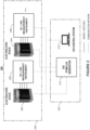
- FIG. 1 shows a conventional EIS monitoring system.
- Monitoring setup 100 includes cell electrolyzer stack 102, EIS stimulus 132 (typically an AC signal generator), and a measurement system comprising EIS engines (e.g., 134) coupled to one or more cells to allow for cell-by-cell measurements.
- EIS stimulus 132 typically an AC signal generator
- EIS engines e.g. 134
- AC signal generator 132 generates, in progressively varying increments, known sinusoidal voltage or current stimulus signals of distinct frequencies and relatively small amplitudes. These stimulus signals are then applied to each electrolyzer cell in stack 102.
- the measurement system examines the relationship between the stimulus signals and the resulting response signals across a specified frequency spectrum to calculate cell impedance.
- Response signals may be amplified and converted into an output voltage. Due to the impedance of the system, the response signals often exhibit a phase shift and amplitude changes relative to the stimulus signals.
- Demodulation techniques may be used to extract the amplitude and phase shift to enable separation of in-phase and out-of-phase components of the response signal to obtain complex impedance at the particular stimulus frequencies.
- the collected impedance data such as EIS spectra collected for each cell over time, may then be analyzed to gain insights into the electrochemical properties and, thus, the performance and operational conditions of individual cells within the electrolyzer stack 102. For example, by monitoring and analyzing impedance data, problems (inefficiencies, degradation, and faults in specific cells) may be detected, maintenance schedules for stacks may be optimized, and the overall efficiency and lifespan of electrolyzer stack 102 may be enhanced.
- the frequency of the sinusoidal excitation signal generated by the stimulus block is therefore confined within a relatively narrow frequency range around the frequency of interest during impedance measurements.
- the complex current supplied by the stimulus block may be measured simultaneously with the complex voltage across the cell or entity under test.
- a communications network comprising an isoSPI bus may be employed to connect the current and voltage measurements to the stimulus generator block.
- ICs measuring current and voltage may be triggered by a command that is transmitted over this communication network to perform measurements at designated frequencies.
- the stimulus block may transmit the generated frequency with a relatively high degree of precision to measurement chips to ensure that the ICs match and measure the same frequency accurately.
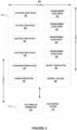
- FIG. 2 illustrates an electrolyzer system according to various embodiments of the present disclosure.
- system 200 comprises electrolyzer stacks 202, 204, measurement circuits 206, 208, EIS stimulus generator 210, and EIS control system 212. It is understood, that system 200 may comprise some or all of the elements shown in FIG. 1 . It is further understood that system 200 may further comprise amplifiers, power supplies, multiplexers, switches, and other auxiliary devices not expressly shown in FIG. 2 . Solid lines between elements indicate wiring and collection of switches, whereas dashed lines between elements indicate communication paths between elements. It is understood that any type of communication protocol, e.g., Ethernet or TCP IP may be employed.
- Ethernet or TCP IP may be employed.
- each measurement circuit 206, 208 is located near its corresponding electrolyzer stack 202, 204 for cell measurement purposes.
- EIS stimulus generator 210 in addition to EIS control system 202, may be situated remotely from electrolyzer stacks 202, 204 and measurement units 206, 208, e.g., at location 232, which may be subject to fewer safety requirements. This arrangement allows EIS stimulus generator 210 to serve any number of electrolyzer stacks 202, 204 by sequentially applying the generated stimulus signal to different stacks 202, 204, thereby significantly reducing development, equipment, and operational costs as would be recognized by those skilled in the art.
- EIS stimulus generator 210 For example, placing EIS stimulus generator 210 away from hydrogen production area 230 significantly simplifies thermal management.
- the EIS stimulus generator 210 can generate considerable heat (e.g., 10 kW), which can be dissipated much more effectively as cooling requirements would be less stringent to prevent unwanted contact with flammable gases, resulting in fewer design constraints and cost.
- EIS stimulus generator 210 does not require special insulation to prevent accidental exposure to hydrogen.
- EIS stimulus generator 210 may generate AC voltages or currents as input stimulus signals within a specified frequency range (e.g., 0.5 kHz - 25 kHz).
- a perturbation technique may be utilized which involves generating relatively small (e.g., 1%) stimulus signals that are superimposed or modulated onto DC signals that power electrolyzer stacks 202, 204.
- the stimulus signals may be directed to any number of electrolyzer stacks (e.g., 202, 204), e.g., via a switching circuit (not shown) that performs multiplexing or switching operations, where they can be detected using any known contact or noncontact type current measurement techniques like magnetoresistive sensors.
- each cell that receives a stimulus signal may generate an output voltage that can be detected by measurement circuits 206, 208.
- each measurement circuit 206, 208 may be configured to perform multiplexing or switching operations to connect the stimulus signals to different electrochemical cells or measurement points of electrolyzer stacks 202, 204, e.g., to apply the stimulus signals one at a time or to any combination of cells simultaneously.
- measurement circuits 206, 208 may be used to measure the DC signals and the stimulus signal at each electrolyzer stack 202, 204, e.g., in the form of a current, and any corresponding response signals, e.g., voltages at each electrolyzer cell in each stack 202, 204.
- the frequency range of measurement circuits 206, 208 may be limited.
- measurement circuit 206, 208 may generate its own reference signal at a frequency that mirrors the frequency of the stimulus signal, which may have been communicated to the measurement circuit 206, 208 on a data line, e.g., to perform demodulation operations.
- measurement circuits 206, 208 may select a measurement time of a frequency of interest, e.g., based on a desired settling or stabilization period.
- control system 212 may send and receive signals to facilitate impedance measurements, e.g., periodically or according to a measurement schedule. It is understood that, in embodiments, instead of utilizing cell-by-cell impedance measurements, groups of cells may be evaluated in combination. Similarly, the impedance of a stack as a whole may be evaluated.
- lowimpedance e.g., gold-plated
- the cell current and the cell voltage should be measured in a synchronized manner to minimize noise.
- the stimulus signal may be calibrated such as to provide a known waveform.
- a command serve as a trigger signal to synchronize that waveform and that measured at any given cell or combination of cells. It is understood that the calibrated the stimulus signal and/or any number of measured signals may further be processed to increase measurement accuracy.
- synchronization may be aided by the use of PLL circuits, clock circuits, and the like.
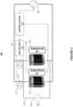
- FIG. 3 is an exemplary block diagram illustrating distances for a hydrogen generation plant layout according to various embodiments of the present disclosure. For clarity, components similar to those shown in FIG. 2 are labeled in the same manner. Items in the figures may not be to scale. Any distances and metrics in FIG. 3 represent one exemplary embodiment depicted therein and may differ between implementations depending on the application.
- hydrogen generation plant 300 comprises electrolyzer stacks 202-205, transformer / rectifier stations 312-318, hydrogen purification station 310, water purification station 320, power substation 130, central cooling system 340, stimulus generator 210, and EIS control system 212.
- electrolyzer stacks 202-205 transformer / rectifier stations 312-318
- hydrogen purification station 310 water purification station 320
- power substation 130 power substation 130
- central cooling system 340 for purposes of brevity, a description or their function is not repeated here. It is noted that any number of components may be modified, added, or deleted.
- hydrogen purification system 310 which may be used to purify fuel cells within electrolyzer stacks 202-205, may be optional.
- power substation 330 steps down a high mains voltage to medium voltage AC.
- Transformers and rectifiers 312-318 then convert the medium voltage AC into DC power that is provided to electrolyzer stacks 202-205, facilitating the electrolysis process to split water molecules into hydrogen and oxygen.
- Central cooling system 340 provides cooling water that circulates through electrolyzer stacks 202-205 to maintain electrolysis efficiency.
- stimulus generator 210 may be located at a distance away from electrolyzer stacks 202-205, e.g., in a separate room 232 as indicated by dashed lines. This arrangement of sharing stimulus generator 210 among electrolyzer stacks 202-205, advantageously, reduces size, weight, and cost at the system level and simplifies thermal design while complying with applicable ATEX requirements.
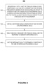
- FIG. 4 is a schematic of illustrative electrical interconnection for an exemplary system according to various embodiments of the present disclosure.
- circuit 400 comprises electrolyzer stacks (e.g., 202), EIS measurement units (e.g., 208), multiplexor 402, control system 404, stimulus signal generator 210, and/or actuators (e.g., 412), relays (e.g., 414), and DC current source 418.
Landscapes
- Health & Medical Sciences (AREA)
- Engineering & Computer Science (AREA)
- Chemical & Material Sciences (AREA)
- Life Sciences & Earth Sciences (AREA)
- Physics & Mathematics (AREA)
- Chemical Kinetics & Catalysis (AREA)
- Electrochemistry (AREA)
- General Health & Medical Sciences (AREA)
- Pathology (AREA)
- Materials Engineering (AREA)
- Metallurgy (AREA)
- Organic Chemistry (AREA)
- Signal Processing (AREA)
- Veterinary Medicine (AREA)
- Public Health (AREA)
- Animal Behavior & Ethology (AREA)
- Surgery (AREA)
- Molecular Biology (AREA)
- Medical Informatics (AREA)
- Heart & Thoracic Surgery (AREA)
- Biomedical Technology (AREA)
- Biophysics (AREA)
- Analytical Chemistry (AREA)
- General Physics & Mathematics (AREA)
- Automation & Control Theory (AREA)
- Artificial Intelligence (AREA)
- Psychiatry (AREA)
- Computer Vision & Pattern Recognition (AREA)
- Physiology (AREA)
- Spectroscopy & Molecular Physics (AREA)
- Immunology (AREA)
- Biochemistry (AREA)
- Nuclear Medicine, Radiotherapy & Molecular Imaging (AREA)
- Radiology & Medical Imaging (AREA)
- Electrolytic Production Of Non-Metals, Compounds, Apparatuses Therefor (AREA)
- Investigating Or Analyzing Materials By The Use Of Electric Means (AREA)
- Investigating, Analyzing Materials By Fluorescence Or Luminescence (AREA)
Applications Claiming Priority (1)
| Application Number | Priority Date | Filing Date | Title |
|---|---|---|---|
| US18/387,380 US20250146153A1 (en) | 2023-11-06 | 2023-11-06 | Shared electrolyzer monitoring systems and methods |
Publications (2)
| Publication Number | Publication Date |
|---|---|
| EP4549631A2 true EP4549631A2 (de) | 2025-05-07 |
| EP4549631A3 EP4549631A3 (de) | 2025-06-04 |
Family
ID=93379071
Family Applications (1)
| Application Number | Title | Priority Date | Filing Date |
|---|---|---|---|
| EP24210480.0A Pending EP4549631A3 (de) | 2023-11-06 | 2024-11-04 | Systeme und verfahren zur überwachung eines gemeinsamen elektrolyseurs |
Country Status (3)
| Country | Link |
|---|---|
| US (1) | US20250146153A1 (de) |
| EP (1) | EP4549631A3 (de) |
| CN (1) | CN119936708A (de) |
Family Cites Families (4)
| Publication number | Priority date | Publication date | Assignee | Title |
|---|---|---|---|---|
| CN103364472A (zh) * | 2013-07-12 | 2013-10-23 | 北京工业大学 | 一种基于电化学阻抗谱的防腐层剥离测试装置 |
| US10573910B2 (en) * | 2015-09-14 | 2020-02-25 | Bloom Energy Corporation | Electrochemical impedance spectroscopy (“EIS”) analyzer and method of using thereof |
| US20220112612A1 (en) * | 2020-10-13 | 2022-04-14 | Analog Devices, Inc. | Parallel configuration of electrolysis cells |
| EP4227438B1 (de) * | 2022-02-11 | 2024-12-25 | Abb Schweiz Ag | Verfahren zum betrieb einer vielzahl von elektrolyseurstapeln, und elektrolyseurstapeln-betriebssystem |
-
2023
- 2023-11-06 US US18/387,380 patent/US20250146153A1/en active Pending
-
2024
- 2024-08-02 CN CN202411052829.6A patent/CN119936708A/zh active Pending
- 2024-11-04 EP EP24210480.0A patent/EP4549631A3/de active Pending
Also Published As
| Publication number | Publication date |
|---|---|
| CN119936708A (zh) | 2025-05-06 |
| EP4549631A3 (de) | 2025-06-04 |
| US20250146153A1 (en) | 2025-05-08 |
Similar Documents
| Publication | Publication Date | Title |
|---|---|---|
| US9547044B2 (en) | Method and apparatus for the measurement of a resistance of a switching contact of an electrical circuit breaker | |
| CN105092999B (zh) | 利用多个指示的电力质量事件定位 | |
| Terzija et al. | Flexible synchronized measurement technology-based fault locator | |
| CN102472780A (zh) | 用于监控电网状态的方法和设备 | |
| US9423434B2 (en) | Method and system for measuring electrical quantity in electrical network | |
| Zhang et al. | Detecting measurement error drifts of a capacitor voltage transformer on-line and its field application | |
| EP3299826A1 (de) | Verfahren zur schätzung einer äquivalenten netzimpedanz für stromgeneratoren | |
| EP3770615B1 (de) | Bestimmung der elektrischen netzimpedanz | |
| EP4549631A2 (de) | Systeme und verfahren zur überwachung eines gemeinsamen elektrolyseurs | |
| CN105637730B (zh) | 电力系统及控制电力系统中的电力潮流和/或电压的方法 | |
| JP2012163384A (ja) | 短絡容量計測システム | |
| JP2003299215A (ja) | 開閉装置内の変流器の妥当性検査のための方法、コンピュータプログラム及び装置、ならびに該装置を有する開閉装置 | |
| Lin et al. | Dynamic performance test of single-phase phasor measurement units | |
| Mohamed et al. | Accurate fault location algorithm on power transmission lines with use of two-end unsynchronized measurements | |
| CN116325402A (zh) | 用于检测电力网络中的现象的方法及系统 | |
| Brijesh et al. | Synchrophasors evaluation and applications | |
| Costa et al. | Revision of target uncertainty for PMU-based distributed measurement systems in MV networks | |
| JP2005304227A (ja) | 分散電源の単独運転検出装置 | |
| EP4395122A1 (de) | Modulares diagnosesystem für das internet der dinge auf der grundlage der netzqualitätsanalyse | |
| Ngoc-Hung | A new method for estimating fault location in radial medium voltage distribution network only using measurements at feeder beginning | |
| Atri et al. | Nodal Monitoring in Medium Voltage Distribution Grid using Smart Sensored Cable Termination | |
| Valtari et al. | Method to increase sampling frequency by merging multiple measurements | |
| Kyriazis | Calibration of high-voltage current-comparator-based capacitance and dissipation factor bridges using nonsynchronous sampling | |
| Rabe et al. | Automated test procedures for accuracy verification of Phasor Measurement Units | |
| Dorraki et al. | Deconvolution-based correction of pre-strike arc voltage measurement in medium voltage switches |
Legal Events
| Date | Code | Title | Description |
|---|---|---|---|
| PUAI | Public reference made under article 153(3) epc to a published international application that has entered the european phase |
Free format text: ORIGINAL CODE: 0009012 |
|
| STAA | Information on the status of an ep patent application or granted ep patent |
Free format text: STATUS: REQUEST FOR EXAMINATION WAS MADE |
|
| 17P | Request for examination filed |
Effective date: 20241104 |
|
| AK | Designated contracting states |
Kind code of ref document: A2 Designated state(s): AL AT BE BG CH CY CZ DE DK EE ES FI FR GB GR HR HU IE IS IT LI LT LU LV MC ME MK MT NL NO PL PT RO RS SE SI SK SM TR |
|
| PUAL | Search report despatched |
Free format text: ORIGINAL CODE: 0009013 |
|
| AK | Designated contracting states |
Kind code of ref document: A3 Designated state(s): AL AT BE BG CH CY CZ DE DK EE ES FI FR GB GR HR HU IE IS IT LI LT LU LV MC ME MK MT NL NO PL PT RO RS SE SI SK SM TR |
|
| RIC1 | Information provided on ipc code assigned before grant |
Ipc: G01R 31/389 20190101ALI20250429BHEP Ipc: C25B 9/70 20210101ALI20250429BHEP Ipc: C25B 15/023 20210101AFI20250429BHEP |