EP4549266A1 - Emergency brake system for a heavy-duty vehicle - Google Patents
Emergency brake system for a heavy-duty vehicle Download PDFInfo
- Publication number
- EP4549266A1 EP4549266A1 EP23207445.0A EP23207445A EP4549266A1 EP 4549266 A1 EP4549266 A1 EP 4549266A1 EP 23207445 A EP23207445 A EP 23207445A EP 4549266 A1 EP4549266 A1 EP 4549266A1
- Authority
- EP
- European Patent Office
- Prior art keywords
- brake
- heavy
- auxiliary
- duty vehicle
- emergency
- Prior art date
- Legal status (The legal status is an assumption and is not a legal conclusion. Google has not performed a legal analysis and makes no representation as to the accuracy of the status listed.)
- Pending
Links
Images


Classifications
-
- B—PERFORMING OPERATIONS; TRANSPORTING
- B60—VEHICLES IN GENERAL
- B60T—VEHICLE BRAKE CONTROL SYSTEMS OR PARTS THEREOF; BRAKE CONTROL SYSTEMS OR PARTS THEREOF, IN GENERAL; ARRANGEMENT OF BRAKING ELEMENTS ON VEHICLES IN GENERAL; PORTABLE DEVICES FOR PREVENTING UNWANTED MOVEMENT OF VEHICLES; VEHICLE MODIFICATIONS TO FACILITATE COOLING OF BRAKES
- B60T8/00—Arrangements for adjusting wheel-braking force to meet varying vehicular or ground-surface conditions, e.g. limiting or varying distribution of braking force
- B60T8/32—Arrangements for adjusting wheel-braking force to meet varying vehicular or ground-surface conditions, e.g. limiting or varying distribution of braking force responsive to a speed condition, e.g. acceleration or deceleration
- B60T8/88—Arrangements for adjusting wheel-braking force to meet varying vehicular or ground-surface conditions, e.g. limiting or varying distribution of braking force responsive to a speed condition, e.g. acceleration or deceleration with failure responsive means, i.e. means for detecting and indicating faulty operation of the speed responsive control means
- B60T8/92—Arrangements for adjusting wheel-braking force to meet varying vehicular or ground-surface conditions, e.g. limiting or varying distribution of braking force responsive to a speed condition, e.g. acceleration or deceleration with failure responsive means, i.e. means for detecting and indicating faulty operation of the speed responsive control means automatically taking corrective action
- B60T8/94—Arrangements for adjusting wheel-braking force to meet varying vehicular or ground-surface conditions, e.g. limiting or varying distribution of braking force responsive to a speed condition, e.g. acceleration or deceleration with failure responsive means, i.e. means for detecting and indicating faulty operation of the speed responsive control means automatically taking corrective action on a fluid pressure regulator
-
- B—PERFORMING OPERATIONS; TRANSPORTING
- B60—VEHICLES IN GENERAL
- B60T—VEHICLE BRAKE CONTROL SYSTEMS OR PARTS THEREOF; BRAKE CONTROL SYSTEMS OR PARTS THEREOF, IN GENERAL; ARRANGEMENT OF BRAKING ELEMENTS ON VEHICLES IN GENERAL; PORTABLE DEVICES FOR PREVENTING UNWANTED MOVEMENT OF VEHICLES; VEHICLE MODIFICATIONS TO FACILITATE COOLING OF BRAKES
- B60T10/00—Control or regulation for continuous braking making use of fluid or powdered medium, e.g. for use when descending a long slope
-
- B—PERFORMING OPERATIONS; TRANSPORTING
- B60—VEHICLES IN GENERAL
- B60Q—ARRANGEMENT OF SIGNALLING OR LIGHTING DEVICES, THE MOUNTING OR SUPPORTING THEREOF OR CIRCUITS THEREFOR, FOR VEHICLES IN GENERAL
- B60Q1/00—Arrangement of optical signalling or lighting devices, the mounting or supporting thereof or circuits therefor
- B60Q1/26—Arrangement of optical signalling or lighting devices, the mounting or supporting thereof or circuits therefor the devices being primarily intended to indicate the vehicle, or parts thereof, or to give signals, to other traffic
- B60Q1/44—Arrangement of optical signalling or lighting devices, the mounting or supporting thereof or circuits therefor the devices being primarily intended to indicate the vehicle, or parts thereof, or to give signals, to other traffic for indicating braking action or preparation for braking, e.g. by detection of the foot approaching the brake pedal
-
- B—PERFORMING OPERATIONS; TRANSPORTING
- B60—VEHICLES IN GENERAL
- B60Q—ARRANGEMENT OF SIGNALLING OR LIGHTING DEVICES, THE MOUNTING OR SUPPORTING THEREOF OR CIRCUITS THEREFOR, FOR VEHICLES IN GENERAL
- B60Q1/00—Arrangement of optical signalling or lighting devices, the mounting or supporting thereof or circuits therefor
- B60Q1/26—Arrangement of optical signalling or lighting devices, the mounting or supporting thereof or circuits therefor the devices being primarily intended to indicate the vehicle, or parts thereof, or to give signals, to other traffic
- B60Q1/50—Arrangement of optical signalling or lighting devices, the mounting or supporting thereof or circuits therefor the devices being primarily intended to indicate the vehicle, or parts thereof, or to give signals, to other traffic for indicating other intentions or conditions, e.g. request for waiting or overtaking
- B60Q1/543—Arrangement of optical signalling or lighting devices, the mounting or supporting thereof or circuits therefor the devices being primarily intended to indicate the vehicle, or parts thereof, or to give signals, to other traffic for indicating other intentions or conditions, e.g. request for waiting or overtaking for indicating other states or conditions of the vehicle
-
- B—PERFORMING OPERATIONS; TRANSPORTING
- B60—VEHICLES IN GENERAL
- B60Q—ARRANGEMENT OF SIGNALLING OR LIGHTING DEVICES, THE MOUNTING OR SUPPORTING THEREOF OR CIRCUITS THEREFOR, FOR VEHICLES IN GENERAL
- B60Q9/00—Arrangement or adaptation of signal devices not provided for in one of main groups B60Q1/00 - B60Q7/00, e.g. haptic signalling
-
- B—PERFORMING OPERATIONS; TRANSPORTING
- B60—VEHICLES IN GENERAL
- B60T—VEHICLE BRAKE CONTROL SYSTEMS OR PARTS THEREOF; BRAKE CONTROL SYSTEMS OR PARTS THEREOF, IN GENERAL; ARRANGEMENT OF BRAKING ELEMENTS ON VEHICLES IN GENERAL; PORTABLE DEVICES FOR PREVENTING UNWANTED MOVEMENT OF VEHICLES; VEHICLE MODIFICATIONS TO FACILITATE COOLING OF BRAKES
- B60T13/00—Transmitting braking action from initiating means to ultimate brake actuator with power assistance or drive; Brake systems incorporating such transmitting means, e.g. air-pressure brake systems
- B60T13/10—Transmitting braking action from initiating means to ultimate brake actuator with power assistance or drive; Brake systems incorporating such transmitting means, e.g. air-pressure brake systems with fluid assistance, drive, or release
- B60T13/58—Combined or convertible systems
- B60T13/585—Combined or convertible systems comprising friction brakes and retarders
-
- B—PERFORMING OPERATIONS; TRANSPORTING
- B60—VEHICLES IN GENERAL
- B60T—VEHICLE BRAKE CONTROL SYSTEMS OR PARTS THEREOF; BRAKE CONTROL SYSTEMS OR PARTS THEREOF, IN GENERAL; ARRANGEMENT OF BRAKING ELEMENTS ON VEHICLES IN GENERAL; PORTABLE DEVICES FOR PREVENTING UNWANTED MOVEMENT OF VEHICLES; VEHICLE MODIFICATIONS TO FACILITATE COOLING OF BRAKES
- B60T13/00—Transmitting braking action from initiating means to ultimate brake actuator with power assistance or drive; Brake systems incorporating such transmitting means, e.g. air-pressure brake systems
- B60T13/10—Transmitting braking action from initiating means to ultimate brake actuator with power assistance or drive; Brake systems incorporating such transmitting means, e.g. air-pressure brake systems with fluid assistance, drive, or release
- B60T13/66—Electrical control in fluid-pressure brake systems
- B60T13/662—Electrical control in fluid-pressure brake systems characterised by specified functions of the control system components
-
- B—PERFORMING OPERATIONS; TRANSPORTING
- B60—VEHICLES IN GENERAL
- B60T—VEHICLE BRAKE CONTROL SYSTEMS OR PARTS THEREOF; BRAKE CONTROL SYSTEMS OR PARTS THEREOF, IN GENERAL; ARRANGEMENT OF BRAKING ELEMENTS ON VEHICLES IN GENERAL; PORTABLE DEVICES FOR PREVENTING UNWANTED MOVEMENT OF VEHICLES; VEHICLE MODIFICATIONS TO FACILITATE COOLING OF BRAKES
- B60T13/00—Transmitting braking action from initiating means to ultimate brake actuator with power assistance or drive; Brake systems incorporating such transmitting means, e.g. air-pressure brake systems
- B60T13/10—Transmitting braking action from initiating means to ultimate brake actuator with power assistance or drive; Brake systems incorporating such transmitting means, e.g. air-pressure brake systems with fluid assistance, drive, or release
- B60T13/66—Electrical control in fluid-pressure brake systems
- B60T13/68—Electrical control in fluid-pressure brake systems by electrically-controlled valves
- B60T13/683—Electrical control in fluid-pressure brake systems by electrically-controlled valves in pneumatic systems or parts thereof
-
- B—PERFORMING OPERATIONS; TRANSPORTING
- B60—VEHICLES IN GENERAL
- B60T—VEHICLE BRAKE CONTROL SYSTEMS OR PARTS THEREOF; BRAKE CONTROL SYSTEMS OR PARTS THEREOF, IN GENERAL; ARRANGEMENT OF BRAKING ELEMENTS ON VEHICLES IN GENERAL; PORTABLE DEVICES FOR PREVENTING UNWANTED MOVEMENT OF VEHICLES; VEHICLE MODIFICATIONS TO FACILITATE COOLING OF BRAKES
- B60T17/00—Component parts, details, or accessories of power brake systems not covered by groups B60T8/00, B60T13/00 or B60T15/00, or presenting other characteristic features
- B60T17/18—Safety devices; Monitoring
- B60T17/22—Devices for monitoring or checking brake systems; Signal devices
-
- B—PERFORMING OPERATIONS; TRANSPORTING
- B60—VEHICLES IN GENERAL
- B60T—VEHICLE BRAKE CONTROL SYSTEMS OR PARTS THEREOF; BRAKE CONTROL SYSTEMS OR PARTS THEREOF, IN GENERAL; ARRANGEMENT OF BRAKING ELEMENTS ON VEHICLES IN GENERAL; PORTABLE DEVICES FOR PREVENTING UNWANTED MOVEMENT OF VEHICLES; VEHICLE MODIFICATIONS TO FACILITATE COOLING OF BRAKES
- B60T8/00—Arrangements for adjusting wheel-braking force to meet varying vehicular or ground-surface conditions, e.g. limiting or varying distribution of braking force
- B60T8/17—Using electrical or electronic regulation means to control braking
-
- B—PERFORMING OPERATIONS; TRANSPORTING
- B60—VEHICLES IN GENERAL
- B60T—VEHICLE BRAKE CONTROL SYSTEMS OR PARTS THEREOF; BRAKE CONTROL SYSTEMS OR PARTS THEREOF, IN GENERAL; ARRANGEMENT OF BRAKING ELEMENTS ON VEHICLES IN GENERAL; PORTABLE DEVICES FOR PREVENTING UNWANTED MOVEMENT OF VEHICLES; VEHICLE MODIFICATIONS TO FACILITATE COOLING OF BRAKES
- B60T8/00—Arrangements for adjusting wheel-braking force to meet varying vehicular or ground-surface conditions, e.g. limiting or varying distribution of braking force
- B60T8/32—Arrangements for adjusting wheel-braking force to meet varying vehicular or ground-surface conditions, e.g. limiting or varying distribution of braking force responsive to a speed condition, e.g. acceleration or deceleration
- B60T8/321—Arrangements for adjusting wheel-braking force to meet varying vehicular or ground-surface conditions, e.g. limiting or varying distribution of braking force responsive to a speed condition, e.g. acceleration or deceleration deceleration
- B60T8/3255—Systems in which the braking action is dependent on brake pedal data
- B60T8/327—Pneumatic systems
-
- B—PERFORMING OPERATIONS; TRANSPORTING
- B60—VEHICLES IN GENERAL
- B60T—VEHICLE BRAKE CONTROL SYSTEMS OR PARTS THEREOF; BRAKE CONTROL SYSTEMS OR PARTS THEREOF, IN GENERAL; ARRANGEMENT OF BRAKING ELEMENTS ON VEHICLES IN GENERAL; PORTABLE DEVICES FOR PREVENTING UNWANTED MOVEMENT OF VEHICLES; VEHICLE MODIFICATIONS TO FACILITATE COOLING OF BRAKES
- B60T8/00—Arrangements for adjusting wheel-braking force to meet varying vehicular or ground-surface conditions, e.g. limiting or varying distribution of braking force
- B60T8/32—Arrangements for adjusting wheel-braking force to meet varying vehicular or ground-surface conditions, e.g. limiting or varying distribution of braking force responsive to a speed condition, e.g. acceleration or deceleration
- B60T8/88—Arrangements for adjusting wheel-braking force to meet varying vehicular or ground-surface conditions, e.g. limiting or varying distribution of braking force responsive to a speed condition, e.g. acceleration or deceleration with failure responsive means, i.e. means for detecting and indicating faulty operation of the speed responsive control means
- B60T8/885—Arrangements for adjusting wheel-braking force to meet varying vehicular or ground-surface conditions, e.g. limiting or varying distribution of braking force responsive to a speed condition, e.g. acceleration or deceleration with failure responsive means, i.e. means for detecting and indicating faulty operation of the speed responsive control means using electrical circuitry
-
- B—PERFORMING OPERATIONS; TRANSPORTING
- B60—VEHICLES IN GENERAL
- B60W—CONJOINT CONTROL OF VEHICLE SUB-UNITS OF DIFFERENT TYPE OR DIFFERENT FUNCTION; CONTROL SYSTEMS SPECIALLY ADAPTED FOR HYBRID VEHICLES; ROAD VEHICLE DRIVE CONTROL SYSTEMS FOR PURPOSES NOT RELATED TO THE CONTROL OF A PARTICULAR SUB-UNIT
- B60W10/00—Conjoint control of vehicle sub-units of different type or different function
- B60W10/10—Conjoint control of vehicle sub-units of different type or different function including control of change-speed gearings
- B60W10/11—Stepped gearings
-
- B—PERFORMING OPERATIONS; TRANSPORTING
- B60—VEHICLES IN GENERAL
- B60W—CONJOINT CONTROL OF VEHICLE SUB-UNITS OF DIFFERENT TYPE OR DIFFERENT FUNCTION; CONTROL SYSTEMS SPECIALLY ADAPTED FOR HYBRID VEHICLES; ROAD VEHICLE DRIVE CONTROL SYSTEMS FOR PURPOSES NOT RELATED TO THE CONTROL OF A PARTICULAR SUB-UNIT
- B60W10/00—Conjoint control of vehicle sub-units of different type or different function
- B60W10/18—Conjoint control of vehicle sub-units of different type or different function including control of braking systems
- B60W10/184—Conjoint control of vehicle sub-units of different type or different function including control of braking systems with wheel brakes
-
- B—PERFORMING OPERATIONS; TRANSPORTING
- B60—VEHICLES IN GENERAL
- B60W—CONJOINT CONTROL OF VEHICLE SUB-UNITS OF DIFFERENT TYPE OR DIFFERENT FUNCTION; CONTROL SYSTEMS SPECIALLY ADAPTED FOR HYBRID VEHICLES; ROAD VEHICLE DRIVE CONTROL SYSTEMS FOR PURPOSES NOT RELATED TO THE CONTROL OF A PARTICULAR SUB-UNIT
- B60W10/00—Conjoint control of vehicle sub-units of different type or different function
- B60W10/18—Conjoint control of vehicle sub-units of different type or different function including control of braking systems
- B60W10/196—Conjoint control of vehicle sub-units of different type or different function including control of braking systems acting within the driveline, e.g. retarders
-
- B—PERFORMING OPERATIONS; TRANSPORTING
- B60—VEHICLES IN GENERAL
- B60W—CONJOINT CONTROL OF VEHICLE SUB-UNITS OF DIFFERENT TYPE OR DIFFERENT FUNCTION; CONTROL SYSTEMS SPECIALLY ADAPTED FOR HYBRID VEHICLES; ROAD VEHICLE DRIVE CONTROL SYSTEMS FOR PURPOSES NOT RELATED TO THE CONTROL OF A PARTICULAR SUB-UNIT
- B60W30/00—Purposes of road vehicle drive control systems not related to the control of a particular sub-unit, e.g. of systems using conjoint control of vehicle sub-units
- B60W30/18—Propelling the vehicle
- B60W30/18009—Propelling the vehicle related to particular drive situations
- B60W30/18109—Braking
-
- B—PERFORMING OPERATIONS; TRANSPORTING
- B60—VEHICLES IN GENERAL
- B60T—VEHICLE BRAKE CONTROL SYSTEMS OR PARTS THEREOF; BRAKE CONTROL SYSTEMS OR PARTS THEREOF, IN GENERAL; ARRANGEMENT OF BRAKING ELEMENTS ON VEHICLES IN GENERAL; PORTABLE DEVICES FOR PREVENTING UNWANTED MOVEMENT OF VEHICLES; VEHICLE MODIFICATIONS TO FACILITATE COOLING OF BRAKES
- B60T2250/00—Monitoring, detecting, estimating vehicle conditions
- B60T2250/04—Vehicle reference speed; Vehicle body speed
-
- B—PERFORMING OPERATIONS; TRANSPORTING
- B60—VEHICLES IN GENERAL
- B60T—VEHICLE BRAKE CONTROL SYSTEMS OR PARTS THEREOF; BRAKE CONTROL SYSTEMS OR PARTS THEREOF, IN GENERAL; ARRANGEMENT OF BRAKING ELEMENTS ON VEHICLES IN GENERAL; PORTABLE DEVICES FOR PREVENTING UNWANTED MOVEMENT OF VEHICLES; VEHICLE MODIFICATIONS TO FACILITATE COOLING OF BRAKES
- B60T2270/00—Further aspects of brake control systems not otherwise provided for
- B60T2270/40—Failsafe aspects of brake control systems
- B60T2270/402—Back-up
-
- B—PERFORMING OPERATIONS; TRANSPORTING
- B60—VEHICLES IN GENERAL
- B60W—CONJOINT CONTROL OF VEHICLE SUB-UNITS OF DIFFERENT TYPE OR DIFFERENT FUNCTION; CONTROL SYSTEMS SPECIALLY ADAPTED FOR HYBRID VEHICLES; ROAD VEHICLE DRIVE CONTROL SYSTEMS FOR PURPOSES NOT RELATED TO THE CONTROL OF A PARTICULAR SUB-UNIT
- B60W50/00—Details of control systems for road vehicle drive control not related to the control of a particular sub-unit, e.g. process diagnostic or vehicle driver interfaces
- B60W50/08—Interaction between the driver and the control system
- B60W50/14—Means for informing the driver, warning the driver or prompting a driver intervention
- B60W2050/143—Alarm means
-
- B—PERFORMING OPERATIONS; TRANSPORTING
- B60—VEHICLES IN GENERAL
- B60W—CONJOINT CONTROL OF VEHICLE SUB-UNITS OF DIFFERENT TYPE OR DIFFERENT FUNCTION; CONTROL SYSTEMS SPECIALLY ADAPTED FOR HYBRID VEHICLES; ROAD VEHICLE DRIVE CONTROL SYSTEMS FOR PURPOSES NOT RELATED TO THE CONTROL OF A PARTICULAR SUB-UNIT
- B60W2510/00—Input parameters relating to a particular sub-units
- B60W2510/18—Braking system
- B60W2510/182—Brake pressure, e.g. of fluid or between pad and disc
-
- B—PERFORMING OPERATIONS; TRANSPORTING
- B60—VEHICLES IN GENERAL
- B60W—CONJOINT CONTROL OF VEHICLE SUB-UNITS OF DIFFERENT TYPE OR DIFFERENT FUNCTION; CONTROL SYSTEMS SPECIALLY ADAPTED FOR HYBRID VEHICLES; ROAD VEHICLE DRIVE CONTROL SYSTEMS FOR PURPOSES NOT RELATED TO THE CONTROL OF A PARTICULAR SUB-UNIT
- B60W2510/00—Input parameters relating to a particular sub-units
- B60W2510/18—Braking system
- B60W2510/186—Status of parking brakes
-
- B—PERFORMING OPERATIONS; TRANSPORTING
- B60—VEHICLES IN GENERAL
- B60W—CONJOINT CONTROL OF VEHICLE SUB-UNITS OF DIFFERENT TYPE OR DIFFERENT FUNCTION; CONTROL SYSTEMS SPECIALLY ADAPTED FOR HYBRID VEHICLES; ROAD VEHICLE DRIVE CONTROL SYSTEMS FOR PURPOSES NOT RELATED TO THE CONTROL OF A PARTICULAR SUB-UNIT
- B60W2520/00—Input parameters relating to overall vehicle dynamics
- B60W2520/10—Longitudinal speed
-
- B—PERFORMING OPERATIONS; TRANSPORTING
- B60—VEHICLES IN GENERAL
- B60W—CONJOINT CONTROL OF VEHICLE SUB-UNITS OF DIFFERENT TYPE OR DIFFERENT FUNCTION; CONTROL SYSTEMS SPECIALLY ADAPTED FOR HYBRID VEHICLES; ROAD VEHICLE DRIVE CONTROL SYSTEMS FOR PURPOSES NOT RELATED TO THE CONTROL OF A PARTICULAR SUB-UNIT
- B60W2710/00—Output or target parameters relating to a particular sub-units
- B60W2710/10—Change speed gearings
- B60W2710/1005—Transmission ratio engaged
-
- B—PERFORMING OPERATIONS; TRANSPORTING
- B60—VEHICLES IN GENERAL
- B60W—CONJOINT CONTROL OF VEHICLE SUB-UNITS OF DIFFERENT TYPE OR DIFFERENT FUNCTION; CONTROL SYSTEMS SPECIALLY ADAPTED FOR HYBRID VEHICLES; ROAD VEHICLE DRIVE CONTROL SYSTEMS FOR PURPOSES NOT RELATED TO THE CONTROL OF A PARTICULAR SUB-UNIT
- B60W2710/00—Output or target parameters relating to a particular sub-units
- B60W2710/18—Braking system
Definitions
- the disclosure relates generally to brake systems.
- the disclosure relates to an emergency brake system for a heavy-duty vehicle.
- the disclosure can be applied to heavy-duty vehicles, such as trucks, buses, and construction equipment, among other vehicle types.
- heavy-duty vehicles such as trucks, buses, and construction equipment, among other vehicle types.
- Heavy-duty vehicles are provided with brake circuits in which pressurized air is used for providing a braking action.
- Many heavy-duty vehicles have a primary and a secondary brake circuit. If brake circuit pressure fails so that satisfactory braking action is not available, the parking brake may still be used to help stopping the heavy-duty vehicle. However, the stopping distance is very long when using the parking brake. For emergency situations, it would therefore be desirable to shorten the stopping distance in case of brake circuit pressure failure.
- an emergency brake system for a heavy-duty vehicle comprising:
- the retarder brake may be located at the propeller shaft of the heavy-duty vehicle, in particular, the retarder brake may be located between a vehicle engine/motor and a differential in the propeller shaft.
- the retarder may suitably be activated by a driver, for example by controlling a retarder switch, when the driver desires retarder braking.
- the retarder brake may receive an electrical signal through the retarder switch. Activation of the retarder brake creates resistance in the propeller shaft rotation, thereby providing a braking force to the heavy-duty vehicle.
- the present disclosure is focused on automatic activation of the retarder brake in an emergency situation, without requiring the driver to manually activate the retarder brake.
- the retarder brake may, for example, be an electrical retarder brake or a hydraulic retarder brake.
- an electrical retarder brake may comprise a stator and a rotor. Electric windings in the stator may receive power from a battery, producing a magnetic field through which the rotor moves. In this case, the rotor is the propeller shaft. So, the rotation of the propeller shaft becomes restricted and the speed of the vehicle may be reduced.
- pressurized fluid may pass opposite to the direction of the propeller shaft rotation.
- the emergency brake system may further comprise:
- the auxiliary valve may comprise an exhaust port, wherein in the closed state of the auxiliary valve, pressurized air present in the part of the auxiliary brake circuit that extends between the auxiliary valve and said brake chambers is allowed to be evacuated through the exhaust port.
- a technical benefit may include that, after the emergency braking, before towing the heavy-duty vehicle away for repairing the faulty brake circuit, the auxiliary valve may conveniently be closed to evacuate the pressurized air in the auxiliary brake circuit, and thus releasing the service brakes so that the heavy-duty vehicle can be conveniently towed away.
- the auxiliary valve may act as an anti-compounding valve.
- said brake chambers may form part of front axle service brakes of the heavy-duty vehicle.
- a technical benefit may include that, oftentimes in known vehicles, during emergency braking the front axle brakes will not work.
- the stopping distance may become effectively shortened. Indeed, in many existing vehicles, during emergency braking by means of the parking brake, only rear axle brakes will work since they have spring brake chambers. However, by complementing such rear axle braking with the above exemplified front axle braking (by means of the pressure in the auxiliary brake circuit), the stopping distance may be reduced.
- the auxiliary valve may be a solenoid valve actuated into an open state by an electric signal from the processing circuitry.
- a technical benefit may include that a solenoid valve may be efficiently controlled by electronic signals, without requiring any additional mechanical control.
- the emergency brake system may further comprise:
- the emergency brake system may further comprise:
- the emergency brake system may further comprise:
- the processing circuitry may be configured to activate a brake taillight and/or hazard light of the heavy-duty vehicle in order to warn drivers in other vehicles.
- a technical benefit may include that the risk of a collision accident occurring may be reduced by warning other drivers about the emergency braking.
- said regular brake circuit is a first regular brake circuit
- said pressure sensor arrangement may be further configured to determine the pressure in a second regular brake circuit of the service brake system of the heavy-duty vehicle, wherein upon determination by the pressure sensor arrangement that the pressure in both the first and the second regular brake circuit is zero or below a predefined pressure threshold value, the pressure sensor arrangement issues said first signal, S 1.
- the emergency brake system may be readily implemented for a heavy-duty vehicle which has regular brake circuits in the form of a primary and a secondary brake circuit. As long as one of those two brake circuits is functioning properly, the processing circuitry does not need to trigger the emergency braking.
- the pressure sensor arrangement may suitably include a first pressure sensor for measuring the pressure in the primary brake circuit, and a second pressure sensor for measuring the pressure in the secondary brake circuit.
- said processing circuitry may comprise, in series connection, a first switch, a second switch and a third switch, each switch having an open state and a closed state, wherein the first, second and third switches are configured to become closed by the signals S1, S2, and S3, respectively,
- a heavy-duty vehicle comprises the emergency brake system of the first aspect, including any example thereof.
- the second aspect of the disclosure may seek to reduce the stopping distance of the heavy-duty vehicle in an emergency situation when the regular brake circuit to the service brakes does not work properly.
- a technical benefit may include that by enabling retarder braking in addition to parking braking, the stopping distance will be reduced compared to if only parking braking would be used.
- the heavy-duty vehicle may further comprise a manual retarder brake switch which is manually controllable by a driver to activate the retarder brake independently of the emergency brake system.
- a technical benefit may include during normal functioning, the driver may be free to activate the retarder brake at will, whereas in an emergency event, the emergency brake system will automatically activate the retarder brake to reduce the stopping distance.
- the stopping distance In case of failure of the ordinary service brake system of a heavy-duty vehicle, for example due to brake circuit failure, the stopping distance will be quite long, if only the parking brake is applied in such an emergency situation.
- the stopping distance may be reduced by automatically engaging a retarder brake of the vehicle during such an emergency situation. The application of the retarder brake will contribute in shortening the stopping distance.
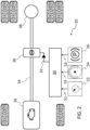
- FIG. 1 schematically illustrates a vehicle 1 according to one example of this disclosure. More specifically, the illustrated vehicle 1 is a heavy-duty vehicle combination which comprises a tractor unit 2 and a trailer unit 4.
- the tractor unit 2 has three wheel axles 6, 8, 10, each one of the wheel axles 6, 8, 10 having at least one left wheel and at least one right wheel.
- the tractor unit 2 has a front axle 6 and two rear axles 8, 10.
- One of the rear axles 8, 10 may be a lift axle. It should be understood that the teachings of this disclosure may also be implemented for vehicles without any lift axle.
- teachings of the present disclosure are not limited to a particular vehicle propulsion system, i.e., the teachings herein may be implemented for vehicles propelled by internal combustion engines, traction batteries, fuel cells, hybrid systems, etc. Furthermore, the teachings of the present disclosure may be implemented for driver-operated vehicles and for autonomous (self-driving) vehicles.
- the emergency brake system discussed in this disclosure may suitably be implemented in any one of the above-mentioned vehicles, including the illustrated vehicle 1. Some examples of the emergency brake system will be discussed in the following.
- FIG. 2 schematically illustrates an emergency brake system 20 for a heavy-duty vehicle, in accordance with one example of this disclosure.
- the illustrated emergency brake system 20 may be implemented in the vehicle 1 illustrated in FIG. 1 .
- the emergency brake system 20 comprises a pressure sensor arrangement 22 which is configured to determine the pressure in a regular brake circuit of a service brake system of the heavy-duty vehicle. Upon determination by the pressure sensor arrangement 22 that the pressure in the regular brake circuit is zero or below a pre-defined pressure threshold value, the pressure sensor arrangement 22 is configured to issue a first signal S1.
- the emergency brake system 20 further comprises a speed sensor 24 which is configured to determine the speed of the heavy-duty vehicle.
- the emergency brake system 20 further comprises a parking-brake sensor 26 which is configured to determine a state of a parking brake of the heavy-duty vehicle. Upon determination by the parking-brake sensor 26 that the parking brake is in an applied state, the parking-brake sensor 26 is configured to issue a third signal S3.
- the emergency brake system 20 further comprises a retarder brake 28 configured to decelerate the heavy-duty vehicle upon activation of the retarder brake 28.
- the emergency brake system 20 further comprises a processing circuitry 30 which is operatively connected to the pressure sensor arrangement 22, the speed sensor 24 and the parking-brake sensor 26.
- the processing circuitry 30 is configured to receive the signals S1, S2 and S3. Upon receiving all three signals S1, S2 and S3, the processing circuitry 30 is configured to activate the retarder brake. This is illustrated by an activation signal 32 from the processing circuitry 30 to the retarder brake 28.
- the processing circuitry 30 is configured to activate the retarder brake 28 in an emergency situation.
- the processing circuitry 30 interprets a current situation as an emergency situation when all three signals S 1, S2 and S3 are being received.
- the processing circuitry 30 will activate the retarder brake 28 in order to assist the parking-brake in bringing the heavy-duty vehicle to a stop.
- the retarder brake 28 will reduce the stopping distance compared to if only the parking-brake would be applied in such an emergency situation.
- the pressure sensor arrangement 22 may suitably have a measuring point between a pressurized air tank and a foot brake valve of the heavy-duty vehicle.
- the signal S 1 may be generated irrespectively of if the foot brake valve is activated or not.
- the predefined speed threshold may, in some examples, be a fixed value. However, in other examples, it may be predefined based on certain conditions or parameters. For instance, the current load carried by the vehicle may affect at which level to set the predefined speed threshold. When the heavy-duty vehicle is carrying a relatively heavy load, a lower predefined speed threshold may be selected compared to if the same vehicle drives empty. Thus, in at least some examples, the predefined speed threshold may be selected from a set of different values, or it may be calculated by using a speed function related to one or more other parameters of the heavy-duty vehicle.
- the retarder brake 28 may be located at the propeller shaft 34 of the heavy-duty vehicle, in particular, the retarder brake 28 may be located between a vehicle engine/motor 36 and a differential 38 in the propeller shaft 34. Activation of the retarder brake 28 creates resistance in the propeller shaft 34 rotation, thereby providing a braking force to the heavy-duty vehicle. By automatically including the braking action of the retarder brake 28 during an emergency event, the stopping distance can be reduced for the heavy-duty vehicle.
- FIG. 3 schematically illustrates an emergency brake system 40 for a heavy-duty vehicle, in accordance with another example of this disclosure.
- the emergency brake system 40 illustrated in FIG. 3 may include all the components previously discussed in relation to the example of FIG. 2 . Similar components are denoted with corresponding reference numerals.
- the pressure sensor arrangement 22a of this example of an emergency brake system 40 may suitably be configured to determine the pressure, not only in the primary brake circuit, but also in a secondary brake circuit of the service brake system of the heavy-duty vehicle. Upon determination by the pressure sensor arrangement 22a that the pressure in both the primary and the secondary brake circuit is zero or below a predefined threshold value, the pressure sensor arrangement 22a issues the first signal S 1.
- Both the primary brake circuit and the secondary brake circuit are regular brake circuits (as opposed to the auxiliary brake circuit discussed in this disclosure).
- regular brake circuits as opposed to the auxiliary brake circuit discussed in this disclosure.
- they may be in the form of a primary brake circuit and a secondary brake circuit, respectively; or in the form of a secondary brake circuit and a primary brake circuit, respectively.
- the emergency brake system 40 may further comprise a gear box 42 operatively connected to the propeller shaft 34.
- An existing gear box 42 of the vehicle may suitably be incorporated to form part of the emergency brake system 40.
- the processing circuitry 30 may, in addition to activating the retarder brake 28, suitably be configured to control the gear box 42 of the heavy-duty vehicle to downshift to a lower gear. This is illustrated by a gear shifting signal 44 transmitted from the processing circuitry 30 to the gear box 42. By such downshifting, the stopping distance may be reduced even more.
- Such an automatic downshifting may be suitable for heavy-duty vehicles comprising automatic transmission.
- the emergency brake system 40 may, as illustrated with dashed lines, comprise a driver alert interface 46.
- the processing circuitry 30 may be configured to send an alert message 48 or signal to the driver alert interface 46 so as to alert the driver to downshift to a lower gear.
- the processing circuitry 30 may be configured to activate a brake taillight and/or hazard light 50 of the heavy-duty vehicle in order to warn drivers in other vehicles. This is illustrated by an activation signal 52 sent from the processing circuitry 30 to the hazard light 50.
- FIG. 3 also illustrates that a heavy-duty vehicle may also comprise a manual retarder brake switch 54 which is manually controllable by a driver to activate the retarder brake 28 independently of the emergency brake system 40.
- the driver may when desired activate the retarder brake 28 by controlling the manual retarder brake switch 54, which is not part of the emergency brake system 40.
- the emergency brake system 40 will automatically activate the retarder brake 28 without the driver needing to control the manual retarder brake switch 54.
- the processing circuitry 30 may suitably include switches 56 which, when they are closed, activate/energize 58 the retarder brake 28, and suitably activate also at least some of the other components.
- switches 56 which, when they are closed, activate/energize 58 the retarder brake 28, and suitably activate also at least some of the other components.
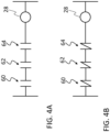
- An example of such a switch-based activation is illustrated in the ladder diagrams of FIGS. 4A-4B .
- FIGS. 4A-4B show ladder diagrams for illustrating an example of implementing the operation of a processing circuitry of the emergency brake system in accordance with one example (such as processing circuitry 30 of energy brake systems 20, 40 in FIGS. 2 and 3 ).
- the processing circuitry may comprise, in series connection, a first switch 60, a second switch 62 and a third switch 64.
- Each switch 60, 62, 64 has an open state and a closed state.
- FIG. 4A all three switches 60, 62, 64 are shown in their open states
- FIG. 4B all three switches 60, 62, 64 are shown in their closed states.
- the first switch 60 is configured to become closed by the first signal S1, i.e.
- the second switch 62 is configured to become closed by the second signal S2, i.e. from the speed sensor (e.g. speed sensor 24 in FIGS. 2 and 3 ).
- the third switch 64 is configured to become closed by the third signal S3, i.e. from the parking-brake sensor (e.g. the parking-brake sensor 24 in FIGS. 2 and 3 ).
- the processing circuitry is prevented from activating the retarder brake 28.
- each one of the first, second and third switches 60, 62, 64 is closed (as in FIG. 4B )
- an electrical signal is allowed to reach the retarder brake 28 so as to activate the retarder brake 28.
- the processing circuitry may include a microprocessor, microcontroller, programmable digital signal processor or another programmable device.
- the processing circuitry may also, or instead, include an application specific integrated circuit, a programmable gate array or programmable array logic, a programmable logic device, or a digital signal processor. Where it includes a programmable device such as the microprocessor, microcontroller or programmable digital signal processor mentioned above, the processor may further include computer executable code that controls operation of the programmable device.
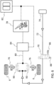
- FIGS. 5 and 6 illustrate that an auxiliary valve 70 provided in an auxiliary brake circuit 72 may be implemented in an emergency brake system, in accordance with an example of this disclosure.
- the auxiliary valve 70 may be comprised in the examples of the emergency brake system 20, 40 discussed in relation to FIGS. 2 and 3 , or in any other example of the emergency brake system of this disclosure.
- FIG. 5 illustrates the auxiliary valve 70 in a closed state.
- FIG. 6 illustrates the auxiliary valve 70 in an open state.
- the auxiliary brake circuit extends from an auxiliary pressure source 74, such as an auxiliary pressurized tank, compressor, etc., to brake chambers 76 of service brakes of the heavy-duty vehicle.
- the auxiliary valve 70 is provided in the auxiliary brake circuit 72 and has an open state ( FIG. 6 ) in which pressurized air is allowed to flow from the auxiliary pressure source 74 via the auxiliary brake circuit 72 to said brake chambers 76, and a closed state ( FIG. 5 ) in which pressurized air is prevented from flowing from the auxiliary pressure source 74 via the auxiliary brake circuit 72 to said brake chambers 76.
- the auxiliary valve 70 may suitably be controllable by the processing circuitry of the emergency brake system of this disclosure.
- the processing circuitry 30 discussed in relation to FIGS. 2 and 3 may suitably be configured to also control the state of the auxiliary valve 70.
- the processing circuitry upon receipt of all of said three signals S 1, S2 and S3, the processing circuitry (not shown in FIGS. 5 and 6 ) may be configured to open the auxiliary valve 70 to allow pressurized air from the auxiliary pressure source 74 to actuate the service brakes.
- FIG. 5 illustrates that under normal operating conditions, when a driver applies the foot brake valve 78 pressurized air may be supplied, via a regular brake circuit 80 (such as a primary or secondary brake circuit) to the brake chambers 76 from one or more pressurized air tanks 82 (suitably via an electronic brake system 84) so as to cause the service brakes to apply a braking force.
- a regular brake circuit 80 such as a primary or secondary brake circuit
- pressurized air tanks 82 suitable for example, the auxiliary valve 70 is in its closed state, and pressurized air cannot pass from the auxiliary pressure source 74 to the brake chambers 76 (as illustrated by the dashed line).
- auxiliary braking is provided which further reduces the stopping distance in an emergency situation.
- the processing circuitry will upon reception of signals S 1, S2 and S3, control the auxiliary valve 70 to move it into an open state, so as to allow the pressurized air to flow from the auxiliary pressure source 74 to the brake chambers 76 (as illustrated in FIG. 5 ).
- auxiliary braking is provided which further reduces the stopping distance in an emergency situation.
- only the front wheels 6 are illustrated, each front wheel 6 being provided with a respective brake chamber 76. It should, however, be understood that the corresponding implementation may also be provided for other wheels, such as rear wheels.
- the auxiliary valve 70 may comprise an exhaust port 86.
- pressurized air which is present in the part of the auxiliary brake circuit 72 that extends between the auxiliary valve 70 and the brake chambers 76 is allowed to be evacuated through the exhaust port 86.
- the auxiliary valve 70 may then be set to the closed state to in order to evacuate the pressurized air from the brake chambers 76 out through the exhaust port 86 (via the part of the auxiliary brake circuit 72 that extends between the brake chambers 76 and the auxiliary valve 70).
- the auxiliary valve 70 may also act as an anti-compounding valve.
- the auxiliary valve 70 may suitably be a solenoid valve which is actuated into the open state by an electric signal from the processing circuitry.
- the electric signal may for instance be generated or allowed to pass through switches 60, 62, 64 as illustrated in FIG. 4B .
- the processing circuitry may transmit the electric signal to the solenoid valve in different manner.
- any implementation in which the processing circuitry may cause the solenoid valve to become energized in an emergency situation (as manifested by the reception of signals S 1, S2 and S3), is conceivable for implementing the auxiliary braking.
- the solenoid valve (auxiliary valve 70) may suitably be provided with a spring 88 which biases the solenoid valve to a normally closed state ( FIG. 5 ). When the solenoid valve is energized, it is provided with a force that overcomes the biasing force of the spring 88 and moves the solenoid valve to the open state ( FIG. 6 ).
- the emergency brake system may further comprise a respective shuttle valve 90 associated with each brake chamber 76.
- Each shuttle valve 90 has three openings, a first opening to the brake chamber 76 of the service brake of the heavy-duty vehicle, a second opening to said auxiliary brake circuit 72, and a third opening to the regular brake circuit 80.
- the regular brake circuit supplies pressurized air to the shuttle valve ( FIG. 5 )
- the shuttle valve 90 closes fluid communication between the brake chamber 76 and the auxiliary brake circuit 72.
- the shuttle valve closes fluid communication between the brake chamber 76 and the regular brake circuit 80.
- Example 1 An emergency brake system for a heavy-duty vehicle, comprising:
- Example 2 The emergency brake system of example 1, further comprising:
- Example 3 The emergency brake system of example 2, wherein the auxiliary valve comprises an exhaust port, wherein in the closed state of the auxiliary valve, pressurized air present in the part of the auxiliary brake circuit that extends between the auxiliary valve and said brake chambers is allowed to be evacuated through the exhaust port.
- Example 4 The emergency brake system of any one of examples 2-3, wherein said brake chambers form part of front axle service brakes of the heavy-duty vehicle.
- Example 5 The emergency brake system of any one of examples 2-4, wherein the auxiliary valve is a solenoid valve actuated into an open state by an electric signal from the processing circuitry.
- Example 6 The emergency brake system of any one of examples 2-5, further comprising:
- Example 7 The emergency brake system of any of examples 1-6, further comprising:
- Example 8 The emergency brake system of any of examples 1-6, further comprising:
- Example 9 The emergency brake system of any one of examples 1-8, wherein upon receiving all of said three signals S1, S2 and S3, the processing circuitry is configured to activate a brake taillight and/or hazard light of the heavy-duty vehicle in order to warn drivers in other vehicles.
- Example 10 The emergency brake system of any one of examples 1-9, wherein the regular brake circuit is a first regular brake circuit, wherein said pressure sensor arrangement is further configured to determine the pressure in a second regular brake circuit of the service brake system of the heavy-duty vehicle, wherein upon determination by the pressure sensor arrangement that the pressure in both the first and the second regular brake circuit is zero or below a predefined pressure threshold value, the pressure sensor arrangement issues said first signal, S1.
- the regular brake circuit is a first regular brake circuit
- said pressure sensor arrangement is further configured to determine the pressure in a second regular brake circuit of the service brake system of the heavy-duty vehicle, wherein upon determination by the pressure sensor arrangement that the pressure in both the first and the second regular brake circuit is zero or below a predefined pressure threshold value, the pressure sensor arrangement issues said first signal, S1.
- Example 11 The emergency brake system of any one of examples 1-10,
- Example 12 A heavy-duty vehicle comprising the emergency brake system according to any of examples 1-11.
- Example 13 The heavy-duty vehicle of example 12, further comprising a manual retarder brake switch which is manually controllable by a driver to activate the retarder brake independently of the emergency brake system.
- Relative terms such as “below” or “above” or “upper” or “lower” or “horizontal” or “vertical” may be used herein to describe a relationship of one element to another element as illustrated in the Figures. It will be understood that these terms and those discussed above are intended to encompass different orientations of the device in addition to the orientation depicted in the Figures. It will be understood that when an element is referred to as being “connected” or “coupled” to another element, it can be directly connected or coupled to the other element, or intervening elements may be present. In contrast, when an element is referred to as being “directly connected” or “directly coupled” to another element, there are no intervening elements present.
Landscapes
- Engineering & Computer Science (AREA)
- Mechanical Engineering (AREA)
- Transportation (AREA)
- Chemical & Material Sciences (AREA)
- Combustion & Propulsion (AREA)
- Automation & Control Theory (AREA)
- Human Computer Interaction (AREA)
- Physics & Mathematics (AREA)
- Fluid Mechanics (AREA)
- Braking Systems And Boosters (AREA)
Abstract
An emergency brake system (20, 40) for a heavy-duty vehicle, comprising a pressure sensor arrangement (22, 22a) configured to issue a first signal, S1, upon determination that the pressure in a regular brake circuit is zero or below a predefined pressure threshold value, a speed sensor (24) configured to issue a second signal, S2, upon determination that the speed of the heavy-duty vehicle exceeds a predefined speed threshold, a parking-brake sensor (26) configured to issue a third signal, S3, upon determination that the parking brake is in an applied state, a retarder brake (28) configured to decelerate the heavy-duty vehicle upon activation of the retarder brake, and a processing circuitry (30) configured to activate the retarder brake upon receiving all of said three signals S1, S2 and S3.
Description
- The disclosure relates generally to brake systems. In particular aspects, the disclosure relates to an emergency brake system for a heavy-duty vehicle. The disclosure can be applied to heavy-duty vehicles, such as trucks, buses, and construction equipment, among other vehicle types. Although the disclosure may be described with respect to a particular vehicle, the disclosure is not restricted to any particular vehicle.
- Heavy-duty vehicles are provided with brake circuits in which pressurized air is used for providing a braking action. Many heavy-duty vehicles have a primary and a secondary brake circuit. If brake circuit pressure fails so that satisfactory braking action is not available, the parking brake may still be used to help stopping the heavy-duty vehicle. However, the stopping distance is very long when using the parking brake. For emergency situations, it would therefore be desirable to shorten the stopping distance in case of brake circuit pressure failure.
- According to a first aspect of the disclosure, there is provided an emergency brake system for a heavy-duty vehicle. The emergency brake system comprises:
- a pressure sensor arrangement configured to determine the pressure in a regular brake circuit of a service brake system of the heavy-duty vehicle, wherein upon determination by the pressure sensor arrangement that the pressure in the regular brake circuit is zero or below a predefined pressure threshold value, the pressure sensor arrangement is configured to issue a first signal,
S 1, - a speed sensor configured to determine the speed of the heavy-duty vehicle, wherein upon determination by the speed sensor that the speed of the heavy-duty vehicle exceeds a predefined speed threshold, the speed sensor is configured to issue a second signal, S2,
- a parking-brake sensor configured to determine a state of a parking brake of the heavy-duty vehicle, wherein upon determination by the parking-brake sensor that the parking brake is in an applied state, the parking-brake sensor is configured to issue a third signal, S3,
- a retarder brake configured to decelerate the heavy-duty vehicle upon activation of the retarder brake,
- a processing circuitry operatively connected to said pressure sensor arrangement, said speed sensor and said parking-brake sensor,
- The retarder brake may be located at the propeller shaft of the heavy-duty vehicle, in particular, the retarder brake may be located between a vehicle engine/motor and a differential in the propeller shaft. Under normal driving conditions, the retarder may suitably be activated by a driver, for example by controlling a retarder switch, when the driver desires retarder braking. When the driver manually activates the retarder brake switch, the retarder brake may receive an electrical signal through the retarder switch. Activation of the retarder brake creates resistance in the propeller shaft rotation, thereby providing a braking force to the heavy-duty vehicle. The present disclosure, however, is focused on automatic activation of the retarder brake in an emergency situation, without requiring the driver to manually activate the retarder brake. By automatically adding the retarder brake during an emergency event, the stopping distance can be reduced for the heavy-duty vehicle. The retarder brake may, for example, be an electrical retarder brake or a hydraulic retarder brake. For instance, an electrical retarder brake may comprise a stator and a rotor. Electric windings in the stator may receive power from a battery, producing a magnetic field through which the rotor moves. In this case, the rotor is the propeller shaft. So, the rotation of the propeller shaft becomes restricted and the speed of the vehicle may be reduced. In a hydraulic retarder, pressurized fluid may pass opposite to the direction of the propeller shaft rotation.
- Optionally in some examples, including in at least one preferred example, the emergency brake system may further comprise:
- an auxiliary valve provided in an auxiliary brake circuit extending from an auxiliary pressure source to brake chambers of service brakes of the heavy-duty vehicle, wherein the auxiliary valve has an open state in which pressurized air is allowed to flow from the auxiliary pressure source via the auxiliary brake circuit to said brake chambers, and a closed state in which pressurized air is prevented from flowing from the auxiliary pressure source via the auxiliary brake circuit to said brake chambers,
- Optionally in some examples, including in at least one preferred example, the auxiliary valve may comprise an exhaust port, wherein in the closed state of the auxiliary valve, pressurized air present in the part of the auxiliary brake circuit that extends between the auxiliary valve and said brake chambers is allowed to be evacuated through the exhaust port. A technical benefit may include that, after the emergency braking, before towing the heavy-duty vehicle away for repairing the faulty brake circuit, the auxiliary valve may conveniently be closed to evacuate the pressurized air in the auxiliary brake circuit, and thus releasing the service brakes so that the heavy-duty vehicle can be conveniently towed away. Furthermore, hereby the auxiliary valve may act as an anti-compounding valve.
- Optionally in some examples, including in at least one preferred example, said brake chambers may form part of front axle service brakes of the heavy-duty vehicle. A technical benefit may include that, oftentimes in known vehicles, during emergency braking the front axle brakes will not work. By applying auxiliary braking to the front axle, the stopping distance may become effectively shortened. Indeed, in many existing vehicles, during emergency braking by means of the parking brake, only rear axle brakes will work since they have spring brake chambers. However, by complementing such rear axle braking with the above exemplified front axle braking (by means of the pressure in the auxiliary brake circuit), the stopping distance may be reduced.
- Optionally in some examples, including in at least one preferred example, the auxiliary valve may be a solenoid valve actuated into an open state by an electric signal from the processing circuitry. A technical benefit may include that a solenoid valve may be efficiently controlled by electronic signals, without requiring any additional mechanical control.
- Optionally in some examples, including in at least one preferred example, the emergency brake system may further comprise:
- a shuttle valve having three openings, a first opening to a brake chamber of the service brake of the heavy-duty vehicle, a second opening to said auxiliary brake circuit, and a third opening to the regular brake circuit,
- Optionally in some examples, including in at least one preferred example, the emergency brake system may further comprise:
- a gear box,
- Optionally in some examples, including in at least one preferred example, the emergency brake system may further comprise:
- a driver alert interface,
- Optionally in some examples, including in at least one preferred example, upon receiving all of said three signals S1, S2 and S3, the processing circuitry may be configured to activate a brake taillight and/or hazard light of the heavy-duty vehicle in order to warn drivers in other vehicles. A technical benefit may include that the risk of a collision accident occurring may be reduced by warning other drivers about the emergency braking.
- Optionally in some examples, including in at least one preferred example, said regular brake circuit is a first regular brake circuit, wherein said pressure sensor arrangement may be further configured to determine the pressure in a second regular brake circuit of the service brake system of the heavy-duty vehicle, wherein upon determination by the pressure sensor arrangement that the pressure in both the first and the second regular brake circuit is zero or below a predefined pressure threshold value, the pressure sensor arrangement issues said first signal,
S 1. A technical benefit may include that the emergency brake system may be readily implemented for a heavy-duty vehicle which has regular brake circuits in the form of a primary and a secondary brake circuit. As long as one of those two brake circuits is functioning properly, the processing circuitry does not need to trigger the emergency braking. The pressure sensor arrangement may suitably include a first pressure sensor for measuring the pressure in the primary brake circuit, and a second pressure sensor for measuring the pressure in the secondary brake circuit. - Optionally in some examples, including in at least one preferred example, said the processing circuitry may comprise, in series connection, a first switch, a second switch and a third switch, each switch having an open state and a closed state, wherein the first, second and third switches are configured to become closed by the signals S1, S2, and S3, respectively,
- wherein when at least one of the first, second and third switches is open, the processing circuitry is prevented from activating the retarder brake,
- wherein when each one of the first, second and third switches is closed, an electrical signal is sent to the retarder brake so as to activate the retarder brake.
- According to a second aspect of the disclosure, there is provided a heavy-duty vehicle. The heavy-duty vehicle comprises the emergency brake system of the first aspect, including any example thereof. The second aspect of the disclosure may seek to reduce the stopping distance of the heavy-duty vehicle in an emergency situation when the regular brake circuit to the service brakes does not work properly. A technical benefit may include that by enabling retarder braking in addition to parking braking, the stopping distance will be reduced compared to if only parking braking would be used.
- Optionally in some examples, including in at least one preferred example, the heavy-duty vehicle may further comprise a manual retarder brake switch which is manually controllable by a driver to activate the retarder brake independently of the emergency brake system. A technical benefit may include during normal functioning, the driver may be free to activate the retarder brake at will, whereas in an emergency event, the emergency brake system will automatically activate the retarder brake to reduce the stopping distance.
- The disclosed aspects, examples (including any preferred examples), and/or accompanying claims may be suitably combined with each other as would be apparent to anyone of ordinary skill in the art. Additional features and advantages are disclosed in the following description, claims, and drawings, and in part will be readily apparent therefrom to those skilled in the art or recognized by practicing the disclosure as described herein.
- Examples are described in more detail below with reference to the appended drawings.
-
FIG. 1 schematically illustrates a vehicle according to one example of this disclosure. -
FIG. 2 schematically illustrates an emergency brake system for a heavy-duty vehicle, in accordance with one example of this disclosure. -
FIG. 3 schematically illustrates an emergency brake system for a heavy-duty vehicle, in accordance with another example of this disclosure. -
FIGS. 4A-4B show ladder diagrams for illustrating an example of implementing the operation of a processing circuitry of the emergency brake system in accordance with one example. -
FIGS. 5 and6 illustrate that an auxiliary valve provided in an auxiliary brake circuit may be implemented in an emergency brake system, in accordance with an example of this disclosure. - The detailed description set forth below provides information and examples of the disclosed technology with sufficient detail to enable those skilled in the art to practice the disclosure.
- In case of failure of the ordinary service brake system of a heavy-duty vehicle, for example due to brake circuit failure, the stopping distance will be quite long, if only the parking brake is applied in such an emergency situation. According to the teachings of the present disclosure, the stopping distance may be reduced by automatically engaging a retarder brake of the vehicle during such an emergency situation. The application of the retarder brake will contribute in shortening the stopping distance.
-
FIG. 1 schematically illustrates avehicle 1 according to one example of this disclosure. More specifically, the illustratedvehicle 1 is a heavy-duty vehicle combination which comprises a tractor unit 2 and atrailer unit 4. The tractor unit 2 has threewheel axles wheel axles front axle 6 and tworear axles rear axles vehicle 1. Some examples of the emergency brake system will be discussed in the following. -
FIG. 2 schematically illustrates anemergency brake system 20 for a heavy-duty vehicle, in accordance with one example of this disclosure. For instance, the illustratedemergency brake system 20 may be implemented in thevehicle 1 illustrated inFIG. 1 . Theemergency brake system 20 comprises apressure sensor arrangement 22 which is configured to determine the pressure in a regular brake circuit of a service brake system of the heavy-duty vehicle. Upon determination by thepressure sensor arrangement 22 that the pressure in the regular brake circuit is zero or below a pre-defined pressure threshold value, thepressure sensor arrangement 22 is configured to issue a first signal S1. Theemergency brake system 20 further comprises aspeed sensor 24 which is configured to determine the speed of the heavy-duty vehicle. Upon determination by thespeed sensor 24 that the speed of the heavy-duty vehicle exceeds a predefined speed threshold, thespeed sensor 24 is configured to issue a second signal S2. Theemergency brake system 20 further comprises a parking-brake sensor 26 which is configured to determine a state of a parking brake of the heavy-duty vehicle. Upon determination by the parking-brake sensor 26 that the parking brake is in an applied state, the parking-brake sensor 26 is configured to issue a third signal S3. Theemergency brake system 20 further comprises aretarder brake 28 configured to decelerate the heavy-duty vehicle upon activation of theretarder brake 28. Theemergency brake system 20 further comprises aprocessing circuitry 30 which is operatively connected to thepressure sensor arrangement 22, thespeed sensor 24 and the parking-brake sensor 26. Theprocessing circuitry 30 is configured to receive the signals S1, S2 and S3. Upon receiving all three signals S1, S2 and S3, theprocessing circuitry 30 is configured to activate the retarder brake. This is illustrated by anactivation signal 32 from theprocessing circuitry 30 to theretarder brake 28. - Thus, the
processing circuitry 30 is configured to activate theretarder brake 28 in an emergency situation. Theprocessing circuitry 30 interprets a current situation as an emergency situation when all threesignals S 1, S2 and S3 are being received. Thus, in an emergency situation, when the service brakes do not function properly, for example due to the lack of sufficient pressure in the regular brake circuit, and the heavy-duty vehicle is travelling at a relatively high speed, and the parking-brake is being applied, then theprocessing circuitry 30 will activate theretarder brake 28 in order to assist the parking-brake in bringing the heavy-duty vehicle to a stop. Theretarder brake 28 will reduce the stopping distance compared to if only the parking-brake would be applied in such an emergency situation. - The
pressure sensor arrangement 22 may suitably have a measuring point between a pressurized air tank and a foot brake valve of the heavy-duty vehicle. Thus, thesignal S 1 may be generated irrespectively of if the foot brake valve is activated or not. - The predefined speed threshold may, in some examples, be a fixed value. However, in other examples, it may be predefined based on certain conditions or parameters. For instance, the current load carried by the vehicle may affect at which level to set the predefined speed threshold. When the heavy-duty vehicle is carrying a relatively heavy load, a lower predefined speed threshold may be selected compared to if the same vehicle drives empty. Thus, in at least some examples, the predefined speed threshold may be selected from a set of different values, or it may be calculated by using a speed function related to one or more other parameters of the heavy-duty vehicle.
- As illustrated in
FIG. 2 , theretarder brake 28 may be located at thepropeller shaft 34 of the heavy-duty vehicle, in particular, theretarder brake 28 may be located between a vehicle engine/motor 36 and a differential 38 in thepropeller shaft 34. Activation of theretarder brake 28 creates resistance in thepropeller shaft 34 rotation, thereby providing a braking force to the heavy-duty vehicle. By automatically including the braking action of theretarder brake 28 during an emergency event, the stopping distance can be reduced for the heavy-duty vehicle. -
FIG. 3 schematically illustrates anemergency brake system 40 for a heavy-duty vehicle, in accordance with another example of this disclosure. Theemergency brake system 40 illustrated inFIG. 3 may include all the components previously discussed in relation to the example ofFIG. 2 . Similar components are denoted with corresponding reference numerals. - Many heavy-duty vehicles are provided with a primary brake circuit and a secondary brake circuit. One of the brake circuits may be configured to cause braking of rear wheels, while the other one of the brake circuits may be configured to cause braking of the front wheels. As illustrated schematically in
FIG. 3 , thepressure sensor arrangement 22a of this example of anemergency brake system 40 may suitably be configured to determine the pressure, not only in the primary brake circuit, but also in a secondary brake circuit of the service brake system of the heavy-duty vehicle. Upon determination by thepressure sensor arrangement 22a that the pressure in both the primary and the secondary brake circuit is zero or below a predefined threshold value, thepressure sensor arrangement 22a issues thefirst signal S 1. Both the primary brake circuit and the secondary brake circuit are regular brake circuits (as opposed to the auxiliary brake circuit discussed in this disclosure). Thus, it should be understood that in this disclosure when discussing a first regular brake circuit and a second regular brake circuit, they may be in the form of a primary brake circuit and a secondary brake circuit, respectively; or in the form of a secondary brake circuit and a primary brake circuit, respectively. - Additionally, as illustrated in
FIG. 3 , theemergency brake system 40 may further comprise agear box 42 operatively connected to thepropeller shaft 34. An existinggear box 42 of the vehicle may suitably be incorporated to form part of theemergency brake system 40. Upon receiving all three signals S1, S2 and S3 theprocessing circuitry 30 may, in addition to activating theretarder brake 28, suitably be configured to control thegear box 42 of the heavy-duty vehicle to downshift to a lower gear. This is illustrated by agear shifting signal 44 transmitted from theprocessing circuitry 30 to thegear box 42. By such downshifting, the stopping distance may be reduced even more. Such an automatic downshifting may be suitable for heavy-duty vehicles comprising automatic transmission. In other examples, in particular for heavy-duty vehicles comprising manual transmission, theemergency brake system 40 may, as illustrated with dashed lines, comprise adriver alert interface 46. Upon receiving all of said three signals S1, S2 and S3, theprocessing circuitry 30 may be configured to send an alert message 48 or signal to thedriver alert interface 46 so as to alert the driver to downshift to a lower gear. - In some examples, upon receiving all of said three
signals S 1, S2 and S3, theprocessing circuitry 30 may be configured to activate a brake taillight and/orhazard light 50 of the heavy-duty vehicle in order to warn drivers in other vehicles. This is illustrated by anactivation signal 52 sent from theprocessing circuitry 30 to thehazard light 50. -
FIG. 3 also illustrates that a heavy-duty vehicle may also comprise a manualretarder brake switch 54 which is manually controllable by a driver to activate theretarder brake 28 independently of theemergency brake system 40. Thus, under normal operating conditions, the driver may when desired activate theretarder brake 28 by controlling the manualretarder brake switch 54, which is not part of theemergency brake system 40. However, in an emergency situation, when the driver is applying the parking brake, theemergency brake system 40 will automatically activate theretarder brake 28 without the driver needing to control the manualretarder brake switch 54. - As symbolically indicated in
FIG. 3 , theprocessing circuitry 30 may suitably includeswitches 56 which, when they are closed, activate/energize 58 theretarder brake 28, and suitably activate also at least some of the other components. An example of such a switch-based activation is illustrated in the ladder diagrams ofFIGS. 4A-4B . -
FIGS. 4A-4B show ladder diagrams for illustrating an example of implementing the operation of a processing circuitry of the emergency brake system in accordance with one example (such asprocessing circuitry 30 ofenergy brake systems FIGS. 2 and3 ). As illustrated inFIGS. 4A-4B , the processing circuitry may comprise, in series connection, afirst switch 60, asecond switch 62 and athird switch 64. Eachswitch FIG. 4A all threeswitches FIG. 4B all threeswitches first switch 60 is configured to become closed by the first signal S1, i.e. the signal from the pressure sensor arrangement (e.g.pressure sensor arrangement FIGS. 2 and3 ). Thesecond switch 62 is configured to become closed by the second signal S2, i.e. from the speed sensor (e.g. speed sensor 24 inFIGS. 2 and3 ). Thethird switch 64 is configured to become closed by the third signal S3, i.e. from the parking-brake sensor (e.g. the parking-brake sensor 24 inFIGS. 2 and3 ). When at least one of the first, second andthird switches retarder brake 28, and theretarder brake 28 will therefore not become energized. Thus, when at least one of the first, second andthird switches retarder brake 28. However, when each one of the first, second andthird switches FIG. 4B ), an electrical signal is allowed to reach theretarder brake 28 so as to activate theretarder brake 28. - In other examples the processing circuitry may include a microprocessor, microcontroller, programmable digital signal processor or another programmable device. The processing circuitry may also, or instead, include an application specific integrated circuit, a programmable gate array or programmable array logic, a programmable logic device, or a digital signal processor. Where it includes a programmable device such as the microprocessor, microcontroller or programmable digital signal processor mentioned above, the processor may further include computer executable code that controls operation of the programmable device.
-
FIGS. 5 and6 illustrate that anauxiliary valve 70 provided in anauxiliary brake circuit 72 may be implemented in an emergency brake system, in accordance with an example of this disclosure. For instance, theauxiliary valve 70 may be comprised in the examples of theemergency brake system FIGS. 2 and3 , or in any other example of the emergency brake system of this disclosure. -
FIG. 5 illustrates theauxiliary valve 70 in a closed state.FIG. 6 illustrates theauxiliary valve 70 in an open state. The auxiliary brake circuit extends from anauxiliary pressure source 74, such as an auxiliary pressurized tank, compressor, etc., to brakechambers 76 of service brakes of the heavy-duty vehicle. Theauxiliary valve 70 is provided in theauxiliary brake circuit 72 and has an open state (FIG. 6 ) in which pressurized air is allowed to flow from theauxiliary pressure source 74 via theauxiliary brake circuit 72 to saidbrake chambers 76, and a closed state (FIG. 5 ) in which pressurized air is prevented from flowing from theauxiliary pressure source 74 via theauxiliary brake circuit 72 to saidbrake chambers 76. Theauxiliary valve 70 may suitably be controllable by the processing circuitry of the emergency brake system of this disclosure. For instance, theprocessing circuitry 30 discussed in relation toFIGS. 2 and3 (or in relation to any other example of this disclosure) may suitably be configured to also control the state of theauxiliary valve 70. Thus, upon receipt of all of said threesignals S 1, S2 and S3, the processing circuitry (not shown inFIGS. 5 and6 ) may be configured to open theauxiliary valve 70 to allow pressurized air from theauxiliary pressure source 74 to actuate the service brakes. -
FIG. 5 illustrates that under normal operating conditions, when a driver applies thefoot brake valve 78 pressurized air may be supplied, via a regular brake circuit 80 (such as a primary or secondary brake circuit) to thebrake chambers 76 from one or more pressurized air tanks 82 (suitably via an electronic brake system 84) so as to cause the service brakes to apply a braking force. Under such normal operating conditions, theauxiliary valve 70 is in its closed state, and pressurized air cannot pass from theauxiliary pressure source 74 to the brake chambers 76 (as illustrated by the dashed line). However, in an emergency condition when the regular (primary and/or secondary)brake circuit 80 does not function properly, such that the pressure is too low, then the processing circuitry will upon reception ofsignals S 1, S2 and S3, control theauxiliary valve 70 to move it into an open state, so as to allow the pressurized air to flow from theauxiliary pressure source 74 to the brake chambers 76 (as illustrated inFIG. 5 ). Hereby, auxiliary braking is provided which further reduces the stopping distance in an emergency situation. In this example, only thefront wheels 6 are illustrated, eachfront wheel 6 being provided with arespective brake chamber 76. It should, however, be understood that the corresponding implementation may also be provided for other wheels, such as rear wheels. - With reference to
FIG. 5 , theauxiliary valve 70 may comprise anexhaust port 86. In the closed state of theauxiliary valve 70, pressurized air which is present in the part of theauxiliary brake circuit 72 that extends between theauxiliary valve 70 and thebrake chambers 76 is allowed to be evacuated through theexhaust port 86. After an emergency stop, in which theauxiliary valve 70 was opened to provide the auxiliary braking, theauxiliary valve 70 may then be set to the closed state to in order to evacuate the pressurized air from thebrake chambers 76 out through the exhaust port 86 (via the part of theauxiliary brake circuit 72 that extends between thebrake chambers 76 and the auxiliary valve 70). Hereby, towing away of the vehicle is facilitated. Theauxiliary valve 70 may also act as an anti-compounding valve. - The
auxiliary valve 70 may suitably be a solenoid valve which is actuated into the open state by an electric signal from the processing circuitry. The electric signal may for instance be generated or allowed to pass through switches 60, 62, 64 as illustrated inFIG. 4B . However, in other examples, the processing circuitry may transmit the electric signal to the solenoid valve in different manner. Thus, any implementation in which the processing circuitry may cause the solenoid valve to become energized in an emergency situation (as manifested by the reception ofsignals S 1, S2 and S3), is conceivable for implementing the auxiliary braking. The solenoid valve (auxiliary valve 70) may suitably be provided with aspring 88 which biases the solenoid valve to a normally closed state (FIG. 5 ). When the solenoid valve is energized, it is provided with a force that overcomes the biasing force of thespring 88 and moves the solenoid valve to the open state (FIG. 6 ). - As illustrated in
FIGS. 5 and6 , the emergency brake system may further comprise arespective shuttle valve 90 associated with eachbrake chamber 76. Eachshuttle valve 90 has three openings, a first opening to thebrake chamber 76 of the service brake of the heavy-duty vehicle, a second opening to saidauxiliary brake circuit 72, and a third opening to theregular brake circuit 80. When the regular brake circuit supplies pressurized air to the shuttle valve (FIG. 5 ), theshuttle valve 90 closes fluid communication between thebrake chamber 76 and theauxiliary brake circuit 72. In contrast, when theauxiliary brake circuit 72 supplies pressurized air to the shuttle valve 90 (FIG. 6 ), the shuttle valve closes fluid communication between thebrake chamber 76 and theregular brake circuit 80. - Example 1: An emergency brake system for a heavy-duty vehicle, comprising:
- a pressure sensor arrangement configured to determine the pressure in a regular brake circuit of a service brake system of the heavy-duty vehicle, wherein upon determination by the pressure sensor arrangement that the pressure in the regular brake circuit is zero or below a predefined pressure threshold value, the pressure sensor arrangement is configured to issue a first signal, S1,
- a speed sensor configured to determine the speed of the heavy-duty vehicle, wherein upon determination by the speed sensor that the speed of the heavy-duty vehicle exceeds a predefined speed threshold, the speed sensor is configured to issue a second signal, S2,
- a parking-brake sensor configured to determine a state of a parking brake of the heavy-duty vehicle, wherein upon determination by the parking-brake sensor that the parking brake is in an applied state, the parking-brake sensor is configured to issue a third signal, S3,
- a retarder brake configured to decelerate the heavy-duty vehicle upon activation of the retarder brake,
- a processing circuitry operatively connected to said pressure sensor arrangement, said speed sensor and said parking-brake sensor,
- Example 2: The emergency brake system of example 1, further comprising:
- an auxiliary valve provided in an auxiliary brake circuit extending from an auxiliary pressure source to brake chambers of service brakes of the heavy-duty vehicle, wherein the auxiliary valve has an open state in which pressurized air is allowed to flow from the auxiliary pressure source via the auxiliary brake circuit to said brake chambers, and a closed state in which pressurized air is prevented from flowing from the auxiliary pressure source via the auxiliary brake circuit to said brake chambers,
- Example 3: The emergency brake system of example 2, wherein the auxiliary valve comprises an exhaust port, wherein in the closed state of the auxiliary valve, pressurized air present in the part of the auxiliary brake circuit that extends between the auxiliary valve and said brake chambers is allowed to be evacuated through the exhaust port.
- Example 4: The emergency brake system of any one of examples 2-3, wherein said brake chambers form part of front axle service brakes of the heavy-duty vehicle.
- Example 5: The emergency brake system of any one of examples 2-4, wherein the auxiliary valve is a solenoid valve actuated into an open state by an electric signal from the processing circuitry.
- Example 6: The emergency brake system of any one of examples 2-5, further comprising:
- a shuttle valve having three openings, a first opening to a brake chamber of the service brake of the heavy-duty vehicle, a second opening to said auxiliary brake circuit, and a third opening to the regular brake circuit,
- Example 7: The emergency brake system of any of examples 1-6, further comprising:
- a gear box,
- Example 8: The emergency brake system of any of examples 1-6, further comprising:
- a driver alert interface,
- Example 9: The emergency brake system of any one of examples 1-8, wherein upon receiving all of said three signals S1, S2 and S3, the processing circuitry is configured to activate a brake taillight and/or hazard light of the heavy-duty vehicle in order to warn drivers in other vehicles.
- Example 10: The emergency brake system of any one of examples 1-9, wherein the regular brake circuit is a first regular brake circuit, wherein said pressure sensor arrangement is further configured to determine the pressure in a second regular brake circuit of the service brake system of the heavy-duty vehicle, wherein upon determination by the pressure sensor arrangement that the pressure in both the first and the second regular brake circuit is zero or below a predefined pressure threshold value, the pressure sensor arrangement issues said first signal, S1.
- Example 11: The emergency brake system of any one of examples 1-10,
- wherein the processing circuitry comprises, in series connection, a first switch, a second switch and a third switch, each switch having an open state and a closed state,
- wherein the first, second and third switches are configured to become closed by the signals S1, S2, and S3, respectively,
- wherein when at least one of the first, second and third switches is open, the processing circuitry is prevented from activating the retarder brake,
- wherein when each one of the first, second and third switches is closed, an electrical signal is sent to the retarder brake so as to activate the retarder brake.
- Example 12: A heavy-duty vehicle comprising the emergency brake system according to any of examples 1-11.
- Example 13: The heavy-duty vehicle of example 12, further comprising a manual retarder brake switch which is manually controllable by a driver to activate the retarder brake independently of the emergency brake system.
- The terminology used herein is for the purpose of describing particular aspects only and is not intended to be limiting of the disclosure. As used herein, the singular forms "a," "an," and "the" are intended to include the plural forms as well, unless the context clearly indicates otherwise. As used herein, the term "and/or" includes any and all combinations of one or more of the associated listed items. It will be further understood that the terms "comprises," "comprising," "includes," and/or "including" when used herein specify the presence of stated features, integers, actions, steps, operations, elements, and/or components, but do not preclude the presence or addition of one or more other features, integers, actions, steps, operations, elements, components, and/or groups thereof.
- It will be understood that, although the terms first, second, etc., may be used herein to describe various elements, these elements should not be limited by these terms. These terms are only used to distinguish one element from another. For example, a first element could be termed a second element, and, similarly, a second element could be termed a first element without departing from the scope of the present disclosure.
- Relative terms such as "below" or "above" or "upper" or "lower" or "horizontal" or "vertical" may be used herein to describe a relationship of one element to another element as illustrated in the Figures. It will be understood that these terms and those discussed above are intended to encompass different orientations of the device in addition to the orientation depicted in the Figures. It will be understood that when an element is referred to as being "connected" or "coupled" to another element, it can be directly connected or coupled to the other element, or intervening elements may be present. In contrast, when an element is referred to as being "directly connected" or "directly coupled" to another element, there are no intervening elements present.
- Unless otherwise defined, all terms (including technical and scientific terms) used herein have the same meaning as commonly understood by one of ordinary skill in the art to which this disclosure belongs. It will be further understood that terms used herein should be interpreted as having a meaning consistent with their meaning in the context of this specification and the relevant art and will not be interpreted in an idealized or overly formal sense unless expressly so defined herein.
- It is to be understood that the present disclosure is not limited to the aspects described above and illustrated in the drawings; rather, the skilled person will recognize that many changes and modifications may be made within the scope of the present disclosure and appended claims. In the drawings and specification, there have been disclosed aspects for purposes of illustration only and not for purposes of limitation, the scope of the disclosure being set forth in the following claims.
The first aspect of the disclosure may seek to reduce the stopping distance of a heavy-duty vehicle in an emergency situation when the regular brake circuit to the service brakes does not work properly. A technical benefit may include that by enabling retarder braking in addition to parking braking, the stopping distance will be reduced compared to if only parking braking would be used. The processing circuitry may thus get information through the
Claims (13)
- An emergency brake system for a heavy-duty vehicle, comprising:- a pressure sensor arrangement configured to determine the pressure in a regular brake circuit of a service brake system of the heavy-duty vehicle, wherein upon determination by the pressure sensor arrangement that the pressure in the regular brake circuit is zero or below a predefined pressure threshold value, the pressure sensor arrangement is configured to issue a first signal, S1,- a speed sensor configured to determine the speed of the heavy-duty vehicle, wherein upon determination by the speed sensor that the speed of the heavy-duty vehicle exceeds a predefined speed threshold, the speed sensor is configured to issue a second signal, S2,- a parking-brake sensor configured to determine a state of a parking brake of the heavy-duty vehicle, wherein upon determination by the parking-brake sensor that the parking brake is in an applied state, the parking-brake sensor is configured to issue a third signal, S3,- a retarder brake configured to decelerate the heavy-duty vehicle upon activation of the retarder brake,- a processing circuitry operatively connected to said pressure sensor arrangement, said speed sensor and said parking-brake sensor,wherein, upon receiving all of said three signals S1, S2 and S3, the processing circuitry is configured to activate the retarder brake.
- The emergency brake system of claim 1, further comprising:- an auxiliary valve provided in an auxiliary brake circuit extending from an auxiliary pressure source to brake chambers of service brakes of the heavy-duty vehicle, wherein the auxiliary valve has an open state in which pressurized air is allowed to flow from the auxiliary pressure source via the auxiliary brake circuit to said brake chambers, and a closed state in which pressurized air is prevented from flowing from the auxiliary pressure source via the auxiliary brake circuit to said brake chambers,wherein, upon receiving all of said three signals S1, S2 and S3, the processing circuitry is configured to open the auxiliary valve to allow pressurized air from the auxiliary pressure source to actuate said service brakes.
- The emergency brake system of claim 2, wherein the auxiliary valve comprises an exhaust port, wherein in the closed state of the auxiliary valve, pressurized air present in the part of the auxiliary brake circuit that extends between the auxiliary valve and said brake chambers is allowed to be evacuated through the exhaust port.
- The emergency brake system of any one of claims 2-3, wherein said brake chambers form part of front axle service brakes of the heavy-duty vehicle.
- The emergency brake system of any one of claims 2-4, wherein the auxiliary valve is a solenoid valve actuated into an open state by an electric signal from the processing circuitry.
- The emergency brake system of any one of claims 2-5, further comprising:- a shuttle valve having three openings, a first opening to a brake chamber of the service brake of the heavy-duty vehicle, a second opening to said auxiliary brake circuit, and a third opening to the regular brake circuit,wherein when the regular brake circuit supplies pressurized air to the shuttle valve, the shuttle valve closes fluid communication between the brake chamber and the auxiliary brake circuit.
- The emergency brake system of any of claims 1-6, further comprising:- a gear box,wherein upon receiving all of said three signals S1, S2 and S3, the processing circuitry is configured to control the gear box of the heavy-duty vehicle to downshift to a lower gear.
- The emergency brake system of any of claims 1-6, further comprising:- a driver alert interface,wherein upon receiving all of said three signals S1, S2 and S3, the processing circuitry is configured to send an alert message or signal to the driver alert interface so as to alert the driver to downshift to a lower gear.
- The emergency brake system of any one of claims 1-8, wherein upon receiving all of said three signals S1, S2 and S3, the processing circuitry is configured to activate a brake taillight and/or hazard light of the heavy-duty vehicle in order to warn drivers in other vehicles.
- The emergency brake system of any one of claims 1-9, wherein said regular brake circuit is a first regular brake circuit, wherein said pressure sensor arrangement is further configured to determine the pressure in a second regular brake circuit of the service brake system of the heavy-duty vehicle, wherein upon determination by the pressure sensor arrangement that the pressure in both the first and the second regular brake circuit is zero or below a predefined pressure threshold value, the pressure sensor arrangement issues said first signal, S1.
- The emergency brake system of any one of claims 1-10,wherein the processing circuitry comprises, in series connection, a first switch, a second switch and a third switch, each switch having an open state and a closed state,wherein the first, second and third switches are configured to become closed by the signals S1, S2, and S3, respectively,wherein when at least one of the first, second and third switches is open, the processing circuitry is prevented from activating the retarder brake,wherein when each one of the first, second and third switches is closed, an electrical signal is sent to the retarder brake so as to activate the retarder brake.
- A heavy-duty vehicle comprising the emergency brake system according to any of claims 1-11.
- The heavy-duty vehicle of claim 12, further comprising a manual retarder brake switch which is manually controllable by a driver to activate the retarder brake independently of the emergency brake system.
Priority Applications (2)
| Application Number | Priority Date | Filing Date | Title |
|---|---|---|---|
| EP23207445.0A EP4549266A1 (en) | 2023-11-02 | 2023-11-02 | Emergency brake system for a heavy-duty vehicle |
| US18/921,092 US20250145131A1 (en) | 2023-11-02 | 2024-10-21 | Emergency brake system for a heavy-duty vehicle |
Applications Claiming Priority (1)
| Application Number | Priority Date | Filing Date | Title |
|---|---|---|---|
| EP23207445.0A EP4549266A1 (en) | 2023-11-02 | 2023-11-02 | Emergency brake system for a heavy-duty vehicle |
Publications (1)
| Publication Number | Publication Date |
|---|---|
| EP4549266A1 true EP4549266A1 (en) | 2025-05-07 |
Family
ID=88689370
Family Applications (1)
| Application Number | Title | Priority Date | Filing Date |
|---|---|---|---|
| EP23207445.0A Pending EP4549266A1 (en) | 2023-11-02 | 2023-11-02 | Emergency brake system for a heavy-duty vehicle |
Country Status (2)
| Country | Link |
|---|---|
| US (1) | US20250145131A1 (en) |
| EP (1) | EP4549266A1 (en) |
Families Citing this family (1)
| Publication number | Priority date | Publication date | Assignee | Title |
|---|---|---|---|---|
| US20250360897A1 (en) * | 2024-05-23 | 2025-11-27 | Bendix Commercial Vehicle Systems Llc | Emergency brake control apparatus for a vehicle train |
Citations (6)
| Publication number | Priority date | Publication date | Assignee | Title |
|---|---|---|---|---|
| WO1988006990A1 (en) * | 1987-03-10 | 1988-09-22 | Zahnradfabrik Friedrichshafen Ag | Braking system for full-track vehicles |
| DE3734489A1 (en) * | 1987-08-26 | 1989-04-20 | Herbert Haedrich | Emergency brake arrangement for truck or similar vehicle |
| DE102005016001A1 (en) * | 2005-04-07 | 2006-10-12 | Robert Bosch Gmbh | Braking a vehicle as part of an emergency stop |
| DE102013212364A1 (en) * | 2013-06-27 | 2014-12-31 | Zf Friedrichshafen Ag | Method and apparatus for generating an emergency braking signal for a vehicle and method for initiating an emergency braking operation of a vehicle |
| KR20190069778A (en) * | 2017-12-12 | 2019-06-20 | 현대자동차주식회사 | Method for using auxiliary brake in emergency braking |
| CN113958630A (en) * | 2021-09-08 | 2022-01-21 | 中国北方车辆研究所 | Mechanical hydraulic composite retarding brake device |
Family Cites Families (6)
| Publication number | Priority date | Publication date | Assignee | Title |
|---|---|---|---|---|
| US5139315A (en) * | 1991-02-28 | 1992-08-18 | General Motors Corporation | Vehicle parking brake system and method |
| US6697521B2 (en) * | 2001-06-15 | 2004-02-24 | Nokia Mobile Phones Ltd. | Method and system for achieving coding gains in wavelet-based image codecs |
| US7509197B2 (en) * | 2005-01-31 | 2009-03-24 | Caterpillar Inc. | Retarding system implementing transmission control |
| US7670259B2 (en) * | 2007-01-05 | 2010-03-02 | Gm Global Technology Operations, Inc. | Automatic braking system |
| KR102030842B1 (en) * | 2017-09-29 | 2019-10-10 | 주식회사 만도 | Brake Control Apparatus and Control Method Thereof |
| KR102935122B1 (en) * | 2021-03-11 | 2026-03-06 | 현대자동차주식회사 | Braking control system for vehicle and method for controlling braking of vehicle |
-
2023
- 2023-11-02 EP EP23207445.0A patent/EP4549266A1/en active Pending
-
2024
- 2024-10-21 US US18/921,092 patent/US20250145131A1/en active Pending
Patent Citations (6)
| Publication number | Priority date | Publication date | Assignee | Title |
|---|---|---|---|---|
| WO1988006990A1 (en) * | 1987-03-10 | 1988-09-22 | Zahnradfabrik Friedrichshafen Ag | Braking system for full-track vehicles |
| DE3734489A1 (en) * | 1987-08-26 | 1989-04-20 | Herbert Haedrich | Emergency brake arrangement for truck or similar vehicle |
| DE102005016001A1 (en) * | 2005-04-07 | 2006-10-12 | Robert Bosch Gmbh | Braking a vehicle as part of an emergency stop |
| DE102013212364A1 (en) * | 2013-06-27 | 2014-12-31 | Zf Friedrichshafen Ag | Method and apparatus for generating an emergency braking signal for a vehicle and method for initiating an emergency braking operation of a vehicle |
| KR20190069778A (en) * | 2017-12-12 | 2019-06-20 | 현대자동차주식회사 | Method for using auxiliary brake in emergency braking |
| CN113958630A (en) * | 2021-09-08 | 2022-01-21 | 中国北方车辆研究所 | Mechanical hydraulic composite retarding brake device |
Also Published As
| Publication number | Publication date |
|---|---|
| US20250145131A1 (en) | 2025-05-08 |
Similar Documents
| Publication | Publication Date | Title |
|---|---|---|
| US11292440B2 (en) | Automatic parking control method and automatic parking control apparatus for vehicles | |
| US6516925B1 (en) | System and method for braking a towed conveyance | |
| US6866350B2 (en) | Regenerative braking on an electrical vehicle when towed | |
| US8141667B2 (en) | Hybrid dinghy pusher | |
| EP2159119A1 (en) | Steering systems and methods for hybrid vehicles | |
| CN114641405B (en) | Method and device for braking a commercial vehicle by means of an electric drive | |
| CN207089288U (en) | A kind of electronic parking system based on air pressure redundancy | |
| CN111086515A (en) | Method for operating a backup brake system of a motor vehicle | |
| US20250145131A1 (en) | Emergency brake system for a heavy-duty vehicle | |
| CN107512260A (en) | A kind of electronic parking system based on air pressure redundancy | |
| CN116061958A (en) | A control system for wheel-end-by-wire chassis | |
| JP2016511718A (en) | Electronically controlled air brake system for a vehicle, a vehicle comprising such a system and a method for controlling such a system | |
| CN117465217A (en) | Towed motorized vehicle control | |
| JP2020192975A (en) | Interlock system for self-driving cars | |
| US20110203400A1 (en) | Device and method for operating a drive having an electrically drivable axle | |
| CN109649163B (en) | Vehicle traveling system, control method thereof and sanitation vehicle | |
| CN111605614A (en) | Enabling control method and device for electro-hydraulic power steering system | |
| JP2005343248A (en) | Parking assist brake controlling device | |
| CN214420428U (en) | Temporary parking device | |
| CN112937538B (en) | Electronic parking brake control method | |
| JP4613520B2 (en) | Parking assistance control device, parking assistance control system, and parking assistance program | |
| CN108290557A (en) | vehicle with electric parking brake | |
| JPH01111550A (en) | Control device for turning on brake lamp of vehicle | |
| CN111252076B (en) | A kind of troubleshooting method, device and hybrid vehicle | |
| CN120645698B (en) | Vehicle low-voltage power consumption control system based on regional control architecture and vehicle |
Legal Events
| Date | Code | Title | Description |
|---|---|---|---|
| PUAI | Public reference made under article 153(3) epc to a published international application that has entered the european phase |
Free format text: ORIGINAL CODE: 0009012 |
|
| STAA | Information on the status of an ep patent application or granted ep patent |
Free format text: STATUS: THE APPLICATION HAS BEEN PUBLISHED |
|
| AK | Designated contracting states |
Kind code of ref document: A1 Designated state(s): AL AT BE BG CH CY CZ DE DK EE ES FI FR GB GR HR HU IE IS IT LI LT LU LV MC ME MK MT NL NO PL PT RO RS SE SI SK SM TR |
|
| STAA | Information on the status of an ep patent application or granted ep patent |
Free format text: STATUS: REQUEST FOR EXAMINATION WAS MADE |
|
| 17P | Request for examination filed |
Effective date: 20250616 |