EP4549051A1 - Tundish for continuous casting, steel continuous casting method, and gas supply device - Google Patents
Tundish for continuous casting, steel continuous casting method, and gas supply device Download PDFInfo
- Publication number
- EP4549051A1 EP4549051A1 EP23862834.1A EP23862834A EP4549051A1 EP 4549051 A1 EP4549051 A1 EP 4549051A1 EP 23862834 A EP23862834 A EP 23862834A EP 4549051 A1 EP4549051 A1 EP 4549051A1
- Authority
- EP
- European Patent Office
- Prior art keywords
- inert gas
- gas supply
- continuous casting
- flow rate
- supply unit
- Prior art date
- Legal status (The legal status is an assumption and is not a legal conclusion. Google has not performed a legal analysis and makes no representation as to the accuracy of the status listed.)
- Pending
Links
Images

Classifications
-
- B—PERFORMING OPERATIONS; TRANSPORTING
- B22—CASTING; POWDER METALLURGY
- B22D—CASTING OF METALS; CASTING OF OTHER SUBSTANCES BY THE SAME PROCESSES OR DEVICES
- B22D41/00—Casting melt-holding vessels, e.g. ladles, tundishes, cups or the like
-
- B—PERFORMING OPERATIONS; TRANSPORTING
- B22—CASTING; POWDER METALLURGY
- B22D—CASTING OF METALS; CASTING OF OTHER SUBSTANCES BY THE SAME PROCESSES OR DEVICES
- B22D11/00—Continuous casting of metals, i.e. casting in indefinite lengths
- B22D11/10—Supplying or treating molten metal
- B22D11/11—Treating the molten metal
- B22D11/116—Refining the metal
- B22D11/117—Refining the metal by treating with gases
-
- B—PERFORMING OPERATIONS; TRANSPORTING
- B22—CASTING; POWDER METALLURGY
- B22D—CASTING OF METALS; CASTING OF OTHER SUBSTANCES BY THE SAME PROCESSES OR DEVICES
- B22D1/00—Treatment of fused masses in the ladle or the supply runners before casting
- B22D1/002—Treatment with gases
-
- B—PERFORMING OPERATIONS; TRANSPORTING
- B22—CASTING; POWDER METALLURGY
- B22D—CASTING OF METALS; CASTING OF OTHER SUBSTANCES BY THE SAME PROCESSES OR DEVICES
- B22D1/00—Treatment of fused masses in the ladle or the supply runners before casting
- B22D1/002—Treatment with gases
- B22D1/005—Injection assemblies therefor
-
- B—PERFORMING OPERATIONS; TRANSPORTING
- B22—CASTING; POWDER METALLURGY
- B22D—CASTING OF METALS; CASTING OF OTHER SUBSTANCES BY THE SAME PROCESSES OR DEVICES
- B22D11/00—Continuous casting of metals, i.e. casting in indefinite lengths
- B22D11/10—Supplying or treating molten metal
-
- B—PERFORMING OPERATIONS; TRANSPORTING
- B22—CASTING; POWDER METALLURGY
- B22D—CASTING OF METALS; CASTING OF OTHER SUBSTANCES BY THE SAME PROCESSES OR DEVICES
- B22D11/00—Continuous casting of metals, i.e. casting in indefinite lengths
- B22D11/10—Supplying or treating molten metal
- B22D11/11—Treating the molten metal
-
- B—PERFORMING OPERATIONS; TRANSPORTING
- B22—CASTING; POWDER METALLURGY
- B22D—CASTING OF METALS; CASTING OF OTHER SUBSTANCES BY THE SAME PROCESSES OR DEVICES
- B22D41/00—Casting melt-holding vessels, e.g. ladles, tundishes, cups or the like
- B22D41/12—Travelling ladles or similar containers; Cars for ladles
Definitions
- the present invention relates to a continuous casting tundish, a method for continuously casting steel, and a gas supply device.
- a process for manufacturing steel materials is as follows. Molten steel is supplied from a ladle to a tundish. The molten steel is then supplied to a casting mold and cast to form a cast steel. The cast steel is subjected to processes including rolling and thus formed into a predetermined shape to serve as a steel material.
- Inclusions in molten steel can cause a defect in the steel material, and, therefore, it is preferable to separate and remove inclusions from molten steel prior to casting.
- an approach being used in tundishes is to separate inclusions present in molten steel by causing the inclusions to float.
- an approach being used is to provide a tundish with a weir that separates a steel receiving region, to which molten steel is supplied, from a steel quasi-static region, from which the molten steel is discharged through an outlet provided in a bottom portion.
- a weir described in Patent Literature 1 has holes formed in a region adjacent to a bottom portion of a tundish, the holes extending from an area of a steel receiving region-side to an area of a steel quasi-static region-side.
- the weir limits the movement of inclusions that have a lower specific gravity than molten steel.
- the molten steel flows from the steel receiving region-side to the steel quasi-static region-side by passing through the holes of the weir.
- Patent Literature 2 discloses that a weir described in Patent Literature 1 is provided in a tundish and also discloses that a rib extending upward from a bottom portion of the tundish is provided on the steel quasi-static region-side. Accordingly, even when inclusions move to the steel quasi-static region-side through the holes of the weir, the direction of their movement can be changed to an upper direction by the rib. Accordingly, the inclusions can be floated even on the steel receiving region-side.
- Patent Literature 3 discloses that a weir described in Patent Literature 1 is provided in a tundish and also discloses that an inert gas is supplied to the steel quasi-static region-side from a bottom portion of the tundish toward an upper end. Accordingly, even when inclusions move to the steel quasi-static region-side through the holes of the weir, the inclusions are floated by the inert gas.
- Patent Literature 2 Regarding the floating of inclusions by using a rib as disclosed in Patent Literature 2, a need exists to more effectively float inclusions, and, therefore, there is still room for improvement. Furthermore, a problem arises in that the molten steel between the rib and the weir remains when the casting is completed, which results in an increase in cost associated with the disposal of the remaining steel.
- the present invention has been made in view of the problems described above, and objects of the present invention are to provide a continuous casting tundish capable of increasing the cleanliness of molten steel, to provide a method for continuously casting steel, and to provide a gas supply device.
- the present invention is directed toward solving the problems described above and has the following features.
- the present invention is designed to allow an inert gas to be supplied through a porous portion and, consequently, enables fine bubbles of the inert gas to be supplied to a molten steel pouring region.
- a volume fraction of the inert gas in the molten steel can be increased, and, accordingly, inclusions present in the molten steel poured into a tundish from a ladle can be efficiently floated.
- the cleanliness of the molten steel can be increased.
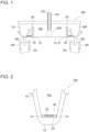
- Fig. 1 is a diagram illustrating a structure of a continuous casting tundish.
- Fig. 2 is a diagram illustrating a side view of the continuous casting tundish.
- a continuous casting tundish 100 is disposed between a ladle (not illustrated), in which molten steel MS is stored, and a casting mold 40, in which the molten steel MS is cooled.
- the continuous casting tundish 100 includes a reservoir 10, which has a box shape with an open upper portion and a closed bottom.
- the reservoir 10 of the continuous casting tundish 100 has an inverted frustum shape, with the upper base being longer than the lower base.
- the reservoir 10 has a space 10a, in which the molten steel MS can be stored.
- the reservoir 10 includes a molten steel pouring region AR1, to which the molten steel MS is poured from a nozzle N1 of the ladle.
- the molten steel pouring region AR1 is formed along an axis AX of the nozzle N1.
- the molten steel pouring region AR1 is formed to extend from an end of the nozzle N1 along the axis AX of the nozzle N1.
- the molten steel pouring region AR1 is a region expanding in a direction towards a periphery of the axis AX of the nozzle N1.
- the reservoir 10 includes one or more molten steel outlets 11, which allows the molten steel MS to exit therethrough to the casting mold.
- molten steel outlets 11 are formed at one end and another end of a bottom portion 12 of the reservoir 10 in a left-and-right direction, as illustrated in Fig. 1 .
- the reservoir 10 includes one or more weirs 20, which divides the space 10a enclosed by the reservoir 10.
- weirs 20 are provided such that the molten steel pouring region AR1 is divided from the molten steel outlets 11 by the weirs 20.
- the weirs 20 are two weirs provided such that the molten steel outlets 11, which are provided in the left-and-right direction of the reservoir 10, can be divided from the molten steel pouring region AR1.
- the weirs 20 have a plate shape, for example.
- the weirs 20 have a through-hole 21, which is disposed near the bottom portion 12 of the reservoir 10.
- the through-hole 21 extends from an area of on a molten steel pouring region AR1-side to an area of a molten steel outlet 11-side.
- the reservoir 10 includes a gas supply unit 30, which supplies an inert gas to the space 10a enclosed by the reservoir 10.
- the gas supply unit 30 is located at upstream side of the molten steel MS from the molten steel outlet 11.
- the gas supply unit 30 serves as a gas supply device that supplies an inert gas to the reservoir 10.
- the gas supply unit 30 is hollow and has a box shape with a closed bottom.
- the gas supply unit 30 includes a wall portion 31 and a bottom portion 32, which is provided at a lower end of the wall portion 31.
- the wall portion 31 rises from the bottom portion 32.
- the bottom portion 32 faces the bottom portion 12 of the reservoir 10 and is in contact with the bottom portion 23.
- the gas supply unit 30 may be provided in a region of the reservoir 10 in which a flow speed of the molten steel MS is high. Examples of such a region include a vicinity of the weir 20.
- the gas supply unit 30 is provided adjacent to the weir 20 with respect to a moving direction of the molten steel MS.
- the gas supply unit 30 may be provided upstream of the weir 20 or downstream of the weir 20 with respect to the moving direction of the molten steel MS.
- the gas supply unit 30 is provided downstream of the weir 20 with respect to the moving direction of the molten steel MS.
- the gas supply unit 30 supplies an inert gas toward an upper end of the space 10a of the reservoir 10.
- the gas supply unit 30 supplies an inert gas in a direction along the axis AX of the nozzle N1.
- a nozzle N2 is provided at each of the molten steel outlets 11.
- the nozzle N2 connects the tundish 100 to the casting mold 40.
- the molten steel MS is supplied to the casting mold 40 from the molten steel outlets 11 via the nozzles N2.
- the molten steel MS is cooled in the casting mold 40 to form a cast steel 50.
- Fig. 3 is a diagram illustrating a structure of the gas supply unit 30.
- Fig. 4 is a top view of the gas supply unit 30. As illustrated in Figs. 3 and 4 , the gas supply unit 30 has a hollow box shape with the wall portion 31 and the bottom portion 32.
- the gas supply unit 30 includes a porous portion 35 and a support portion 36, which supports the porous portion 35.
- the porous portion 35 has pores 35a in an entirety thereof.
- the gas supply unit 30 also includes a pipe 37, which allows an inert gas to be delivered therethrough.
- the pipe 37 is provided in the wall portion 31 between the porous portion 35 and the bottom portion 32.
- the porous portion 35 is formed of a refractory material that is a ceramic.
- the refractory material may be, for example, a material obtained by sintering refractory inorganic particles, which may include one, or a mixture of two or more, selected from alumina, silica, and the like. Particularly preferably, the refractory material is a material formed primarily of alumina.
- the porous portion 35 can be prepared by firing spherical particles formed primarily of alumina, which are used as aggregates, at 1600°C or greater.
- the porous portion 35 can be produced, for example, by slip-casting a dense castable refractory material.
- the pores 35a of the porous portion 35 can be formed to have an average pore size of, for example, 10 to 40 ⁇ m as measured by mercury intrusion porosimetry.
- the bubbles of the inert gas supplied from the porous portion 35 can be fine bubbles.
- the size of the bubbles is approximately 100 ⁇ m, whereas when the inert gas is supplied in the manner just described, the size of the bubbles can be approximately 1/10 to 1/20 that of the related art.
- the pores 25a of the porous portion 25 are 10 to 40 ⁇ m, a flow rate of the inert gas can be appropriately controlled.
- the porous portion 35 may have any shape and, in the present embodiment, has a plate shape. Specifically, the shape is a rectangular shape in a top view, as illustrated in Fig. 4 .
- the support portion 36 is formed of a refractory material that is a ceramic.
- the refractory material may be, for example, a material obtained by sintering refractory inorganic particles, which may include one, or a mixture of two or more, selected from alumina, silica, and the like. Particularly preferably, the refractory material is a material formed primarily of alumina.
- the support portion 36 is formed to have a frame shape that can support an edge of a bottom portion of the porous portion 35.
- the support portion 36 may have any shape and, in the present embodiment, has a rectangular frame shape in a top view.
- the support portion 36 is provided on the wall portion 31.
- the support portion 36 is secured, for example, by being fit into a mating recess (not illustrated) formed in the wall portion 31.
- the gas supply unit 30 includes a reception chamber 38, which is enclosed by the porous portion 35, the support portion 36, the wall portion 31, and the bottom portion 32.
- the wall portion 31 enclosing the reception chamber 38 has the pipe 37 provided therein.
- the pipe 37 may be refractory.
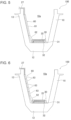
- Fig. 5 illustrates a state in which the pipe 27 is installed. As illustrated in Fig. 5 , the pipe 27 is disposed along a wall portion 13 of the reservoir 10. The pipe 27 is covered with a covering material 60, which is refractory. Examples of the covering material 60 include precast refractory materials. The covering material 60 may be a combination of a precast refractory material and a patching material. In the example illustrated in Fig. 5 , the covering material 60 located adjacent to the periphery of the reservoir 10 is made of a precast refractory material 61. Another covering material 60 located adjacent to the bottom portion 12 of the tundish 100 is made of a patching material 62.
- the covering material 60 may be a pipe cover.
- Fig. 6 illustrates another state in which the pipe 27 is installed.
- a pipe cover 63 is used instead of a precast refractory material, which has been described in the example illustrated in Fig. 5 .
- the pipe cover 63 may be a plurality of pipe covers. In the example illustrated in Fig. 6 , four pipe covers 63 are connected together in an axial direction of the pipe 27.
- the maintainability of the pipe 27 can be improved compared to an instance in which the pipe 27 is inserted through the bottom portion 12 of the tundish 100. Furthermore, processing of the bottom portion 12 of the tundish 100 for inserting the pipe 27 through the bottom portion 12 is unnecessary, and, therefore, leakage of the molten steel from the bottom portion 12 can be inhibited.
- the pipe 37 is provided with an adjustment means 39, which adjusts the flow rate of the inert gas.
- the adjustment means 39 may be a valve.
- the adjustment means 39 may be manually operated, or a controller (not illustrated) may be used to adjust the opening degree.
- the inert gas supplied from the pipe 37 is introduced to the reception chamber 38. Once the inert gas is introduced to the reception chamber 38, a pressure of the inert gas is uniformly applied to a surface of the porous portion 35 that faces the bottom portion 32. As a result, the inert gas passes from the reception chamber 38 through the pores 35a of the porous portion 35 to be supplied to the space 10a.
- the gas supply unit 30 supplies the inert gas and, consequently, can inhibit variations in the state of supply of the inert gas.
- the inert gas include, but are not limited to, Ar, N 2 , and CO 2 .
- the inert gas is supplied to the porous portion 35 from the reception chamber 38.
- the inert gas may be supplied to the porous portion 35 without being passed through the reception chamber 38.
- an attachment (not illustrated) that can cover the bottom-portion-32-side surface of the porous portion 35 may be attached to the pipe 37 and used for supplying the inert gas.
- the tundish 100 is provided with the weir 20.
- the tundish 100 may be provided without the weir 20. Even in such a case, effects similar to those of the present embodiment can be produced by providing the gas supply unit 30 in the manner described above.
- the gas supply unit 30 it is preferable that, for example, the gas supply unit 30 be provided in a region in which the flow speed of the molten steel MS is higher than in other regions.
- An example of the region in which the flow speed of the molten steel MS is high is the molten steel pouring region AR1.
- a method for continuously casting steel is as follows.
- the molten steel MS is supplied to the tundish 100 through the nozzle N1 connected to the ladle (not illustrated).
- the tundish 100 inclusions present in the molten steel MS is removed.
- the molten steel MS is allowed to exit through the molten steel outlets 11 of the tundish 100 to the casting mold 40.
- the molten steel MS is cooled to manufacture a cast steel.
- the step of removing inclusions present in the molten steel MS in the tundish 100 includes a step of injecting an inert gas at a flow rate that satisfies inequality (1), shown below.
- 0.2 ⁇ R ⁇ 10.0 R is the flow rate [NL/(s ⁇ m 2 )] of the inert gas per unit area of the porous portion.
- the gas is advantageously supplied from the gas supply unit 30 at 0.2 to 10.0 NL/(s ⁇ m 2 ) and more preferably at 2.0 to 10.0 NL/ (s ⁇ m 2 ).
- the gas flow rate (R) per unit area of the porous portion 35 can be adjusted by the adjustment means 39.
- the tundish 100 of the present invention is designed to allow an inert gas to be supplied through the porous portion 35 and, consequently, enables fine bubbles of the inert gas to be supplied to the space 10a of the reservoir 10.
- a volume fraction of the inert gas in the molten steel MS can be increased, and, accordingly, inclusions present in the molten steel poured into the tundish 100 from a ladle can be efficiently floated.
- the flow speed of the molten steel MS in the vicinity of the weir 20 is particularly higher than in other regions. Accordingly, by supplying the inert gas to the space 10a of the reservoir 10 from a location adjacent to the weir 20, it is possible to increase the frequency at which the bubbles of the inert gas come into contact with one another. As a result, the size of the bubbles of the inert gas can be further reduced. Consequently, the volume fraction of the inert gas in the molten steel MS can be further increased. Furthermore, as a result of the installation of the gas supply unit 30 in a high-flow-speed region of the tundish 100, as described above, the bubbles of the inert gas can be finer than the bubbles of the related art.
- Fine bubbles make it possible to enhance an inclusions-floating effect. As a result, the entrainment of inclusions into the molten steel can be inhibited.
- the location at which the gas supply unit 30 is installed can be easily changed. Accordingly, by changing the location at which the porous portion 35 is installed, in accordance with the flow conditions of the molten steel in the tundish 100, it is possible to further promote the floating of inclusions and further inhibit the entrainment of the inclusions into the molten steel.
- the tundish 100 of the present invention can increase the inclusions-floating effect. Furthermore, since the floating of inclusions can be accomplished with a lower flow rate of the inert gas, the entrainment of slag in the tundish 100 can be inhibited. As described, with the tundish 100 of the present invention, inclusions can be floated efficiently, and the entrainment of inclusions into the molten steel can be inhibited; consequently, high-cleanliness steels can be manufactured.
- the slab prepared by continuous casting was subjected to a measurement of the number of inclusions, which was performed by ultrasonic inspection. Regarding the inclusions, those that had a size of 10 ⁇ m or greater were counted. The number of counted inclusions per m 2 of the slab was calculated and designated as a density.
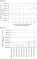
- Fig. 7 illustrates a relationship between the flow rate (R) of the inert gas per unit area of the porous portion and the density of inclusions in the slab. As illustrated in Fig. 7 , when the flow rate (R) of the inert gas was lower than 0.2, the density of inclusions was higher than those obtained under other conditions.
- the density of inclusions was lower than those obtained under other conditions.
- the density of inclusions was lower than those obtained under the conditions in which no inert gas was supplied. Furthermore, under those conditions, the density of inclusions was higher than those obtained under the conditions in which the flow rate (R) of the inert gas was less than or equal to 0.2.
- the inert gas caused tundish slag (inclusions) to be entrained into the molten steel. This is believed to be a reason that under this condition, the density of inclusions was higher than in the instances in which the flow rate (R) of the inert gas was 0.2 to 10.0.
- the inert gas that was injected into each of the tundishes was Ar. Specifically, in Conventional Example 1, the inert gas was supplied to the space of the reservoir, with no gas supply device provided in the tundish.
- the gas supply device was provided, and the inert gas was supplied to the space of the reservoir from the gas supply device.
- the Invention Examples (Present Inventions 1 to 9) were carried out with the flow rate of the inert gas supplied from the gas supply unit of the weir being varied. The flow rates of the inert gas are shown in Table 1. [Table 1] R Conventional Example 1 - Present Invention 1 2.0 Present Invention 2 4.0 Present Invention 3 6.0 Present Invention 4 8.0 Present Invention 5 0.2 Present Invention 6 10.0 Present Invention 7 12.0 Present Invention 8 14.0 Present Invention 9 0.1 R: the flow rate [NL/(s ⁇ m 2 )] of the inert gas per unit area of the porous portion
- Fig. 8 illustrates the density of inclusions of Conventional Example 1 and Invention Examples 1 to 9. As illustrated in Fig. 8 , it was found that in Present Inventions 1 to 9, the density of inclusions in the slab was much lower than in Conventional Example 1. In particular, in Present Inventions 1 to 6, since the flow rate (R) of the inert gas was 0.2 to 10.0, the obtained results were better than those of Present Inventions 7 to 9.
Landscapes
- Engineering & Computer Science (AREA)
- Mechanical Engineering (AREA)
- Continuous Casting (AREA)
- Treatment Of Steel In Its Molten State (AREA)
Abstract
Description
- The present invention relates to a continuous casting tundish, a method for continuously casting steel, and a gas supply device.
- A process for manufacturing steel materials is as follows. Molten steel is supplied from a ladle to a tundish. The molten steel is then supplied to a casting mold and cast to form a cast steel. The cast steel is subjected to processes including rolling and thus formed into a predetermined shape to serve as a steel material.
- Inclusions in molten steel, such as Al2O3, can cause a defect in the steel material, and, therefore, it is preferable to separate and remove inclusions from molten steel prior to casting. Specifically, an approach being used in tundishes is to separate inclusions present in molten steel by causing the inclusions to float.
- Such a cleaning technique for removing inclusions from molten steel is indispensable for the manufacture of high-quality steel materials, and, accordingly, a need exists to improve the technique. In the related art, an approach being used is to provide a tundish with a weir that separates a steel receiving region, to which molten steel is supplied, from a steel quasi-static region, from which the molten steel is discharged through an outlet provided in a bottom portion.
- A weir described in
Patent Literature 1, for example, has holes formed in a region adjacent to a bottom portion of a tundish, the holes extending from an area of a steel receiving region-side to an area of a steel quasi-static region-side. The weir limits the movement of inclusions that have a lower specific gravity than molten steel. The molten steel flows from the steel receiving region-side to the steel quasi-static region-side by passing through the holes of the weir. - Patent Literature 2 discloses that a weir described in
Patent Literature 1 is provided in a tundish and also discloses that a rib extending upward from a bottom portion of the tundish is provided on the steel quasi-static region-side. Accordingly, even when inclusions move to the steel quasi-static region-side through the holes of the weir, the direction of their movement can be changed to an upper direction by the rib. Accordingly, the inclusions can be floated even on the steel receiving region-side. -
Patent Literature 3 discloses that a weir described inPatent Literature 1 is provided in a tundish and also discloses that an inert gas is supplied to the steel quasi-static region-side from a bottom portion of the tundish toward an upper end. Accordingly, even when inclusions move to the steel quasi-static region-side through the holes of the weir, the inclusions are floated by the inert gas. -
- PTL 1:
Japanese Unexamined Patent Application Publication No. 53-6231 - PTL 2:
Japanese Unexamined Patent Application Publication No. 10-216909 - PTL 3:
Japanese Unexamined Patent Application Publication No. 2011-143449 - Even in the instance where a weir is provided in a tundish as disclosed in
Patent Literature 1, inclusions may pass through the holes of the weir. When inclusions are discharged from the molten steel outlet, there is a concern that defects may occur in a steel material. - Regarding the floating of inclusions by using a rib as disclosed in Patent Literature 2, a need exists to more effectively float inclusions, and, therefore, there is still room for improvement. Furthermore, a problem arises in that the molten steel between the rib and the weir remains when the casting is completed, which results in an increase in cost associated with the disposal of the remaining steel.
- In the instance where inclusions are floated by using an inert gas as disclosed in
Patent Literature 3, one problem is that a volume fraction of the inert gas in the molten steel needs to be increased so that a sufficient floating effect can be produced. When the flow rate of the inert gas is increased to increase the volume fraction of the inert gas in the molten steel, there is a concern that tundish slag, which is an inclusion present on a surface of molten steel, may be entrained into the molten steel by the inert gas. When tundish slag is entrained into molten steel, the molten steel is contaminated, and, consequently, there is a concern that defects may occur in a steel material. - The present invention has been made in view of the problems described above, and objects of the present invention are to provide a continuous casting tundish capable of increasing the cleanliness of molten steel, to provide a method for continuously casting steel, and to provide a gas supply device.
- The present invention is directed toward solving the problems described above and has the following features.
- [1] A continuous casting tundish including a reservoir that stores supplied molten steel, wherein
the reservoir includes one or more molten steel outlets that allows the molten steel to exit therethrough, and the reservoir also includes a gas supply unit that supplies an inert gas to a space enclosed by the reservoir, the gas supply unit being located at upstream side of the molten steel from one or more molten steel outlets, the gas supply unit having a box shape with a bottom portion and a wall portion and including:- a porous portion including pores in an entirety of the porous portion;
- a support portion that supports the porous portion, the support portion being provided on the wall portion of the gas supply unit; and
- a pipe that allows the inert gas to be delivered therethrough, the pipe being provided in the wall portion of the gas supply unit between the support portion and the bottom portion of the gas supply unit.
- [2] The continuous casting tundish according to [1], wherein
- the gas supply unit further includes a reception chamber enclosed by the porous portion, the support portion, the wall portion of the gas supply unit, and the bottom portion of the gas supply unit, and
- the pipe is provided in the wall portion of the gas supply unit, the wall portion enclosing the reception chamber.
- [3] The continuous casting tundish according to [1] or [2], wherein the reservoir includes one or more weirs that divides the space enclosed by the reservoir, and the gas supply unit is provided adjacent to the weir.
- [4] The continuous casting tundish according to any one of [1] to [3], wherein the gas supply unit further includes an adjustment means that adjusts a flow rate of the inert gas that is supplied from the pipe.
- [5] The continuous casting tundish according to any one of [1] to [4], wherein the pipe is disposed along a wall portion of the reservoir and covered with a covering material that is refractory.
- [6] A method for continuously casting steel including using the continuous casting tundish according to any one of [1] to [5], wherein the method includes a step of injecting an inert gas at a flow rate that satisfies inequality (1), shown below:

- [7] A gas supply device that is installed in a continuous casting tundish and supplies an inert gas, the gas supply device having a box shape with a bottom portion and a wall portion and including:
- a porous portion including pores in an entirety of the porous portion;
- a support portion that supports the porous portion, the support portion being provided on the wall portion; and
- a pipe that allows the inert gas to be delivered therethrough, the pipe being provided in the wall portion between the support portion and the bottom portion.
- [8] The gas supply device according to [7], further including a reception chamber enclosed by the porous portion, the support portion, the wall portion, and the bottom portion, wherein
the pipe is provided in the wall portion enclosing the reception chamber. - [9] The gas supply device according to [7] or [8], further including an adjustment means that adjusts a flow rate of the inert gas that is supplied from the pipe.
- The present invention is designed to allow an inert gas to be supplied through a porous portion and, consequently, enables fine bubbles of the inert gas to be supplied to a molten steel pouring region. As a result, a volume fraction of the inert gas in the molten steel can be increased, and, accordingly, inclusions present in the molten steel poured into a tundish from a ladle can be efficiently floated. Hence, the cleanliness of the molten steel can be increased.
-
- [
Fig. 1] Fig. 1 is a diagram illustrating a structure of a continuous casting tundish. - [
Fig. 2] Fig. 2 is a diagram illustrating a side view of the continuous casting tundish. - [
Fig. 3] Fig. 3 is a diagram illustrating a structure of a gas supply unit, illustrated inFig. 1 . - [
Fig. 4] Fig. 4 is a top view of the gas supply unit, illustrated inFig. 3 . - [
Fig. 5] Fig. 5 is a diagram illustrating a state in which a pipe is installed. - [
Fig. 6] Fig. 6 is a diagram illustrating another state in which a pipe is installed. - [
Fig. 7] Fig. 7 is a graph illustrating a relationship between a gas flow rate per unit area and a number density of inclusions. - [
Fig. 8] Fig. 8 is a graph illustrating the number density of inclusions of a Conventional Example and Present Inventions. -
Fig. 1 is a diagram illustrating a structure of a continuous casting tundish.Fig. 2 is a diagram illustrating a side view of the continuous casting tundish. As illustrated inFig. 1 , acontinuous casting tundish 100 is disposed between a ladle (not illustrated), in which molten steel MS is stored, and a castingmold 40, in which the molten steel MS is cooled. - As illustrated in
Figs. 1 and 2 , the continuous casting tundish (hereinafter simply referred to as a "tundish") 100 includes areservoir 10, which has a box shape with an open upper portion and a closed bottom. In the present embodiment, thereservoir 10 of thecontinuous casting tundish 100 has an inverted frustum shape, with the upper base being longer than the lower base. Thereservoir 10 has aspace 10a, in which the molten steel MS can be stored. - The
reservoir 10 includes a molten steel pouring region AR1, to which the molten steel MS is poured from a nozzle N1 of the ladle. The molten steel pouring region AR1 is formed along an axis AX of the nozzle N1. In other words, the molten steel pouring region AR1 is formed to extend from an end of the nozzle N1 along the axis AX of the nozzle N1. The molten steel pouring region AR1 is a region expanding in a direction towards a periphery of the axis AX of the nozzle N1. - The
reservoir 10 includes one or moremolten steel outlets 11, which allows the molten steel MS to exit therethrough to the casting mold. In the present embodiment,molten steel outlets 11 are formed at one end and another end of abottom portion 12 of thereservoir 10 in a left-and-right direction, as illustrated inFig. 1 . - The
reservoir 10 includes one ormore weirs 20, which divides thespace 10a enclosed by thereservoir 10. In the present embodiment,weirs 20 are provided such that the molten steel pouring region AR1 is divided from themolten steel outlets 11 by theweirs 20. Theweirs 20 are two weirs provided such that themolten steel outlets 11, which are provided in the left-and-right direction of thereservoir 10, can be divided from the molten steel pouring region AR1. - The
weirs 20 have a plate shape, for example. Theweirs 20 have a through-hole 21, which is disposed near thebottom portion 12 of thereservoir 10. The through-hole 21 extends from an area of on a molten steel pouring region AR1-side to an area of a molten steel outlet 11-side. - The
reservoir 10 includes agas supply unit 30, which supplies an inert gas to thespace 10a enclosed by thereservoir 10. Thegas supply unit 30 is located at upstream side of the molten steel MS from themolten steel outlet 11. In other words, thegas supply unit 30 serves as a gas supply device that supplies an inert gas to thereservoir 10. Thegas supply unit 30 is hollow and has a box shape with a closed bottom. - As illustrated in
Fig. 2 , thegas supply unit 30 includes awall portion 31 and abottom portion 32, which is provided at a lower end of thewall portion 31. In other words, thewall portion 31 rises from thebottom portion 32. Thebottom portion 32 faces thebottom portion 12 of thereservoir 10 and is in contact with the bottom portion 23. - Advantageously, the
gas supply unit 30 may be provided in a region of thereservoir 10 in which a flow speed of the molten steel MS is high. Examples of such a region include a vicinity of theweir 20. In the present embodiment, thegas supply unit 30 is provided adjacent to theweir 20 with respect to a moving direction of the molten steel MS. Thegas supply unit 30 may be provided upstream of theweir 20 or downstream of theweir 20 with respect to the moving direction of the molten steel MS. In the present embodiment, thegas supply unit 30 is provided downstream of theweir 20 with respect to the moving direction of the molten steel MS. - The
gas supply unit 30 supplies an inert gas toward an upper end of thespace 10a of thereservoir 10. In the present embodiment, thegas supply unit 30 supplies an inert gas in a direction along the axis AX of the nozzle N1. - A nozzle N2 is provided at each of the
molten steel outlets 11. The nozzle N2 connects thetundish 100 to the castingmold 40. The molten steel MS is supplied to the castingmold 40 from themolten steel outlets 11 via the nozzles N2. The molten steel MS is cooled in the castingmold 40 to form acast steel 50. -
Fig. 3 is a diagram illustrating a structure of thegas supply unit 30.Fig. 4 is a top view of thegas supply unit 30. As illustrated inFigs. 3 and 4 , thegas supply unit 30 has a hollow box shape with thewall portion 31 and thebottom portion 32. - The
gas supply unit 30 includes aporous portion 35 and asupport portion 36, which supports theporous portion 35. Theporous portion 35 haspores 35a in an entirety thereof. Thegas supply unit 30 also includes apipe 37, which allows an inert gas to be delivered therethrough. Thepipe 37 is provided in thewall portion 31 between theporous portion 35 and thebottom portion 32. - The
porous portion 35 is formed of a refractory material that is a ceramic. The refractory material may be, for example, a material obtained by sintering refractory inorganic particles, which may include one, or a mixture of two or more, selected from alumina, silica, and the like. Particularly preferably, the refractory material is a material formed primarily of alumina. - The
porous portion 35 can be prepared by firing spherical particles formed primarily of alumina, which are used as aggregates, at 1600°C or greater. Theporous portion 35 can be produced, for example, by slip-casting a dense castable refractory material. - The use of spherical particles as aggregates enables the formation of the
pores 35a of theporous portion 35. Without limitation, thepores 35a of theporous portion 35 can be formed to have an average pore size of, for example, 10 to 40 µm as measured by mercury intrusion porosimetry. In the instance where thepores 35a are formed as such, the bubbles of the inert gas supplied from theporous portion 35 can be fine bubbles. Specifically, when the inert gas is supplied in a manner of the related art, the size of the bubbles is approximately 100 µm, whereas when the inert gas is supplied in the manner just described, the size of the bubbles can be approximately 1/10 to 1/20 that of the related art. Furthermore, when the pores 25a of the porous portion 25 are 10 to 40 µm, a flow rate of the inert gas can be appropriately controlled. - The
porous portion 35 may have any shape and, in the present embodiment, has a plate shape. Specifically, the shape is a rectangular shape in a top view, as illustrated inFig. 4 . - The
support portion 36 is formed of a refractory material that is a ceramic. The refractory material may be, for example, a material obtained by sintering refractory inorganic particles, which may include one, or a mixture of two or more, selected from alumina, silica, and the like. Particularly preferably, the refractory material is a material formed primarily of alumina. - The
support portion 36 is formed to have a frame shape that can support an edge of a bottom portion of theporous portion 35. Thesupport portion 36 may have any shape and, in the present embodiment, has a rectangular frame shape in a top view. Thesupport portion 36 is provided on thewall portion 31. Thesupport portion 36 is secured, for example, by being fit into a mating recess (not illustrated) formed in thewall portion 31. - The
gas supply unit 30 includes areception chamber 38, which is enclosed by theporous portion 35, thesupport portion 36, thewall portion 31, and thebottom portion 32. Thewall portion 31 enclosing thereception chamber 38 has thepipe 37 provided therein. - Advantageously, the
pipe 37 may be refractory.Fig. 5 illustrates a state in which thepipe 27 is installed. As illustrated inFig. 5 , thepipe 27 is disposed along awall portion 13 of thereservoir 10. Thepipe 27 is covered with a coveringmaterial 60, which is refractory. Examples of the coveringmaterial 60 include precast refractory materials. The coveringmaterial 60 may be a combination of a precast refractory material and a patching material. In the example illustrated inFig. 5 , the coveringmaterial 60 located adjacent to the periphery of thereservoir 10 is made of a precastrefractory material 61. Another coveringmaterial 60 located adjacent to thebottom portion 12 of thetundish 100 is made of a patchingmaterial 62. - Furthermore, the covering
material 60 may be a pipe cover.Fig. 6 illustrates another state in which thepipe 27 is installed. In the example illustrated inFig. 6 , apipe cover 63 is used instead of a precast refractory material, which has been described in the example illustrated inFig. 5 . In addition, thepipe cover 63 may be a plurality of pipe covers. In the example illustrated inFig. 6 , four pipe covers 63 are connected together in an axial direction of thepipe 27. - With this configuration of the
pipe 27, the installation of a refractory material can be facilitated. - In addition, the maintainability of the
pipe 27 can be improved compared to an instance in which thepipe 27 is inserted through thebottom portion 12 of thetundish 100. Furthermore, processing of thebottom portion 12 of thetundish 100 for inserting thepipe 27 through thebottom portion 12 is unnecessary, and, therefore, leakage of the molten steel from thebottom portion 12 can be inhibited. - Preferably, the
pipe 37 is provided with an adjustment means 39, which adjusts the flow rate of the inert gas. The adjustment means 39 may be a valve. The adjustment means 39 may be manually operated, or a controller (not illustrated) may be used to adjust the opening degree. - The inert gas supplied from the
pipe 37 is introduced to thereception chamber 38. Once the inert gas is introduced to thereception chamber 38, a pressure of the inert gas is uniformly applied to a surface of theporous portion 35 that faces thebottom portion 32. As a result, the inert gas passes from thereception chamber 38 through thepores 35a of theporous portion 35 to be supplied to thespace 10a. - In this manner, the
gas supply unit 30 supplies the inert gas and, consequently, can inhibit variations in the state of supply of the inert gas. Examples of the inert gas include, but are not limited to, Ar, N2, and CO2. - In the present embodiment, the inert gas is supplied to the
porous portion 35 from thereception chamber 38. Alternatively, the inert gas may be supplied to theporous portion 35 without being passed through thereception chamber 38. For example, an attachment (not illustrated) that can cover the bottom-portion-32-side surface of theporous portion 35 may be attached to thepipe 37 and used for supplying the inert gas. - In the example described in the present embodiment, the
tundish 100 is provided with theweir 20. Alternatively, thetundish 100 may be provided without theweir 20. Even in such a case, effects similar to those of the present embodiment can be produced by providing thegas supply unit 30 in the manner described above. In the instance where thetundish 100 is provided without theweir 20, it is preferable that, for example, thegas supply unit 30 be provided in a region in which the flow speed of the molten steel MS is higher than in other regions. An example of the region in which the flow speed of the molten steel MS is high is the molten steel pouring region AR1. - A method for continuously casting steel is as follows. In a first step, the molten steel MS is supplied to the
tundish 100 through the nozzle N1 connected to the ladle (not illustrated). In the next step, in thetundish 100, inclusions present in the molten steel MS is removed. In the next step, the molten steel MS is allowed to exit through themolten steel outlets 11 of thetundish 100 to the castingmold 40. In the next step, in the castingmold 40, the molten steel MS is cooled to manufacture a cast steel. - The step of removing inclusions present in the molten steel MS in the
tundish 100 includes a step of injecting an inert gas at a flow rate that satisfies inequality (1), shown below.
- Regarding the gas flow rate (R) per unit area of the
porous portion 35, the gas is advantageously supplied from thegas supply unit 30 at 0.2 to 10.0 NL/(s×m2) and more preferably at 2.0 to 10.0 NL/ (s×m2). The gas flow rate (R) per unit area of theporous portion 35 can be adjusted by the adjustment means 39. - When the gas flow rate (R) per unit area of the
porous portion 35 is 0.2 NL/(s×m2) or greater, the floating of inclusions in the molten steel MS can be promoted. - When the gas flow rate (R) per unit area of the
porous portion 35 is 10.0 NL/(s×m2) or less, the entrainment of tundish slag can be prevented. - As described, the
tundish 100 of the present invention is designed to allow an inert gas to be supplied through theporous portion 35 and, consequently, enables fine bubbles of the inert gas to be supplied to thespace 10a of thereservoir 10. As a result, a volume fraction of the inert gas in the molten steel MS can be increased, and, accordingly, inclusions present in the molten steel poured into thetundish 100 from a ladle can be efficiently floated. - The flow speed of the molten steel MS in the vicinity of the
weir 20 is particularly higher than in other regions. Accordingly, by supplying the inert gas to thespace 10a of thereservoir 10 from a location adjacent to theweir 20, it is possible to increase the frequency at which the bubbles of the inert gas come into contact with one another. As a result, the size of the bubbles of the inert gas can be further reduced. Consequently, the volume fraction of the inert gas in the molten steel MS can be further increased. Furthermore, as a result of the installation of thegas supply unit 30 in a high-flow-speed region of thetundish 100, as described above, the bubbles of the inert gas can be finer than the bubbles of the related art. Fine bubbles make it possible to enhance an inclusions-floating effect. As a result, the entrainment of inclusions into the molten steel can be inhibited. Note that the location at which thegas supply unit 30 is installed can be easily changed. Accordingly, by changing the location at which theporous portion 35 is installed, in accordance with the flow conditions of the molten steel in thetundish 100, it is possible to further promote the floating of inclusions and further inhibit the entrainment of the inclusions into the molten steel. - Accordingly, the
tundish 100 of the present invention can increase the inclusions-floating effect. Furthermore, since the floating of inclusions can be accomplished with a lower flow rate of the inert gas, the entrainment of slag in thetundish 100 can be inhibited. As described, with thetundish 100 of the present invention, inclusions can be floated efficiently, and the entrainment of inclusions into the molten steel can be inhibited; consequently, high-cleanliness steels can be manufactured. - 300 tons of molten steel, which had undergone oxygen blowing in a converter and an RH vacuum degassing process, was used. The molten steel was supplied to a tundish from a ladle.
- Continuous casting was performed by using Ar as an inert gas that was injected from a weir. Specifically, several tests were performed with the flow rate (R) of the inert gas per unit area of the porous portion being varied (R is the flow rate [NL/(s×m2)] of the inert gas per unit area of the porous portion).
- The slab prepared by continuous casting was subjected to a measurement of the number of inclusions, which was performed by ultrasonic inspection. Regarding the inclusions, those that had a size of 10 µm or greater were counted. The number of counted inclusions per m2 of the slab was calculated and designated as a density.
-
Fig. 7 illustrates a relationship between the flow rate (R) of the inert gas per unit area of the porous portion and the density of inclusions in the slab. As illustrated inFig. 7 , when the flow rate (R) of the inert gas was lower than 0.2, the density of inclusions was higher than those obtained under other conditions. - When the flow rate (R) of the inert gas was 0.2 to 10.0, the density of inclusions was lower than those obtained under other conditions. When the flow rate (R) of the inert gas was greater than 10.0, the density of inclusions was lower than those obtained under the conditions in which no inert gas was supplied. Furthermore, under those conditions, the density of inclusions was higher than those obtained under the conditions in which the flow rate (R) of the inert gas was less than or equal to 0.2.
- Regarding the instance where the flow rate (R) of the inert gas was lower than 0.2, it is believed that under this condition, the effect of floating inclusions in a tundish could not be sufficiently produced. This is believed to be a reason that the density of inclusions was high under this condition.
- Furthermore, it is believed that under the conditions in which the flow rate (R) of the inert gas was greater than 10.0, the inert gas caused tundish slag (inclusions) to be entrained into the molten steel. This is believed to be a reason that under this condition, the density of inclusions was higher than in the instances in which the flow rate (R) of the inert gas was 0.2 to 10.0.
- The same molten steel as that of Test Example 1 was used.
- Continuous casting was performed using tundishes of Conventional Example (1) and Invention Examples (
Present Inventions 1 to 9). - The inert gas that was injected into each of the tundishes was Ar. Specifically, in Conventional Example 1, the inert gas was supplied to the space of the reservoir, with no gas supply device provided in the tundish.
- In the Invention Examples, the gas supply device was provided, and the inert gas was supplied to the space of the reservoir from the gas supply device. The Invention Examples (
Present Inventions 1 to 9) were carried out with the flow rate of the inert gas supplied from the gas supply unit of the weir being varied. The flow rates of the inert gas are shown in Table 1.[Table 1] R Conventional Example 1 - Present Invention 12.0 Present Invention 2 4.0 Present Invention 36.0 Present Invention 4 8.0 Present Invention 5 0.2 Present Invention 6 10.0 Present Invention 7 12.0 Present Invention 8 14.0 Present Invention 9 0.1 R: the flow rate [NL/(s×m2)] of the inert gas per unit area of the porous portion - The measurement was performed in the same manner as in Test Example 1.
-
Fig. 8 illustrates the density of inclusions of Conventional Example 1 and Invention Examples 1 to 9. As illustrated inFig. 8 , it was found that inPresent Inventions 1 to 9, the density of inclusions in the slab was much lower than in Conventional Example 1. In particular, inPresent Inventions 1 to 6, since the flow rate (R) of the inert gas was 0.2 to 10.0, the obtained results were better than those of Present Inventions 7 to 9. -
- 100
- tundish
- 10
- reservoir
- 10a
- space
- 11
- molten steel outlet
- 20
- weir
- 30
- gas supply unit (gas supply device)
- 31
- wall portion
- 32
- bottom portion
- 35
- porous portion
- 36
- support portion
- 37
- pipe
- 38
- reception chamber
- 39
- adjustment means
- AR1
- molten steel pouring region
Claims (20)
- A continuous casting tundish comprising a reservoir that stores supplied molten steel, wherein
the reservoir comprises one or more molten steel outlets that allows the molten steel to exit therethrough, and the reservoir also comprises a gas supply unit that supplies an inert gas to a space enclosed by the reservoir, the gas supply unit being located at upstream side of the molten steel from one or more molten steel outlets, the gas supply unit having a box shape with a bottom portion and a wall portion and comprising:a porous portion comprising pores in an entirety of the porous portion;a support portion that supports the porous portion, the support portion being provided on the wall portion of the gas supply unit; anda pipe that allows the inert gas to be delivered therethrough, the pipe being provided in the wall portion of the gas supply unit between the support portion and the bottom portion of the gas supply unit. - The continuous casting tundish according to Claim 1, whereinthe gas supply unit further comprises a reception chamber enclosed by the porous portion, the support portion, the wall portion of the gas supply unit, and the bottom portion of the gas supply unit, andthe pipe is provided in the wall portion of the gas supply unit, the wall portion enclosing the reception chamber.
- The continuous casting tundish according to Claim 1 or 2, wherein the reservoir comprises one or more weirs that divide the space enclosed by the reservoir, and the gas supply unit is provided adjacent to the weir.
- The continuous casting tundish according to Claim 1 or 2, wherein the gas supply unit further comprises an adjustment means that adjusts a flow rate of the inert gas that is supplied from the pipe.
- The continuous casting tundish according to Claim 3, wherein the gas supply unit further comprises an adjustment means that adjusts a flow rate of the inert gas that is supplied from the pipe.
- The continuous casting tundish according to Claim 1 or 2, wherein the pipe is disposed along a wall portion of the reservoir and covered with a covering material that is refractory.
- The continuous casting tundish according to Claim 3, wherein the pipe is disposed along a wall portion of the reservoir and covered with a covering material that is refractory.
- The continuous casting tundish according to Claim 4, wherein the pipe is disposed along a wall portion of the reservoir and covered with a covering material that is refractory.
- The continuous casting tundish according to Claim 5, wherein the pipe is disposed along a wall portion of the reservoir and covered with a covering material that is refractory.
- A method for continuously casting steel comprising using the continuous casting tundish according to Claim 1 or 2, wherein the method comprises a step of injecting the inert gas at a flow rate that satisfies inequality (1), shown below:

- A method for continuously casting steel comprising using the continuous casting tundish according to Claim 3, wherein the method comprises a step of injecting the inert gas at a flow rate that satisfies inequality (1), shown below:

- A method for continuously casting steel comprising using the continuous casting tundish according to Claim 4, wherein the method comprises a step of injecting the inert gas at a flow rate that satisfies inequality (1), shown below:

- A method for continuously casting steel comprising using the continuous casting tundish according to Claim 5, wherein the method comprises a step of injecting the inert gas at a flow rate that satisfies inequality (1), shown below:

- A method for continuously casting steel comprising using the continuous casting tundish according to Claim 6, wherein the method comprises a step of injecting the inert gas at a flow rate that satisfies inequality (1), shown below:

- A method for continuously casting steel comprising using the continuous casting tundish according to Claim 7, wherein the method comprises a step of injecting the inert gas at a flow rate that satisfies inequality (1), shown below:

- A method for continuously casting steel comprising using the continuous casting tundish according to Claim 8, wherein the method comprises a step of injecting the inert gas at a flow rate that satisfies inequality (1), shown below:

- A method for continuously casting steel comprising using the continuous casting tundish according to Claim 9, wherein the method comprises a step of injecting the inert gas at a flow rate that satisfies inequality (1), shown below:

- A gas supply device that is installed in a continuous casting tundish and supplies an inert gas, the gas supply device having a box shape with a bottom portion and a wall portion and comprising:a porous portion comprising pores in an entirety of the porous portion;a support portion that supports the porous portion, the support portion being provided on the wall portion; anda pipe that allows the inert gas to be delivered therethrough, the pipe being provided in the wall portion between the support portion and the bottom portion.
- The gas supply device according to Claim 18, further comprising a reception chamber enclosed by the porous portion, the support portion, the wall portion, and the bottom portion, wherein
the pipe is provided in the wall portion enclosing the reception chamber. - The gas supply device according to Claim 18 or 19, further comprising an adjustment means that adjusts a flow rate of the inert gas that is supplied from the pipe.
Applications Claiming Priority (2)
| Application Number | Priority Date | Filing Date | Title |
|---|---|---|---|
| JP2022143847 | 2022-09-09 | ||
| PCT/JP2023/028183 WO2024053291A1 (en) | 2022-09-09 | 2023-08-01 | Tundish for continuous casting, steel continuous casting method, and gas supply device |
Publications (2)
| Publication Number | Publication Date |
|---|---|
| EP4549051A1 true EP4549051A1 (en) | 2025-05-07 |
| EP4549051A4 EP4549051A4 (en) | 2025-10-22 |
Family
ID=90190914
Family Applications (1)
| Application Number | Title | Priority Date | Filing Date |
|---|---|---|---|
| EP23862834.1A Pending EP4549051A4 (en) | 2022-09-09 | 2023-08-01 | INTERMEDIATE TANK FOR CONTINUOUS CASTING, CONTINUOUS STEEL CASTING PROCESS AND GAS SUPPLY DEVICE |
Country Status (5)
| Country | Link |
|---|---|
| EP (1) | EP4549051A4 (en) |
| JP (1) | JP7677461B2 (en) |
| KR (1) | KR20250044728A (en) |
| CN (1) | CN119789923A (en) |
| WO (1) | WO2024053291A1 (en) |
Family Cites Families (10)
| Publication number | Priority date | Publication date | Assignee | Title |
|---|---|---|---|---|
| JPS536231A (en) | 1976-07-07 | 1978-01-20 | Nippon Kokan Kk | Method of making clean steel |
| JP3563222B2 (en) | 1997-01-31 | 2004-09-08 | 日本冶金工業株式会社 | Tundish for continuous casting of steel |
| CN2863315Y (en) * | 2005-12-01 | 2007-01-31 | 洛阳铁门耐火材料有限公司 | Blowing type turbulence proof controller for bakie |
| JP5134574B2 (en) | 2009-03-16 | 2013-01-30 | 曙ブレーキ工業株式会社 | Rotation axis stop position setting method in drag test device |
| JP2011143449A (en) | 2010-01-14 | 2011-07-28 | Jfe Steel Corp | Method for removing inclusion in tundish for continuous casting |
| CN104364032B (en) * | 2012-06-18 | 2017-02-22 | 杰富意钢铁株式会社 | Method for manufacturing high-purity steel casting, and tundish |
| JP5777603B2 (en) * | 2012-12-26 | 2015-09-09 | 株式会社神戸製鋼所 | Continuous casting method |
| CN203109191U (en) * | 2013-03-15 | 2013-08-07 | 濮阳濮耐高温材料(集团)股份有限公司 | Tundish current stabilizer with air blowing function |
| US11338357B2 (en) * | 2019-08-19 | 2022-05-24 | Harbisonwalker International, Inc. | Diffusion article |
| CN113564309B (en) * | 2020-04-28 | 2022-10-21 | 宝山钢铁股份有限公司 | Tundish with function of removing molten steel inclusions by blowing argon |
-
2023
- 2023-08-01 EP EP23862834.1A patent/EP4549051A4/en active Pending
- 2023-08-01 WO PCT/JP2023/028183 patent/WO2024053291A1/en not_active Ceased
- 2023-08-01 JP JP2023572687A patent/JP7677461B2/en active Active
- 2023-08-01 CN CN202380062611.6A patent/CN119789923A/en active Pending
- 2023-08-01 KR KR1020257006509A patent/KR20250044728A/en active Pending
Also Published As
| Publication number | Publication date |
|---|---|
| CN119789923A (en) | 2025-04-08 |
| JPWO2024053291A1 (en) | 2024-03-14 |
| EP4549051A4 (en) | 2025-10-22 |
| KR20250044728A (en) | 2025-04-01 |
| JP7677461B2 (en) | 2025-05-15 |
| WO2024053291A1 (en) | 2024-03-14 |
Similar Documents
| Publication | Publication Date | Title |
|---|---|---|
| JP5807719B2 (en) | High cleanliness steel slab manufacturing method and tundish | |
| EP3470149A1 (en) | Melt treating apparatus and melt treating method | |
| KR20000071098A (en) | Feeder of molten metal for moulds of continuous casting machines | |
| EP4545205A1 (en) | Tundish for continuous casting, continuous casting method for steel, and weir | |
| EP0576212B1 (en) | Purifying molten metal | |
| JP7157387B2 (en) | Nozzle on tundish | |
| JP5082700B2 (en) | Steel continuous casting method | |
| JP7677461B2 (en) | Tundish for continuous casting, method for continuous casting of steel, and gas supply device | |
| JP4815821B2 (en) | Continuous casting method of aluminum killed steel | |
| EP3825034A1 (en) | Slide plate and fixed plate of molten metal discharging apparatus and methods of recycling associated | |
| JP4240916B2 (en) | Tundish upper nozzle and continuous casting method | |
| EP4480601A1 (en) | Tundish and continuous casting method using same | |
| KR101914084B1 (en) | Molten material processing apparatus | |
| KR101794599B1 (en) | Apparatus for blowing gas and apparatus for processing molten material using the same | |
| JPH08117939A (en) | Method of blowing bubbles into molten steel | |
| JP5888165B2 (en) | Steel continuous casting method and equipment | |
| KR102209610B1 (en) | Nozzle apparatus | |
| KR102361362B1 (en) | Well block, apparatus for casting and method thereof | |
| JP4474948B2 (en) | Steel continuous casting method | |
| JP2000202602A (en) | Inclusion removal method in tundish for continuous casting | |
| JP3962249B2 (en) | Method for removing non-metallic inclusions in molten metal | |
| KR19990025093U (en) | Slag mixing reduction structure in molten steel in steelmaking process | |
| JP2024085132A (en) | Continuous casting method and pouring nozzle for ladle | |
| KR101881971B1 (en) | Casting apparatus and casging method using the same | |
| JP2023046614A (en) | Tundish device and operation method using the same |
Legal Events
| Date | Code | Title | Description |
|---|---|---|---|
| STAA | Information on the status of an ep patent application or granted ep patent |
Free format text: STATUS: THE INTERNATIONAL PUBLICATION HAS BEEN MADE |
|
| PUAI | Public reference made under article 153(3) epc to a published international application that has entered the european phase |
Free format text: ORIGINAL CODE: 0009012 |
|
| STAA | Information on the status of an ep patent application or granted ep patent |
Free format text: STATUS: REQUEST FOR EXAMINATION WAS MADE |
|
| 17P | Request for examination filed |
Effective date: 20250128 |
|
| AK | Designated contracting states |
Kind code of ref document: A1 Designated state(s): AL AT BE BG CH CY CZ DE DK EE ES FI FR GB GR HR HU IE IS IT LI LT LU LV MC ME MK MT NL NO PL PT RO RS SE SI SK SM TR |
|
| A4 | Supplementary search report drawn up and despatched |
Effective date: 20250919 |
|
| RIC1 | Information provided on ipc code assigned before grant |
Ipc: B22D 11/10 20060101AFI20250915BHEP Ipc: B22D 11/11 20060101ALI20250915BHEP Ipc: B22D 1/00 20060101ALI20250915BHEP Ipc: B22D 41/00 20060101ALI20250915BHEP Ipc: B22D 11/117 20060101ALI20250915BHEP |
|
| DAV | Request for validation of the european patent (deleted) | ||
| DAX | Request for extension of the european patent (deleted) |